EP1936617A2 - Objective lens driving device and optical disc apparatus - Google Patents
Objective lens driving device and optical disc apparatus Download PDFInfo
- Publication number
- EP1936617A2 EP1936617A2 EP07024433A EP07024433A EP1936617A2 EP 1936617 A2 EP1936617 A2 EP 1936617A2 EP 07024433 A EP07024433 A EP 07024433A EP 07024433 A EP07024433 A EP 07024433A EP 1936617 A2 EP1936617 A2 EP 1936617A2
- Authority
- EP
- European Patent Office
- Prior art keywords
- objective lens
- coils
- magnets
- region
- driving device
- Prior art date
- Legal status (The legal status is an assumption and is not a legal conclusion. Google has not performed a legal analysis and makes no representation as to the accuracy of the status listed.)
- Granted
Links
- 230000003287 optical effect Effects 0.000 title claims description 66
- 230000009471 action Effects 0.000 claims abstract description 11
- 230000005405 multipole Effects 0.000 claims abstract description 7
- 238000010586 diagram Methods 0.000 description 19
- 238000004519 manufacturing process Methods 0.000 description 7
- 239000000463 material Substances 0.000 description 5
- 230000004907 flux Effects 0.000 description 4
- 230000004044 response Effects 0.000 description 3
- 238000005476 soldering Methods 0.000 description 3
- 239000000853 adhesive Substances 0.000 description 2
- 230000001070 adhesive effect Effects 0.000 description 2
- 238000005516 engineering process Methods 0.000 description 2
- 230000006870 function Effects 0.000 description 2
- 238000000034 method Methods 0.000 description 2
- 230000008569 process Effects 0.000 description 2
- 239000011347 resin Substances 0.000 description 2
- 229920005989 resin Polymers 0.000 description 2
- 238000005452 bending Methods 0.000 description 1
- 230000005307 ferromagnetism Effects 0.000 description 1
- 230000001678 irradiating effect Effects 0.000 description 1
- 239000002184 metal Substances 0.000 description 1
- 238000012986 modification Methods 0.000 description 1
- 230000004048 modification Effects 0.000 description 1
- 238000012544 monitoring process Methods 0.000 description 1
- 229920000515 polycarbonate Polymers 0.000 description 1
- 239000004417 polycarbonate Substances 0.000 description 1
- 229920001296 polysiloxane Polymers 0.000 description 1
Images



Classifications
-
- G—PHYSICS
- G11—INFORMATION STORAGE
- G11B—INFORMATION STORAGE BASED ON RELATIVE MOVEMENT BETWEEN RECORD CARRIER AND TRANSDUCER
- G11B7/00—Recording or reproducing by optical means, e.g. recording using a thermal beam of optical radiation by modifying optical properties or the physical structure, reproducing using an optical beam at lower power by sensing optical properties; Record carriers therefor
- G11B7/08—Disposition or mounting of heads or light sources relatively to record carriers
- G11B7/09—Disposition or mounting of heads or light sources relatively to record carriers with provision for moving the light beam or focus plane for the purpose of maintaining alignment of the light beam relative to the record carrier during transducing operation, e.g. to compensate for surface irregularities of the latter or for track following
- G11B7/0925—Electromechanical actuators for lens positioning
- G11B7/0933—Details of stationary parts
-
- G—PHYSICS
- G11—INFORMATION STORAGE
- G11B—INFORMATION STORAGE BASED ON RELATIVE MOVEMENT BETWEEN RECORD CARRIER AND TRANSDUCER
- G11B7/00—Recording or reproducing by optical means, e.g. recording using a thermal beam of optical radiation by modifying optical properties or the physical structure, reproducing using an optical beam at lower power by sensing optical properties; Record carriers therefor
- G11B7/08—Disposition or mounting of heads or light sources relatively to record carriers
- G11B7/09—Disposition or mounting of heads or light sources relatively to record carriers with provision for moving the light beam or focus plane for the purpose of maintaining alignment of the light beam relative to the record carrier during transducing operation, e.g. to compensate for surface irregularities of the latter or for track following
- G11B7/0925—Electromechanical actuators for lens positioning
- G11B7/0935—Details of the moving parts
-
- G—PHYSICS
- G11—INFORMATION STORAGE
- G11B—INFORMATION STORAGE BASED ON RELATIVE MOVEMENT BETWEEN RECORD CARRIER AND TRANSDUCER
- G11B7/00—Recording or reproducing by optical means, e.g. recording using a thermal beam of optical radiation by modifying optical properties or the physical structure, reproducing using an optical beam at lower power by sensing optical properties; Record carriers therefor
- G11B7/12—Heads, e.g. forming of the optical beam spot or modulation of the optical beam
- G11B7/125—Optical beam sources therefor, e.g. laser control circuitry specially adapted for optical storage devices; Modulators, e.g. means for controlling the size or intensity of optical spots or optical traces
- G11B7/127—Lasers; Multiple laser arrays
- G11B7/1275—Two or more lasers having different wavelengths
-
- G—PHYSICS
- G11—INFORMATION STORAGE
- G11B—INFORMATION STORAGE BASED ON RELATIVE MOVEMENT BETWEEN RECORD CARRIER AND TRANSDUCER
- G11B7/00—Recording or reproducing by optical means, e.g. recording using a thermal beam of optical radiation by modifying optical properties or the physical structure, reproducing using an optical beam at lower power by sensing optical properties; Record carriers therefor
- G11B2007/0003—Recording, reproducing or erasing systems characterised by the structure or type of the carrier
- G11B2007/0006—Recording, reproducing or erasing systems characterised by the structure or type of the carrier adapted for scanning different types of carrier, e.g. CD & DVD
-
- G—PHYSICS
- G11—INFORMATION STORAGE
- G11B—INFORMATION STORAGE BASED ON RELATIVE MOVEMENT BETWEEN RECORD CARRIER AND TRANSDUCER
- G11B7/00—Recording or reproducing by optical means, e.g. recording using a thermal beam of optical radiation by modifying optical properties or the physical structure, reproducing using an optical beam at lower power by sensing optical properties; Record carriers therefor
- G11B7/08—Disposition or mounting of heads or light sources relatively to record carriers
- G11B7/09—Disposition or mounting of heads or light sources relatively to record carriers with provision for moving the light beam or focus plane for the purpose of maintaining alignment of the light beam relative to the record carrier during transducing operation, e.g. to compensate for surface irregularities of the latter or for track following
- G11B7/095—Disposition or mounting of heads or light sources relatively to record carriers with provision for moving the light beam or focus plane for the purpose of maintaining alignment of the light beam relative to the record carrier during transducing operation, e.g. to compensate for surface irregularities of the latter or for track following specially adapted for discs, e.g. for compensation of eccentricity or wobble
- G11B7/0956—Disposition or mounting of heads or light sources relatively to record carriers with provision for moving the light beam or focus plane for the purpose of maintaining alignment of the light beam relative to the record carrier during transducing operation, e.g. to compensate for surface irregularities of the latter or for track following specially adapted for discs, e.g. for compensation of eccentricity or wobble to compensate for tilt, skew, warp or inclination of the disc, i.e. maintain the optical axis at right angles to the disc
Definitions
- the present invention relates to an optical disc apparatus which performs reproducing of information recorded on an optical recording medium and recording of information on an optical recording medium, in particular, the present invention relates to an objective lens driving device which drives an objective lens that is arranged in the optical disc apparatus.
- An optical recording medium such as a compact disc (hereinafter referred to as a CD), or a digital versatile disc (hereinafter referred to as a DVD) has become popular.
- a study about high density recording on the optical recording medium is advanced, and for example, an optical recording medium which is made for high density recording such as a Blu-ray disc (hereinafter referred to as a BD) is being put to practical use. Recording and reproducing of these optical recording media are performed utilizing an optical disc apparatus.
- an objective lens is arranged to condense a laser beam which is emitted from a light source on a recording surface of the optical recording medium.
- position of the objective lens is lens is always kept on the recording surface of the optical recording medium despite of waving and the like of the optical recording medium, and that a position of the beam spot which is formed by condensing of the objective lens is not displaced from track which is formed on the optical recording medium.
- JP-A-2006-024266 an objective lens driving device which has a structure in that a region of a rectangular parallelepiped magnet which is arranged on the objective lens driving device, is cut two times in laterally and vertically and magnetized, and focusing coils and tracking coils are disposed in cross shape. It says that according to this, variation in direction of magnetic field and its magnitude become small and the tilting of the objective lens when it is driven can be suppressed small.
- an objective lens driving device is proposed in that, for example, a rounded portion is set up on a driving magnet which is included in the objective lens driving device, and distributional shape of magnetic flux density on a plane where a driving coil is disposed, becomes substantially symmetry to a peak of the magnetic flux density. It says that according to this, disbalance of forces which are generated in respective portions of the driving coils, is not generated even when the objective lens is moved for focusing and tracking and any moment with respect to center of supporting of movable portion is not generated.
- all facing regions of the two magnets that are disposed to face each other for sandwiching the objective lens have the same magnetic polarities. Therefore, a ratio of part where direction of the magnetic field that is formed by the magnets becomes slanted without being orthogonal to the focusing coil, is increased, it is conceivable that magnetic force of the magnet can not be effectively used.
- JP-A-2002-237067 because it has a structure in that the rounded portion is set up in the driving magnets, processing step for the magnet is increased and it becomes to add load in manufacturing process, in addition, it causes a problem that manufacturing cost is increased.
- an object of the present invention to provide an objective lens driving device in that the tilting of the objective lens by the harmful torque can be suppressed, and it is easy to manufacture. Further, it is another object of the present invention to provide an optical disc apparatus in which recording performance and reproducing performance are improved by including the above described objective lens driving device.
- an objective lens driving device in accordance with the present invention includes: an objective lens; a lens holder which holds the objective lens; two magnets which are disposed facing each other to sandwich the lens holder; focusing coils which are fixed on the lens holder to generate driving force in focusing direction by electromagnetic force action with the magnets; tracking coils which are fixed on the lens holder to generate driving force in tracking direction by electromagnetic force action with the magnets; and an elastic supporting member which supports the lens holder in displaceable manner, and the device is characterized by a structure in which on a surface of the lens holder which faces to the magnet, one of the focusing coils and two of the tracking coils are set up to align in a direction that is parallel to the tracking direction with the focusing coil being as a center, the magnets are magnetized as multipole magnets such that two effective portions which are sides of the focusing coil that face each other to generate the driving force, act with magnetic fields which have respectively different directions, and such that two effective portions which are sides of the tracking coils that face each other
- the device has a structure that does not generate harmful torque as little as possible by specific designing for configuration of magnets.
- the arrangement it is possible to suppress tilting of the objective lens. Further, it does not happen that operation when the magnet is manufactured is burdensome in comparison with the conventional one because the magnets used are only multipole magnetized magnets which have specific configuration.
- the objective lens driving device is structured such that N-S polarity of the two magnets becomes inverse at a part of the surfaces which face each other, it is easy for magnetic field of the magnets to become substantially orthogonal to coils at the part. As a result, it is possible to increase efficiency of electromagnetic force action of the objective lens driving device.
- the present invention has a structure in that the magnets are multipole magnetized magnets that are composed of a first region which has a rectangular parallelepiped shape, a second region which is formed in a substantially U shaped cross section to surround the first region and has an inverse N-S polarity with respect to the first region, and a third region that is composed of two rectangular parallelepiped shape regions which are formed to sandwich the second region and that has the same N-S polarity with respect to the first region in the objective lens driving device which is structured as above described.
- the present invention it is possible to realize a structure in that surfaces which face each other have inverse polarity at a part for two magnets by changing disposal direction of one kind of magnet. As a result, it is possible to manufacture an objective lens driving device that can suppress tilting of the objective lens with low cost.
- the present invention is characterized by an optical disc apparatus in which an objective lens driving device that is structured as above described is arranged.
- tilting of the objective lens can be suppressed when recording or reproducing is performed because in the optical disc apparatus the objective lens driving device which is structured as above described is arranged.
- the objective lens driving device which is structured as above described is arranged.
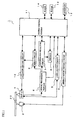
- Fig. 1 is a block diagram to show a structure of an optical disc apparatus according to the present embodiment.
- the optical disc apparatus 1 is set up to be capable of reproducing of information which is recorded on an optical disc (optical recording medium) 20. At this point the optical disc apparatus 1 can perform reproducing of information which is recorded in three kinds of optical discs of a BD, a DVD, and a CD.
- Reference numeral 2 designates a spindle motor and the optical disc 20 is held detachably by a chuck portion (not shown) which is set up above the spindle motor 2.
- the spindle motor 2 continuously rotates the optical disc 20 when reproducing of information which is recorded on the optical disc 20, is performed. Rotation control of the spindle motor 2 is performed by a spindle motor driving circuit 3.
- Reference numeral 4 designates an optical pickup, which irradiates a laser beam that is emitted from a light source to the optical disc 20 to make reading of information which is recorded on the optical disc 20, possible.
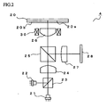
- Fig. 2 is a schematic diagram to show an optical system of the optical pickup 4. As shown in Fig. 2 , the optical pickup 4 is equipped with a first light source 21, a second light source 22, a dichroic prism 23, a collimator lens 24, a beam splitter 25, an objective lens 26, a condenser lens 27, and a photo detector 28.
- a structure of the optical system by which the optical pickup is structured is not limited to the above described example, and various modifications can be introduced, of course.
- the first light source 21 is a laser diode which emits a laser beam having single wavelength, and it emits the laser beam having a wavelength of 405 nm band which is used for a BD.
- the second light source 22 is a laser diode which is compatible to two wavelengths and can emit laser beams having two wavelengths, and it emits by switching the laser beams having a wavelength of 650 nm band which is used for a DVD and a wavelength of 780 nm band which is used for a CD.
- the laser beam which is emitted from the light sources 21 or 22, passes the dichroic prism 23, and is converted into parallel ray by the collimator lens 24.
- the laser beam passes the beam splitter 25 and is condensed by the objective lens 26 on a recording surface 20a on which information of the optical disc 20 is recorded.
- a reflected beam reflected by the recording surface 20a of the optical disc 20 passes the objective lens 26, is reflected by the beam splitter 25, and is condensed by the condenser lens 27 on a photo receiving region in the photo detector 28.
- the photo detector 28 converts received light information into electric signal.
- a laser driving circuit 5 performs switching of the first light source 21, and the second light source 22 in response to kind of the optical disc 20 which is loaded in the optical disc apparatus 1, and the laser driving circuit 5 also performs output control of the laser beam which is emitted from the light sources 21, 22 based on information from a photo receiving element (not shown) for front monitoring.
- a signal processing portion 6 is supplied electric signal from the photo detector 28 (See, Fig. 2 ), and performs processing of the supplied electric signal to generate RF signal, focus error signal (FE signal), and tracking error signal (TE signal).
- An information detecting circuit 7 performs processing of waveform equalization and the like on the RF signal which is supplied from the signal processing portion 6 to perform reading out of the information which is recorded on the optical disc 20.
- the information read out by the information detecting circuit 7 is demodulated by a decoder 8, and the demodulated reproducing signal is output to external devices such as a personal computer and the like via an interface 12.
- a servo circuit 9 performs generation of focus driving signal and tracking driving signal based on the FE signal and the TE signal which are generated by the signal processing portion 6.
- An actuator driving circuit 10 controls driving of objective lens driving device 30 (See, Fig. 2 ) on which the objective lens 26 (See, Fig. 2 ) is mounted, based on signal such as the focus driving signal, the tracking driving signal, and the like which are supplied from the servo circuit 9. A detail of the objective lens driving device 30 will be described later.
- a system control portion 11 includes a microcomputer to adequately perform control processes in response to required operations which are achieved by respective portions composing the optical disc apparatus 1.
- ROM 13 Read Only Memory
- RAM 14 Random Access Memory
- the RAM 14 is used as a working region for the system control portion 11 and it is made as a storing region for various kinds of data.
- Fig. 3 is a schematic plan view to show a structure of an objective lens driving device 30 when viewed from top.
- Fig. 4 is a schematic side view to show a structure of the objective lens driving device 30 when viewed from a side.
- an explanation on the objective lens driving device 30 according to the present embodiment will be given with reference to mainly Fig. 3 and Fig. 4 .
- the objective lens driving device 30 is mainly composed of a base member 31 which is made by metal having ferromagnetism and a lens holder 32 which is made by molded resin.
- a through hole (not shown) to pass a laser beam is formed, and above the through hole, the lens holder 32 detail of which will be described later is disposed.
- a pair of permanent magnets 33a, 33b which face each other with a predetermined distance so as to sandwich the lens holder 32, are disposed to stand.
- raised portions 31a, 31b which are formed by bending the base member 31, are disposed and the permanent magnets 33a, 33b and the raised portions 31a, 31b are fixed magnetically with each other.
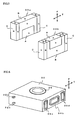
- Fig. 5 is a schematic perspective view to show a structure of permanent magnets 33a, 33b which are arranged in the objective lens driving device 30.
- Both of the permanent magnets 33a, 33b are multipole magnetized magnets in a rectangular parallelepiped shape.
- Both of the permanent magnets 33a, 33b are composed of a first region A which has a pole N in a rectangular parallelepiped shape, a second region B which is formed in a substantially U shaped cross section to surround the first region A and has a pole S, and a third region C which is composed of two rectangular parallelepiped shapes and formed to sandwich the second region B and has a pole N.
- the permanent magnet 33b is disposed to stand on the base member 31 in a state that the permanent magnet 33a is set in upside down.
- the first region A of the permanent magnet 33a faces to the second region B of the permanent magnet 33b and the first region A of the permanent magnet 33b faces to the second region B of the permanent magnet 33a.
- N-S polarity of the first region A and the second region B are inverse, magnetic field is generated substantially straightly from the permanent magnet 33a to the permanent magnet 33b or from the permanent magnet 33b to the permanent magnet 33a.
- directions of the magnetic fields do not become the state as above described.
- first region A and the third region C of the permanent magnets 33a, 33b are set in the pole N and the second region B is set in the pole S
- the present invention is not intended to limit this embodiment. That is to say, it is no problem that the first region A and the third region C are set in the pole S and the second region B is set in the pole N.
- a gel holder 36 which is formed by molded resin such as polycarbonate or the like is fixed, and in addition, a circuit board 39 is disposed to stand adjoining to outside of the gel holder 36.
- wires 37a, 37b, 37c, 37d which have conductivity are connected by soldering in two points of upper and lower directions in left and right sides of this circuit board 39, respectively.
- Each of these four wires 37a - 37d are inserted into through holes 38a, 38b, 38c, 38d which are formed in the gel holder 36, at corresponding positions to the connected positions to the circuit board 39, that is, two positions of upper and lower directions in left and right sides, respectively.
- wires 37a, 37c which are in the upper side are fixed in a state that they are electrically connected with the focusing coils 34a, 34b whose detail will be explained later, by soldering at wire support portions 32a, 32c which are set up in the lens holder 32.
- wires 37b, 37d which are in the lower side are fixed in a state that they are electrically connected with the tracking coils 35a - 35d whose detail will be explained later, by soldering at wire support portions 32b, 32d which are set up in the lens holder 32.
- number of wires to support the lens holder 32 is four, however, the present invention is not intended to limit this embodiment. That is to say, it is no problem that the number of wires is adequately changed as far as they can support properly the lens holder 32 and the lens holder 32 can be moved adequately.
- gel material which has silicone as main component, is filled.
- the gel material is formed by injecting low viscosity gel material (sol) into the respective through holes 38a - 38d of the gel holder 36 and irradiating it with ultraviolet rays for a predetermined period of time so that the material is cured into a gel state.
- This gel holder 36 plays a role of attenuating and suppressing vibration that is generated in each of the wires 37a - 37d in response to driving of the lens holder 32, by the gel material.
- a light path hole (not shown) which extends in perpendicular direction to a paper surface of Fig. 3 , is formed in central part of the lens holder 32 in order to pass the laser beam, and the objective lens 26 is held by an objective lens holding portion (not shown) which is set up in upper side of a cavity.
- the objective lens 26 which is mounted on the lens holder 32, is mounted such that an optical axis of it becomes parallel to a direction which is perpendicular to the paper surface of Fig. 3 .
- one focusing coil 34a and two tracking coils 35a, 35b are fixed on the lens holder 32 by an adhesive or the like. Further, on outside of side walls which face to the permanent magnet 33b among the side wall of the lens holder 32, also, one focusing coil 34b and two tracking coils 35c, 35d are fixed on the lens holder 32 by an adhesive or the like such that they are disposed in symmetrical position with the focusing coil 34a and two tracking coils 35a, 35b which are disposed on the outside of the side wall that face to the permanent magnet 33a.
- Fig. 6 is a schematic perspective view to show a structure of the lens holder 32 which is arranged in the objective lens driving device 30.
- the focusing coil 34b and the tracking coils 35c, 35d which are fixed on the lens holder 32, are disposed to align in a direction that is parallel to the tracking direction (direction shown by an arrow T in Fig. 6 ) with the focusing coil 34b being as a center. Further, though they are not shown in Fig. 6 , the focusing coil 34a and the tracking coils 35a, 35b are disposed similarly.
- the focusing coil 34a and the focusing coil 34b are connected by one wire as a whole, and the tracking coils 35a - 35d are also connected by one wire as a whole.
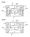
- Fig. 7A is a diagram to explain positional relation among the focusing coil 34a, the tracking coils 35a, 35b, and the permanent magnet 33a.
- Fig. 7B is a diagram to explain positional relation among the focusing coil 34b, the tracking coils 35c, 35d and the permanent magnet 33b.
- Fig. 7A and Fig. 7B are diagrams when they are viewed from the same direction that goes from below to above in Fig. 3 .
- the focusing coil 34b and the tracking coils 35c, 35d are shown in dotted line, because they exist in back side of the magnet.
- the focusing coil 34a is disposed such that one of its longer side overlaps with the first region A of the permanent magnet 33a, and the other longer side overlaps with the second region B of the permanent magnet 33a. Further, the focusing coil 34a is disposed such that a line which divides its shorter side in two equal parts and passes a center of the coil "O", overlaps with a border line of the first region A and the second region B of the permanent magnet 33a. In this case, one half of the shorter side of the focusing coil 34a overlaps with the first region A of the permanent magnet 33a and the other half of the shorter side overlaps with the second region B.
- the focusing coil 34b is also disposed with respect to the permanent magnet 33b in the same positional relation as that of the focusing coil 34a and the permanent magnet 33a as shown in Fig. 7B .
- the tracking coils 35a, 35b are disposed such that one of their longer side overlaps with the second region B of the permanent magnet 33a, and the other longer side overlaps with the third region C of the permanent magnet 33a. Further, the tracking coils 35a, 35b are disposed such that a line which divides their shorter side in two equal parts and passes a center of the coil "P", overlaps with a border line of the second region B and the third region C of the permanent magnet 33a. In this case, one half of the shorter side of the tracking coils 35a, 35b overlaps with the second region B of the permanent magnet 33a and the other half of the shorter side overlaps with the third region C.
- the tracking coils 35c, 35d are also disposed with respect to the permanent magnet 33b in the same positional relation as that of the tracking coils 35a, 35b and the permanent magnet 33a as shown in Fig. 7B .
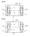
- Fig. 8A and Fig. 8B are diagrams to explain about driving forces which are generated in the focusing coils 34a, 34b and the tracking coils 35a - 35d that are arranged in the objective lens driving device 30.
- Fig. 8A is a diagram to explain about driving forces which are generated in a focusing coil 34a and tracking coils 35a, 35b
- Fig. 8B is a diagram to explain about driving forces which are generated in a focusing coil 34b and tracking coils 35c, 35d.
- Fig. 8A and Fig. 8B are similar drawings to Fig. 7A and Fig. 7B
- Fig. 8A and Fig. 8B are drawings that direction of electric current which passes the coils (dotted line arrow) and direction of driving forces which are generated in the respective coils (solid line arrow), are added.
- the focusing coils 34a, 34b are connected by one wire as above described, and the focusing coil 34a and the focusing coil 34b are wound such that driving forces having the same direction are generated in both of them when the electric current passes the focusing coils.
- the tracking coils 35a - 35d are connected by one wire as above described, and the respective tracking coils 35a - 35d are wound such that driving forces having the same direction are generated in the respective coils when the electric current passes the tracking coils.
- the objective lens 26 can be driven with the lens holder 32 because the driving forces having a certain direction are generated in the focusing coils 34a, 34b, and the tracking coils 35a - 35d, by passing electric current in the focusing coils 34a, 34b, and the tracking coils 35a - 35d.
- directions of electric currents which pass the focusing coils 34a, 34b, and the tracking coils 35a - 35d directions of the driving forces which are generated in the respective coils are changed, and moving direction of the lens holder 32 can be controlled.
- the permanent magnets 33a, 33b which are arranged in the objective lens driving device 30 according to the present embodiment, one of them is disposed upside down with respect to the other.
- the direction of the magnetic field of a part at which the focusing coils 34a, 34b are disposed is substantially orthogonal to side of the coils, it has a merit that magnetic forces of the permanent magnets 33a, 33b can be used effectively for the driving force of the focusing coils 34a, 34b.
- the driving forces which are generated in the tracking coils 35a - 35d become an unbalanced state and the objective lens is made tilted in case where the lens holder 32 is moved along the tracking direction.
- Fig. 9A and Fig. 9B explanation will be given with reference to Fig. 9A and Fig. 9B .
- Fig. 9A and Fig. 9B are diagrams to explain the driving forces which are generated in the tracking coils 35a - 35d in a state where the lens holder 32 in the objective lens driving device 30 is moved along the tracking direction.
- Fig. 9A is a diagram to explain the driving forces which are generated in the tracking coils 35a, 35b
- Fig. 9B is a diagram to explain the driving forces which are generated in the tracking coils 35c, 35d.
- solid line arrows shown in Fig. 9A and Fig. 9B designate forces which are generated in the coils, and lengths of them mean their magnitude schematically for the sake of convenience in explanation.
- dotted line arrows shown in Fig. 9A and Fig. 9B designate directions of electric currents which pass the tracking coils.
- the magnetic flux density distribution of upper side and lower side of the coils becomes different state in one of the two effective portions of the tracking coil 35a and the tracking coil 35c. Because of this, in the tracking coil 35a, the force that is generated by the electromagnetic force action in the upper side of the coil becomes larger than that in the lower side of the coil as shown in Fig. 9A . As a result, an unbalanced state is caused in the driving forces which are generated in the coils, and torque to rotate the lens holder 32 (See, Fig. 3 ) clockwise is generated.
- the force that is generated by the electromagnetic force action in the lower side of the coil becomes larger than that in the upper side of the coil.
- an unbalanced state is caused in the driving forces which are generated in the coils, and torque to rotate the lens holder 32 counterclockwise is generated. Therefore, two torques which have different rotational directions are generated in the lens holder 32 and both torques are cancelled with each other, rotation of the lens holder 32 (that is, tilting of the objective lens 26) can be suppressed.
- Fig. 10 and Fig. 11 are graphs to show a tilting characteristic of the objective lens 26 in the objective lens driving device 30 according to the present embodiment.
- Fig. 10 shows tilting angles (radial tilting angle) of the objective lens 26 in the radial direction (See, Fig. 3 ) when the objective lens 26 is moved ⁇ 0.4mm along the tracking direction in the states that offset in the focusing direction are +0.3mm, 0mm, and - 0.3mm.
- Fig. 11 shows the tilting angles (tangential tilting angle) of the objective lens 26 in the tangential direction (See, Fig. 3 ) when the objective lens 26 is moved ⁇ 0.4mm along the tracking direction in the states that offset in the focusing direction are +0.3mm, 0mm, and -0.3mm.
- both of the radial tilting and the tangential tilting can be suppressed small when the objective lend driving device 30 is driven. Therefore, when the objective lens driving device 30 according to the present embodiment is utilized, it becomes possible to perform reproducing of the optical disc 20 in a state that tilting of the objective lens 26 is suppressed small, as a result, the reproducing performance of the optical disc apparatus 1 can be improved.
- the optical disc apparatus 1 is an apparatus which can perform only reproducing of the optical disc.
- the apparatus is an optical disc apparatus which can perform both recording and reproducing, and in this case, tilting of the objective lens can be suppressed when recording is performed.
- the kind of the optical disc 20 to which the optical disc apparatus 1 is applied it is not limited to the kinds described in the present embodiment, and it can be changed adequately.
- the objective lens driving device By the objective lens driving device according to the present invention, tilting of the objective lens can be suppressed small. As a result, recording performance and reproducing performance of an optical disc apparatus in which an objective lens driving device according to the present invention is arranged, can be improved. Therefore, the objective lens driving device according to the present invention is very useful.
Landscapes
- Physics & Mathematics (AREA)
- Optics & Photonics (AREA)
- Optical Recording Or Reproduction (AREA)
Abstract
Description
- The present invention relates to an optical disc apparatus which performs reproducing of information recorded on an optical recording medium and recording of information on an optical recording medium, in particular, the present invention relates to an objective lens driving device which drives an objective lens that is arranged in the optical disc apparatus.
- An optical recording medium such as a compact disc (hereinafter referred to as a CD), or a digital versatile disc (hereinafter referred to as a DVD) has become popular. In addition, recently, to increase amount of information to be recorded on the optical recording medium, a study about high density recording on the optical recording medium is advanced, and for example, an optical recording medium which is made for high density recording such as a Blu-ray disc (hereinafter referred to as a BD) is being put to practical use. Recording and reproducing of these optical recording media are performed utilizing an optical disc apparatus.
- On the optical disc apparatus, an objective lens is arranged to condense a laser beam which is emitted from a light source on a recording surface of the optical recording medium. In case where recording or reproducing of the optical recording medium is performed utilizing the optical disc apparatus, position of the objective lens is lens is always kept on the recording surface of the optical recording medium despite of waving and the like of the optical recording medium, and that a position of the beam spot which is formed by condensing of the objective lens is not displaced from track which is formed on the optical recording medium.
- As above described, technology for high density recording on the optical recording medium is advanced, and based on this, high accuracy for driving accuracy of the objective lens driving device has also been required. Above all, in case where recording or reproducing of the optical recording medium is performed by the optical disc apparatus, it is necessary that the laser beam is input vertically to the recording surface of the optical recording medium from the objective lens, and it is required that a phenomenon in which the objective lens is tilted (tilting) because harmful torque is generated when the objective lens is driven by the objective lens driving device, is suppressed.
- About this point study has been conventionally performed, for example, technology is reported in
JP-A-2006-024266 JP-A-2002-237067 JP-A-2006-024266 - Further in
JP-A-2002-237067 - However, in case of the structure disclosed in
JP-A-2006-024266 - Further, all facing regions of the two magnets that are disposed to face each other for sandwiching the objective lens, have the same magnetic polarities. Therefore, a ratio of part where direction of the magnetic field that is formed by the magnets becomes slanted without being orthogonal to the focusing coil, is increased, it is conceivable that magnetic force of the magnet can not be effectively used.
- Further in case of the structure disclosed in
JP-A-2002-237067 - In view of the above described problems, it is an object of the present invention to provide an objective lens driving device in that the tilting of the objective lens by the harmful torque can be suppressed, and it is easy to manufacture. Further, it is another object of the present invention to provide an optical disc apparatus in which recording performance and reproducing performance are improved by including the above described objective lens driving device.
- To attain the above described object an objective lens driving device in accordance with the present invention includes: an objective lens; a lens holder which holds the objective lens; two magnets which are disposed facing each other to sandwich the lens holder; focusing coils which are fixed on the lens holder to generate driving force in focusing direction by electromagnetic force action with the magnets; tracking coils which are fixed on the lens holder to generate driving force in tracking direction by electromagnetic force action with the magnets; and an elastic supporting member which supports the lens holder in displaceable manner, and the device is characterized by a structure in which on a surface of the lens holder which faces to the magnet, one of the focusing coils and two of the tracking coils are set up to align in a direction that is parallel to the tracking direction with the focusing coil being as a center, the magnets are magnetized as multipole magnets such that two effective portions which are sides of the focusing coil that face each other to generate the driving force, act with magnetic fields which have respectively different directions, and such that two effective portions which are sides of the tracking coils that face each other to generate the driving force, act with magnetic fields which have respectively different directions, and the two magnets are disposed such that N-S polarity of them become inverse at a part of the surfaces which face each other.
- According to the present invention, the device has a structure that does not generate harmful torque as little as possible by specific designing for configuration of magnets. By the arrangement, it is possible to suppress tilting of the objective lens. Further, it does not happen that operation when the magnet is manufactured is burdensome in comparison with the conventional one because the magnets used are only multipole magnetized magnets which have specific configuration. As a result, it is easy to manufacture the objective lens driving device in accordance with the present invention. In addition, because the objective lens driving device according to the present invention is structured such that N-S polarity of the two magnets becomes inverse at a part of the surfaces which face each other, it is easy for magnetic field of the magnets to become substantially orthogonal to coils at the part. As a result, it is possible to increase efficiency of electromagnetic force action of the objective lens driving device.
- Further, it is preferable that the present invention has a structure in that the magnets are multipole magnetized magnets that are composed of a first region which has a rectangular parallelepiped shape, a second region which is formed in a substantially U shaped cross section to surround the first region and has an inverse N-S polarity with respect to the first region, and a third region that is composed of two rectangular parallelepiped shape regions which are formed to sandwich the second region and that has the same N-S polarity with respect to the first region in the objective lens driving device which is structured as above described.
- According to the present invention it is possible to realize a structure in that surfaces which face each other have inverse polarity at a part for two magnets by changing disposal direction of one kind of magnet. As a result, it is possible to manufacture an objective lens driving device that can suppress tilting of the objective lens with low cost.
- Still further the present invention is characterized by an optical disc apparatus in which an objective lens driving device that is structured as above described is arranged.
- According to the present invention, tilting of the objective lens can be suppressed when recording or reproducing is performed because in the optical disc apparatus the objective lens driving device which is structured as above described is arranged. As a result, it becomes possible to provide an optical disc apparatus which has improved recording performance and reproducing performance.
-
-
Fig. 1 is a block diagram to show a structure of an optical disc apparatus according to the present embodiment. -
Fig. 2 is a schematic diagram to show a structure of an optical system of an optical pickup which is arranged in the optical disc apparatus according to the present embodiment. -
Fig. 3 is a schematic plan view to show a structure of an objective lens driving device according to the present embodiment when viewed from top. -
Fig. 4 is a schematic side view to show a structure of the objective lens driving device according to the present embodiment when viewed from a side. -
Fig. 5 is a schematic perspective view to show a structure of a permanent magnet which is arranged in the objective lens driving device according to the present embodiment. -
Fig. 6 is a schematic perspective view to show a structure of a lens holder which is arranged in the objective lens driving device according to the present embodiment. -
Fig. 7A is a diagram to explain positional relation among a focusing coil, tracking coils, and a permanent magnet in the objective lens driving device according to the present embodiment. -
Fig. 7B is a diagram to explain positional relation among a focusing coil, tracking coils, and a permanent magnet in the objective lens driving device according to the present embodiment. -
Fig. 8A is a diagram to explain about driving forces which are generated in a focusing coil, and tracking coils that are arranged in the objective lens driving device according to the present embodiment. -
Fig. 8B is a diagram to explain about driving forces which are generated in a focusing coil, and tracking coils that are arranged in the objective lens driving device according to the present embodiment. -
Fig. 9A is a diagram to explain driving forces which are generated in the tracking coils in a state when the lens holder in the objective lens driving device according to the present embodiment is moved along a tracking direction. -
Fig. 9B is a diagram to explain driving forces which are generated in the tracking coils in a state when the lens holder in the objective lens driving device according to the present embodiment is moved along a tracking direction. -
Fig. 10 is a graph to show a tilting characteristic of the objective lens in the objective lens driving device according to the present embodiment. -
Fig. 11 is a graph to show a tilting characteristic of the objective lens in the objective lens driving device according to the present embodiment. - Hereinafter an embodiment of the present invention will be explained with reference to drawings. At this point the embodiment shown here is mere one example and the present invention is not limited to the embodiment shown here. In this explanation description will be given in order of a gross structure of an optical disc apparatus in which an objective lens driving device according to the present invention is arranged, and a structure of the objective lens driving device according to the present invention.
-
Fig. 1 is a block diagram to show a structure of an optical disc apparatus according to the present embodiment. Theoptical disc apparatus 1 is set up to be capable of reproducing of information which is recorded on an optical disc (optical recording medium) 20. At this point theoptical disc apparatus 1 can perform reproducing of information which is recorded in three kinds of optical discs of a BD, a DVD, and a CD. -
Reference numeral 2 designates a spindle motor and theoptical disc 20 is held detachably by a chuck portion (not shown) which is set up above thespindle motor 2. Thespindle motor 2 continuously rotates theoptical disc 20 when reproducing of information which is recorded on theoptical disc 20, is performed. Rotation control of thespindle motor 2 is performed by a spindlemotor driving circuit 3. -
Reference numeral 4 designates an optical pickup, which irradiates a laser beam that is emitted from a light source to theoptical disc 20 to make reading of information which is recorded on theoptical disc 20, possible.Fig. 2 is a schematic diagram to show an optical system of theoptical pickup 4. As shown inFig. 2 , theoptical pickup 4 is equipped with afirst light source 21, a secondlight source 22, adichroic prism 23, acollimator lens 24, abeam splitter 25, anobjective lens 26, acondenser lens 27, and aphoto detector 28. At this point, a structure of the optical system by which the optical pickup is structured, is not limited to the above described example, and various modifications can be introduced, of course. - The
first light source 21 is a laser diode which emits a laser beam having single wavelength, and it emits the laser beam having a wavelength of 405 nm band which is used for a BD. The secondlight source 22 is a laser diode which is compatible to two wavelengths and can emit laser beams having two wavelengths, and it emits by switching the laser beams having a wavelength of 650 nm band which is used for a DVD and a wavelength of 780 nm band which is used for a CD. - In the
optical pickup 4, the laser beam which is emitted from thelight sources dichroic prism 23, and is converted into parallel ray by thecollimator lens 24. The laser beam passes thebeam splitter 25 and is condensed by theobjective lens 26 on a recording surface 20a on which information of theoptical disc 20 is recorded. A reflected beam reflected by the recording surface 20a of theoptical disc 20 passes theobjective lens 26, is reflected by thebeam splitter 25, and is condensed by thecondenser lens 27 on a photo receiving region in thephoto detector 28. Thephoto detector 28 converts received light information into electric signal. - Now back to
Fig. 1 , alaser driving circuit 5 performs switching of thefirst light source 21, and the secondlight source 22 in response to kind of theoptical disc 20 which is loaded in theoptical disc apparatus 1, and thelaser driving circuit 5 also performs output control of the laser beam which is emitted from thelight sources - A
signal processing portion 6 is supplied electric signal from the photo detector 28 (See,Fig. 2 ), and performs processing of the supplied electric signal to generate RF signal, focus error signal (FE signal), and tracking error signal (TE signal). - An information detecting circuit 7 performs processing of waveform equalization and the like on the RF signal which is supplied from the
signal processing portion 6 to perform reading out of the information which is recorded on theoptical disc 20. The information read out by the information detecting circuit 7 is demodulated by adecoder 8, and the demodulated reproducing signal is output to external devices such as a personal computer and the like via aninterface 12. - A
servo circuit 9 performs generation of focus driving signal and tracking driving signal based on the FE signal and the TE signal which are generated by thesignal processing portion 6. - An
actuator driving circuit 10 controls driving of objective lens driving device 30 (See,Fig. 2 ) on which the objective lens 26 (See,Fig. 2 ) is mounted, based on signal such as the focus driving signal, the tracking driving signal, and the like which are supplied from theservo circuit 9. A detail of the objectivelens driving device 30 will be described later. - A system control portion 11 includes a microcomputer to adequately perform control processes in response to required operations which are achieved by respective portions composing the
optical disc apparatus 1. - In a system control portion 11, Read Only Memory (ROM) 13 and Random Access Memory (RAM) 14 are set up. In the ROM 13, various parameters and operating programs which are required for the system control portion 11 to achieve various processes, are stored. The
RAM 14 is used as a working region for the system control portion 11 and it is made as a storing region for various kinds of data. - Next, a structure of the objective
lens driving device 30 according to the present embodiment will be explained.Fig. 3 is a schematic plan view to show a structure of an objectivelens driving device 30 when viewed from top.Fig. 4 is a schematic side view to show a structure of the objectivelens driving device 30 when viewed from a side. Hereinafter an explanation on the objectivelens driving device 30 according to the present embodiment will be given with reference to mainlyFig. 3 and Fig. 4 . - The objective
lens driving device 30 is mainly composed of abase member 31 which is made by metal having ferromagnetism and alens holder 32 which is made by molded resin. In approximately center of thebase member 31, a through hole (not shown) to pass a laser beam is formed, and above the through hole, thelens holder 32 detail of which will be described later is disposed. Further, on thebase member 31, a pair of permanent magnets 33a, 33b which face each other with a predetermined distance so as to sandwich thelens holder 32, are disposed to stand. On outer surfaces of the permanent magnets 33a, 33b, raised portions 31a, 31b which are formed by bending thebase member 31, are disposed and the permanent magnets 33a, 33b and the raised portions 31a, 31b are fixed magnetically with each other. -
Fig. 5 is a schematic perspective view to show a structure of permanent magnets 33a, 33b which are arranged in the objectivelens driving device 30. Both of the permanent magnets 33a, 33b are multipole magnetized magnets in a rectangular parallelepiped shape. Both of the permanent magnets 33a, 33b are composed of a first region A which has a pole N in a rectangular parallelepiped shape, a second region B which is formed in a substantially U shaped cross section to surround the first region A and has a pole S, and a third region C which is composed of two rectangular parallelepiped shapes and formed to sandwich the second region B and has a pole N. - As shown in
Fig. 5 , the permanent magnet 33b is disposed to stand on thebase member 31 in a state that the permanent magnet 33a is set in upside down. As a result the first region A of the permanent magnet 33a faces to the second region B of the permanent magnet 33b and the first region A of the permanent magnet 33b faces to the second region B of the permanent magnet 33a. Because N-S polarity of the first region A and the second region B are inverse, magnetic field is generated substantially straightly from the permanent magnet 33a to the permanent magnet 33b or from the permanent magnet 33b to the permanent magnet 33a. At this point as for other portions, because the same poles face together, directions of the magnetic fields do not become the state as above described. - In this embodiment the first region A and the third region C of the permanent magnets 33a, 33b are set in the pole N and the second region B is set in the pole S, however, the present invention is not intended to limit this embodiment. That is to say, it is no problem that the first region A and the third region C are set in the pole S and the second region B is set in the pole N.
- On the
base member 31, outside of the raised portion 31b on inside of which the permanent magnets 33b is fixed magnetically, agel holder 36 which is formed by molded resin such as polycarbonate or the like is fixed, and in addition, acircuit board 39 is disposed to stand adjoining to outside of thegel holder 36. Each one end of wires 37a, 37b, 37c, 37d which have conductivity are connected by soldering in two points of upper and lower directions in left and right sides of thiscircuit board 39, respectively. Each of these four wires 37a - 37d are inserted into through holes 38a, 38b, 38c, 38d which are formed in thegel holder 36, at corresponding positions to the connected positions to thecircuit board 39, that is, two positions of upper and lower directions in left and right sides, respectively. - Other ends of the wires 37a, 37c which are in the upper side, are fixed in a state that they are electrically connected with the focusing coils 34a, 34b whose detail will be explained later, by soldering at wire support portions 32a, 32c which are set up in the
lens holder 32. Further, other ends of the wires 37b, 37d which are in the lower side, are fixed in a state that they are electrically connected with the tracking coils 35a - 35d whose detail will be explained later, by soldering atwire support portions 32b, 32d which are set up in thelens holder 32. By these arrangements, thelens holder 32 is supported in swingable manner on thebase member 31 by the respective wires 37a - 37d. - At this point in the present embodiment, number of wires to support the
lens holder 32 is four, however, the present invention is not intended to limit this embodiment. That is to say, it is no problem that the number of wires is adequately changed as far as they can support properly thelens holder 32 and thelens holder 32 can be moved adequately. - In addition, insides of each of the through holes 38a - 38d of the
gel holder 36 through which each of the wires 37a - 37d is inserted, gel material which has silicone as main component, is filled. At this point, the gel material is formed by injecting low viscosity gel material (sol) into the respective through holes 38a - 38d of thegel holder 36 and irradiating it with ultraviolet rays for a predetermined period of time so that the material is cured into a gel state. Thisgel holder 36 plays a role of attenuating and suppressing vibration that is generated in each of the wires 37a - 37d in response to driving of thelens holder 32, by the gel material. - A light path hole (not shown) which extends in perpendicular direction to a paper surface of
Fig. 3 , is formed in central part of thelens holder 32 in order to pass the laser beam, and theobjective lens 26 is held by an objective lens holding portion (not shown) which is set up in upper side of a cavity. At this point theobjective lens 26 which is mounted on thelens holder 32, is mounted such that an optical axis of it becomes parallel to a direction which is perpendicular to the paper surface ofFig. 3 . - On outside of side wall which faces to the permanent magnet 33a among the side walls of the
lens holder 32, one focusing coil 34a and two tracking coils 35a, 35b are fixed on thelens holder 32 by an adhesive or the like. Further, on outside of side walls which face to the permanent magnet 33b among the side wall of thelens holder 32, also, one focusing coil 34b and two tracking coils 35c, 35d are fixed on thelens holder 32 by an adhesive or the like such that they are disposed in symmetrical position with the focusing coil 34a and two tracking coils 35a, 35b which are disposed on the outside of the side wall that face to the permanent magnet 33a. -
Fig. 6 is a schematic perspective view to show a structure of thelens holder 32 which is arranged in the objectivelens driving device 30. As shown inFig. 6 , the focusing coil 34b and the tracking coils 35c, 35d which are fixed on thelens holder 32, are disposed to align in a direction that is parallel to the tracking direction (direction shown by an arrow T inFig. 6 ) with the focusing coil 34b being as a center. Further, though they are not shown inFig. 6 , the focusing coil 34a and the tracking coils 35a, 35b are disposed similarly. - At this point, the focusing coil 34a and the focusing coil 34b are connected by one wire as a whole, and the tracking coils 35a - 35d are also connected by one wire as a whole.
- Next, positional relation among the focusing coils 34a, 34b, the tracking coils 35a - 35d, and the permanent magnets 33a, 33b will be explained with reference to
Fig. 7A and Fig. 7B. Fig. 7A is a diagram to explain positional relation among the focusing coil 34a, the tracking coils 35a, 35b, and the permanent magnet 33a.Fig. 7B is a diagram to explain positional relation among the focusing coil 34b, the tracking coils 35c, 35d and the permanent magnet 33b. At this pointFig. 7A and Fig. 7B are diagrams when they are viewed from the same direction that goes from below to above inFig. 3 . Further inFig. 7B , the focusing coil 34b and the tracking coils 35c, 35d are shown in dotted line, because they exist in back side of the magnet. - As shown in
Fig. 7A , the focusing coil 34a is disposed such that one of its longer side overlaps with the first region A of the permanent magnet 33a, and the other longer side overlaps with the second region B of the permanent magnet 33a. Further, the focusing coil 34a is disposed such that a line which divides its shorter side in two equal parts and passes a center of the coil "O", overlaps with a border line of the first region A and the second region B of the permanent magnet 33a. In this case, one half of the shorter side of the focusing coil 34a overlaps with the first region A of the permanent magnet 33a and the other half of the shorter side overlaps with the second region B. - At this point, the focusing coil 34b is also disposed with respect to the permanent magnet 33b in the same positional relation as that of the focusing coil 34a and the permanent magnet 33a as shown in
Fig. 7B . - Further as shown in
Fig. 7A , the tracking coils 35a, 35b are disposed such that one of their longer side overlaps with the second region B of the permanent magnet 33a, and the other longer side overlaps with the third region C of the permanent magnet 33a. Further, the tracking coils 35a, 35b are disposed such that a line which divides their shorter side in two equal parts and passes a center of the coil "P", overlaps with a border line of the second region B and the third region C of the permanent magnet 33a. In this case, one half of the shorter side of the tracking coils 35a, 35b overlaps with the second region B of the permanent magnet 33a and the other half of the shorter side overlaps with the third region C. - At this point, the tracking coils 35c, 35d are also disposed with respect to the permanent magnet 33b in the same positional relation as that of the tracking coils 35a, 35b and the permanent magnet 33a as shown in
Fig. 7B . - Next, operation of the objective
lens driving device 30 structured as above described, will be explained.Fig. 8A and Fig. 8B are diagrams to explain about driving forces which are generated in the focusing coils 34a, 34b and the tracking coils 35a - 35d that are arranged in the objectivelens driving device 30.Fig. 8A is a diagram to explain about driving forces which are generated in a focusing coil 34a and tracking coils 35a, 35b, andFig. 8B is a diagram to explain about driving forces which are generated in a focusing coil 34b and tracking coils 35c, 35d. At this pointFig. 8A and Fig. 8B are similar drawings toFig. 7A and Fig. 7B , andFig. 8A and Fig. 8B are drawings that direction of electric current which passes the coils (dotted line arrow) and direction of driving forces which are generated in the respective coils (solid line arrow), are added. - An explanation will be given about driving forces which are generated in the focusing coils 34a, 34b and the tracking coils 35a - 35d when the electric current passes in the direction shown in
Fig. 8A and Fig. 8B . - First, explanation about the driving force that is generated in the focusing coils 34a, 34b will be given. Though directions of the electric current which passes the coils become inverse between upper side and lower side of the longer side of the focusing coils 34a, 34b, forces (force by electromagnetic force action) of the same direction (direction shown with arrow in the drawing) are generated according to Fleming's left hand rule because directions of magnetic fields which act on the respective longer sides are inverse. On the other hand, as for the shorter sides of the focusing coils 34a, 34b, no driving force is generated in the shorter sides because the driving forces that are generated in the shorter sides which face each other, of the respective coils, have inverse directions and the forces that are generated in the shorter sides of the coils are cancelled as a whole. That is to say, in the focusing coils 34a, 34b, the longer sides functions as an effective portion which generates the driving forces, and by these, driving force in the focusing direction F (See,
Fig. 4 ) is generated. - At this point the focusing coils 34a, 34b are connected by one wire as above described, and the focusing coil 34a and the focusing coil 34b are wound such that driving forces having the same direction are generated in both of them when the electric current passes the focusing coils.
- Further in the tracking coils 35a -35d, though directions of the electric current which passes the coils become inverse between left side and right side of the longer side, forces (force by electromagnetic force action) of the same direction (direction shown with arrow in the drawing) along the tracking direction are generated according to Fleming's left hand rule because directions of magnetic fields which act on the respective longer sides are inverse. On the other hand, as for the shorter sides of the tracking coils 35a - 35d , no driving force is generated in the shorter sides because the driving forces that are generated in the shorter sides which face each other, of the respective coils, have inverse directions and the forces that are generated in the shorter sides of the coils are cancelled as a whole. That is to say, in the tracking coils 35a - 35d, the longer sides functions as an effective portion which generates the driving forces, and by these, driving force in the tracking direction T (See,
Fig. 3 ) is generated. - At this point the tracking coils 35a - 35d are connected by one wire as above described, and the respective tracking coils 35a - 35d are wound such that driving forces having the same direction are generated in the respective coils when the electric current passes the tracking coils.
- As above described, in the objective
lens driving device 30, theobjective lens 26 can be driven with thelens holder 32 because the driving forces having a certain direction are generated in the focusing coils 34a, 34b, and the tracking coils 35a - 35d, by passing electric current in the focusing coils 34a, 34b, and the tracking coils 35a - 35d. As a result by changing directions of electric currents which pass the focusing coils 34a, 34b, and the tracking coils 35a - 35d, directions of the driving forces which are generated in the respective coils are changed, and moving direction of thelens holder 32 can be controlled. - As above described, for the permanent magnets 33a, 33b which are arranged in the objective
lens driving device 30 according to the present embodiment, one of them is disposed upside down with respect to the other. In this case because the direction of the magnetic field of a part at which the focusing coils 34a, 34b are disposed, is substantially orthogonal to side of the coils, it has a merit that magnetic forces of the permanent magnets 33a, 33b can be used effectively for the driving force of the focusing coils 34a, 34b. Further, it can be prevented that the driving forces which are generated in the tracking coils 35a - 35d, become an unbalanced state and the objective lens is made tilted in case where thelens holder 32 is moved along the tracking direction. About the latter case, explanation will be given with reference toFig. 9A and Fig. 9B . -
Fig. 9A and Fig. 9B are diagrams to explain the driving forces which are generated in the tracking coils 35a - 35d in a state where thelens holder 32 in the objectivelens driving device 30 is moved along the tracking direction.Fig. 9A is a diagram to explain the driving forces which are generated in the tracking coils 35a, 35b, andFig. 9B is a diagram to explain the driving forces which are generated in the tracking coils 35c, 35d. At this point solid line arrows shown inFig. 9A and Fig. 9B designate forces which are generated in the coils, and lengths of them mean their magnitude schematically for the sake of convenience in explanation. Further, dotted line arrows shown inFig. 9A and Fig. 9B designate directions of electric currents which pass the tracking coils. - When the
lens holder 32 is moved along the tracking direction (inFig. 9A and Fig. 9B a state is shown that thelens holder 32 shown inFig. 3 is moved in right direction) and the effective portions of the tracking coils 35a - 35d come closer to borders of regions which have different N-S polarities, or come closer to end portion of the magnet, forces that are generated in the coils at those parts by the electromagnetic force action, become smaller because of decrease in the magnetic flux density distribution. - In case of the present embodiment, when the state shown in
Fig. 9A and Fig. 9B is realized, the magnetic flux density distribution of upper side and lower side of the coils becomes different state in one of the two effective portions of the tracking coil 35a and the tracking coil 35c. Because of this, in the tracking coil 35a, the force that is generated by the electromagnetic force action in the upper side of the coil becomes larger than that in the lower side of the coil as shown inFig. 9A . As a result, an unbalanced state is caused in the driving forces which are generated in the coils, and torque to rotate the lens holder 32 (See,Fig. 3 ) clockwise is generated. - On the other hand in the tracking coil 35c, as shown in
Fig. 9B , the force that is generated by the electromagnetic force action in the lower side of the coil becomes larger than that in the upper side of the coil. As a result, an unbalanced state is caused in the driving forces which are generated in the coils, and torque to rotate thelens holder 32 counterclockwise is generated. Therefore, two torques which have different rotational directions are generated in thelens holder 32 and both torques are cancelled with each other, rotation of the lens holder 32 (that is, tilting of the objective lens 26) can be suppressed. - At this point, in case where a structure in that the permanent magnet 33b is rotated inversely with respect to the permanent magnet 33a such as the present embodiment, is not employed, rotating torques which are caused by the unbalanced state of forces that are generated in the tracking coil 35a and the tracking coil 35c, have the same direction and they rotate the
lens holder 32, as a result, theobjective lens 26 is tilted. -
Fig. 10 and Fig. 11 are graphs to show a tilting characteristic of theobjective lens 26 in the objectivelens driving device 30 according to the present embodiment.Fig. 10 shows tilting angles (radial tilting angle) of theobjective lens 26 in the radial direction (See,Fig. 3 ) when theobjective lens 26 is moved ±0.4mm along the tracking direction in the states that offset in the focusing direction are +0.3mm, 0mm, and - 0.3mm.Fig. 11 shows the tilting angles (tangential tilting angle) of theobjective lens 26 in the tangential direction (See,Fig. 3 ) when theobjective lens 26 is moved ±0.4mm along the tracking direction in the states that offset in the focusing direction are +0.3mm, 0mm, and -0.3mm. - As shown in
Fig. 10 and Fig. 11 , in the objectivelens driving device 30 according to the present embodiment, both of the radial tilting and the tangential tilting can be suppressed small when the objective lend drivingdevice 30 is driven. Therefore, when the objectivelens driving device 30 according to the present embodiment is utilized, it becomes possible to perform reproducing of theoptical disc 20 in a state that tilting of theobjective lens 26 is suppressed small, as a result, the reproducing performance of theoptical disc apparatus 1 can be improved. - In the embodiment described above, the
optical disc apparatus 1 is an apparatus which can perform only reproducing of the optical disc. However, it is of course no problem that the apparatus is an optical disc apparatus which can perform both recording and reproducing, and in this case, tilting of the objective lens can be suppressed when recording is performed. Further, it is needless to say that as for the kind of theoptical disc 20 to which theoptical disc apparatus 1 is applied, it is not limited to the kinds described in the present embodiment, and it can be changed adequately. - By the objective lens driving device according to the present invention, tilting of the objective lens can be suppressed small. As a result, recording performance and reproducing performance of an optical disc apparatus in which an objective lens driving device according to the present invention is arranged, can be improved. Therefore, the objective lens driving device according to the present invention is very useful.
Claims (3)
- An objective lens driving device comprising:an objective lens;a lens holder which holds the objective lens;two magnets which are disposed facing each other to sandwich the lens holder;focusing coils which are fixed on the lens holder to generate driving force in focusing direction by electromagnetic force action with the magnets;tracking coils which are fixed on the lens holder to generate driving force in tracking direction by electromagnetic force action with the magnets; andan elastic supporting member which supports the lens holder in movable manner, characterized in thaton a surface of the lens holder which faces to the magnet, one of the focusing coils and two of the tracking coils are set up to align in a direction that is parallel to the tracking direction with the focusing coil being as a center,the magnets are magnetized as multipole magnets such that two effective portions which are sides of the focusing coil that face each other to generate the driving force, act with different direction magnetic fields respectively, and such that two effective portions which are sides of the tracking coils that face each other to generate the driving force, act with different direction magnetic fields respectively, andthe two magnets are disposed such that N-S polarity of them becomes inverse at a part of the surfaces which face each other.
- The objective lens driving device according to claim 1, characterized in that the magnets are multipole magnetized magnets that are composed of a first region which has a rectangular parallelepiped shape, a second region which is formed in a substantially U shaped cross section to surround the first region and has an inverse N-S polarity with respect to the first region, and a third region that is composed of two rectangular parallelepiped shape regions which are formed to sandwich the second region and that has the same N-S polarity with respect to the first region.
- An optical disc apparatus in which the objective lens driving device according to claim 1 or claim 2 is arranged.
Applications Claiming Priority (1)
| Application Number | Priority Date | Filing Date | Title |
|---|---|---|---|
| JP2006345282A JP2008159126A (en) | 2006-12-22 | 2006-12-22 | Objective lens driving device and optical disc apparatus |
Publications (3)
| Publication Number | Publication Date |
|---|---|
| EP1936617A2 true EP1936617A2 (en) | 2008-06-25 |
| EP1936617A3 EP1936617A3 (en) | 2008-11-26 |
| EP1936617B1 EP1936617B1 (en) | 2010-07-07 |
Family
ID=39167632
Family Applications (1)
| Application Number | Title | Priority Date | Filing Date |
|---|---|---|---|
| EP07024433A Not-in-force EP1936617B1 (en) | 2006-12-22 | 2007-12-17 | Objective lens driving device and optical disc apparatus |
Country Status (4)
| Country | Link |
|---|---|
| US (1) | US7835234B2 (en) |
| EP (1) | EP1936617B1 (en) |
| JP (1) | JP2008159126A (en) |
| DE (1) | DE602007007563D1 (en) |
Citations (4)
| Publication number | Priority date | Publication date | Assignee | Title |
|---|---|---|---|---|
| EP1124222A2 (en) | 2000-02-08 | 2001-08-16 | Pioneer Corporation | Apparatus for driving a lens for use with a disk player |
| JP2002237067A (en) | 2001-02-14 | 2002-08-23 | Ricoh Co Ltd | Objective lens drive |
| WO2005066945A1 (en) | 2004-01-12 | 2005-07-21 | Mempile Inc. | Lens actuator assembly for optical head |
| JP2006024266A (en) | 2004-07-07 | 2006-01-26 | Toshiba Corp | Objective lens actuator and optical disk apparatus |
Family Cites Families (6)
| Publication number | Priority date | Publication date | Assignee | Title |
|---|---|---|---|---|
| US6344936B1 (en) * | 1999-09-29 | 2002-02-05 | Matsushita Electric Industrial Co., Ltd. | Objective lens driving apparatus |
| JP2003346359A (en) * | 2002-05-27 | 2003-12-05 | Pioneer Electronic Corp | Coil substrate for lens driving device and lens driving device |
| JP2004005813A (en) * | 2002-05-31 | 2004-01-08 | Tdk Corp | Optical head device and optical reproducing device using the same |
| JP2004295932A (en) * | 2003-03-25 | 2004-10-21 | Funai Electric Co Ltd | Objective lens driving device for optical head |
| KR20050070699A (en) * | 2003-12-30 | 2005-07-07 | 삼성전자주식회사 | Actuator for optical pickup |
| TWI322424B (en) * | 2005-12-27 | 2010-03-21 | Ind Tech Res Inst | Objective lens deiving apparatus |
-
2006
- 2006-12-22 JP JP2006345282A patent/JP2008159126A/en active Pending
-
2007
- 2007-12-17 EP EP07024433A patent/EP1936617B1/en not_active Not-in-force
- 2007-12-17 DE DE602007007563T patent/DE602007007563D1/en active Active
- 2007-12-19 US US12/000,933 patent/US7835234B2/en not_active Expired - Fee Related
Patent Citations (4)
| Publication number | Priority date | Publication date | Assignee | Title |
|---|---|---|---|---|
| EP1124222A2 (en) | 2000-02-08 | 2001-08-16 | Pioneer Corporation | Apparatus for driving a lens for use with a disk player |
| JP2002237067A (en) | 2001-02-14 | 2002-08-23 | Ricoh Co Ltd | Objective lens drive |
| WO2005066945A1 (en) | 2004-01-12 | 2005-07-21 | Mempile Inc. | Lens actuator assembly for optical head |
| JP2006024266A (en) | 2004-07-07 | 2006-01-26 | Toshiba Corp | Objective lens actuator and optical disk apparatus |
Also Published As
| Publication number | Publication date |
|---|---|
| US7835234B2 (en) | 2010-11-16 |
| EP1936617B1 (en) | 2010-07-07 |
| US20080259774A1 (en) | 2008-10-23 |
| JP2008159126A (en) | 2008-07-10 |
| DE602007007563D1 (en) | 2010-08-19 |
| EP1936617A3 (en) | 2008-11-26 |
Similar Documents
| Publication | Publication Date | Title |
|---|---|---|
| US7054078B2 (en) | Objective lens driving device | |
| JP4012809B2 (en) | Objective lens drive | |
| KR20060136355A (en) | Optical pickup and optical disk device | |
| KR20070000385A (en) | Optical pickup and optical disk device | |
| EP1936617B1 (en) | Objective lens driving device and optical disc apparatus | |
| JP2003331443A (en) | Objective lens driving device and optical head having the same | |
| EP1936616B1 (en) | Objective lens driving device, assembling method for the same and optical disc apparatus | |
| KR100688597B1 (en) | Optical pickup actuator with high force and optical recording / reproducing device using the same | |
| EP1717800A2 (en) | Optical pickup actuator and optical recording and/or reproducing apparatus | |
| EP2012318B1 (en) | Lens holder for optical pickup and optical pickup having same | |
| JP2002260258A (en) | Objective lens driving device and disk device having the same | |
| KR100444563B1 (en) | 2-axis actuator and optical disk device | |
| KR20060083889A (en) | Objective lens drive, optical pickup and optical disk device | |
| JP2005332518A (en) | Optical component triaxial drive device and recording / reproducing device using the same | |
| JP4533322B2 (en) | Optical pickup | |
| JP4508134B2 (en) | Objective lens actuator and optical pickup device having the same | |
| JPH09237428A (en) | Biaxial actuator and optical disk device | |
| JP4564944B2 (en) | Optical pickup | |
| CN100361206C (en) | Optical head and disc device | |
| JP2009245476A (en) | Objective lens actuator and optical disk device | |
| JP2009146531A (en) | Lens holder for optical pickup and optical pickup provided with the same | |
| JP2010040067A (en) | Objective lens actuator and optical disk device | |
| JP2007234112A (en) | Objective lens actuator and information recording / reproducing apparatus | |
| JPH01204232A (en) | Lens actuator | |
| JP2007213694A (en) | Optical pickup device |
Legal Events
| Date | Code | Title | Description |
|---|---|---|---|
| PUAI | Public reference made under article 153(3) epc to a published international application that has entered the european phase |
Free format text: ORIGINAL CODE: 0009012 |
|
| AK | Designated contracting states |
Kind code of ref document: A2 Designated state(s): AT BE BG CH CY CZ DE DK EE ES FI FR GB GR HU IE IS IT LI LT LU LV MC MT NL PL PT RO SE SI SK TR |
|
| AX | Request for extension of the european patent |
Extension state: AL BA HR MK RS |
|
| PUAL | Search report despatched |
Free format text: ORIGINAL CODE: 0009013 |
|
| AK | Designated contracting states |
Kind code of ref document: A3 Designated state(s): AT BE BG CH CY CZ DE DK EE ES FI FR GB GR HU IE IS IT LI LT LU LV MC MT NL PL PT RO SE SI SK TR |
|
| AX | Request for extension of the european patent |
Extension state: AL BA HR MK RS |
|
| 17P | Request for examination filed |
Effective date: 20090430 |
|
| AKX | Designation fees paid |
Designated state(s): DE FR GB |
|
| GRAP | Despatch of communication of intention to grant a patent |
Free format text: ORIGINAL CODE: EPIDOSNIGR1 |
|
| GRAS | Grant fee paid |
Free format text: ORIGINAL CODE: EPIDOSNIGR3 |
|
| GRAA | (expected) grant |
Free format text: ORIGINAL CODE: 0009210 |
|
| AK | Designated contracting states |
Kind code of ref document: B1 Designated state(s): DE FR GB |
|
| REG | Reference to a national code |
Ref country code: GB Ref legal event code: FG4D |
|
| REF | Corresponds to: |
Ref document number: 602007007563 Country of ref document: DE Date of ref document: 20100819 Kind code of ref document: P |
|
| PLBE | No opposition filed within time limit |
Free format text: ORIGINAL CODE: 0009261 |
|
| STAA | Information on the status of an ep patent application or granted ep patent |
Free format text: STATUS: NO OPPOSITION FILED WITHIN TIME LIMIT |
|
| 26N | No opposition filed |
Effective date: 20110408 |
|
| REG | Reference to a national code |
Ref country code: DE Ref legal event code: R097 Ref document number: 602007007563 Country of ref document: DE Effective date: 20110408 |
|
| REG | Reference to a national code |
Ref country code: FR Ref legal event code: PLFP Year of fee payment: 9 |
|
| PGFP | Annual fee paid to national office [announced via postgrant information from national office to epo] |
Ref country code: DE Payment date: 20151208 Year of fee payment: 9 Ref country code: GB Payment date: 20151216 Year of fee payment: 9 |
|
| PGFP | Annual fee paid to national office [announced via postgrant information from national office to epo] |
Ref country code: FR Payment date: 20151110 Year of fee payment: 9 |
|
| REG | Reference to a national code |
Ref country code: DE Ref legal event code: R119 Ref document number: 602007007563 Country of ref document: DE |
|
| GBPC | Gb: european patent ceased through non-payment of renewal fee |
Effective date: 20161217 |
|
| REG | Reference to a national code |
Ref country code: FR Ref legal event code: ST Effective date: 20170831 |
|
| PG25 | Lapsed in a contracting state [announced via postgrant information from national office to epo] |
Ref country code: FR Free format text: LAPSE BECAUSE OF NON-PAYMENT OF DUE FEES Effective date: 20170102 |
|
| PG25 | Lapsed in a contracting state [announced via postgrant information from national office to epo] |
Ref country code: DE Free format text: LAPSE BECAUSE OF NON-PAYMENT OF DUE FEES Effective date: 20170701 Ref country code: GB Free format text: LAPSE BECAUSE OF NON-PAYMENT OF DUE FEES Effective date: 20161217 |