EP1936435B1 - Optical apparatus with unit for correcting blur of captured image caused by displacement of optical apparatus in optical-axis direction - Google Patents
Optical apparatus with unit for correcting blur of captured image caused by displacement of optical apparatus in optical-axis direction Download PDFInfo
- Publication number
- EP1936435B1 EP1936435B1 EP07123874A EP07123874A EP1936435B1 EP 1936435 B1 EP1936435 B1 EP 1936435B1 EP 07123874 A EP07123874 A EP 07123874A EP 07123874 A EP07123874 A EP 07123874A EP 1936435 B1 EP1936435 B1 EP 1936435B1
- Authority
- EP
- European Patent Office
- Prior art keywords
- image
- focus
- image pickup
- optical
- displacement
- Prior art date
- Legal status (The legal status is an assumption and is not a legal conclusion. Google has not performed a legal analysis and makes no representation as to the accuracy of the status listed.)
- Expired - Fee Related
Links
Images


Classifications
-
- G—PHYSICS
- G03—PHOTOGRAPHY; CINEMATOGRAPHY; ANALOGOUS TECHNIQUES USING WAVES OTHER THAN OPTICAL WAVES; ELECTROGRAPHY; HOLOGRAPHY
- G03B—APPARATUS OR ARRANGEMENTS FOR TAKING PHOTOGRAPHS OR FOR PROJECTING OR VIEWING THEM; APPARATUS OR ARRANGEMENTS EMPLOYING ANALOGOUS TECHNIQUES USING WAVES OTHER THAN OPTICAL WAVES; ACCESSORIES THEREFOR
- G03B17/00—Details of cameras or camera bodies; Accessories therefor
-
- G—PHYSICS
- G02—OPTICS
- G02B—OPTICAL ELEMENTS, SYSTEMS OR APPARATUS
- G02B7/00—Mountings, adjusting means, or light-tight connections, for optical elements
- G02B7/28—Systems for automatic generation of focusing signals
-
- H—ELECTRICITY
- H04—ELECTRIC COMMUNICATION TECHNIQUE
- H04N—PICTORIAL COMMUNICATION, e.g. TELEVISION
- H04N19/00—Methods or arrangements for coding, decoding, compressing or decompressing digital video signals
- H04N19/50—Methods or arrangements for coding, decoding, compressing or decompressing digital video signals using predictive coding
- H04N19/503—Methods or arrangements for coding, decoding, compressing or decompressing digital video signals using predictive coding involving temporal prediction
- H04N19/51—Motion estimation or motion compensation
-
- H—ELECTRICITY
- H04—ELECTRIC COMMUNICATION TECHNIQUE
- H04N—PICTORIAL COMMUNICATION, e.g. TELEVISION
- H04N23/00—Cameras or camera modules comprising electronic image sensors; Control thereof
- H04N23/60—Control of cameras or camera modules
- H04N23/68—Control of cameras or camera modules for stable pick-up of the scene, e.g. compensating for camera body vibrations
- H04N23/681—Motion detection
- H04N23/6812—Motion detection based on additional sensors, e.g. acceleration sensors
-
- H—ELECTRICITY
- H04—ELECTRIC COMMUNICATION TECHNIQUE
- H04N—PICTORIAL COMMUNICATION, e.g. TELEVISION
- H04N23/00—Cameras or camera modules comprising electronic image sensors; Control thereof
- H04N23/60—Control of cameras or camera modules
- H04N23/68—Control of cameras or camera modules for stable pick-up of the scene, e.g. compensating for camera body vibrations
- H04N23/682—Vibration or motion blur correction
- H04N23/683—Vibration or motion blur correction performed by a processor, e.g. controlling the readout of an image memory
-
- H—ELECTRICITY
- H04—ELECTRIC COMMUNICATION TECHNIQUE
- H04N—PICTORIAL COMMUNICATION, e.g. TELEVISION
- H04N23/00—Cameras or camera modules comprising electronic image sensors; Control thereof
- H04N23/60—Control of cameras or camera modules
- H04N23/68—Control of cameras or camera modules for stable pick-up of the scene, e.g. compensating for camera body vibrations
- H04N23/682—Vibration or motion blur correction
- H04N23/684—Vibration or motion blur correction performed by controlling the image sensor readout, e.g. by controlling the integration time
-
- H—ELECTRICITY
- H04—ELECTRIC COMMUNICATION TECHNIQUE
- H04N—PICTORIAL COMMUNICATION, e.g. TELEVISION
- H04N23/00—Cameras or camera modules comprising electronic image sensors; Control thereof
- H04N23/60—Control of cameras or camera modules
- H04N23/68—Control of cameras or camera modules for stable pick-up of the scene, e.g. compensating for camera body vibrations
- H04N23/682—Vibration or motion blur correction
- H04N23/685—Vibration or motion blur correction performed by mechanical compensation
- H04N23/687—Vibration or motion blur correction performed by mechanical compensation by shifting the lens or sensor position
-
- H—ELECTRICITY
- H04—ELECTRIC COMMUNICATION TECHNIQUE
- H04N—PICTORIAL COMMUNICATION, e.g. TELEVISION
- H04N23/00—Cameras or camera modules comprising electronic image sensors; Control thereof
- H04N23/70—Circuitry for compensating brightness variation in the scene
- H04N23/76—Circuitry for compensating brightness variation in the scene by influencing the image signals
-
- G—PHYSICS
- G03—PHOTOGRAPHY; CINEMATOGRAPHY; ANALOGOUS TECHNIQUES USING WAVES OTHER THAN OPTICAL WAVES; ELECTROGRAPHY; HOLOGRAPHY
- G03B—APPARATUS OR ARRANGEMENTS FOR TAKING PHOTOGRAPHS OR FOR PROJECTING OR VIEWING THEM; APPARATUS OR ARRANGEMENTS EMPLOYING ANALOGOUS TECHNIQUES USING WAVES OTHER THAN OPTICAL WAVES; ACCESSORIES THEREFOR
- G03B2217/00—Details of cameras or camera bodies; Accessories therefor
- G03B2217/005—Blur detection
Definitions
- the present invention relates to a technique of improving deterioration of a captured image caused by hand shake during image captured by an optical apparatus such as a digital camera.
- the present invention relates to a technique of reducing image blurring caused, for example, by hand movement in the optical-axis direction during macro image-capturing.
- An optical apparatus such as a camera or an interchangeable lens is often provided with an image stabilizer that improves an image blur caused by hand-induced shake or the like.
- the hand-induced shake is a vibration normally having a frequency ranging from 1 to 10 Hz.
- the image stabilizer mainly corrects image blurring caused by vibrations having such a frequency.
- the vibration of the optical apparatus is detected.
- a technique like optical image-stabilization or electronic image-stabilization is used.
- Optical image-stabilization shifts a correction lens in a plane orthogonal to the optical axis in accordance with the detected vibration.
- the electronic image-stabilization varies an area, from which data is output as an image, from within the total pixel area of the imaging element.
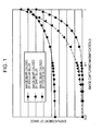
- Fig. 1 is a graph showing the effects of the blurs. Fig. 1 plots image-capturing magnification in the x direction and displacement of the image in an image plane due to blurring in the y direction.
- the above-mentioned electronic image-stabilization is frequently used in apparatus for recording movies, such as a video camera.
- the present invention can provide an optical apparatus capable of providing an image having reduced focus blurring caused by hand-induced shake without using an auto-focusing device or a mechanical device for accurately following the blur.
- the present invention provides an optical apparatus as specified in claims 1 to 9.
- Fig. 1 is a graph showing effects of image-capturing magnifications and motion blurs caused by hand shake to an image plane.
- Fig. 2 is a block diagram showing the function of a digital single-lens reflex camera with an interchangeable lens according to a first embodiment of the present invention.
- Fig. 3 is a first graph showing the relationship between blur in an optical-axis direction and exposure according to the first embodiment of the present invention.
- Fig. 4 is a second graph showing the relationship between blur in the optical-axis direction and the exposure according to the first embodiment of the present invention.
- Fig. 5 is an illustration schematically showing image combining according to the first embodiment of the present invention.
- Fig. 6 is a flowchart showing an operation of the first embodiment of the present invention.
- Fig. 7 is a flowchart showing an operation of unfocused state processing 1 according to the first embodiment of the present invention.
- Fig. 8 is a flowchart showing an operation of unfocused state processing 2 according to the first embodiment of the present invention.
- Fig. 9 is a flowchart showing an operation of unfocused state processing 3 according to the first embodiment of the present invention.
- Fig. 10 is a block diagram showing the function of a digital single-lens reflex camera with an interchangeable lens according to a second embodiment of the present invention.
- Fig. 11 is a block diagram schematically showing a way to obtain the displacement of a blur in an optical-axis direction according to the second embodiment of the present invention.
- Fig. 12 is an illustration schematically showing image combining according to the second embodiment of the present invention.
- Fig. 13 is a flowchart showing an operation of the second embodiment of the present invention.
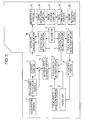
- Fig. 2 is a block diagram showing the function of a digital single-lens reflex camera with an interchangeable lens.
- the camera is an optical apparatus according to a first embodiment of the present invention.
- An acceleration sensor 1 detects the acceleration of the camera in an optical-axis direction.
- a displacement calculation portion 3 calculates the displacement of the blur in the optical-axis direction by applying second-order integration to a signal obtained such that an output of the acceleration sensor 1 is subtracted by a direct-current (DC) component (i.e., electrical DC offset and DC component caused by acceleration due to gravity).
- DC direct-current
- a release switch 4 can be half pressed (SW1) or fully pressed (SW2).
- a shutter speed setting portion 5 sets the shutter speed when the release switch 4 is half pressed (SW1).
- An aperture stop setting portion 6 sets the aperture value.
- a focal position detection portion 7 detects a focused position of an object.
- An autofocus (AF) control portion 8 controls an AF operation.
- a focus unit 9 includes a focus lens and a motor, and serves as an autofocus unit.
- a focal length detection portion 10 detects a current focal length on the basis of the position of a zoom lens.
- a storage portion 11 stores an output of the displacement calculation portion 3 in the in-focus state.
- a focus-range setting portion 12 sets a focus range within which an object is assumed to be in an in-focus state even if the camera is moved in the optical-axis direction due to hand shake. The range can be set on the basis of the focal length, an object distance obtained on the basis of the position of the focus lens in the in-focus state, and the aperture value set with the aperture stop setting portion 6.
- An in-focus state judgment portion 13 judges whether the displacement obtained such that the output of the displacement calculation portion 3 is subtracted by an output of the storage portion 11, is within the focus range set with the focus-range setting portion 12.
- An exposure control portion 14 allows an exposure to be performed during a period that an object is judged with the in-focus state judgment portion 13 as in an in-focus state when the release switch 4 is fully pressed (SW2).
- SW2 fully pressed
- the exposure control portion 14 stops or completes the exposure.
- An image pickup portion 15 converts the image signal into an electric signal
- a signal processing portion 16 acquires the converted image signal as electronic data
- an image storage portion 17 temporarily stores the electronic data, in accordance with a control signal of the exposure control portion 14.
- An image combination portion 19 in a case where the image storage portion 17 temporarily stores a plurality of images, combines these images and generates a single output image.
- An image recording portion 20 stores the image generated with the image combination portion 19 or an image stored in the image storage portion 17 if a single image is stored, in a nonvolatile storage device.
- Fig. 3 plots time in the x direction and displacement in the optical-axis direction in the y direction. It is assumed that the AF operation of the focus unit 9 is completed at the time indicated by the dotted line in Fig. 3 , and an object is brought into an in-focus state at that point.
- the storage portion 11 stores the displacement in the optical-axis direction in the in-focus state.
- the focus-range setting portion 12 determines a focus range within which an object is assumed to be in an in-focus state on the basis of a currently focused position, in accordance with the object distance, the aperture value determined with the aperture stop setting portion 6, and the current focal length.
- the focus range is similar to the depth of field, however, is not equivalent thereto.
- a time lag or the like for the start or completion of the exposure it is desirable that the focus range is smaller than the depth of field.
- a hysteresis may be applied to a value of displacement at the start or completion of the exposure within the focus range.
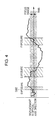
- Fig. 4 is similar to Fig. 3 and plots time in the x direction and displacement in the optical-axis direction in the y direction.
- the displacement in the optical-axis direction is subtracted by the displacement in the in-focus state stored in the storage portion 11, namely by an offset, and the value is displayed.
- a range indicated with an arrow and a name of "focus range” is the focus range set with the focus-range setting portion 12.
- Fig. 5 is an illustration showing an operation of combining images obtained by three exposures as shown in Fig. 4 , and generating a single image.
- the exposure control portion 14 determines the number of exposures. The exposures are performed until the total exposure time reaches a predetermined exposure time set with the shutter speed setting portion 5. However, when the in-focus state judgment portion 13 judges that the unfocused state is continued for a given time or more, a different operation is performed. The details of the operation will be described later.
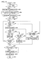
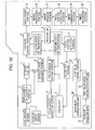
- Fig. 6 is a flowchart showing the operation of this embodiment.
- the focal position detection portion 7 detects the focal point.
- the AF control portion 8 drives an AF motor disposed in the focus unit 9, so that the lens is stopped at a target focus position. Then, the focal position detection portion 7 detects a focal point again.
- the AF processing is completed (S003).
- the storage portion 11 stores an output of the displacement calculation portion 3 at the completion of the AF processing (S004). Also, the focus-range setting portion 12 determines the focus range within which an object is assumed to be in an in-focus state, on the basis of the object distance, focal length and aperture value, which are optical information at the completion of the AF processing (S005).
- the in-focus state judgment portion 13 judges whether the object is currently in the in-focus state (S007). The judgment is made because the object may be in an unfocused state when the camera is moved in the optical-axis direction due to hand shake occurring in a period after the AF processing is completed until the operation of SW2, even if the object has been focused by the AF processing.
- the object is in the unfocused state, it is judged whether the unfocused state has been continued for a given time or more (S014). If the unfocused state has not been continued for the given time or more, the processing returns to step S007 and the judgment is made again. If the unfocused sate has been continued for the given time or more, the processing goes to unfocused state processing. The details of the processing will be described later.
- step S007 If it is judged that the object is in the in-focus state in step S007, a mirror is moved up and a shutter is opened to start an exposure (S008).
- the in-focus state judgment portion 13 judges whether the object is in the in-focus state during the exposure (S009). If the in-focus state is continued, it is judged whether the exposure time has reached the predetermined exposure time set with the shutter speed setting portion 5 (S012). The exposure is continued if the exposure has not yet reached the predetermined exposure time, whereas the mirror is moved down and the shutter is closed to complete the exposure if the exposure has been continued for the predetermined exposure time (S013).
- step S009 If it is determined that the object is "out of the focus range" in step S009, the exposure is completed (S010). Then, it is judged whether the exposure time has reached the predetermined exposure time set with the shutter speed setting portion 5 (S011). If the exposure time has not reached the predetermined exposure time, the processing returns to step S007.
- the image storage portion 17 temporarily stores the acquired images.
- step S018 If the image stored in the image storage portion 17 is only a single image, the processing goes to step S018, and the image recording portion 20 stores the image in the nonvolatile storage device.
- step S016 If it is judged that the image stored in the image storage portion 17 is a plurality of images in step S016, the processing goes to step S017, and the image combination portion 19 combines the images.
- Each of the plurality of images is an image with an underexposure. Combining the plurality of images can generate an image with an optimum exposure.
- the image recording portion 20 stores the image generated in step S017 in the nonvolatile storage device (S018). After the processing of step S018 is finished, the image temporarily stored in the image storage portion 17 is deleted.
- Figs. 7 to 9 are flowcharts showing unfocused state processing.
- unfocused state processing in one of Figs. 7 to 9 is performed.
- unfocused state processing 1 illustrated by the flowchart in Fig. 7 if the unfocused state has been continued for the given time or more, the focus lens is driven in a direction corresponding to the output of the displacement calculation portion 3, and starts an exposure at the time when the object is in the in-focus state.
- the processing is described in time series.
- step S104 it is judged whether the image storage portion 17 has temporarily stored the image during a period between the operation of SW2 and the beginning of the processing (5102). If no image has been temporarily stored, the processing goes to step S104.
- step S104 If an image has been temporarily stored, the temporarily stored image in the image storage portion 17 is deleted (S103), and the processing goes to step S104.
- step S104 the focus lens is driven by an amount corresponding to a lens driving amount calculated on the basis of the output of the displacement calculation portion 3.
- the output of the displacement calculation portion 3 represents a shift between the position of the camera focused with the operation of SW1 and the current position.
- the driving amount of the focus lens to be moved can be calculated using the output of the displacement calculation portion 3, so that the object is again in the in-focus state.
- step S104 the storage portion 11 stores the output of the displacement calculation portion 3 at the time when driving of the lens is completed (S105). Also, the focus-range setting portion 12 determines the focus range within which the object is assumed to be in the in-focus state, on the basis of the object distance, focal length and aperture value, which are optical information at this time (S106).
- the focus-range setting portion 12 determines the focus range within which the object is assumed to be in the in-focus state on the basis of the three pieces of optical information of the object distance, focal length and aperture value in this embodiment, the focus-range setting portion 12 can determine the focus range within which the object is assumed to be in the in-focus state on the basis of other pieces of information such as an angle of field.
- the object is in an in-focus state, and hence, an exposure is started (S107).
- the in-focus state judgment portion 13 continues to determine the existence of the in-focus state during the exposure (S108). If the in-focus state continues, it is determined whether the exposure time has reached the predetermined exposure time set with the shutter speed setting portion 5 (S111). The exposure is continued if the exposure has not been continued for the predetermined exposure time, whereas the exposure is completed if the exposure has been continued for the predetermined exposure time (S112). After the exposure is completed, the processing returns to step S106, and it is judged whether a plurality of images has been acquired with the single operation of SW2.
- the exposure is completed if it is determined that the object is out of the focus range in step S108 (S109), and it is judged whether the exposure time has reached the predetermined exposure time set with the shutter speed setting portion 5 (S110). If the exposure time has reached the predetermined exposure time, the processing goes to step S114, and the judgment for the in-focus state is performed. If the object is within the focus range again, the exposure is started again (S107).
- the processing returns to step S114, and the judgment for the in-focus state is performed. If the unfocused sate has not been continued for the given time, the unfocused state processing 2 or 3 is performed (S116).
- the given time may be equivalent to the time used in step S104 in Fig. 6 , or may be a different time.
- the sensitivity (ISO speed rate) of the acquired image is increased to compensate for underexposure of the image.
- the unfocused state processing 2 it is judged whether the image storage portion 17 has temporarily stored the image during a period between the ON operation of SW2 and the beginning of the processing (S202). If an image has been temporarily stored, the processing goes to step S203. If no image has been temporarily stored, the unfocused state processing 1 or 3 is performed.
- step S203 if only a single image has been stored in the image storage portion 17, the sensitivity of the image is adjusted to have an optimum brightness. If a plurality of images have been stored, the images are combined into a single image, and then the sensitivity of the image is adjusted to have an optimum brightness.
- an exposure is started immediately when the unfocused state has been continued for a given time or more, and is continued until the exposure time reaches a predetermined exposure time.
- an exposure is immediately started (S302), is continued until the exposure time reaches a predetermined exposure time set with the shutter speed setting portion 5 (S303), and when the exposure time reaches the predetermined exposure time, the exposure is completed (S304).
- an image in focus can be obtained even if a blur in the optical-axis direction seriously affects the image captured.
- the unfocused state processing 3 performs exposure even in the unfocused state. Hence, an image, though having a blur, can be captured.
- the unfocused state processing 3 prevents unavailability of an image in an in-focus state from being continued.
- an underexposure can be compensated by combining images if necessary.
- a highly accurate mechanism for correcting a focus blur is not necessary, and hence, the camera can be prevented from being increased in size and cost, and from having a complicated structure.
- a blur in a direction orthogonal to the optical axis can be reliably corrected by utilizing both optical image-stabilization and electronic image-stabilization.
- the acceleration sensor is used for detection of a focus blur.
- a blur correction function is arranged for correcting a blur in the direction orthogonal to the optical axis.
- an acceleration sensor and an angular speed sensor are used for detection of a focus blur.
- a motion blur optical correction unit and a motion blur electronic correction unit are arranged for correcting a blur in the direction orthogonal to the optical axis.
- the second embodiment is described with reference to Figs. 10 to 13 .
- Like numerals refer like components as in the first embodiment. Also, descriptions of operations similar to those of the first embodiment are omitted. Operations unique to the second embodiment are mainly described.
- Fig. 10 is a block diagram showing the function of a digital single-lens reflex camera with an interchangeable lens, the camera which is an optical apparatus according to the second embodiment of the present invention.
- An acceleration sensor 1 and an angular speed sensor 2 detect an acceleration and an angular speed of a blur in the optical-axis direction.
- the displacement calculation portion 3 obtains a displacement of a blur in the optical-axis direction on the basis of outputs of the acceleration sensor 1 and angular speed sensor 2.
- Fig. 11 is a block diagram showing a way to obtain the displacement.
- the output of the acceleration sensor 1 is passed through a high pass filter 101, so as to eliminate an electrical DC component and a steady acceleration component of gravity.
- the output of the angular speed sensor 2 is applied to an integrator 102, and a slight displacement in a direction of the acceleration of gravity is obtained using the output integrated value.
- a multiplier 104 multiplies the displacement by a predetermined value (K), and a subtracter 103 subtracts the acceleration after passing through the high pass filter 101 by the multiplied value. In this way, an acceleration from which the acceleration component of gravity was completely eliminated can be obtained.
- integrators 105 and 106 apply second-order integration to the obtained acceleration, to obtain a displacement 107 of a blur in the optical-axis direction.
- an angular speed sensor 21 detects an angular speed in the direction orthogonal to the optical axis, in a pitch direction, and in a yaw direction.
- a shift blur angle calculation portion 22 eliminates a DC component from an output of the angular speed sensor 21, and integrates the output, to calculate an angle of a blur in the direction orthogonal to the optical axis.
- a shift blur control portion 23 outputs a driving signal to a shift blur correction unit 24 corresponding to a signal from the shift blur angle calculation portion 22.
- the shift blur correction unit 24 drives a correction lens corresponding to the driving signal from a shift blur control portion 23, to correct an angular blur in the direction orthogonal to the optical-axis direction.
- An image position correction portion 18 corrects positional shifts among images if the image temporarily stored in the image storage portion 17 is a plurality of images.
- Fig. 12 schematically illustrates image combining. It is assumed that three images (a), (b), and (c) are obtained with the operation of SW2.
- the camera of the second embodiment has the motion blur optical correction unit configured to correct an angular blur in the direction orthogonal to the optical axis. However, an angular blur may be still remained because it is not sufficiently corrected, or the position of an object may be slightly shifted in the images because of a shift blur. If these images are simply combined, the combined object image may blur as shown in part (d) of Fig. 12 . To avoid this, the image position correction portion 18 corrects the positional shifts among the plurality of images. With this correction, a combined image with minimized blur can be obtained as shown in part (e) of Fig. 12 .
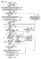
- Fig. 13 is a flowchart showing an operation of the second embodiment. Steps similar to those of the flowchart in Fig. 6 showing the operation of the first embodiment refer step numbers similar thereto.
- the AF motor drives the focus lens, and the lens is stopped at a target position so that the object is in the in-focus state.
- the focal position detection portion 7 detects a focal point again, and if the focal point is in the in-focus state, the AF processing is completed (S003).
- an image-capturing magnification is obtained on the basis of the position of the focus lens determined by the AF processing, and it is judged whether current image-capturing is macro image-capture or not, on the basis of the obtained image-capturing magnification (S021).
- the image recording portion 20 stores the captured image in the nonvolatile storage device (S018).
- the storage portion 11 stores an output of the displacement calculation portion 3 at the completion of the AF processing (S004).
- the focus-range setting portion 12 determines the focus range within which the object is assumed to be in the in-focus state, on the basis of the object distance, focal length and aperture value, which are optical information at the completion of the AF processing (S005).
- the in-focus state judgment portion 13 judges whether an object is currently in the in-focus state (S007).
- step S007 If it is judged that the object is in the in-focus state in step S007, an exposure is started (a mirror is moved up and a shutter is opened) (S008).
- the in-focus state judgment portion 13 judges whether the object is in the in-focus state during the exposure (S009). If the in-focus state is continued, it is judged whether the exposure time has reached a predetermined exposure time set with the shutter speed setting portion 5 (S012).
- the exposure is continued if the exposure has not been continued for the exposure time, whereas the exposure is completed (the mirror is moved down and the shutter is closed) if the exposure has been continued for the predetermined exposure time (S013).
- step S009 If it is determined that the object is not within the focus range in step S009, the exposure is completed (the mirror is moved down and the shutter is closed) (S010).
- step S016 If the total counted exposure time reaches the predetermined exposure time set with the shutter speed setting portion 5, or if the unfocused state processing is finished, it is judged in step S016 whether a plurality of images have been acquired by a single operation of SW2.
- the image storage portion 17 temporarily stores the acquired images.
- step S018 If the image stored in the image storage portion 17 is only a single image, the processing goes to step S018, and the image recording portion 20 stores the image in the nonvolatile storage device.
- step S016 If it is judged that the image stored in the image storage portion 17 is a plurality of images in step S016, the processing goes to step S023, and the image position correction portion 18 corrects positional shifts among the images.
- the image combination portion 19 combines the images with the positional shifts corrected (S017).
- the image recording portion 20 stores the image generated in step S017, in the nonvolatile storage device (S018).
- step S018 After the processing of step S018 is completed, the image temporarily stored in the image storage portion 17 is deleted.
- Unfocused state processing is similar to that of the first embodiment, and the description thereof is omitted.
- the mirror may not be moved up and down when the exposure is started and completed.
- the mirror may be moved up in response to the operation of SW2, and the mirror may be moved down when image-capturing is completed.
- a half silvered mirror which does not move may be used.
- the motion blur optical correction unit does not have to be used for correcting the angular blur in the direction orthogonal to the optical axis: the motion blur electronic correction unit may be used by itself.
- the motion blur electronic correction unit does not have to be used for correcting the shift blur.
- the shift blur may be corrected with the motion blur optical correction unit only, as long as the acceleration sensor or the like detects the shift blur.
- the determination of the macro image-capture may not only rely upon the image-capturing magnification during image-capturing.
- a macro mode switch or the like may be provided, so that the user can select the macro mode.
- the unfocused state processing can be possibly performed in five ways as follows. Either one of the five ways can be performed, or an optimum one can be selected depending on an image-capturing condition such as a shutter speed, or an image-capturing mode.
- An embodiment of the present invention can provide an optical apparatus including taking lens unit (9) arranged to have a focus lens, the apparatus comprising:
- the image pickup control unit (14) preferably controls the image pickup element (15) if the judgment result of the in-focus state judgment unit (13) is within the focus range, controls the image pickup element (15), and obtains an image signal within the focus range.
Description
- The present invention relates to a technique of improving deterioration of a captured image caused by hand shake during image captured by an optical apparatus such as a digital camera. In particular, the present invention relates to a technique of reducing image blurring caused, for example, by hand movement in the optical-axis direction during macro image-capturing.
- An optical apparatus such as a camera or an interchangeable lens is often provided with an image stabilizer that improves an image blur caused by hand-induced shake or the like.
- The hand-induced shake is a vibration normally having a frequency ranging from 1 to 10 Hz. The image stabilizer mainly corrects image blurring caused by vibrations having such a frequency. For image stabilization, the vibration of the optical apparatus is detected. Then, a technique like optical image-stabilization or electronic image-stabilization is used. Optical image-stabilization shifts a correction lens in a plane orthogonal to the optical axis in accordance with the detected vibration. The electronic image-stabilization varies an area, from which data is output as an image, from within the total pixel area of the imaging element.
- If the image-capturing magnification is 0.1 or lower, in general, image blurring can be reliably corrected only by correcting an angular blur in a direction in which the image pickup surface tilts. If the image-capturing magnification is higher than 0.1, the effect of blurring in a parallel direction, i.e., in vertical and horizontal directions (hereinafter, referred to as a shift blur), and the effect of blurring in the optical-axis direction (hereinafter, referred to as a focus blur) may increase.
Fig. 1 is a graph showing the effects of the blurs.Fig. 1 plots image-capturing magnification in the x direction and displacement of the image in an image plane due to blurring in the y direction. - To improve (i.e. reduce) the blurs in an optical apparatus having a high image-capturing magnification such as a macro lens, a technique has been proposed that detects a shift blur and a focus blur with an acceleration sensor or the like, and drives and controls a correction system on the basis of the detection output (see
Japanese Patent Laid-Open No. 09-080523 - The above-mentioned electronic image-stabilization is frequently used in apparatus for recording movies, such as a video camera.
- In the field of still images, a technique has been proposed in which a plurality of underexposure images are captured at a shutter speed which is hardly affected by hand shake, positional shifts among the images are then corrected, and the images are combined, so as to reduce the blurring and obtain a still image with an optimum exposure (see
Japanese Patent No. 03110797 - With the above technique, since the positional shifts among the images can be acquired using the captured images, a blur detection element such as a vibrating gyroscope is not necessary. Also, since the correction is performed on the basis of a blur signal from the image pickup surface, the above-mentioned shift blur and angular blur do not have to be considered separately.
- With both techniques described above, the angular blur and shift blur can be reliably corrected.
- However, with the technique of
Japanese Patent Laid-Open No. 09-080523 - First, as the focus lens is moved in the optical-axis direction, the angle of field is changed. This is one of the important factors of the deterioration in images when high magnification image-capture such as macro image-capture is performed. If a lens for correcting the angle of field is additionally provided for preventing the deterioration in images, the correction system may become complicated. Further, an existing focus lens driving system for auto-focusing cannot accurately follow the blur because the driving characteristic of a motor is insufficient and the backlash is large. While the technique of
Japanese Patent No. 03110797
Other known image blur correction means are described inEP 1 607 792 A ,JP 2006/050139 A JP 4181931 A - The present invention can provide an optical apparatus capable of providing an image having reduced focus blurring caused by hand-induced shake without using an auto-focusing device or a mechanical device for accurately following the blur.
- The present invention provides an optical apparatus as specified in claims 1 to 9.
- With this the present invention, a more focused image can be obtained even if a blur in the optical-axis direction seriously affects the image captured.
- Further aspects of the present invention will become apparent from the following description of exemplary embodiments with reference to the attached drawings.
-
Fig. 1 is a graph showing effects of image-capturing magnifications and motion blurs caused by hand shake to an image plane. -
Fig. 2 is a block diagram showing the function of a digital single-lens reflex camera with an interchangeable lens according to a first embodiment of the present invention. -
Fig. 3 is a first graph showing the relationship between blur in an optical-axis direction and exposure according to the first embodiment of the present invention. -
Fig. 4 is a second graph showing the relationship between blur in the optical-axis direction and the exposure according to the first embodiment of the present invention. -
Fig. 5 is an illustration schematically showing image combining according to the first embodiment of the present invention. -
Fig. 6 is a flowchart showing an operation of the first embodiment of the present invention. -
Fig. 7 is a flowchart showing an operation of unfocused state processing 1 according to the first embodiment of the present invention. -
Fig. 8 is a flowchart showing an operation ofunfocused state processing 2 according to the first embodiment of the present invention. -
Fig. 9 is a flowchart showing an operation ofunfocused state processing 3 according to the first embodiment of the present invention. -
Fig. 10 is a block diagram showing the function of a digital single-lens reflex camera with an interchangeable lens according to a second embodiment of the present invention. -
Fig. 11 is a block diagram schematically showing a way to obtain the displacement of a blur in an optical-axis direction according to the second embodiment of the present invention. -
Fig. 12 is an illustration schematically showing image combining according to the second embodiment of the present invention. -
Fig. 13 is a flowchart showing an operation of the second embodiment of the present invention. - Embodiments of the present invention are now described with reference to the attached drawings.
-
Fig. 2 is a block diagram showing the function of a digital single-lens reflex camera with an interchangeable lens. The camera is an optical apparatus according to a first embodiment of the present invention. - An acceleration sensor 1 detects the acceleration of the camera in an optical-axis direction. A
displacement calculation portion 3 calculates the displacement of the blur in the optical-axis direction by applying second-order integration to a signal obtained such that an output of the acceleration sensor 1 is subtracted by a direct-current (DC) component (i.e., electrical DC offset and DC component caused by acceleration due to gravity). - A
release switch 4 can be half pressed (SW1) or fully pressed (SW2). A shutterspeed setting portion 5 sets the shutter speed when therelease switch 4 is half pressed (SW1). An aperturestop setting portion 6 sets the aperture value. - A focal position detection portion 7 detects a focused position of an object. An autofocus (AF) control portion 8 controls an AF operation. A
focus unit 9 includes a focus lens and a motor, and serves as an autofocus unit. - A focal
length detection portion 10 detects a current focal length on the basis of the position of a zoom lens. - A
storage portion 11 stores an output of thedisplacement calculation portion 3 in the in-focus state. A focus-range setting portion 12 sets a focus range within which an object is assumed to be in an in-focus state even if the camera is moved in the optical-axis direction due to hand shake. The range can be set on the basis of the focal length, an object distance obtained on the basis of the position of the focus lens in the in-focus state, and the aperture value set with the aperturestop setting portion 6. An in-focusstate judgment portion 13 judges whether the displacement obtained such that the output of thedisplacement calculation portion 3 is subtracted by an output of thestorage portion 11, is within the focus range set with the focus-range setting portion 12. - An
exposure control portion 14 allows an exposure to be performed during a period that an object is judged with the in-focusstate judgment portion 13 as in an in-focus state when therelease switch 4 is fully pressed (SW2). When the in-focusstate judgment portion 13 judges that the object is in an unfocused state during the exposure, or when the exposure is continued for a predetermined exposure time set with the shutterspeed setting portion 5, theexposure control portion 14 stops or completes the exposure. - An
image pickup portion 15 converts the image signal into an electric signal, asignal processing portion 16 acquires the converted image signal as electronic data, and animage storage portion 17 temporarily stores the electronic data, in accordance with a control signal of theexposure control portion 14. - An
image combination portion 19, in a case where theimage storage portion 17 temporarily stores a plurality of images, combines these images and generates a single output image. - An
image recording portion 20 stores the image generated with theimage combination portion 19 or an image stored in theimage storage portion 17 if a single image is stored, in a nonvolatile storage device. - Next, the relationship between a blur in the optical-axis direction and the exposure is described with reference to
Figs. 3 and4 . -
Fig. 3 plots time in the x direction and displacement in the optical-axis direction in the y direction. It is assumed that the AF operation of thefocus unit 9 is completed at the time indicated by the dotted line inFig. 3 , and an object is brought into an in-focus state at that point. Thestorage portion 11 stores the displacement in the optical-axis direction in the in-focus state. - At the time when the object is brought into the in-focus state, an object distance is determined on the basis of the position of the focus lens. The focus-
range setting portion 12 determines a focus range within which an object is assumed to be in an in-focus state on the basis of a currently focused position, in accordance with the object distance, the aperture value determined with the aperturestop setting portion 6, and the current focal length. The focus range is similar to the depth of field, however, is not equivalent thereto. Regarding a time lag or the like for the start or completion of the exposure, it is desirable that the focus range is smaller than the depth of field. To prevent chattering from occurring during the start or completion of the exposure, a hysteresis may be applied to a value of displacement at the start or completion of the exposure within the focus range. -
Fig. 4 is similar toFig. 3 and plots time in the x direction and displacement in the optical-axis direction in the y direction. The displacement in the optical-axis direction is subtracted by the displacement in the in-focus state stored in thestorage portion 11, namely by an offset, and the value is displayed. InFig. 4 , a range indicated with an arrow and a name of "focus range" is the focus range set with the focus-range setting portion 12. When therelease switch 4 is full pressed (SW2) at the time indicated by the dotted-chain line, the exposure is performed only while the displacement is within the focus range, or only during periods indicated by oblique lines inFig. 4 . -
Fig. 5 is an illustration showing an operation of combining images obtained by three exposures as shown inFig. 4 , and generating a single image. Theexposure control portion 14 determines the number of exposures. The exposures are performed until the total exposure time reaches a predetermined exposure time set with the shutterspeed setting portion 5. However, when the in-focusstate judgment portion 13 judges that the unfocused state is continued for a given time or more, a different operation is performed. The details of the operation will be described later. -
Fig. 6 is a flowchart showing the operation of this embodiment. When a user half presses therelease switch 4 so as to focus on an object (S002), the focal position detection portion 7 detects the focal point. On the basis of the result of the focal point detection, the AF control portion 8 drives an AF motor disposed in thefocus unit 9, so that the lens is stopped at a target focus position. Then, the focal position detection portion 7 detects a focal point again. When it is detected that focal point is in the in-focus state, the AF processing is completed (S003). - Then, the
storage portion 11 stores an output of thedisplacement calculation portion 3 at the completion of the AF processing (S004). Also, the focus-range setting portion 12 determines the focus range within which an object is assumed to be in an in-focus state, on the basis of the object distance, focal length and aperture value, which are optical information at the completion of the AF processing (S005). - When the user fully presses the release switch 4 (S006), the in-focus
state judgment portion 13 judges whether the object is currently in the in-focus state (S007). The judgment is made because the object may be in an unfocused state when the camera is moved in the optical-axis direction due to hand shake occurring in a period after the AF processing is completed until the operation of SW2, even if the object has been focused by the AF processing. - If the object is in the unfocused state, it is judged whether the unfocused state has been continued for a given time or more (S014). If the unfocused state has not been continued for the given time or more, the processing returns to step S007 and the judgment is made again. If the unfocused sate has been continued for the given time or more, the processing goes to unfocused state processing. The details of the processing will be described later.
- If it is judged that the object is in the in-focus state in step S007, a mirror is moved up and a shutter is opened to start an exposure (S008). The in-focus
state judgment portion 13 judges whether the object is in the in-focus state during the exposure (S009). If the in-focus state is continued, it is judged whether the exposure time has reached the predetermined exposure time set with the shutter speed setting portion 5 (S012). The exposure is continued if the exposure has not yet reached the predetermined exposure time, whereas the mirror is moved down and the shutter is closed to complete the exposure if the exposure has been continued for the predetermined exposure time (S013). - If it is determined that the object is "out of the focus range" in step S009, the exposure is completed (S010). Then, it is judged whether the exposure time has reached the predetermined exposure time set with the shutter speed setting portion 5 (S011). If the exposure time has not reached the predetermined exposure time, the processing returns to step S007.
- If the total counted exposure time reaches the predetermined exposure time set with the shutter
speed setting portion 5, or if the unfocused state processing is finished, it is judged whether a plurality of images have been acquired by a single operation of SW2 in step S016. Theimage storage portion 17 temporarily stores the acquired images. - If the image stored in the
image storage portion 17 is only a single image, the processing goes to step S018, and theimage recording portion 20 stores the image in the nonvolatile storage device. - If it is judged that the image stored in the
image storage portion 17 is a plurality of images in step S016, the processing goes to step S017, and theimage combination portion 19 combines the images. Each of the plurality of images is an image with an underexposure. Combining the plurality of images can generate an image with an optimum exposure. Theimage recording portion 20 stores the image generated in step S017 in the nonvolatile storage device (S018). After the processing of step S018 is finished, the image temporarily stored in theimage storage portion 17 is deleted. -
Figs. 7 to 9 are flowcharts showing unfocused state processing. - If it is determined that the unfocused state has been continued for the given time or more in step S014 of
Fig. 6 , unfocused state processing in one ofFigs. 7 to 9 is performed. - In unfocused state processing 1 illustrated by the flowchart in
Fig. 7 , if the unfocused state has been continued for the given time or more, the focus lens is driven in a direction corresponding to the output of thedisplacement calculation portion 3, and starts an exposure at the time when the object is in the in-focus state. Hereinafter, the processing is described in time series. - Once the unfocused state processing 1 is started, it is judged whether the
image storage portion 17 has temporarily stored the image during a period between the operation of SW2 and the beginning of the processing (5102). If no image has been temporarily stored, the processing goes to step S104. - If an image has been temporarily stored, the temporarily stored image in the
image storage portion 17 is deleted (S103), and the processing goes to step S104. - In step S104, the focus lens is driven by an amount corresponding to a lens driving amount calculated on the basis of the output of the
displacement calculation portion 3. The output of thedisplacement calculation portion 3 represents a shift between the position of the camera focused with the operation of SW1 and the current position. - Thus, the driving amount of the focus lens to be moved can be calculated using the output of the
displacement calculation portion 3, so that the object is again in the in-focus state. - In step S104, the
storage portion 11 stores the output of thedisplacement calculation portion 3 at the time when driving of the lens is completed (S105). Also, the focus-range setting portion 12 determines the focus range within which the object is assumed to be in the in-focus state, on the basis of the object distance, focal length and aperture value, which are optical information at this time (S106). - While the focus-
range setting portion 12 determines the focus range within which the object is assumed to be in the in-focus state on the basis of the three pieces of optical information of the object distance, focal length and aperture value in this embodiment, the focus-range setting portion 12 can determine the focus range within which the object is assumed to be in the in-focus state on the basis of other pieces of information such as an angle of field. - At the time when the above step is completed, the object is in an in-focus state, and hence, an exposure is started (S107). The in-focus
state judgment portion 13 continues to determine the existence of the in-focus state during the exposure (S108). If the in-focus state continues, it is determined whether the exposure time has reached the predetermined exposure time set with the shutter speed setting portion 5 (S111). The exposure is continued if the exposure has not been continued for the predetermined exposure time, whereas the exposure is completed if the exposure has been continued for the predetermined exposure time (S112). After the exposure is completed, the processing returns to step S106, and it is judged whether a plurality of images has been acquired with the single operation of SW2. - The exposure is completed if it is determined that the object is out of the focus range in step S108 (S109), and it is judged whether the exposure time has reached the predetermined exposure time set with the shutter speed setting portion 5 (S110). If the exposure time has reached the predetermined exposure time, the processing goes to step S114, and the judgment for the in-focus state is performed. If the object is within the focus range again, the exposure is started again (S107).
- If the object is out of the focus range, it is judged whether the unfocused state has been continued for a given time (S115). If the unfocused state has been continued for the given time, the processing returns to step S114, and the judgment for the in-focus state is performed. If the unfocused sate has not been continued for the given time, the
unfocused state processing Fig. 6 , or may be a different time. - In the
unfocused state processing 2 illustrated with the flowchart inFig. 8 , if the unfocused state has been continued for a given time or more, the sensitivity (ISO speed rate) of the acquired image is increased to compensate for underexposure of the image. - Once the
unfocused state processing 2 is started, it is judged whether theimage storage portion 17 has temporarily stored the image during a period between the ON operation of SW2 and the beginning of the processing (S202). If an image has been temporarily stored, the processing goes to step S203. If no image has been temporarily stored, theunfocused state processing 1 or 3 is performed. - In step S203, if only a single image has been stored in the
image storage portion 17, the sensitivity of the image is adjusted to have an optimum brightness. If a plurality of images have been stored, the images are combined into a single image, and then the sensitivity of the image is adjusted to have an optimum brightness. - In the
unfocused state processing 3 illustrated with the flowchart inFig. 9 , an exposure is started immediately when the unfocused state has been continued for a given time or more, and is continued until the exposure time reaches a predetermined exposure time. - Once the
unfocused state processing 3 is started, an exposure is immediately started (S302), is continued until the exposure time reaches a predetermined exposure time set with the shutter speed setting portion 5 (S303), and when the exposure time reaches the predetermined exposure time, the exposure is completed (S304). - With this embodiment, an image in focus can be obtained even if a blur in the optical-axis direction seriously affects the image captured.
- If the in-focus state has not been continued for a given time, the
unfocused state processing 3 performs exposure even in the unfocused state. Hence, an image, though having a blur, can be captured. Theunfocused state processing 3 prevents unavailability of an image in an in-focus state from being continued. - Also, an underexposure can be compensated by combining images if necessary. A highly accurate mechanism for correcting a focus blur is not necessary, and hence, the camera can be prevented from being increased in size and cost, and from having a complicated structure.
- Further, a blur in a direction orthogonal to the optical axis can be reliably corrected by utilizing both optical image-stabilization and electronic image-stabilization.
- In the above-described first embodiment, the acceleration sensor is used for detection of a focus blur. Also, a blur correction function is arranged for correcting a blur in the direction orthogonal to the optical axis.
- In a second embodiment, an acceleration sensor and an angular speed sensor are used for detection of a focus blur. Also, a motion blur optical correction unit and a motion blur electronic correction unit are arranged for correcting a blur in the direction orthogonal to the optical axis.
- The second embodiment is described with reference to
Figs. 10 to 13 . Like numerals refer like components as in the first embodiment. Also, descriptions of operations similar to those of the first embodiment are omitted. Operations unique to the second embodiment are mainly described. -
Fig. 10 is a block diagram showing the function of a digital single-lens reflex camera with an interchangeable lens, the camera which is an optical apparatus according to the second embodiment of the present invention. - An acceleration sensor 1 and an
angular speed sensor 2 detect an acceleration and an angular speed of a blur in the optical-axis direction. Thedisplacement calculation portion 3 obtains a displacement of a blur in the optical-axis direction on the basis of outputs of the acceleration sensor 1 andangular speed sensor 2. -
Fig. 11 is a block diagram showing a way to obtain the displacement. The output of the acceleration sensor 1 is passed through ahigh pass filter 101, so as to eliminate an electrical DC component and a steady acceleration component of gravity. - The output of the
angular speed sensor 2 is applied to anintegrator 102, and a slight displacement in a direction of the acceleration of gravity is obtained using the output integrated value. Amultiplier 104 multiplies the displacement by a predetermined value (K), and asubtracter 103 subtracts the acceleration after passing through thehigh pass filter 101 by the multiplied value. In this way, an acceleration from which the acceleration component of gravity was completely eliminated can be obtained. Then,integrators displacement 107 of a blur in the optical-axis direction. - Referring back to
Fig. 10 , anangular speed sensor 21 detects an angular speed in the direction orthogonal to the optical axis, in a pitch direction, and in a yaw direction. A shift blurangle calculation portion 22 eliminates a DC component from an output of theangular speed sensor 21, and integrates the output, to calculate an angle of a blur in the direction orthogonal to the optical axis. - A shift
blur control portion 23 outputs a driving signal to a shiftblur correction unit 24 corresponding to a signal from the shift blurangle calculation portion 22. The shiftblur correction unit 24 drives a correction lens corresponding to the driving signal from a shiftblur control portion 23, to correct an angular blur in the direction orthogonal to the optical-axis direction. - An image
position correction portion 18 corrects positional shifts among images if the image temporarily stored in theimage storage portion 17 is a plurality of images. -
Fig. 12 schematically illustrates image combining. It is assumed that three images (a), (b), and (c) are obtained with the operation of SW2. As described above, the camera of the second embodiment has the motion blur optical correction unit configured to correct an angular blur in the direction orthogonal to the optical axis. However, an angular blur may be still remained because it is not sufficiently corrected, or the position of an object may be slightly shifted in the images because of a shift blur. If these images are simply combined, the combined object image may blur as shown in part (d) ofFig. 12 . To avoid this, the imageposition correction portion 18 corrects the positional shifts among the plurality of images. With this correction, a combined image with minimized blur can be obtained as shown in part (e) ofFig. 12 .Fig. 13 is a flowchart showing an operation of the second embodiment. Steps similar to those of the flowchart inFig. 6 showing the operation of the first embodiment refer step numbers similar thereto. - When a user half presses the release switch 4 (S002), correction of a shift blur is started (S020). The focal position detection portion 7 detects a focal point, and the AF control portion 8 drives the AF motor disposed in the
focus unit 9 accordingly. - The AF motor drives the focus lens, and the lens is stopped at a target position so that the object is in the in-focus state.
- The focal position detection portion 7 detects a focal point again, and if the focal point is in the in-focus state, the AF processing is completed (S003).
- Then, an image-capturing magnification is obtained on the basis of the position of the focus lens determined by the AF processing, and it is judged whether current image-capturing is macro image-capture or not, on the basis of the obtained image-capturing magnification (S021).
- If the macro image-capturing is not performed, normal image-capturing is performed which is not particularly described in this specification (5022). The
image recording portion 20 stores the captured image in the nonvolatile storage device (S018). - If it is judged that macro image-capture is performed in step S021, the
storage portion 11 stores an output of thedisplacement calculation portion 3 at the completion of the AF processing (S004). - Also, the focus-
range setting portion 12 determines the focus range within which the object is assumed to be in the in-focus state, on the basis of the object distance, focal length and aperture value, which are optical information at the completion of the AF processing (S005). - When the user fully presses the release switch 4 (S006), the in-focus
state judgment portion 13 judges whether an object is currently in the in-focus state (S007). - If the object is not judged as in the in-focus state, it is judged whether the unfocused state has been continued for a given time or more (S014). If the unfocused state has not been continued for the given time or more, the processing returns to the step S007 and the judgment is made again.
- If the unfocused state has been continued for the given time or more, the processing goes to unfocused state processing.
- If it is judged that the object is in the in-focus state in step S007, an exposure is started (a mirror is moved up and a shutter is opened) (S008).
- The in-focus
state judgment portion 13 judges whether the object is in the in-focus state during the exposure (S009). If the in-focus state is continued, it is judged whether the exposure time has reached a predetermined exposure time set with the shutter speed setting portion 5 (S012). - The exposure is continued if the exposure has not been continued for the exposure time, whereas the exposure is completed (the mirror is moved down and the shutter is closed) if the exposure has been continued for the predetermined exposure time (S013).
- If it is determined that the object is not within the focus range in step S009, the exposure is completed (the mirror is moved down and the shutter is closed) (S010).
- Then, it is judged whether the exposure time has reached the predetermined exposure time set with the shutter speed setting portion 5 (S011).
- If the exposure time has not reached the predetermined exposure time, the processing returns to step S007.
- If the total counted exposure time reaches the predetermined exposure time set with the shutter
speed setting portion 5, or if the unfocused state processing is finished, it is judged in step S016 whether a plurality of images have been acquired by a single operation of SW2. - The
image storage portion 17 temporarily stores the acquired images. - If the image stored in the
image storage portion 17 is only a single image, the processing goes to step S018, and theimage recording portion 20 stores the image in the nonvolatile storage device. - If it is judged that the image stored in the
image storage portion 17 is a plurality of images in step S016, the processing goes to step S023, and the imageposition correction portion 18 corrects positional shifts among the images. - Then, the
image combination portion 19 combines the images with the positional shifts corrected (S017). - The
image recording portion 20 stores the image generated in step S017, in the nonvolatile storage device (S018). - After the processing of step S018 is completed, the image temporarily stored in the
image storage portion 17 is deleted. - Unfocused state processing is similar to that of the first embodiment, and the description thereof is omitted.
- The embodiments of the present invention are described above, however, the present invention is not limited thereto and various modifications can be made.
- For example, the mirror may not be moved up and down when the exposure is started and completed. The mirror may be moved up in response to the operation of SW2, and the mirror may be moved down when image-capturing is completed. As an alternative a half silvered mirror which does not move may be used.
- The motion blur optical correction unit does not have to be used for correcting the angular blur in the direction orthogonal to the optical axis: the motion blur electronic correction unit may be used by itself.
- The motion blur electronic correction unit does not have to be used for correcting the shift blur. The shift blur may be corrected with the motion blur optical correction unit only, as long as the acceleration sensor or the like detects the shift blur.
- The determination of the macro image-capture may not only rely upon the image-capturing magnification during image-capturing. A macro mode switch or the like may be provided, so that the user can select the macro mode.
- The unfocused state processing can be possibly performed in five ways as follows. Either one of the five ways can be performed, or an optimum one can be selected depending on an image-capturing condition such as a shutter speed, or an image-capturing mode.
- 1) Perform the unfocused state processing 1, the
unfocused state processing 2, and theunfocused state processing 3 in sequence. - 2) Perform the
unfocused state processing 2, the unfocused state processing 1, and theunfocused state processing 3 in sequence. - 3) Perform the unfocused state processing 1 and the
unfocused state processing 3 in sequence. - 4) Perform the
unfocused state processing 2 and theunfocused state processing 3 in sequence. - 5) Perform only the
unfocused state processing 3. - While the present invention has been described with reference to exemplary embodiments, it is to be understood that the invention is not limited to the disclosed exemplary embodiments. The scope of the following claims is to be accorded the broadest interpretation so as to encompass all modifications, equivalent structures and functions.
- An embodiment of the present invention can provide an optical apparatus including taking lens unit (9) arranged to have a focus lens, the apparatus comprising:
- an image pickup element (15) including an image pickup element, the image pickup element being arranged to pick up an object image focused on the image pickup element and convert the object image into an image signal;
- an autofocus unit (8) configured to drive the focus lens to bring the object image on the image pickup element into an in-focus state;
- an image pickup control unit (14) configured to start image-capturing an object in response to an operation of an image pickup start switch, and to perform control for obtaining the image signal from the image pickup element (15);
- a displacement detection unit (3) arranged to output a displacement signal of the optical apparatus in an optical-axis direction;
- a memory (11) arranged to store an output of the displacement detection unit (3) when the object image is brought into the in-focus state with the autofocus unit (8) ;
- a focus-range setting unit (12) configured to set a focus range within which the object image is assumed to be in-focus accordance with a condition of the taking lens unit (9), even if the optical apparatus is displaced in the optical-axis direction; and
- an in-focus state judgment unit (13) configured to judge whether the detected displacement is within the set focus range,
- The image pickup control unit (14) preferably controls the image pickup element (15) if the judgment result of the in-focus state judgment unit (13) is within the focus range, controls the image pickup element (15), and obtains an image signal within the focus range.
Claims (8)
- An optical apparatus including a lens system (9) having a focus lens and an image pickup element (15) for converting an image formed by the lens system into an image signal, the apparatus including:control means (14) configured to control operation of the apparatus;auto-focus means (8) configured to move the focus lens to bring the image into an in-focus state;displacement detection means (3) configured to detect a displacement of the optical apparatus in the direction of the optical axis of the lens system;characterized in that the optical apparatus further comprises:focus-range setting means (12, 13) configured to calculate an acceptable range of detected displacement within which it is assumed that the image remains in an in-focus state;image pickup time setting means (5) operable to set a predetermined total image pickup time corresponding to one or more parameters relating to image capturing conditions selected from the group consisting of: aperture size, focal length, and the distance to the object to be captured; andimage combination means (19) configured to combine a plurality of image signals obtained with the image pickup element (15),wherein when the detected displacement is within the acceptable range, the image pickup element (15) is operable to pick up a plurality of object image signals until a total image pickup time controlled with the control means (14) reaches the predetermined total image pickup time set with the image pickup time setting means (5), and the image combination means (19) is operable to combine said plurality of object image signals obtained with the image pickup element (15) and to generate a single image, and wherein the control means is operable, when the detected displacement is outside the acceptable range, to stop or complete exposure such that exposure for the plurality of image signals is only performed when the detected displacement is within said acceptable range.
- The optical apparatus according to claim 1, wherein the focus range setting means is operable to calculate an acceptable range of detected displacement based on one or more of the parameters: aperture size, focal length, and the distance to the object to be captured.
- The optical apparatus according to any preceding claim, further comprising:acceleration detection means (1) configured to detect an acceleration of the optical apparatus in the optical-axis direction,wherein the displacement detection means (3) is operable to obtain the displacement of the optical apparatus in the optical-axis direction by applying a calculation to an output signal of the acceleration detection means (1).
- The optical apparatus according to claim 3,
wherein the acceleration detection means (1) is operable to detect the acceleration and angular speed of the optical apparatus, and the displacement detection means is operable to detect the displacement in the optical-axis direction based on the detected acceleration and/or angular speed. - The optical apparatus according to claim 2, further comprising:image position correction means (18) configured to correct positional shifts among the plurality of images before the plurality of images are combined.
- The optical apparatus according to any preceding claim,
wherein the control means (14) is operable, if the output of the displacement detection means (3) is not within the acceptable range for a predetermined time after an image pickup start switch is operated, to cause the focus lens to be driven to a position where the focus lens is focused on the object on the basis of the output of the displacement detection means (3). - The optical apparatus according to any one of claims 1 to 5,
wherein the control means (14) is operable, if the output of the displacement detection means (3) is not within the acceptable range for a predetermined time and if the image pickup element (15) has acquired at least one image after an image pickup start switch is operated, to cause the sensitivity of the apparatus to be increased to compensate for under exposure and
to obtain an image having an optimum brightness. - The optical apparatus according to any one of claims 1 to 5,
wherein the control means (14) is operable, if the output of the displacement detection means (3) is out of the acceptable range for a predetermined time after an image pickup start switch is operated, to cause the image pickup element (15) to start picking up an image, and to continue an exposure until the elapsed image pickup time reaches a predetermined total image pickup time set by the image pickup time setting means (5).
Applications Claiming Priority (1)
| Application Number | Priority Date | Filing Date | Title |
|---|---|---|---|
| JP2006343430A JP4757185B2 (en) | 2006-12-20 | 2006-12-20 | Optical equipment |
Publications (2)
| Publication Number | Publication Date |
|---|---|
| EP1936435A1 EP1936435A1 (en) | 2008-06-25 |
| EP1936435B1 true EP1936435B1 (en) | 2011-03-23 |
Family
ID=39167414
Family Applications (1)
| Application Number | Title | Priority Date | Filing Date |
|---|---|---|---|
| EP07123874A Expired - Fee Related EP1936435B1 (en) | 2006-12-20 | 2007-12-20 | Optical apparatus with unit for correcting blur of captured image caused by displacement of optical apparatus in optical-axis direction |
Country Status (4)
| Country | Link |
|---|---|
| US (2) | US7907205B2 (en) |
| EP (1) | EP1936435B1 (en) |
| JP (1) | JP4757185B2 (en) |
| DE (1) | DE602007013347D1 (en) |
Families Citing this family (15)
| Publication number | Priority date | Publication date | Assignee | Title |
|---|---|---|---|---|
| JP4552974B2 (en) * | 2007-06-22 | 2010-09-29 | カシオ計算機株式会社 | Camera device, focus control method and program |
| JP4488041B2 (en) * | 2007-08-02 | 2010-06-23 | ソニー株式会社 | Image blur correction apparatus and imaging apparatus |
| JP5072764B2 (en) * | 2008-08-01 | 2012-11-14 | キヤノン株式会社 | Optical apparatus and camera system |
| JP5230505B2 (en) * | 2009-03-30 | 2013-07-10 | キヤノン株式会社 | Imaging device |
| JP5383280B2 (en) * | 2009-03-30 | 2014-01-08 | キヤノン株式会社 | IMAGING DEVICE, OPTICAL DEVICE, AND METHOD FOR CONTROLLING IMAGING DEVICE |
| US8743309B2 (en) * | 2009-11-10 | 2014-06-03 | Apple Inc. | Methods for fabricating display structures |
| KR101605129B1 (en) * | 2009-11-26 | 2016-03-21 | 삼성전자주식회사 | Digital photographing apparatus, controlling method thereof and recording medium for the same |
| US8798388B2 (en) * | 2009-12-03 | 2014-08-05 | Qualcomm Incorporated | Digital image combining to produce optical effects |
| JP5528139B2 (en) | 2010-02-02 | 2014-06-25 | キヤノン株式会社 | Image processing apparatus, imaging apparatus, and image processing program |
| JP2014126861A (en) | 2012-12-27 | 2014-07-07 | Canon Inc | Imaging device and control method of the same, program and storage medium |
| JP6071545B2 (en) * | 2012-12-27 | 2017-02-01 | キヤノン株式会社 | IMAGING DEVICE, IMAGE PROCESSING DEVICE AND ITS CONTROL METHOD, PROGRAM, AND STORAGE MEDIUM |
| JP6017381B2 (en) * | 2013-07-22 | 2016-11-02 | オリンパス株式会社 | Image blur correction apparatus and imaging apparatus |
| US10419658B1 (en) | 2014-07-20 | 2019-09-17 | Promanthan Brains LLC, Series Point only | Camera optimizing for several directions of interest |
| JP7208822B2 (en) * | 2019-02-22 | 2023-01-19 | キヤノン株式会社 | IMAGING DEVICE AND CONTROL METHOD THEREOF, PROGRAM, STORAGE MEDIUM |
| CN113347335B (en) * | 2021-05-31 | 2022-08-30 | 浙江大华技术股份有限公司 | Focusing method, device, electronic equipment and storage medium |
Family Cites Families (19)
| Publication number | Priority date | Publication date | Assignee | Title |
|---|---|---|---|---|
| JP2961761B2 (en) * | 1989-09-14 | 1999-10-12 | ミノルタ株式会社 | Optical device |
| US5109249A (en) | 1989-10-12 | 1992-04-28 | Ricoh Company, Ltd. | Camera with a function of preventing a hand moving blur |
| JP2897414B2 (en) | 1990-11-16 | 1999-05-31 | ミノルタ株式会社 | Camera with blur prevention function |
| JP3110797B2 (en) | 1991-06-21 | 2000-11-20 | キヤノン株式会社 | Imaging method and imaging screen synthesis device |
| JP3513950B2 (en) * | 1993-12-14 | 2004-03-31 | 株式会社ニコン | Image stabilization camera |
| US5794078A (en) | 1995-09-11 | 1998-08-11 | Nikon Corporation | Image movement correction of camera |
| JPH0980523A (en) * | 1995-09-11 | 1997-03-28 | Nikon Corp | Image blurring correction camera |
| JP4013283B2 (en) * | 1997-05-12 | 2007-11-28 | 株式会社ニコン | Camera with autofocus function |
| JP4063924B2 (en) * | 1997-09-02 | 2008-03-19 | オリンパス株式会社 | Camera autofocus device |
| JP2002139761A (en) | 2000-11-02 | 2002-05-17 | Olympus Optical Co Ltd | Camera having shake notifying function |
| JP2003140025A (en) * | 2001-11-01 | 2003-05-14 | Olympus Optical Co Ltd | Image pickup device |
| JP2005244725A (en) * | 2004-02-27 | 2005-09-08 | Pentax Corp | Image blur correction apparatus |
| WO2005093654A2 (en) | 2004-03-25 | 2005-10-06 | Fatih Ozluturk | Method and apparatus to correct digital image blur due to motion of subject or imaging device |
| JP4717382B2 (en) | 2004-06-15 | 2011-07-06 | キヤノン株式会社 | Optical equipment |
| JP2006050139A (en) * | 2004-08-03 | 2006-02-16 | Canon Inc | Optical apparatus |
| JP2006054698A (en) * | 2004-08-12 | 2006-02-23 | Canon Inc | Imaging apparatus having camera shake correction function |
| JP4311668B2 (en) * | 2004-11-15 | 2009-08-12 | オリンパス株式会社 | Imaging apparatus, imaging system, and image capturing method |
| JP4667052B2 (en) * | 2005-01-27 | 2011-04-06 | キヤノン株式会社 | Imaging device, camera body and interchangeable lens thereof |
| JP2007020109A (en) | 2005-07-11 | 2007-01-25 | Olympus Imaging Corp | Electronic blur correction apparatus |
-
2006
- 2006-12-20 JP JP2006343430A patent/JP4757185B2/en not_active Expired - Fee Related
-
2007
- 2007-12-14 US US11/957,263 patent/US7907205B2/en not_active Expired - Fee Related
- 2007-12-20 DE DE602007013347T patent/DE602007013347D1/en active Active
- 2007-12-20 EP EP07123874A patent/EP1936435B1/en not_active Expired - Fee Related
-
2010
- 2010-08-12 US US12/855,594 patent/US8456566B2/en not_active Expired - Fee Related
Also Published As
| Publication number | Publication date |
|---|---|
| EP1936435A1 (en) | 2008-06-25 |
| US20100302387A1 (en) | 2010-12-02 |
| JP4757185B2 (en) | 2011-08-24 |
| DE602007013347D1 (en) | 2011-05-05 |
| US8456566B2 (en) | 2013-06-04 |
| US20080151096A1 (en) | 2008-06-26 |
| JP2008160208A (en) | 2008-07-10 |
| US7907205B2 (en) | 2011-03-15 |
Similar Documents
| Publication | Publication Date | Title |
|---|---|---|
| EP1936435B1 (en) | Optical apparatus with unit for correcting blur of captured image caused by displacement of optical apparatus in optical-axis direction | |
| JP5013078B2 (en) | Lens barrel and imaging device | |
| WO2011048752A1 (en) | Focusing system, interchangeable lens, and image-capturing device | |
| KR101575626B1 (en) | Digital camera and controlling method thereof | |
| JP6749791B2 (en) | Imaging device and automatic focusing method | |
| US7557831B2 (en) | Optical apparatus provided with image-shake correction function | |
| JP5932410B2 (en) | Imaging device | |
| JP6642971B2 (en) | Image blur correction device, optical device, imaging device, and control method | |
| JP5932226B2 (en) | Imaging device | |
| JP2009267681A (en) | Blur corrector and optical device | |
| JP2012159796A (en) | Focus adjustment device and imaging apparatus | |
| JP2010145493A (en) | Camera system | |
| JP2010026172A (en) | Lens barrel, method of adjusting lens barrel, optical device, and method of adjusting optical device | |
| JP4845653B2 (en) | Camera system, camera body, interchangeable lens unit, and image blur correction method | |
| JP6627208B2 (en) | Imaging device | |
| JP7166949B2 (en) | CONTROL DEVICE, AND LENS DEVICE AND IMAGING DEVICE INCLUDING THE SAME | |
| JP2014092756A (en) | Image shake correcting device, optical equipment comprising the same, imaging device, and control method of image shake correcting device | |
| JP2006171654A (en) | Photographic apparatus | |
| JP5541661B2 (en) | LENS DEVICE, IMAGING SYSTEM, AND CONTROL METHOD THEREOF | |
| JP2010145500A (en) | Optical equipment | |
| JP2009175241A (en) | Optical apparatus and adjusting method thereof | |
| WO2020013200A1 (en) | Replacement lens and camera body | |
| JP2009171324A (en) | Photographing apparatus | |
| JP2009015184A (en) | Imaging device | |
| WO2019203147A1 (en) | Imaging device |
Legal Events
| Date | Code | Title | Description |
|---|---|---|---|
| PUAI | Public reference made under article 153(3) epc to a published international application that has entered the european phase |
Free format text: ORIGINAL CODE: 0009012 |
|
| AK | Designated contracting states |
Kind code of ref document: A1 Designated state(s): AT BE BG CH CY CZ DE DK EE ES FI FR GB GR HU IE IS IT LI LT LU LV MC MT NL PL PT RO SE SI SK TR |
|
| AX | Request for extension of the european patent |
Extension state: AL BA HR MK RS |
|
| 17P | Request for examination filed |
Effective date: 20081229 |
|
| AKX | Designation fees paid |
Designated state(s): DE FR GB |
|
| GRAP | Despatch of communication of intention to grant a patent |
Free format text: ORIGINAL CODE: EPIDOSNIGR1 |
|
| GRAS | Grant fee paid |
Free format text: ORIGINAL CODE: EPIDOSNIGR3 |
|
| GRAA | (expected) grant |
Free format text: ORIGINAL CODE: 0009210 |
|
| AK | Designated contracting states |
Kind code of ref document: B1 Designated state(s): DE FR GB |
|
| REG | Reference to a national code |
Ref country code: GB Ref legal event code: FG4D |
|
| REF | Corresponds to: |
Ref document number: 602007013347 Country of ref document: DE Date of ref document: 20110505 Kind code of ref document: P |
|
| REG | Reference to a national code |
Ref country code: DE Ref legal event code: R096 Ref document number: 602007013347 Country of ref document: DE Effective date: 20110505 |
|
| PLBE | No opposition filed within time limit |
Free format text: ORIGINAL CODE: 0009261 |
|
| STAA | Information on the status of an ep patent application or granted ep patent |
Free format text: STATUS: NO OPPOSITION FILED WITHIN TIME LIMIT |
|
| 26N | No opposition filed |
Effective date: 20111227 |
|
| REG | Reference to a national code |
Ref country code: DE Ref legal event code: R097 Ref document number: 602007013347 Country of ref document: DE Effective date: 20111227 |
|
| REG | Reference to a national code |
Ref country code: FR Ref legal event code: PLFP Year of fee payment: 9 |
|
| REG | Reference to a national code |
Ref country code: FR Ref legal event code: PLFP Year of fee payment: 10 |
|
| REG | Reference to a national code |
Ref country code: FR Ref legal event code: PLFP Year of fee payment: 11 |
|
| PGFP | Annual fee paid to national office [announced via postgrant information from national office to epo] |
Ref country code: FR Payment date: 20191223 Year of fee payment: 13 |
|
| PGFP | Annual fee paid to national office [announced via postgrant information from national office to epo] |
Ref country code: GB Payment date: 20191226 Year of fee payment: 13 Ref country code: DE Payment date: 20200227 Year of fee payment: 13 |
|
| REG | Reference to a national code |
Ref country code: DE Ref legal event code: R119 Ref document number: 602007013347 Country of ref document: DE |
|
| GBPC | Gb: european patent ceased through non-payment of renewal fee |
Effective date: 20201220 |
|
| PG25 | Lapsed in a contracting state [announced via postgrant information from national office to epo] |
Ref country code: FR Free format text: LAPSE BECAUSE OF NON-PAYMENT OF DUE FEES Effective date: 20201231 |
|
| PG25 | Lapsed in a contracting state [announced via postgrant information from national office to epo] |
Ref country code: DE Free format text: LAPSE BECAUSE OF NON-PAYMENT OF DUE FEES Effective date: 20210701 Ref country code: GB Free format text: LAPSE BECAUSE OF NON-PAYMENT OF DUE FEES Effective date: 20201220 |