EP1936373A1 - Test fluid measurement device and sensitivity calibration method thereof - Google Patents
Test fluid measurement device and sensitivity calibration method thereof Download PDFInfo
- Publication number
- EP1936373A1 EP1936373A1 EP07123082A EP07123082A EP1936373A1 EP 1936373 A1 EP1936373 A1 EP 1936373A1 EP 07123082 A EP07123082 A EP 07123082A EP 07123082 A EP07123082 A EP 07123082A EP 1936373 A1 EP1936373 A1 EP 1936373A1
- Authority
- EP
- European Patent Office
- Prior art keywords
- biosensor
- output
- value
- output value
- fluid
- Prior art date
- Legal status (The legal status is an assumption and is not a legal conclusion. Google has not performed a legal analysis and makes no representation as to the accuracy of the status listed.)
- Withdrawn
Links
Images





Classifications
-
- G—PHYSICS
- G01—MEASURING; TESTING
- G01N—INVESTIGATING OR ANALYSING MATERIALS BY DETERMINING THEIR CHEMICAL OR PHYSICAL PROPERTIES
- G01N33/00—Investigating or analysing materials by specific methods not covered by groups G01N1/00 - G01N31/00
- G01N33/48—Biological material, e.g. blood, urine; Haemocytometers
- G01N33/483—Physical analysis of biological material
- G01N33/487—Physical analysis of biological material of liquid biological material
- G01N33/493—Physical analysis of biological material of liquid biological material urine
Definitions
- the present invention relates to a test fluid measurement device and sensitivity calibration method thereof that uses a reference fluid having a certain substance that is set to a specified density in order to calibrate the sensitivity of a biosensor that measures the amount of the certain substance that is contained in a test fluid.
- a known example of this kind of measurement device that requires calibration of its biosensor is a urine measurement device that measures the urinary sugar level of urine that is directly applied to the biosensor during urination (refer to Japanese patent application H9-297120 ).
- the sensitivity of the biosensor changes according to the amount of time elapsed, frequency of use such as the number of times used or length of time used, or the environment such as temperature or storage conditions, it becomes necessary to calibrate the reference value that becomes a reference during measurement (hereafter, referred to as the 'measurement reference value').
- this kind of measurement device determines whether or not calibration of the sensitivity is necessary according to the frequency of use of the biosensor, and when calibration is necessary, notifies and prompts the user to perform calibration.
- this calibration of the sensitivity output from the biosensor for a reference fluid is obtained. That is, when measuring a reference fluid, the user drips some reference fluid from a dropper shaped container onto the biosensor, and the output from the biosensor after doing this is obtained by the measurement device that comprises that biosensor.
- the biosensor (1) first, be cleaned in a cleaning fluid, (2) then immersed in a preservative fluid such as a buffer fluid, and (3) allowed time for the baseline of the output to become stable. (Hereafter, the process of these steps (1) to (3) will be referred to as the 'cleaning process'.)
- Patent Document 1 Japanese patent application H9-297120
- sensitivity calibration is seldom completed after one measurement of the reference fluid. For example, when only a small amount of reference fluid that is applied to the biosensor, that amount might not be enough to satisfy the required amount needed for measurement. In that case, the output value from the biosensor is not used for sensitivity calibration and the measurement device displays a message that measurement of the reference fluid must be performed again.
- the object of the present invention is to provide a test fluid measurement device and sensitivity calibration method capable of calibrating the sensitivity of a biosensor easily and in a short amount of time.
- the test fluid measurement device comprises an output acquisition means and a setting means.
- the output acquisition means for acquiring the output value of a biosensor that measures the amount of a certain substance that is contained in a test fluid when a reference fluid containing said certain substance that is set to a specified density is applied to the biosensor.
- the setting means calibrates the sensitivity of the biosensor by setting a reference value that will be a reference for measurement by the biosensor using the output value that was acquired from the biosensor by the output acquisition means.
- the test fluid measurement device also comprises a judgment means and a detection means.
- This judgment means uses an output value that is already acquired from the biosensor by the output acquisition means for determining whether or not an output value that is newly acquired from the biosensor by the output acquisition means during sensitivity calibration by the setting means is suitable to be used as the setting for the reference value.
- the detection means detects when the reference fluid, which is the subject of acquiring another output value by the output acquisition means, is additionally applied to the biosensor after the judgment means determines that an output value is not suitable as the setting for the reference value.
- the test fluid measurement device according to a second claim is the test fluid measurement device of the first claim, wherein the setting means sets the output value from the biosensor, which was determined by the judgment means to be suitable as the setting for the reference value, as the reference value.
- the test fluid measurement device is the test fluid measurement device of claim 1 in which the setting means is constructed as follows. That is, the setting means sets the average of the output values, which were acquired by the output acquisition means a specified number of times and were determined by the judgment means to be suitable as the setting for the reference value, as the reference value.
- the test fluid measurement device is the test fluid measurement device of any one of the claims 1 to 3 in which the judgment means is constructed as follows. That is, the judgment means determines that the output value from the biosensor that was acquired the first time by the output acquisition means during the sensitivity calibration by the setting means is not suitable as the setting for the reference value.
- the test fluid measurement device is the test fluid measurement device of any one of the claims 1 to 3 in which the detection means is constructed as follows. In other words, the detection means detects that the reference fluid has been additionally applied to the biosensor due to change in the output value from the biosensor that is acquired by the output acquisition means.
- the test fluid measurement device is the test fluid measurement device of any one of the claims 1 to 3, further comprising temperature detection means for detecting the temperature of the biosensor. In this case, the detection means detects that the reference fluid has been additionally applied to the biosensor due to change in the temperature of the biosensor that is detected by the temperature detection means.
- the test fluid measurement device is the test fluid measurement device of any one of the claims 1 to 3, further comprising impact detection means for detecting physical impact that is applied to the biosensor. In this case, the detection means detects that the reference fluid has been additionally applied to the biosensor due to impact to the biosensor that is detected by the impact detection sensor.
- the test fluid measurement device is the test fluid measurement device of any one of the claims 1 to 3, further comprising addition confirmation means for a user to input confirmation that the reference fluid has been additionally applied to the biosensor. In this case, the detection means detects that the reference fluid has been additionally applied to the biosensor due to the addition confirmation that is input from the addition confirmation means.
- the test fluid measurement device is the test fluid measurement device of any one of the claims 1 to 3, wherein the output acquisition means has two operating states; a non acquisition state and an acquisition state.
- the non-acquisition state is a state in which the output value from the biosensor is not acquired even though the reference fluid is applied
- the acquisition state is a state in which the output value from the biosensor is acquired when the reference fluid is applied.
- an instruction input means is used for a user to input an instruction to change the operating state of the output acquisition means from the non-acquisition state to the acquisition state.
- the output acquisition means changes the operating state from the non acquisition state to the acquisition state based on the change instruction that is input from this instruction input means.
- test fluid measurement device is the test fluid measurement device of claim 9, wherein the output acquisition means acquires an output value from the biosensor after a specified amount of time has elapsed from the instant when the operating state of the output acquisition means changes from the non acquisition state to the acquisition state.
- the test fluid measurement device according to an eleventh claim is the test fluid measurement device of claim 9, further comprising notification means for notifying that the operating state of the output acquisition means is either the non acquisition state or the acquisition state.
- the test fluid measurement method of a twelfth embodiment of the invention is a sensitivity calibration method for calibrating the sensitivity of a biosensor by acquiring the output value of a biosensor that measures the amount of a certain substance that is contained in a test fluid when a reference fluid containing said certain substance that is set to a specified density is applied to the biosensor, and setting a reference value that will be a reference for measurement by the biosensor using the acquired output value.
- this sensitivity calibration method (1) uses an output value that has already been acquired to determine whether or not an output value that is newly acquired from the biosensor is suitable to be used as the setting for the reference value; and (2) detects when the reference fluid, which is the subject of acquiring another output value, is additionally applied to the biosensor after an output value is determined not to be suitable as the setting for the reference value.
- test fluid measurement device of this invention when it is determined during sensitivity calibration of the biosensor that an output value from the biosensor is not suitable as the setting for the reference value (measurement reference value), after that, the additional application of more reference fluid is detected without performing the cleaning process. Also, after the reference fluid has been additionally applied, another output value from the biosensor is acquired.
- this device is capable of performing sensitivity calibration of a biosensor more easily and in a shorter period of time.
- a urinary sugar meter 1 which is a test fluid measurement device that uses a urinary sugar sensor as the biosensor, will be explained.
- the urinary sugar meter 1 comprises: a urinary sugar sensor 2, a display unit 3, an operation unit 4 and a control unit 5.
- the urinary sugar sensor 2 electrochemically detects (measures) the amount of sugar content in the urine of the test fluid.
- the part surrounding this urinary sugar sensor 2 is concave shaped so that it can hold the reference fluid.
- the urinary sugar sensor 2 is located at the bottom of this concave shaped section.
- the display unit 3 displays measurement values, judgment results and operation guidance.
- the operation unit 4 includes a power ON/OFF switch, and by pressing the power ON/OFF switch the power to the urinary sugar meter 1 is turned from OFF to ON, and by pressing the power ON/OFF switch again, the power to the urinary sugar meter is turned OFF.
- the control unit 5 comprises a CPU, RAM, ROM, EPROM, input/output interface and the like, and performs overall control of the urinary sugar meter, including the display on the display unit 3 and input from the operation unit 4.
- the urinary sugar meter 1 comprises an A/D conversion unit (not shown in the figure), and that A/D conversion unit converts the signal that is detected by the urinary sugar sensor 2 to digital data and outputs the result to the control unit 5.
- the urinary sugar meter 1 has a measurement mode for measuring the urinary sugar level, and a calibration mode for calibrating the sensitivity of the urinary sugar sensor 2, and the control unit 5 is capable of switching between the measurement mode and the calibration mode.
- the control unit (CPU) 5 comprises a urinary sugar measurement unit and a counter that are used in the measurement mode of the urinary sugar meter 1.
- the urinary sugar measurement unit performs overall control of the measurement of the urinary sugar level in the measurement mode, and the counter counts the number of times that the urinary sugar measurement unit has measured the urinary sugar level as a value that corresponds to the frequency of use of the urinary sugar sensor 2. Furthermore, when the number of times that the urinary sugar level has been measured, which is counted by the counter, reaches a specified number of times, the urinary sugar meter 1 determines that calibration is necessary', and displays a message on the display unit 3 indicating that calibration is necessary and to change to the calibration mode.
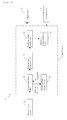
- FIG. 2 The functions that are realized in the calibration mode of the urinary sugar meter 1 when the control unit 5 executes programs are shown in FIG. 2 as a block diagram.
- the programs that are executed here make each of the functions possible, including an output acquisition unit 51, an output value judgment unit 52, a reference value setting unit 53 and a reference fluid detection unit 54. (Naturally, part of these units 51 to 54 can also be constructed using electrical circuits.)
- the output acquisition unit 51 acquires the output value from the urinary sugar sensor 2 by way of the A/D conversion unit when a reference fluid, whose urinary sugar content has a set density, is applied to the urinary sugar sensor 2 .
- the output value judgment unit 52 determines whether or not the output value that is newly acquired from the urinary sugar sensor 2 by the output acquisition unit 51 is suitable as the setting for the measurement reference value (that will be the reference when performing measurement by the urinary sugar sensor 2) based on an output value that has already been acquired fromthe urinary sugar sensor 2 by the output acquisition unit 51.
- the reference value setting unit 53 calibrates the sensitivity of the urinary sugar sensor 2 by setting the measurement reference value using the output value from the urinary sugar sensor 2 that was determined to be suitable as the setting for the measurement reference value.
- This measurement reference value is stored in a reference value memory unit 55 in the EPROM.
- the measurement reference value for measurement of the urinary sugar level in the measurement mode is stored in the reference value memory unit 55 before the urinary sugar meter 1 is shipped. In the measurement mode, the urinary sugar level is measured using this measurement reference value.
- the reference fluid detection unit 54 detects that the reference fluid has been additionally applied.
- the output value judgment unit 52 determines that an output value is not suitable to be set as the measurement reference value, then after this judgment, the user is prompted by way of the display unit 3 to additionally apply reference fluid to the urinary sugar sensor 2.
- the reference fluid detection unit 54 detects when reference fluid has been additionally applied.
- the output acquisition unit 51 uses this additionally applied reference fluid as the object from which another output value is acquired that is different than the aforementioned output value that was previously obtained.
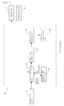
- the control unit 5 executes each process according to the flow shown in the flowchart of FIG. 3 .
- the urinary sugar meter 1 is activated in the measurement mode in step 1 (hereafter, step will be abbreviated as S).
- control unit (CPU) 5 determines whether or not the sensitivity of the urinary sugar sensor 2 must be calibrated according to the number of times counted by the internal counter that the urinary sugar level has been measured. In S2, whether or not it is necessary to calibrate the sensitivity can also be determined by measuring the amount of time that has elapsed since the previous calibration, and judging whether or not that elapsed time has reached a specified amount of time.
- the urinary sugar measurement unit in the control unit 5 measures the urinary sugar level.
- the measurement reference value is stored in the reference value memory unit 55, and the urinary sugar measurement unit uses the measurement reference value that is read from the reference value memory unit 55 and measures the urinary sugar level. The method of measuring the urinary sugar level using this measurement reference value is well known, so a detailed explanation of that method is omitted here.
- the control unit displays the measured urinary sugar level on the display unit 3, and displays guidance instructing the user to perform the cleaning process.
- the control unit displays the measured urinary sugar level on the display unit 3, and displays guidance instructing the user to perform the cleaning process.
- control unit 5 performs control to display guidance on the display unit 3 giving instructions to apply reference fluid on the urinary sugar sensor 2.
- the control unit acquires the output value from the urinary sugar sensor 2.
- the output value from the urinary sugar sensor 2 is acquired as the measurement value of the reference fluid.
- the acquired output value is stored in RAM in time sequence.
- the control unit 5 compares the most recently acquired output value (hereafter, referred to as the 'most recent value') with the output value acquired in the past, and determines whether or not the magnitude of the change between the past output value and the most recent value levels off within an allowable range and whether or not the output value becomes stable.
- the output value from the previous measurement ('previous value') is used as the past output value, and the most recent value is compared with the previous value to determine whether or not the output value is stable. By doing this, the control unit 5 determines whether or not the most recent value is suitable to be used as the measurement reference value.
- control unit 5 takes the limit of the allowable value for the change in output of the reference fluid to be A, and determines whether or not the difference between the previous value and most recent value is this allowable limit value A or less. However, when the output that will become the previous value has not been measured, the measurement reference value that is preset at the time the product is shipped and stored in the reference value memory unit 55 is used as the previous value.
- the control unit 5 determines that the most recent value is suitable to be used as the measurement reference value, and advances to S8.
- the measurement reference value that is already stored in the reference value memory unit 55 is replaced by the most recent value as the new measurement reference value.
- the control unit 5 displays on the display unit 3 that calibration is complete, and after that, when the user presses the power ON/OFF switch, this process ends, and the power to the urinary sugar meter 1 is turned OFF.
- the control unit 5 determines that this most recent value is not suitable to be used as the measurement reference value, and advances to S10. For example, when the necessary amount of reference fluid is not applied, there is a high possibility that the obtained most recent value will be determined as not being suitable to be used as the measurement reference value. Furthermore, cumulative reference fluid measurement is performed according to S10 to S13 and S6. In other words, as a result of this cumulative reference fluid measurement, new reference fluid is further applied to the urinary sugar sensor 2, to which the reference fluid that was applied as instructed by the display in S5 is still adhered, and in S6, the output value from the urinary sugar sensor 2 is obtained.
- the control unit 5 determines whether or not the suitability judgment performed in S7 has been repeatedly performed a specified number of times.
- the specified number of times is preset as the upper limit value of the number of times measurement of the reference fluid is performed in one sensitivity calibration. That is, when an output value that is suitable to be used as the measurement reference value is not obtained even though the reference fluid is continuously measured just the specified number of times, the process ends in error. For example, an event such as when the urinary sugar sensor 2 has deteriorated to the extent that it is not capable of sensitivity calibration, or when the measurement mechanism of the urinary sugar meter 1 is defective, or when the user makes a mistake in the operation of the calibration procedure, could cause the number of judgments in S7 to exceed the upper limit.
- control unit 5 displays guidance on the display unit 3 giving instructions to further apply reference fluid to the urinary sugar sensor 2 to which reference fluid is already applied.
- reference fluid has already been applied to the urinary sugar sensor 2 and reference fluid is adhered to the sensor. The user is then instructed to additionally apply more reference fluid to the urinary sugar sensor 2 in this state.
- the addition of this reference fluid is detected (S13: YES), and the control unit 5 advances to S6. More specifically, the addition of reference fluid in S13 is detected by a small change in the sensor output when reference fluid is additionally applied to the urinary sugar sensor 2. In other words, after the instruction is displayed in S12 to add reference fluid, when the change in the sensor output becomes equal to or greater than a specified threshold value, it is determined that reference fluid was added at the instant that the change in output was detected.
- the output value from the urinary sugar sensor 2 after reference fluid has been additionally applied is acquired, and that output value is then stored. Moreover, this newly acquired output value becomes the most recent value, and the control unit 5 advances to S7 to determine whether or not this most recent value is suitable to be used as the measurement reference value. In one sensitivity calibration of the urinary sugar sensor 2, this judgment of the output value from the urinary sugar sensor 2 and acquiring a new output value is continually repeated until the measurement reference value is finally set and calibration is completed.
- S6 in FIG. 3 corresponds to the output value acquisition unit 51 shown in FIG. 2 .
- S7 in FIG. 3 corresponds to the output value judgment unit 52 in FIG. 2 .
- S8 in FIG. 3 corresponds to the reference value setting unit 53 in FIG. 2 .
- S13 in FIG. 3 corresponds to the reference fluid detection unit 54 in FIG. 2 .
- this urinary sugar meter 1 even when the amount of reference fluid that is applied to the urinary sugar sensor 2 during one measurement of the reference fluid is less than the necessary amount, more reference fluid can be added and the reference fluid can be measured again without having to perform the cleaning process. Depending on the circumstances, this is repeated. Particularly, this addition of reference fluid is made possible by the means for detecting the addition of reference fluid. Through repeated addition of reference fluid, it is possible to finally obtain stable output from the urinary sugar sensor 2.
- FIG. 4A graphically shows the output of the urinary sugar meter 1, and as shown in FIG. 4A , the difference D1 between the sensor output that is obtained in one reference fluid measurement, and the sensor output that is obtained in the next reference fluid measurement becomes smaller as the addition of reference fluid is repeated.
- the urinary meter of a second embodiment of the invention has the construction shown in FIG. 5 . That is, this urinary sugar meter 20 has construction similar to the urinary sugar meter 1 of the first embodiment described above, however, in this urinary sugar meter 20 (in the output acquisition unit 61), setting two operating states during execution of the calibration mode, and switching between these two operating states are the main differences from the urinary sugar meter 1 described above. These two operating states are: a preparation state in which output values are not acquired even though reference fluid may be applied to the urinary sugar sensor (non-acquisition state), and a measurement possible state in which output values are acquired when reference fluid is applied to the urinary sugar sensor (acquisition state).
- the construction and effect of the urinary sugar meter 20 are the same as that of the urinary sugar meter 1 of the first embodiment, so a detailed explanation of them is omitted here.
- the same reference numbers are used for parts that are identical to those of the first embodiment.
- the steps of the flowchart shown in FIG. 6 of the flow of operations of the urinary sugar meter 20 the same reference numbers are given to steps that are the same as those for the urinary sugar meter 1 shown in FIG. 3 .
- one of the buttons on the operation unit 4 of the urinary sugar meter 20 is a calibration button 4a.
- This calibration button 4a is used by the user to input an instruction to change the operating state of the urinary meter 20 (output acquisition unit 61) from the preparation state to the measurement possible state just before reference fluid is applied to the urinary sugar sensor 2.
- the output value acquisition unit 51 changes the operating state from the preparation state to the measurement possible state based on this change instruction. More specifically, after the urinary sugar meter 20 is set to the calibration mode, when the user presses the calibration button 4a one time, the operating state of the urinary sugar meter 20 is changed from the preparation state to the measurement possible state.
- this urinary sugar meter 20 when it is determined in S2 that the sensitivity of the urinary sugar sensor 2 needs to be calibrated (S2: YES) and the urinary sugar meter 20 is switched to the calibration mode, the process from S21 onward that is related to sensitivity calibration is executed. Differing from the urinary sugar meter 1 of the first embodiment, when the urinary sugar meter 20 is shipped, a measurement reference value for measuring the urinary sugar level in the measurement mode is not stored in the reference value memory unit 55. In other words, after shipment of the product, the user purchases the urinary sugar meter 20, and calibration must be performed even when using the urinary sugar meter 20 for the first time.
- the control unit 25 notifies the user that the operating state of the urinary sugar meter 20 is set to the preparation state.
- the control unit 25 displays the display shown in FIG. 7A on the display unit 3. That is, the flashing display 'Preparation in Progress' is displayed on the display unit 3, and this flashing display notifies the user that the operating state of the urinary sugar meter 20 is set to the preparation state.
- the display, 'Checking with the Reference ' is displayed on the display unit 3, and this display notifies the user that the urinary sugar meter 20 is in the calibration mode.
- the control unit 25 determines whether or not the calibration button 4a has been pressed.
- the urinary sugar meter 20 can recognize thereafter when reference fluid is applied to the urinary sugar meter 20 in order to perform sensitivity calibration.
- the control unit 25 returns to S22. In that case, the control unit 25 continues to notify that the operating state is the preparation state.
- the control unit notifies the user by way of the display unit 3 that the operating state of the urinary sugar meter 20 is the measurement possible state.
- control unit 25 may display the display shown in FIG. 7B on the display unit 3.
- a flashing guidance display 'Measurement' and a flashing drop mark (image of a fluid drop) display are displayed on the display unit 3.
- This flashing 'Measurement' display indicates that measurement of the reference fluid is possible, and the flashing drop mark prompts the user to apply reference fluid to the urinary sugar sensor 2.
- control unit 25 has an internal timer (not shown in the figure), and is capable of measuring the wait time for waiting for detection of the reference fluid.
- This wait time can be set to 10 seconds for example, and preferably is set between 5 seconds and 60 seconds.
- the control unit 25 determines whether or not reference fluid has been applied to the urinary sugar sensor 2. This detection can be according to a small change in sensor output that occurs when reference fluid is applied to the urinary sugar sensor 2.
- the control unit 25 acquires the output value from the urinary sugar sensor 2 as in the case of the urinary sugar meter 1 of the first embodiment (see S6 of FIG. 3 ), and stores that output value in RAM in time sequence. When acquiring this output value, the control unit 25 can notify the user that the urinary sugar sensor 2 is measuring the urinary sugar level.
- the control unit 25 displays the display shown in FIG. 7C on the display unit 3.
- the drip mark display is no longer displayed, and the 'Measurement' guidance display changes from a flashing display to being continuously lit up, and furthermore, measurement bars (three bars that run horizontally) appear.
- measurement bars three bars that run horizontally appear.
- the number of lit up measurement bars decreases at set intervals.
- all three of the measurement bars will be lit up again. This kind of measurement bar display continues until another display, such as that in S23, S28 or S11, is displayed.
- control unit 25 After the output value has been acquired and stored in memory in S25, the control unit 25 changes the operating state of the urinary sugar meter 20 from the measurement possible state to the preparation state, and prevents the acquisition of output values. After the processing in S25, the control unit 25 advances to S27.
- control unit 25 when application of reference fluid was not detected (S24: NO), in S26, the control unit 25, according to the clock count of the timer, further determines whether or not the wait time has become a specified time. When the wait time has not reached the specified time (S26: NO), the control unit 25 returns to S24 and waits for reference fluid to be detected. On the other hand, when the wait time has reached the specified time (S26: YES), the control unit 25 advances to S25 and performs the processes described above such as acquiring the output value of the urinary sugar sensor 2.
- the control unit 25 advances to S27.
- control unit 25 determines whether or not a previous value is stored in memory with respect to the acquired output value, or in other words, the most recent value.
- the previous value is stored in memory (S27: YES)
- the process from S7 onward is executed.
- the control unit 25 determines whether the most recent value is suitable to be used as the measurement reference value as in the case of the urinary sugar meter 1 of the first embodiment.
- the control unit 25 determines in S10 whether the number of times the suitability of the most recent value has been judged has reached a specified number of times, and in S11, displays an error display or the like.
- the control unit 25 stores the most recent value in memory as the measurement reference value, and in S28 displays a display indicating that calibration is complete.
- This calibration complete display may be a display as shown in FIG. 7D . That is, here, instead of the 'Checking with the Reference' text display in the display of S21 (see FIG. 7A ), the display of S23 (see FIG. 7B ) and the display in S25 (see FIG. 7C ), a flashing text display 'Calibration Complete' is displayed. This 'Calibration Complete' display notifies the user that calibration is complete.
- the output value fromthe urinary sugar sensor 20 is not stable. Since the unstable first output value is not used as the measurement reference value setting, the reliability of the measurement reference value that is set in sensitivity calibration is improved.
- S25 and S26 correspond to the output value acquisition unit 61 in FIG. 5 .
- S7 and S27 in FIG. 6 correspond to the output value judgment unit 52 in FIG. 5 .
- S8 in FIG. 6 corresponds to the reference value setting unit 53 in FIG. 5 .
- S24 in FIG. 6 (particularly from the second time on) corresponds to the reference fluid detection unit 54 in FIG. 5 .
- the urinary sugar meter 20 As in the case of the urinary sugar meter 1 of the first embodiment, with this urinary sugar meter 20 as well, when it is determined from an output value already obtained from the urinary sugar sensor 2 that the output value of the urinary sugar sensor 2 is not suitable to be used as the reference value in one sensitivity calibration of the urinary sugar sensor 2, after that reference fluid is additionally applied to the urinary sugar sensor 2 and detected without performing the cleaning process. Therefore, when compared with a conventional measurement device in which the cleaning process must be performed after each time an output value is obtained, it is possible to calibrate the sensitivity of a biosensor more easily and in a shorter amount of time.
- the additional application of reference fluid to the urinary sugar sensor 2 is detected by minute change in the output value of the urinary sugar sensor 2. Differing from this, it is possible to use a temperature sensor that detects the temperature of the urinary sugar sensor 2, and to detect the addition of reference fluid by detecting change in the detected temperature of the urinary sugar sensor 2.
- an impact sensor that detects physical impact to the urinary sugar sensor 2, and to detect the addition of reference fluid by that detected impact.
- an addition confirmation button on the operation unit 4 that is used by the user in order to input confirmation immediately after reference fluid has been applied to the urinary sugar sensor 2 that reference fluid has been applied to the urinary sensor 2. At this point, the addition of reference fluid is detected when the user actually presses this addition confirmation button in order to confirm that reference fluid has been added.
- this button When using the addition confirmation button, in addition to the effect that is obtained when using the aforementioned temperature sensor or the like, this button has the merit in that it is easy for the user to know which operation in a specified operating procedure is currently being performed.
- the biosensor was a urinary sugar sensor, however, the biosensor can also be another sensor that requires calibration using a reference fluid.
- An example of a portable urinary sugar meter was given as the test fluid measurement device, however, it is also possible to use another installable type of test fluid measurement device.
- the test fluidmeasurement device referred to here includes clinical testing devices.
Landscapes
- Health & Medical Sciences (AREA)
- Engineering & Computer Science (AREA)
- Life Sciences & Earth Sciences (AREA)
- Biomedical Technology (AREA)
- Urology & Nephrology (AREA)
- Physics & Mathematics (AREA)
- Chemical & Material Sciences (AREA)
- Molecular Biology (AREA)
- Hematology (AREA)
- Biophysics (AREA)
- Food Science & Technology (AREA)
- Medicinal Chemistry (AREA)
- Analytical Chemistry (AREA)
- Biochemistry (AREA)
- General Health & Medical Sciences (AREA)
- General Physics & Mathematics (AREA)
- Immunology (AREA)
- Pathology (AREA)
- Investigating Or Analysing Biological Materials (AREA)
Abstract
Description
- The present invention relates to a test fluid measurement device and sensitivity calibration method thereof that uses a reference fluid having a certain substance that is set to a specified density in order to calibrate the sensitivity of a biosensor that measures the amount of the certain substance that is contained in a test fluid.
- A known example of this kind of measurement device that requires calibration of its biosensor, is a urine measurement device that measures the urinary sugar level of urine that is directly applied to the biosensor during urination (refer to
Japanese patent application H9-297120 - Generally, this kind of measurement device determines whether or not calibration of the sensitivity is necessary according to the frequency of use of the biosensor, and when calibration is necessary, notifies and prompts the user to perform calibration. In this calibration of the sensitivity, output from the biosensor for a reference fluid is obtained. That is, when measuring a reference fluid, the user drips some reference fluid from a dropper shaped container onto the biosensor, and the output from the biosensor after doing this is obtained by the measurement device that comprises that biosensor.
- After measuring this reference fluid, it is necessary that the biosensor, (1) first, be cleaned in a cleaning fluid, (2) then immersed in a preservative fluid such as a buffer fluid, and (3) allowed time for the baseline of the output to become stable. (Hereafter, the process of these steps (1) to (3) will be referred to as the 'cleaning process'.)
- [Patent Document 1]
Japanese patent application H9-297120 - However, normally, sensitivity calibration is seldom completed after one measurement of the reference fluid. For example, when only a small amount of reference fluid that is applied to the biosensor, that amount might not be enough to satisfy the required amount needed for measurement. In that case, the output value from the biosensor is not used for sensitivity calibration and the measurement device displays a message that measurement of the reference fluid must be performed again.
- Despite this, the cleaning process was performed each time the reference fluid was applied. This is so that no reference fluid remains in the biosensor in order that the measurement of the reference fluid performed next will be performed under the same measurement conditions. In this kind of sensitivity calibration, the work of performing the cleaning process must be performed, which takes time.
- The object of the present invention is to provide a test fluid measurement device and sensitivity calibration method capable of calibrating the sensitivity of a biosensor easily and in a short amount of time.
- The test fluid measurement device according to a first claim of the invention comprises an output acquisition means and a setting means. The output acquisition means for acquiring the output value of a biosensor that measures the amount of a certain substance that is contained in a test fluid when a reference fluid containing said certain substance that is set to a specified density is applied to the biosensor. The setting means calibrates the sensitivity of the biosensor by setting a reference value that will be a reference for measurement by the biosensor using the output value that was acquired from the biosensor by the output acquisition means.
The test fluid measurement device also comprises a judgment means and a detection means. This judgment means uses an output value that is already acquired from the biosensor by the output acquisition means for determining whether or not an output value that is newly acquired from the biosensor by the output acquisition means during sensitivity calibration by the setting means is suitable to be used as the setting for the reference value. The detection means detects when the reference fluid, which is the subject of acquiring another output value by the output acquisition means, is additionally applied to the biosensor after the judgment means determines that an output value is not suitable as the setting for the reference value.
The test fluid measurement device according to a second claim is the test fluid measurement device of the first claim, wherein the setting means sets the output value from the biosensor, which was determined by the judgment means to be suitable as the setting for the reference value, as the reference value.
The test fluid measurement device according to a third claim is the test fluid measurement device ofclaim 1 in which the setting means is constructed as follows. That is, the setting means sets the average of the output values, which were acquired by the output acquisition means a specified number of times and were determined by the judgment means to be suitable as the setting for the reference value, as the reference value.
The test fluid measurement device according to a fourth claim is the test fluid measurement device of any one of theclaims 1 to 3 in which the judgment means is constructed as follows. That is, the judgment means determines that the output value from the biosensor that was acquired the first time by the output acquisition means during the sensitivity calibration by the setting means is not suitable as the setting for the reference value.
The test fluid measurement device according to a fifth claim is the test fluid measurement device of any one of theclaims 1 to 3 in which the detection means is constructed as follows. In other words, the detection means detects that the reference fluid has been additionally applied to the biosensor due to change in the output value from the biosensor that is acquired by the output acquisition means.
The test fluid measurement device according to a sixth claim is the test fluid measurement device of any one of theclaims 1 to 3, further comprising temperature detection means for detecting the temperature of the biosensor. In this case, the detection means detects that the reference fluid has been additionally applied to the biosensor due to change in the temperature of the biosensor that is detected by the temperature detection means.
The test fluid measurement device according to a seventh claim is the test fluid measurement device of any one of theclaims 1 to 3, further comprising impact detection means for detecting physical impact that is applied to the biosensor. In this case, the detection means detects that the reference fluid has been additionally applied to the biosensor due to impact to the biosensor that is detected by the impact detection sensor.
The test fluid measurement device according to an eighth claim is the test fluid measurement device of any one of theclaims 1 to 3, further comprising addition confirmation means for a user to input confirmation that the reference fluid has been additionally applied to the biosensor. In this case, the detection means detects that the reference fluid has been additionally applied to the biosensor due to the addition confirmation that is input from the addition confirmation means.
The test fluid measurement device according to a ninth claim is the test fluid measurement device of any one of theclaims 1 to 3, wherein the output acquisition means has two operating states; a non acquisition state and an acquisition state. The non-acquisition state is a state in which the output value from the biosensor is not acquired even though the reference fluid is applied, and the acquisition state is a state in which the output value from the biosensor is acquired when the reference fluid is applied. Here, an instruction input means is used for a user to input an instruction to change the operating state of the output acquisition means from the non-acquisition state to the acquisition state. The output acquisition means changes the operating state from the non acquisition state to the acquisition state based on the change instruction that is input from this instruction input means.
The test fluid measurement device according to a tenth claim is the test fluid measurement device of claim 9, wherein the output acquisition means acquires an output value from the biosensor after a specified amount of time has elapsed from the instant when the operating state of the output acquisition means changes from the non acquisition state to the acquisition state.
The test fluid measurement device according to an eleventh claim is the test fluid measurement device of claim 9, further comprising notification means for notifying that the operating state of the output acquisition means is either the non acquisition state or the acquisition state.
The test fluid measurement method of a twelfth embodiment of the invention is a sensitivity calibration method for calibrating the sensitivity of a biosensor by acquiring the output value of a biosensor that measures the amount of a certain substance that is contained in a test fluid when a reference fluid containing said certain substance that is set to a specified density is applied to the biosensor, and setting a reference value that will be a reference for measurement by the biosensor using the acquired output value.
During sensitivity calibration, this sensitivity calibration method: (1) uses an output value that has already been acquired to determine whether or not an output value that is newly acquired from the biosensor is suitable to be used as the setting for the reference value; and (2) detects when the reference fluid, which is the subject of acquiring another output value, is additionally applied to the biosensor after an output value is determined not to be suitable as the setting for the reference value. - With the test fluid measurement device of this invention, when it is determined during sensitivity calibration of the biosensor that an output value from the biosensor is not suitable as the setting for the reference value (measurement reference value), after that, the additional application of more reference fluid is detected without performing the cleaning process. Also, after the reference fluid has been additionally applied, another output value from the biosensor is acquired.
- Therefore, compared with a conventional measurement device in which the cleaning process was always performed after an output value was obtained, this device is capable of performing sensitivity calibration of a biosensor more easily and in a shorter period of time.
-
-
FIG. 1 is a drawing showing the external appearance of a urinary sugar meter of a first embodiment of the invention. -
FIG. 2 is a block diagram showing the construction of the electrical circuits for sensitivity calibration of the urinary sugar meter. -
FIG. 3 is a first flowchart for explaining the operation during sensitivity calibration of the urinary sugar meter. -
FIG. 4 is a drawing for explaining the effect of sensitivity calibration of the urinary sugar meter. -
FIG. 5 is a block diagram showing the construction related to the sensitivity calibration of a urinary sugar meter of a second embodiment of the invention. -
FIG. 6 is a second flowchart for explaining the operation during sensitivity calibration of the urinary sugar meter. -
FIGS. 7A to 7D are drawings showing examples of the displays on a display during sensitivity calibration of the urinary sugar meter. - The preferred embodiments of the invention will be explained with reference to the drawings.
- As a first embodiment of the invention, a
urinary sugar meter 1, which is a test fluid measurement device that uses a urinary sugar sensor as the biosensor, will be explained. As shown inFIG. 1 andFIG. 2 , theurinary sugar meter 1 comprises: aurinary sugar sensor 2, adisplay unit 3, anoperation unit 4 and acontrol unit 5. Theurinary sugar sensor 2 electrochemically detects (measures) the amount of sugar content in the urine of the test fluid. The part surrounding thisurinary sugar sensor 2 is concave shaped so that it can hold the reference fluid. Theurinary sugar sensor 2 is located at the bottom of this concave shaped section. - The
display unit 3 displays measurement values, judgment results and operation guidance. Theoperation unit 4 includes a power ON/OFF switch, and by pressing the power ON/OFF switch the power to theurinary sugar meter 1 is turned from OFF to ON, and by pressing the power ON/OFF switch again, the power to the urinary sugar meter is turned OFF. - The
control unit 5 comprises a CPU, RAM, ROM, EPROM, input/output interface and the like, and performs overall control of the urinary sugar meter, including the display on thedisplay unit 3 and input from theoperation unit 4. In addition, theurinary sugar meter 1 comprises an A/D conversion unit (not shown in the figure), and that A/D conversion unit converts the signal that is detected by theurinary sugar sensor 2 to digital data and outputs the result to thecontrol unit 5. - More specifically, the
urinary sugar meter 1 has a measurement mode for measuring the urinary sugar level, and a calibration mode for calibrating the sensitivity of theurinary sugar sensor 2, and thecontrol unit 5 is capable of switching between the measurement mode and the calibration mode. - The control unit (CPU) 5 comprises a urinary sugar measurement unit and a counter that are used in the measurement mode of the
urinary sugar meter 1. The urinary sugar measurement unit performs overall control of the measurement of the urinary sugar level in the measurement mode, and the counter counts the number of times that the urinary sugar measurement unit has measured the urinary sugar level as a value that corresponds to the frequency of use of theurinary sugar sensor 2. Furthermore, when the number of times that the urinary sugar level has been measured, which is counted by the counter, reaches a specified number of times, theurinary sugar meter 1 determines that calibration is necessary', and displays a message on thedisplay unit 3 indicating that calibration is necessary and to change to the calibration mode. - The functions that are realized in the calibration mode of the
urinary sugar meter 1 when thecontrol unit 5 executes programs are shown inFIG. 2 as a block diagram. The programs that are executed here make each of the functions possible, including anoutput acquisition unit 51, an outputvalue judgment unit 52, a referencevalue setting unit 53 and a referencefluid detection unit 54. (Naturally, part of theseunits 51 to 54 can also be constructed using electrical circuits.) - In the calibration mode, the
output acquisition unit 51 acquires the output value from theurinary sugar sensor 2 by way of the A/D conversion unit when a reference fluid, whose urinary sugar content has a set density, is applied to theurinary sugar sensor 2 . The outputvalue judgment unit 52 then determines whether or not the output value that is newly acquired from theurinary sugar sensor 2 by theoutput acquisition unit 51 is suitable as the setting for the measurement reference value (that will be the reference when performing measurement by the urinary sugar sensor 2) based on an output value that has already been acquired fromtheurinary sugar sensor 2 by theoutput acquisition unit 51. - The reference
value setting unit 53 calibrates the sensitivity of theurinary sugar sensor 2 by setting the measurement reference value using the output value from theurinary sugar sensor 2 that was determined to be suitable as the setting for the measurement reference value. This measurement reference value is stored in a referencevalue memory unit 55 in the EPROM. The measurement reference value for measurement of the urinary sugar level in the measurement mode is stored in the referencevalue memory unit 55 before theurinary sugar meter 1 is shipped. In the measurement mode, the urinary sugar level is measured using this measurement reference value. - Particularly, when the reference
value setting unit 53 calibrates the sensitivity of theurinary sugar sensor 2 once, the referencefluid detection unit 54 detects that the reference fluid has been additionally applied. In other words, in thisurinary sugar meter 1, when the outputvalue judgment unit 52 determines that an output value is not suitable to be set as the measurement reference value, then after this judgment, the user is prompted by way of thedisplay unit 3 to additionally apply reference fluid to theurinary sugar sensor 2. Moreover, the referencefluid detection unit 54 detects when reference fluid has been additionally applied. When calibrating the sensitivity one time, theoutput acquisition unit 51 uses this additionally applied reference fluid as the object from which another output value is acquired that is different than the aforementioned output value that was previously obtained. - In the
urinary sugar meter 1 having this construction, thecontrol unit 5 executes each process according to the flow shown in the flowchart ofFIG. 3 . When the power to theurinary sugar meter 1 is turned OFF and the user presses the power ON/OFF switch on theoperation unit 4, theurinary sugar meter 1 is activated in the measurement mode in step 1 (hereafter, step will be abbreviated as S). - In S2, the control unit (CPU) 5 determines whether or not the sensitivity of the
urinary sugar sensor 2 must be calibrated according to the number of times counted by the internal counter that the urinary sugar level has been measured. In S2, whether or not it is necessary to calibrate the sensitivity can also be determined by measuring the amount of time that has elapsed since the previous calibration, and judging whether or not that elapsed time has reached a specified amount of time. - When it is determined in S2 that sensitivity calibration is not necessary, or in other words, when it is determined that the number of times that the urinary sugar level has been measured is less than a specified number of times (S2: NO), in S3, the urinary sugar measurement unit in the
control unit 5 measures the urinary sugar level. At this point, the measurement reference value is stored in the referencevalue memory unit 55, and the urinary sugar measurement unit uses the measurement reference value that is read from the referencevalue memory unit 55 and measures the urinary sugar level. The method of measuring the urinary sugar level using this measurement reference value is well known, so a detailed explanation of that method is omitted here. - When this measurement of the urinary sugar level is completed, next, in S4, the control unit displays the measured urinary sugar level on the
display unit 3, and displays guidance instructing the user to perform the cleaning process. After the user completes the cleaning process, by pressing the power ON/OFF switch, this process ends, and the power to theurinary sugar meter 1 is turned OFF. - On the other hand, in the aforementioned S2, when it is determined that calibration is necessary, or in other words, when the number of times that the urinary sugar level has been measured is equal to or greater than a specified number of times (S2: YES), the
urinary sugar meter 1 is switched to the calibration mode, and the sensitivity calibration process starting from S5 is executed. - First, in S5, the
control unit 5 performs control to display guidance on thedisplay unit 3 giving instructions to apply reference fluid on theurinary sugar sensor 2. In addition, in S6, the control unit acquires the output value from theurinary sugar sensor 2. In other words, when the user applies reference fluid to theurinary sugar sensor 2 as instructed by the guidance display on thedisplay unit 3, the output value from theurinary sugar sensor 2 is acquired as the measurement value of the reference fluid. At this time, the acquired output value is stored in RAM in time sequence. - Next, in S7, the
control unit 5 compares the most recently acquired output value (hereafter, referred to as the 'most recent value') with the output value acquired in the past, and determines whether or not the magnitude of the change between the past output value and the most recent value levels off within an allowable range and whether or not the output value becomes stable. Here, the output value from the previous measurement ('previous value') is used as the past output value, and the most recent value is compared with the previous value to determine whether or not the output value is stable. By doing this, thecontrol unit 5 determines whether or not the most recent value is suitable to be used as the measurement reference value. - In other words, the
control unit 5 takes the limit of the allowable value for the change in output of the reference fluid to be A, and determines whether or not the difference between the previous value and most recent value is this allowable limit value A or less. However, when the output that will become the previous value has not been measured, the measurement reference value that is preset at the time the product is shipped and stored in the referencevalue memory unit 55 is used as the previous value. - When the difference is equal to or less than the allowable limit value A (S7: YES), the
control unit 5 determines that the most recent value is suitable to be used as the measurement reference value, and advances to S8. In S8, the measurement reference value that is already stored in the referencevalue memory unit 55 is replaced by the most recent value as the new measurement reference value. Also, in S9, thecontrol unit 5 displays on thedisplay unit 3 that calibration is complete, and after that, when the user presses the power ON/OFF switch, this process ends, and the power to theurinary sugar meter 1 is turned OFF. - On the other hand, when the difference is greater than the allowable limit value A (S7: NO), the
control unit 5 determines that this most recent value is not suitable to be used as the measurement reference value, and advances to S10. For example, when the necessary amount of reference fluid is not applied, there is a high possibility that the obtained most recent value will be determined as not being suitable to be used as the measurement reference value. Furthermore, cumulative reference fluid measurement is performed according to S10 to S13 and S6. In other words, as a result of this cumulative reference fluid measurement, new reference fluid is further applied to theurinary sugar sensor 2, to which the reference fluid that was applied as instructed by the display in S5 is still adhered, and in S6, the output value from theurinary sugar sensor 2 is obtained. - First, in S10, the
control unit 5 determines whether or not the suitability judgment performed in S7 has been repeatedly performed a specified number of times. Here, the specified number of times is preset as the upper limit value of the number of times measurement of the reference fluid is performed in one sensitivity calibration. That is, when an output value that is suitable to be used as the measurement reference value is not obtained even though the reference fluid is continuously measured just the specified number of times, the process ends in error. For example, an event such as when theurinary sugar sensor 2 has deteriorated to the extent that it is not capable of sensitivity calibration, or when the measurement mechanism of theurinary sugar meter 1 is defective, or when the user makes a mistake in the operation of the calibration procedure, could cause the number of judgments in S7 to exceed the upper limit. - In this S10, when it is determined that the number of judgments in S7 has reached the specified number of times (S10: YES), in S11, the
control unit 5 displays on thedisplay unit 3 that there was an error. After that, when the user presses the power ON/OFF switch, the process ends and the power to theurinary sugar meter 1 is turned OFF. - However, in S10, when it is determined that the number of judgments has not yet reached the specified number of times (S10 : NO), in S12, the
control unit 5 displays guidance on thedisplay unit 3 giving instructions to further apply reference fluid to theurinary sugar sensor 2 to which reference fluid is already applied. In other words, according to the display in S5, reference fluid has already been applied to theurinary sugar sensor 2 and reference fluid is adhered to the sensor. The user is then instructed to additionally apply more reference fluid to theurinary sugar sensor 2 in this state. - After the user adds and applies reference fluid to this
urinary sugar sensor 2, theninS13, the addition of this reference fluid is detected (S13: YES), and thecontrol unit 5 advances to S6. More specifically, the addition of reference fluid in S13 is detected by a small change in the sensor output when reference fluid is additionally applied to theurinary sugar sensor 2. In other words, after the instruction is displayed in S12 to add reference fluid, when the change in the sensor output becomes equal to or greater than a specified threshold value, it is determined that reference fluid was added at the instant that the change in output was detected. - Next, in S6, the output value from the
urinary sugar sensor 2 after reference fluid has been additionally applied is acquired, and that output value is then stored. Moreover, this newly acquired output value becomes the most recent value, and thecontrol unit 5 advances to S7 to determine whether or not this most recent value is suitable to be used as the measurement reference value. In one sensitivity calibration of theurinary sugar sensor 2, this judgment of the output value from theurinary sugar sensor 2 and acquiring a new output value is continually repeated until the measurement reference value is finally set and calibration is completed. - In this embodiment, the correlation between the steps shown in the flowchart of
FIG. 3 and each of the units shown in the block diagram ofFIG. 2 , is as described below. In other words, S6 inFIG. 3 corresponds to the outputvalue acquisition unit 51 shown inFIG. 2 . S7 inFIG. 3 corresponds to the outputvalue judgment unit 52 inFIG. 2 . S8 inFIG. 3 corresponds to the referencevalue setting unit 53 inFIG. 2 . Also, S13 inFIG. 3 corresponds to the referencefluid detection unit 54 inFIG. 2 . - When a newly acquired output value from the
urinary sugar sensor 2 is determined not to be suitable as the setting for the reference value during one calibration of the sensitivity of theurinary sugar sensor 2 and judgment is performed from an already acquired output value from theurinary sugar sensor 2, after that theurinary sugar meter 1 of this embodiment detects that more reference fluid is additionally applied to theurinary sugar sensor 2 as is without performing the cleaning process. Furthermore, with the reference fluid additionally applied to the sensor, another output value is acquired from theurinary sugar sensor 2. Therefore, compared with a conventional measurement device in which the cleaning process must be performed after an output value has been obtained, it is possible to calibrate the sensitivity of a biosensor more easily and in a shorter amount of time. - Generally, in many conventional measurement devices, when it is determined that sensitivity calibration is necessary, it is not possible to measure the test fluid until that calibration is completed. For example, when there is a notice indicating that it was determined that sensitivity calibration is necessary just at the timing when the test fluid is to be measured, particularly in the case of a urine measurement device, the user had to refrain from urinating until calibration was complete, or the urinary sugar measurement had to be terminated. It is possible to collect the urine in a separate container, however this is troublesome. With this
urinary sugar meter 1, sensitivity calibration is performed simply, so these kinds of inconveniences do not occur. - Moreover, with this
urinary sugar meter 1, even when the amount of reference fluid that is applied to theurinary sugar sensor 2 during one measurement of the reference fluid is less than the necessary amount, more reference fluid can be added and the reference fluid can be measured again without having to perform the cleaning process. Depending on the circumstances, this is repeated. Particularly, this addition of reference fluid is made possible by the means for detecting the addition of reference fluid. Through repeated addition of reference fluid, it is possible to finally obtain stable output from theurinary sugar sensor 2. - More specifically,
FIG. 4A graphically shows the output of theurinary sugar meter 1, and as shown inFIG. 4A , the difference D1 between the sensor output that is obtained in one reference fluid measurement, and the sensor output that is obtained in the next reference fluid measurement becomes smaller as the addition of reference fluid is repeated. - On the other hand, with a conventional urine measurement device, in one reference fluid measurement, in cases such as when the amount of reference fluid that is applied to the urinary sugar sensor in one reference fluid measurement is less than the necessary amount, the cleaning process is performed in preparation for the next reference fluid measurement.
- As shown in
FIG. 4B , when using a conventional urine measurement device, there is a high possibility that each time reference fluid measurement is performed, there will be larger dispersion in the difference D2 between the sensor output that is obtained in one reference fluid measurement and the sensor output that is obtained in the next reference fluid measurement than with theurinary sugar meter 1 of this invention. Fluid that adheres to the urinary sugar sensor and is saved during the cleaning process changes the physical properties of the reference fluid, and this changes becomes a major cause of the dispersion. - The urinary meter of a second embodiment of the invention has the construction shown in
FIG. 5 . That is, thisurinary sugar meter 20 has construction similar to theurinary sugar meter 1 of the first embodiment described above, however, in this urinary sugar meter 20 (in the output acquisition unit 61), setting two operating states during execution of the calibration mode, and switching between these two operating states are the main differences from theurinary sugar meter 1 described above. These two operating states are: a preparation state in which output values are not acquired even though reference fluid may be applied to the urinary sugar sensor (non-acquisition state), and a measurement possible state in which output values are acquired when reference fluid is applied to the urinary sugar sensor (acquisition state). - Other than the construction and effect of the
urinary sugar meter 20 explained here, the construction and effect of theurinary sugar meter 20 are the same as that of theurinary sugar meter 1 of the first embodiment, so a detailed explanation of them is omitted here. Of the components of theurinary sugar meter 20 shown inFIG. 5 , the same reference numbers are used for parts that are identical to those of the first embodiment. Of the steps of the flowchart shown inFIG. 6 of the flow of operations of theurinary sugar meter 20, the same reference numbers are given to steps that are the same as those for theurinary sugar meter 1 shown inFIG. 3 . - As shown in
FIG. 5 , one of the buttons on theoperation unit 4 of theurinary sugar meter 20 is acalibration button 4a. Thiscalibration button 4a is used by the user to input an instruction to change the operating state of the urinary meter 20 (output acquisition unit 61) from the preparation state to the measurement possible state just before reference fluid is applied to theurinary sugar sensor 2. The outputvalue acquisition unit 51 changes the operating state from the preparation state to the measurement possible state based on this change instruction. More specifically, after theurinary sugar meter 20 is set to the calibration mode, when the user presses thecalibration button 4a one time, the operating state of theurinary sugar meter 20 is changed from the preparation state to the measurement possible state. - The features of this
urinary sugar meter 20 are explained in more detail. InFIG. 6 , when it is determined in S2 that the sensitivity of theurinary sugar sensor 2 needs to be calibrated (S2: YES) and theurinary sugar meter 20 is switched to the calibration mode, the process from S21 onward that is related to sensitivity calibration is executed. Differing from theurinary sugar meter 1 of the first embodiment, when theurinary sugar meter 20 is shipped, a measurement reference value for measuring the urinary sugar level in the measurement mode is not stored in the referencevalue memory unit 55. In other words, after shipment of the product, the user purchases theurinary sugar meter 20, and calibration must be performed even when using theurinary sugar meter 20 for the first time. - In the sensitivity calibration, first, in S21, the
control unit 25 notifies the user that the operating state of theurinary sugar meter 20 is set to the preparation state. For example, thecontrol unit 25 displays the display shown inFIG. 7A on thedisplay unit 3. That is, the flashing display 'Preparation in Progress' is displayed on thedisplay unit 3, and this flashing display notifies the user that the operating state of theurinary sugar meter 20 is set to the preparation state. Moreover, as shown inFIG. 7A , in addition to this display indicating the preparation state, the display, 'Checking with the Reference ' is displayed on thedisplay unit 3, and this display notifies the user that theurinary sugar meter 20 is in the calibration mode. - Next, in S22, the
control unit 25 determines whether or not thecalibration button 4a has been pressed. By pressing thecalibration button 4a, the urinary sugar meter 20 (control unit 25) can recognize thereafter when reference fluid is applied to theurinary sugar meter 20 in order to perform sensitivity calibration. In other words, when thecalibration button 4a is not pressed (S22: NO), thecontrol unit 25 returns to S22. In that case, thecontrol unit 25 continues to notify that the operating state is the preparation state. On the other hand, when thecalibration button 4a is pressed (S22: YES), the operating state of theurinary sugar meter 20 changes from the preparation state to the measurement possible state, and then in S23, the control unit notifies the user by way of thedisplay unit 3 that the operating state of theurinary sugar meter 20 is the measurement possible state. - For example, the
control unit 25 may display the display shown inFIG. 7B on thedisplay unit 3. At this time, a flashing guidance display 'Measurement' and a flashing drop mark (image of a fluid drop) display are displayed on thedisplay unit 3. This flashing 'Measurement' display indicates that measurement of the reference fluid is possible, and the flashing drop mark prompts the user to apply reference fluid to theurinary sugar sensor 2. - Together with this kind of notification of the measurement possible state, the instant that the operating state changed is stored in memory. In other words, the
control unit 25 has an internal timer (not shown in the figure), and is capable of measuring the wait time for waiting for detection of the reference fluid. This wait time can be set to 10 seconds for example, and preferably is set between 5 seconds and 60 seconds. - As shown in
FIG. 7B , while the notice is displayed on thedisplay unit 3 that indicates that the operating status is the measurement possible state, in S24, thecontrol unit 25 determines whether or not reference fluid has been applied to theurinary sugar sensor 2. This detection can be according to a small change in sensor output that occurs when reference fluid is applied to theurinary sugar sensor 2. - When it is detected that reference fluid has been applied (S24: YES), in S25, the
control unit 25 acquires the output value from theurinary sugar sensor 2 as in the case of theurinary sugar meter 1 of the first embodiment (see S6 ofFIG. 3 ), and stores that output value in RAM in time sequence. When acquiring this output value, thecontrol unit 25 can notify the user that theurinary sugar sensor 2 is measuring the urinary sugar level. - For example, the
control unit 25 displays the display shown inFIG. 7C on thedisplay unit 3. In other words, here the drip mark display is no longer displayed, and the 'Measurement' guidance display changes from a flashing display to being continuously lit up, and furthermore, measurement bars (three bars that run horizontally) appear. At first all three of the measurement bars are lit up, and the number of lit up measurement bars decreases at set intervals. When all three of the measurement bars have gone off, all three of the measurement bars will be lit up again. This kind of measurement bar display continues until another display, such as that in S23, S28 or S11, is displayed. - After the output value has been acquired and stored in memory in S25, the
control unit 25 changes the operating state of theurinary sugar meter 20 from the measurement possible state to the preparation state, and prevents the acquisition of output values. After the processing in S25, thecontrol unit 25 advances to S27. - On the other hand, in S24, when application of reference fluid was not detected (S24: NO), in S26, the
control unit 25, according to the clock count of the timer, further determines whether or not the wait time has become a specified time. When the wait time has not reached the specified time (S26: NO), thecontrol unit 25 returns to S24 and waits for reference fluid to be detected. On the other hand, when the wait time has reached the specified time (S26: YES), thecontrol unit 25 advances to S25 and performs the processes described above such as acquiring the output value of theurinary sugar sensor 2. - At this point, after a specified amount of time has elapsed from the time when the operating state of the
urinary sugar meter 20 changes fromthe preparation state to the measurement possible state, the output value fromtheurinary sugar sensor 2 is acquired. That is, it is considered that reference fluid has been applied to theurinary sugar sensor 2 even though the application of reference fluid was not detected in S24. After that, thecontrol unit 25 advances to S27. - By regarding that reference fluid has been applied to the
urinary sugar sensor 2 after a specified amount of time has elapsed, it is possible to avoid the operation error of theurinary sugar meter 20 not being able to detect the output value from theurinary sugar sensor 2, even though the user has applied reference fluid. - In S27, the
control unit 25 determines whether or not a previous value is stored in memory with respect to the acquired output value, or in other words, the most recent value. When the previous value is stored in memory (S27: YES), the process from S7 onward is executed. - In other words, in S7, the
control unit 25 determines whether the most recent value is suitable to be used as the measurement reference value as in the case of theurinary sugar meter 1 of the first embodiment. When the most recent value is not suitable to be used as the measurement reference value (S7: NO), then, as in the case of theurinary sugar meter 1, thecontrol unit 25 determines in S10 whether the number of times the suitability of the most recent value has been judged has reached a specified number of times, and in S11, displays an error display or the like. - On the other hand, when the most recent value is suitable to be used as the measurement reference value (S7: YES), then as in the case of the
urinary sugar meter 1, in S8 thecontrol unit 25 stores the most recent value in memory as the measurement reference value, and in S28 displays a display indicating that calibration is complete. This calibration complete display may be a display as shown inFIG. 7D . That is, here, instead of the 'Checking with the Reference' text display in the display of S21 (seeFIG. 7A ), the display of S23 (seeFIG. 7B ) and the display in S25 (seeFIG. 7C ), a flashing text display 'Calibration Complete' is displayed. This 'Calibration Complete' display notifies the user that calibration is complete. - Contrary to the process performed from S7 onward, in S27, when the most recent value is not stored in memory (S27: NO), that is, when the reference fluid measurement is performed for the first time in a sensitivity calibration, processing proceeds as though the output value (most recent value) is not suitable to be used as the measurement reference value. In other words, in this case, in S7 determining whether or not the most recent value is suitable to be used as the measurement reference value is not performed, and from S21 onward, the second reference fluid measurement is performed while additionally applying reference fluid.
- In the first reference fluid measurement in one sensitivity calibration, it is presumedthat the output value fromthe
urinary sugar sensor 20 is not stable. Since the unstable first output value is not used as the measurement reference value setting, the reliability of the measurement reference value that is set in sensitivity calibration is improved. - In each of the steps of the flowchart of
FIG. 6 , the correlation with each of the parts of the block diagram ofFIG. 5 is as follows. InFIG. 6 , S25 and S26 correspond to the outputvalue acquisition unit 61 inFIG. 5 . S7 and S27 inFIG. 6 correspond to the outputvalue judgment unit 52 inFIG. 5 . S8 inFIG. 6 corresponds to the referencevalue setting unit 53 inFIG. 5 . Also, S24 inFIG. 6 (particularly from the second time on) corresponds to the referencefluid detection unit 54 inFIG. 5 . - As in the case of the
urinary sugar meter 1 of the first embodiment, with thisurinary sugar meter 20 as well, when it is determined from an output value already obtained from theurinary sugar sensor 2 that the output value of theurinary sugar sensor 2 is not suitable to be used as the reference value in one sensitivity calibration of theurinary sugar sensor 2, after that reference fluid is additionally applied to theurinary sugar sensor 2 and detected without performing the cleaning process. Therefore, when compared with a conventional measurement device in which the cleaning process must be performed after each time an output value is obtained, it is possible to calibrate the sensitivity of a biosensor more easily and in a shorter amount of time. - The invention was explained using detailed embodiments, however, the present invention is not limited to the embodiments described above, and may be changed within a range that does not depart from the scope of the invention.
- A. For example, in the second embodiment described above, even though reference fluid is not detected, the specified time from the time when the measurement possible state is set in S23 of
FIG. 6 until the output value of theurinary sugar sensor 2 is acquired is fixed at 10 seconds. Differing from this, it is also possible to use a variable value as this specified time. For example, in the first judgment in S26 in a sensitivity calibration, the specified time can be taken to be 30 seconds, and this specified time can be taken to be 5 seconds for the second judgment in S26 and later. - Here, (1) during the first time, the user is not immediately prepared to apply reference fluid, and requires time after being notified of the measurement possible state; (2) from the second time on, the user is prepared to additionally apply reference fluid in that state, so it is presumed that a long time is not required after notification. By doing this, acquisition of the output value from the
urinary sugar sensor 2 can be performed smoothly. - B. Moreover, in the first embodiment described above, in S7 of
FIG. 3 , depending on whether or not the difference between the most recent value and the previous value is equal to or less than an allowable limit value A, whether or not the most recent value is suitable for use as the measurement reference value was determined. Instead of using the difference between the most recent value and the previous value, it is also possible to use the difference between the most recent value and the measurement value from the measurement two times previous, which is the value previous to the previous value. - Furthermore, without relying on the judgment in S7, it is also possible to use a plurality of output values from the
urinary sugar sensor 2 in setting the measurement reference value. For example, (1) in one sensitivity calibration, reference fluid measurement is repeated a specified number of times, two times or greater; (2) of the output values that are obtained from this specified number of times, output values that are determined to be suitable as the setting for the measurement reference value are taken to be temporary reference values; (3) the average of all of the obtained temporary reference values is found; (4) the average value is taken to be the measurement reference value and is stored in the referencevalue memory unit 55. - Of the temporary reference values obtained in (2) above, it is also possible to find the average of the two temporary reference values whose difference is the smallest among the temporary reference values, and take this average value as the measurement reference value and store it in the reference
value memory unit 55. When finding the average value, an error display can be displayed as in S11 ofFIG. 3 when no temporary reference values are obtained. - C. In S13 of
FIG. 3 of the first embodiment and S24 ofFIG. 6 of the second embodiment, the additional application of reference fluid to theurinary sugar sensor 2 is detected by minute change in the output value of theurinary sugar sensor 2. Differing from this, it is possible to use a temperature sensor that detects the temperature of theurinary sugar sensor 2, and to detect the addition of reference fluid by detecting change in the detected temperature of theurinary sugar sensor 2. - Moreover, it is possible to use an impact sensor that detects physical impact to the
urinary sugar sensor 2, and to detect the addition of reference fluid by that detected impact. - In the case of detecting the addition of reference fluid by using a temperature sensor or impact sensor, it is possible to accurately detect the addition of reference fluid even when there is no change in the output value of the urinary sugar sensor after reference fluid is added. Also, in this case, it is difficult for the problem of falsely detecting changes in output of the urinary sugar sensor to occur due to external noise or the like as the addition of reference fluid, even though reference fluid has not been added.
- Furthermore, it is possible to include an addition confirmation button on the
operation unit 4 that is used by the user in order to input confirmation immediately after reference fluid has been applied to theurinary sugar sensor 2 that reference fluid has been applied to theurinary sensor 2. At this point, the addition of reference fluid is detected when the user actually presses this addition confirmation button in order to confirm that reference fluid has been added. - When using the addition confirmation button, in addition to the effect that is obtained when using the aforementioned temperature sensor or the like, this button has the merit in that it is easy for the user to know which operation in a specified operating procedure is currently being performed.
- By suitably combining a plurality of detection means to detect the addition of reference fluid, it is possible to make the detection even more effective.
- D. In the first and second embodiment, the biosensor was a urinary sugar sensor, however, the biosensor can also be another sensor that requires calibration using a reference fluid. An example of a portable urinary sugar meter was given as the test fluid measurement device, however, it is also possible to use another installable type of test fluid measurement device. The test fluidmeasurement device referred to here includes clinical testing devices.
-
-
Urinary sugar meter - Urinary sugar sensor (biosensor) 2
- Display unit (Notification means) 3
-
Operation unit 4 - Calibration button (Instruction input means) 4a
-
Control unit - Output acquisition unit (Output acquisition means) 51, 61
- Output value judgment unit (Judgment means) 52
- Reference value setting unit (Setting means) 53
- Reference fluid detection unit (Detection means) 54
- Reference
value memory unit 55
Claims (12)
- A test fluid measurement device comprising:output acquisition means for acquiring the output value of a biosensor that measures the amount of a certain substance that is contained in a test fluidwhen a reference fluid containing said certain substance that is set to a specified density is applied to said biosensor;setting means for calibrating the sensitivity of said biosensor by setting a reference value that will be a reference for measurement by said biosensor using said output value that was acquired from said biosensor by said output acquisition means;judgment means for determining whether or not a said output value that is newly acquired from said biosensor by said output acquisition means during sensitivity calibration by said setting means is suitable to be used as the setting for said reference value based on said output value that has already been acquired from said biosensor by said output acquisition means; anddetection means for detecting when said reference fluid, which is the subject of acquiring another output value by said output acquisition means, is additionally applied to said biosensor after said judgment means determines that an output value is not suitable as the setting for said reference value.
- The test fluid measurement device of claim 1, wherein
said setting means sets said output value fromsaidbiosensor, which was determined by said judgment means to be suitable as the setting for said reference value, as said reference value. - The test fluid measurement device of claim 1, wherein
said setting means sets the average of said output values, which were acquired by said output acquisition means a specified number of times and were determined by said judgment means to be suitable as the setting for said reference value, as said reference value. - The test fluid measurement device of any one of the claims 1 to 3, wherein
said judgment means determines that said output value from said biosensor that was acquired the first time by said output acquisition means during said sensitivity calibration by said setting means is not suitable as the setting for said reference value. - The test fluid measurement device of any one of the claims 1 to 3, wherein
said detection means detects that said reference fluid has been additionally applied to said biosensor due to change in the output value from said biosensor that is acquired by said output acquisition means. - The test fluid measurement device of any one of the claims 1 to 3, further comprising
temperature detection means for detecting the temperature of said biosensor; wherein
said detection means detects that said reference fluid has been additionally applied to said biosensor due to change in the temperature of said biosensor that is detected by said temperature detection means. - The test fluid measurement device of any one of the claims 1 to 3, further comprising
impact detection means for detecting physical impact that is applied to said biosensor; wherein
said detection means detects that said reference fluid has been additionally applied to said biosensor due to impact to said biosensor that is detected by said impact detection sensor. - The test fluid measurement device of any one of the claims 1 to 3, further comprising
addition confirmation means for a user to input confirmation that said reference fluid has been additionally applied to said biosensor; wherein
said detection means detects that said reference fluid has been additionally applied to said biosensor due to said addition confirmation that is input from said addition confirmation means. - The test fluid measurement device of any one of the claims 1 to 3, wherein
said output acquisition means has two operating states; a non acquisition state in which said output value from said biosensor is not acquired even though said reference fluid is applied, and an acquisition state in which said output value from said biosensor is acquired when said reference fluid is applied; and comprises
an instruction input means for a user to input an instruction to change said operating state of said output acquisition means from said non acquisition state to said acquisition state; and wherein
said output acquisition means changes said operating state from said non acquisition state to said acquisition state based on said change instruction that is input from said instruction input means. - The test fluid measurement device of claim 9, wherein
said output acquisition means acquires an output value from said biosensor after a specified amount of time has elapsed from the instant when said operating state of said output acquisition means changes from said non acquisition state to said acquisition state. - The test fluid measurement device of claim 9, further comprising
notification means for notifying that said operating state of said output acquisition means is either said non acquisition state or said acquisition state. - A sensitivity calibration method for calibrating the sensitivity of a biosensor, comprising steps of:acquiring the output value of a biosensor that measures the amount of a certain substance that is contained in a test fluid when a reference fluid containing said certain substance that is set to a specified density is applied to said biosensor;acquiring the output value of a biosensor when a reference fluid containing a certain substance that is set to a specified density is applied to said biosensor that measures the amount of said certain substance that is contained in a test fluid;setting a reference value that will be a reference for measurement by said biosensor using said acquired output value;determining whether or not a said output value that is newly acquired from said biosensor during sensitivity calibration is suitable to be used as the setting for said reference value based on said output value that has already been acquired; anddetecting when said reference fluid, which is the subject of acquiring another output value, has been additionally applied to said biosensor after an output value is determined not to be suitable as the setting for said reference value.
Applications Claiming Priority (2)
| Application Number | Priority Date | Filing Date | Title |
|---|---|---|---|
| JP2006342034 | 2006-12-20 | ||
| JP2007239893A JP4825762B2 (en) | 2006-12-20 | 2007-09-14 | Test solution measuring apparatus and sensitivity calibration method |
Publications (1)
| Publication Number | Publication Date |
|---|---|
| EP1936373A1 true EP1936373A1 (en) | 2008-06-25 |
Family
ID=39226826
Family Applications (1)
| Application Number | Title | Priority Date | Filing Date |
|---|---|---|---|
| EP07123082A Withdrawn EP1936373A1 (en) | 2006-12-20 | 2007-12-12 | Test fluid measurement device and sensitivity calibration method thereof |
Country Status (2)
| Country | Link |
|---|---|
| US (1) | US7794655B2 (en) |
| EP (1) | EP1936373A1 (en) |
Cited By (2)
| Publication number | Priority date | Publication date | Assignee | Title |
|---|---|---|---|---|
| EP2525217A1 (en) * | 2011-05-16 | 2012-11-21 | Tanita Corporation | Biochemical measuring device |
| EP2708881A1 (en) * | 2012-09-14 | 2014-03-19 | Tanita Corporation | Biosensor calibration method |
Families Citing this family (2)
| Publication number | Priority date | Publication date | Assignee | Title |
|---|---|---|---|---|
| US9075030B2 (en) * | 2008-05-22 | 2015-07-07 | Hitachi High-Technologies Corporation | Automatic analyzer |
| TWI642925B (en) * | 2017-05-17 | 2018-12-01 | 台達電子工業股份有限公司 | Testing system and method for air sensing device |
Citations (8)
| Publication number | Priority date | Publication date | Assignee | Title |
|---|---|---|---|---|
| US4420564A (en) * | 1980-11-21 | 1983-12-13 | Fuji Electric Company, Ltd. | Blood sugar analyzer having fixed enzyme membrane sensor |
| GB2183041A (en) * | 1985-11-15 | 1987-05-28 | Smithkline Diagnostics Inc | Ion selective/enzymatic electrode medical analyzer device and method of use |
| JPH09297120A (en) | 1996-05-01 | 1997-11-18 | Omron Corp | Biochemical measuring instrument |
| WO1999013100A1 (en) * | 1997-09-05 | 1999-03-18 | Abbott Laboratories | Electrode with thin working layer |
| WO2001067079A1 (en) * | 2000-03-09 | 2001-09-13 | Clinical Analysis Corp. | Medical diagnostic system |
| US20030062262A1 (en) * | 2001-08-22 | 2003-04-03 | Sohrab Mansouri | Automated system for continuously and automatically calibrating electrochemical sensors |
| US20040132193A1 (en) * | 2002-10-30 | 2004-07-08 | Frischauf Peter Aage | Method of performing calibration and quality control of a sensor and apparatus for performing the method |
| JP2004233294A (en) * | 2003-01-31 | 2004-08-19 | Tanita Corp | Electrochemical sensor measuring device and its measuring method |
Family Cites Families (3)
| Publication number | Priority date | Publication date | Assignee | Title |
|---|---|---|---|---|
| US4436812A (en) * | 1980-10-29 | 1984-03-13 | Fuji Electric Co., Ltd. | Process of calibrating a blood sugar analyzing apparatus |
| JP3709919B2 (en) * | 2000-08-01 | 2005-10-26 | 日本電気株式会社 | Equipment for measuring components in liquid samples |
| US7932098B2 (en) * | 2002-10-31 | 2011-04-26 | Hewlett-Packard Development Company, L.P. | Microfluidic system utilizing thin-film layers to route fluid |
-
2007
- 2007-12-12 EP EP07123082A patent/EP1936373A1/en not_active Withdrawn
- 2007-12-14 US US11/956,921 patent/US7794655B2/en not_active Expired - Fee Related
Patent Citations (8)
| Publication number | Priority date | Publication date | Assignee | Title |
|---|---|---|---|---|
| US4420564A (en) * | 1980-11-21 | 1983-12-13 | Fuji Electric Company, Ltd. | Blood sugar analyzer having fixed enzyme membrane sensor |
| GB2183041A (en) * | 1985-11-15 | 1987-05-28 | Smithkline Diagnostics Inc | Ion selective/enzymatic electrode medical analyzer device and method of use |
| JPH09297120A (en) | 1996-05-01 | 1997-11-18 | Omron Corp | Biochemical measuring instrument |
| WO1999013100A1 (en) * | 1997-09-05 | 1999-03-18 | Abbott Laboratories | Electrode with thin working layer |
| WO2001067079A1 (en) * | 2000-03-09 | 2001-09-13 | Clinical Analysis Corp. | Medical diagnostic system |
| US20030062262A1 (en) * | 2001-08-22 | 2003-04-03 | Sohrab Mansouri | Automated system for continuously and automatically calibrating electrochemical sensors |
| US20040132193A1 (en) * | 2002-10-30 | 2004-07-08 | Frischauf Peter Aage | Method of performing calibration and quality control of a sensor and apparatus for performing the method |
| JP2004233294A (en) * | 2003-01-31 | 2004-08-19 | Tanita Corp | Electrochemical sensor measuring device and its measuring method |
Cited By (3)
| Publication number | Priority date | Publication date | Assignee | Title |
|---|---|---|---|---|
| EP2525217A1 (en) * | 2011-05-16 | 2012-11-21 | Tanita Corporation | Biochemical measuring device |
| EP2708881A1 (en) * | 2012-09-14 | 2014-03-19 | Tanita Corporation | Biosensor calibration method |
| US8975080B2 (en) | 2012-09-14 | 2015-03-10 | Tanita Corporation | Biosensor calibration method |
Also Published As
| Publication number | Publication date |
|---|---|
| US20080159914A1 (en) | 2008-07-03 |
| US7794655B2 (en) | 2010-09-14 |
Similar Documents
| Publication | Publication Date | Title |
|---|---|---|
| CA2125806C (en) | Buttonless memory system for an electronic measurement device | |
| JP4749549B2 (en) | Analytical testing instrument with improved calibration and communication process | |
| KR101119554B1 (en) | Measurement device | |
| CN101206219B (en) | Test fluid measurement device and sensitivity calibration method thereof | |
| JP2702286B2 (en) | Biosensing meter with pluggable memory key | |
| US20080312859A1 (en) | Method of Calibrating a System for Measuring the Concentration of Substances in Body and an Apparatus for Exercising the Method | |
| US20090223287A1 (en) | Bio-Monitoring System and Methods of Use Thereof | |
| US7794655B2 (en) | Test fluid measurement device and sensitivity calibration method thereof | |
| KR101871021B1 (en) | Measuring apparatus | |
| KR20150036605A (en) | System and method for detecting used and dried sensors | |
| JP5044115B2 (en) | Measuring system, information terminal and program | |
| EP2208989A1 (en) | Analyzer | |
| CN111678565B (en) | Procedure for verifying pipettes | |
| CN104246489A (en) | Mass analyzer and mass analysis method | |
| US20150040691A1 (en) | Method and system of monitoring a potentiometric measuring probe | |
| US7514040B2 (en) | Intelligent biosensing meter | |
| EP3376224A1 (en) | Biological gas detection device, method, and computer-readable storage medium | |
| JP4799116B2 (en) | Sample analyzer, sample analysis method, and computer program | |
| US20080167976A1 (en) | Management system and method for a biostrip | |
| JP4862195B2 (en) | Biosensor measuring machine, biosensor measuring system, and biosensor measuring method | |
| EP1655603B1 (en) | Urine sugar level measuring apparatus | |
| KR100911927B1 (en) | Measuring device for analysis of biomaterials using colorimetric method | |
| AU2004230518A1 (en) | Control bracketing and results hold | |
| EP4279905A1 (en) | Method of individualizing analyte value ranges used to categorize a concentration of an analyte | |
| JP5889920B2 (en) | Biological sample measuring device |
Legal Events
| Date | Code | Title | Description |
|---|---|---|---|
| PUAI | Public reference made under article 153(3) epc to a published international application that has entered the european phase |
Free format text: ORIGINAL CODE: 0009012 |
|
| AK | Designated contracting states |
Kind code of ref document: A1 Designated state(s): AT BE BG CH CY CZ DE DK EE ES FI FR GB GR HU IE IS IT LI LT LU LV MC MT NL PL PT RO SE SI SK TR |
|
| AX | Request for extension of the european patent |
Extension state: AL BA HR MK RS |
|
| 17P | Request for examination filed |
Effective date: 20081110 |
|
| 17Q | First examination report despatched |
Effective date: 20081210 |
|
| AKX | Designation fees paid |
Designated state(s): DE FR GB |
|
| STAA | Information on the status of an ep patent application or granted ep patent |
Free format text: STATUS: THE APPLICATION IS DEEMED TO BE WITHDRAWN |
|
| 18D | Application deemed to be withdrawn |
Effective date: 20170701 |