EP1936332A1 - Karman vortex flowmeter assembly comprising a fiber Bragg grating sensor and method to measure a fluid flow rate - Google Patents
Karman vortex flowmeter assembly comprising a fiber Bragg grating sensor and method to measure a fluid flow rate Download PDFInfo
- Publication number
- EP1936332A1 EP1936332A1 EP06077315A EP06077315A EP1936332A1 EP 1936332 A1 EP1936332 A1 EP 1936332A1 EP 06077315 A EP06077315 A EP 06077315A EP 06077315 A EP06077315 A EP 06077315A EP 1936332 A1 EP1936332 A1 EP 1936332A1
- Authority
- EP
- European Patent Office
- Prior art keywords
- vortex
- shedder
- bragg grating
- fiber bragg
- fbg
- Prior art date
- Legal status (The legal status is an assumption and is not a legal conclusion. Google has not performed a legal analysis and makes no representation as to the accuracy of the status listed.)
- Withdrawn
Links
- 239000000835 fiber Substances 0.000 title claims abstract description 123
- 239000012530 fluid Substances 0.000 title claims abstract description 61
- 238000000034 method Methods 0.000 title claims description 11
- 238000000926 separation method Methods 0.000 claims description 19
- 230000003287 optical effect Effects 0.000 claims description 18
- 239000000463 material Substances 0.000 claims description 5
- 238000012545 processing Methods 0.000 claims description 3
- 229910000831 Steel Inorganic materials 0.000 claims description 2
- 239000004033 plastic Substances 0.000 claims description 2
- 239000010959 steel Substances 0.000 claims description 2
- 238000005259 measurement Methods 0.000 description 9
- XLYOFNOQVPJJNP-UHFFFAOYSA-N water Substances O XLYOFNOQVPJJNP-UHFFFAOYSA-N 0.000 description 6
- 102100024513 F-box only protein 6 Human genes 0.000 description 5
- 101001052796 Homo sapiens F-box only protein 6 Proteins 0.000 description 5
- 238000005452 bending Methods 0.000 description 5
- 239000013307 optical fiber Substances 0.000 description 5
- 230000010355 oscillation Effects 0.000 description 5
- 239000000853 adhesive Substances 0.000 description 4
- 230000001070 adhesive effect Effects 0.000 description 4
- 230000008859 change Effects 0.000 description 3
- 239000007788 liquid Substances 0.000 description 3
- 230000001419 dependent effect Effects 0.000 description 2
- 238000002474 experimental method Methods 0.000 description 2
- 239000000203 mixture Substances 0.000 description 2
- 239000010935 stainless steel Substances 0.000 description 2
- 229910001220 stainless steel Inorganic materials 0.000 description 2
- 238000011144 upstream manufacturing Methods 0.000 description 2
- 238000003466 welding Methods 0.000 description 2
- 239000004593 Epoxy Substances 0.000 description 1
- 238000010793 Steam injection (oil industry) Methods 0.000 description 1
- 239000000956 alloy Substances 0.000 description 1
- 229910045601 alloy Inorganic materials 0.000 description 1
- 239000004411 aluminium Substances 0.000 description 1
- 229910052782 aluminium Inorganic materials 0.000 description 1
- XAGFODPZIPBFFR-UHFFFAOYSA-N aluminium Chemical compound [Al] XAGFODPZIPBFFR-UHFFFAOYSA-N 0.000 description 1
- 230000037237 body shape Effects 0.000 description 1
- 230000008878 coupling Effects 0.000 description 1
- 238000010168 coupling process Methods 0.000 description 1
- 238000005859 coupling reaction Methods 0.000 description 1
- 238000013461 design Methods 0.000 description 1
- 230000009977 dual effect Effects 0.000 description 1
- 230000000694 effects Effects 0.000 description 1
- 230000007257 malfunction Effects 0.000 description 1
- 238000004519 manufacturing process Methods 0.000 description 1
- 229910052751 metal Inorganic materials 0.000 description 1
- 239000002184 metal Substances 0.000 description 1
- 238000012986 modification Methods 0.000 description 1
- 230000004048 modification Effects 0.000 description 1
- 230000008569 process Effects 0.000 description 1
- 230000001902 propagating effect Effects 0.000 description 1
- 239000002990 reinforced plastic Substances 0.000 description 1
- 239000011347 resin Substances 0.000 description 1
- 229920005989 resin Polymers 0.000 description 1
- 238000007789 sealing Methods 0.000 description 1
- 239000007787 solid Substances 0.000 description 1
- 238000012360 testing method Methods 0.000 description 1
Images


Classifications
-
- G—PHYSICS
- G01—MEASURING; TESTING
- G01F—MEASURING VOLUME, VOLUME FLOW, MASS FLOW OR LIQUID LEVEL; METERING BY VOLUME
- G01F1/00—Measuring the volume flow or mass flow of fluid or fluent solid material wherein the fluid passes through a meter in a continuous flow
- G01F1/05—Measuring the volume flow or mass flow of fluid or fluent solid material wherein the fluid passes through a meter in a continuous flow by using mechanical effects
- G01F1/20—Measuring the volume flow or mass flow of fluid or fluent solid material wherein the fluid passes through a meter in a continuous flow by using mechanical effects by detection of dynamic effects of the flow
- G01F1/32—Measuring the volume flow or mass flow of fluid or fluent solid material wherein the fluid passes through a meter in a continuous flow by using mechanical effects by detection of dynamic effects of the flow using swirl flowmeters
- G01F1/3209—Measuring the volume flow or mass flow of fluid or fluent solid material wherein the fluid passes through a meter in a continuous flow by using mechanical effects by detection of dynamic effects of the flow using swirl flowmeters using Karman vortices
- G01F1/3218—Measuring the volume flow or mass flow of fluid or fluent solid material wherein the fluid passes through a meter in a continuous flow by using mechanical effects by detection of dynamic effects of the flow using swirl flowmeters using Karman vortices bluff body design
-
- G—PHYSICS
- G01—MEASURING; TESTING
- G01F—MEASURING VOLUME, VOLUME FLOW, MASS FLOW OR LIQUID LEVEL; METERING BY VOLUME
- G01F1/00—Measuring the volume flow or mass flow of fluid or fluent solid material wherein the fluid passes through a meter in a continuous flow
- G01F1/05—Measuring the volume flow or mass flow of fluid or fluent solid material wherein the fluid passes through a meter in a continuous flow by using mechanical effects
- G01F1/20—Measuring the volume flow or mass flow of fluid or fluent solid material wherein the fluid passes through a meter in a continuous flow by using mechanical effects by detection of dynamic effects of the flow
- G01F1/32—Measuring the volume flow or mass flow of fluid or fluent solid material wherein the fluid passes through a meter in a continuous flow by using mechanical effects by detection of dynamic effects of the flow using swirl flowmeters
- G01F1/325—Means for detecting quantities used as proxy variables for swirl
- G01F1/3259—Means for detecting quantities used as proxy variables for swirl for detecting fluid pressure oscillations
- G01F1/3266—Means for detecting quantities used as proxy variables for swirl for detecting fluid pressure oscillations by sensing mechanical vibrations
-
- G—PHYSICS
- G01—MEASURING; TESTING
- G01F—MEASURING VOLUME, VOLUME FLOW, MASS FLOW OR LIQUID LEVEL; METERING BY VOLUME
- G01F15/00—Details of, or accessories for, apparatus of groups G01F1/00 - G01F13/00 insofar as such details or appliances are not adapted to particular types of such apparatus
- G01F15/02—Compensating or correcting for variations in pressure, density or temperature
- G01F15/022—Compensating or correcting for variations in pressure, density or temperature using electrical means
Definitions
- the invention relates to an assembly comprising a fluid channel and a flowmeter, and a method to measure a fluid flow rate.
- JP200387451 (Hishida Yasuyuki) describes an optical flow-velocity sensor, wherein a flow induced bending of a flexible detecting rod bending in the direction of the flow is being detected using fiber Bragg gratings. Calibration of this sensor will be relatively hard due to its configuration, since the dependency between bending and flow rate is nonlinear, and, moreover, an additional Bragg grating is required to provide for temperature compensation. Besides, this sensor is not very accurate due to the type of measurment (measuring strain using the amplitude of a FBG reflected sensor signal) and since the flexibility of the rod may change over time, leading to a drift in the measurement over time. Besides, this sensor is not sufficiently suitable to be used in downhole applications.
- the present invention aims to solve these problems.
- the present invention aims to provide an assembly and method, wherein fluid flow rate can be measured accurately, preferably over a relatively broad range, using relatively inexpensive, compact and durable means.
- the assembly is characterised by the features of claim 1.
- the flowmeter comprising at least one vortex shedder extending in the channel, each vortex shedder being configured to generate Karman vortices in fluid flowing through the channel during operation, wherein each vortex shedder is provided with a first fiber Bragg grating (FBG) of a fiber Bragg grating sensor, wherein a Karman vortex frequency of the vortices generated by the vortex shedder is detectable utilizing a fiber Bragg grating sensor signal relating to the respective first fiber Bragg grating of that vortex shedder.
- FBG fiber Bragg grating
- a Karman vortex frequency of the vortices generated by the vortex shedder is detectable utilizing a fiber Bragg grating sensor signal relating to the respective first fiber Bragg grating of that vortex shedder.
- the present assembly can provide highly accurate flow rate measurement results that reproduce very well. Also, the flowmeter of the present assembly (particularly the vortex shedder and respective fiber Bragg grating part) can be made compact and durable, whereas the flowmeter can also be provided by relatively inexpensive means.
- the fiber Brag grating part of the flowmeter can simply be integrated with the Karman vortex shedder.
- the flowmeter can still accurately determine fluid flow speed, by deducing the Karman vortex frequency from the sensor signal, relating to the respective fiber Bragg grating.
- the Karman frequency provides a very reliable measure for the flow speed, since that frequency and the fluid flow speed are generally linearly dependent on one another, particularly in certain fluid rate ranges that are common in downhole applications.
- the FBG sensor signal can be processed using relatively simple processing means, to find the Karman frequency as detected by a single respective FBG.
- a flowmeter of the assembly according the invention being specifically adapted to measure a fluid flow rate in a fluid channel by determining the Karman vortex frequency of vortices shed by the at least one vortex shedder during operation, utilizing at least one respective fiber Bragg grating sensor signal relating to the respective first fiber Bragg grating of that vortex shedder.
- the flowmeter is well adapted to the extreme conditions (high temperature and pressure) of downhole applications, since the Bragg grating sensor can avoid the use of electronics downhole.
- a flowmeter according to the invention, and particularly comprises:
- the method includes the measuring of surface strain variations of a surface part of the vortex shedder, utilizing the fiber Bragg grating.
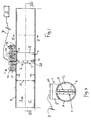
- Figures 1-6 depict a non-limiting embodiment of an assembly comprising a fluid channel C and a flowmeter 1.
- the fluid channel C (for example a fluid line, pipe, conduit) can be configured to conduct a fluid, for example a gas, gas mixture, liquid, liquid mixture, water, steam.
- a fluid for example a gas, gas mixture, liquid, liquid mixture, water, steam.
- the channel C can be arranged to inject fluid into a oil or gas field, however, to skilled person will appreciate the channel C can be used in many other applications.
- the channel C has a substantially circular cross-section having a diameter (width) W.
- the channel can also have different configurations, for example having a rectangular or square cross-section, or a different cross-section, as will be appreciated by the skilled person.
- the flowmeter 1 is configured to measure fluid flow rate of fluid flowing through the channel C during operation.
- the flowmeter 1 comprises at least one vortex shedder 2 (only one being shown in the present drawings) extending in the channel C.
- the assembly has a plurality of spaced-apart vortex shedders 2, to detect flow rates at different locations in the channel C.
- flow rate profiles can be detected with the flowmeter 1, for example to determine or estimate amounts of fluid that are being injected in certain parts (layers) of an oil or gas field.
- each vortex shedder 2 is configured to generate Karman vortices V in fluid flowing through the channel C during operation (see Fig. 3 ).
- a fluid flow direction is indicated in Fig. 3 by arrow Y.
- each vortex shedder 2 comprises a bluff body 2, having two vortex separation edges t, preferably substantially parallel, sharp lateral edges.
- the bluff body 2 can be arranged to have these edges t located at upstream positions with respect to a remaining bluff body part (as in Fig. 3 ), or alternatively at downstream positions (for example, in case the flow direction in Fig. 3 has been reversed).
- the bluff body 2 is rigidly attached to a channel wall 11.
- the flow meter 1 is based on the principle of vortex shedding on an obstacle (bluff body 2) placed in the flowing fluid (see figure 3 ).
- a boundary layer can grow on both sides of the bluff body 2 because of viscosity and can separates at separation points, provided by the edges t.
- the vortices V can separate alternately on both sides of the body 2, with a vortex shedding frequency f K .
- St is the dimensionless Strouhal number
- U is the flow velocity (m/s)
- D b is the diameter/width of the bluff body (m).
- St the Strouhal number St is characteristic for a certain bluff body shape and is constant in a relatively large range of the Reynolds number, so that the relation between flow rate (m/s) and shedding frequency is linear over a wide flow rate range.
- the present embodiment can be used in the case of flow velocities are in the range of 0.5 to 5 m/s (turndown 1:10), and for example can have operation temperatures ranging from 20 to 350 degrees Celsius, at various operating pressures.
- the meter 1 can be configured to be used outside these velocity and temperature ranges, as will be appreciated by the skilled person.
- the boundary layer can be controlled by choosing the shedder body 2 on which the separation points are defined exactly, by introducing sharp edges t on the body 2.
- the bluff body 2 can be made of various materials.
- the bluff body 2 can be made of rigid, corrosive resistant material, particularly a suitable metal, alloy, steel or rigid plastic, reinforced plastic, for example stainless steel, or aluminium (stainless steel is preferred for downhole applications for durability reasons), and/or other suitable materials
- Figures 4-7 show an advantageous embodiment of a bluff body/shedder configuration in more detail.
- the present vortex shedding body 2 provides well-defined separation lines (edges) t, and has a substantially T-shaped cross-section.
- the shedder 2 has been provided with a first part 2A (i.e. the top of the T of the T-shape) and a second part 2B (i.e. the centre line of the T of the T-shape), the first part having the two separation edges t and the second part being a fluid dividing element 2B.
- Both the first and second shedder body parts 2A, 2B can have various configurations.
- the first and second shedder part 2A, 2B are preferably made of the same material, however, this is not necessary.
- the first shedder body part 2A is a rigid, preferably substantially solid part 2A that is rigidly fixed (i.e. substantially unmovably during operation) to the wall 11 of the channel C.
- the first shedder body part 2A comprises a front surface, extending substantially transversally with respect to a longitudinal channel direction (i.e. flow direction Y of fluid flowing through the channel C during use), wherein the lateral sides of the front surface are the vortex separation lines t of the shedder 2.
- the length L1 of the first shedder body part 2A is substantially or nearly equal to the flow channel diameter/width X1 (see Fig. 1 ), so that the walls of the channel C act as end plates for the flow separation edges t (i.e., opposite ends of each flow separation edge t are located at or close to respective channel wall parts of channel wall 11).
- the first part 2A of the bluff body 2 extends from a first inner wall part 11a of the channel C to an opposite second inner wall part 11b of the channel C, as in Fig. 1-2 , and preferably centrally through the channel C.
- a narrow slit can still extend between an end of the bluff body 2 and the channel wall, for example a slit Z having a width of about 1 mm or smaller as has been indicated in Fig 1 .
- the first shedder body part 2A can be firmly fixed at one end (or alternatively at both ends) to a channel wall part (or wall parts), for example by clamping, adhesive, welding, suitable couplings, bolting, detachably, a combination thereof, and/or in a different manner.
- one end of the first shedder body part 2A is attached to a mounting structure 9 that has been firmly joined to the first channel wall part.
- the mounting structure can include a first mounting part 9a to hold the bluff body 2, a second mounting part 9b that is attached to the first part 9a via three first bolts 13a, being spaced-apart from each other in a triangle configuration, and a third mounting part 9c that interconnects the mounting second part 9b to the channel wall 11.
- the channel wall 11 can comprise an opening 12 for introducing the bluff body 2, being held by the first mounting part 9a, into the channel C.
- the mounting structure 9 can be configured to provide a fluid tight sealing of the opening 12 after mounting.
- the length L1 of the respective bluff body part 2A can be significantly smaller than the flow channel diameter/width X1, wherein the bluff body 2 can comprise one or more end plates, extending laterally with respect to the vortex separation edges t, for controlling the boundary layer on the bluff body 2.
- the distance D b between the two vortex separation edges (lines) t measured transversally with respect to a longitudinal channel direction, is larger than a tenth of a width X2 of the fluid channel C, measured in the same direction, for example about a fourth of the width of the fluid channel C, wherein the mentioned distance D b between the two vortex separation edges is preferably smaller than half the width X2 of the channel C.
- the channel C has a circular cross-section
- the last-mentioned channel width X2 is equal to the above-mentioned channel width that is indicated in Fig. 1 with arrow X1.
- a longitudinal cross-section of the first shedder body part 2A is preferably substantially triangular (as in Fig. 3 , 7 ) or truncated triangular, or can have another shape.
- the second shedder part 2B has a panel- like, strip-like or sheet-like configuration, having a substantially rectangular shape (such as in the present embodiment).
- the second shedder part 2B can be dimensioned such in three orthogonal directions, that one orthogonal direction (the thickness K) is significantly smaller (for example by a factor of at least 50) than each of the second and third orthogonal directions (length L2 and width G).
- the second shedder part 2B extends substantially in longitudinal channel direction and has two fluid pressure receiving surfaces, being faced away from each other, that are configured to alternatively receive vortex induced pressure variations during operation (see Fig. 3 ), and to be strained by those pressure variations.
- the pressure variations cause a vibration and/or deformation the second shedder part 2B that is perpendicular to the flow direction Y (in other words: vortex induced deformation and/or vibration of the shedder part 2B will mainly be in lateral directions of that part 2B, and is indicated by double arrow q in Fig. 3 , i.e. vibration and/or deformation that is substantially perpendicular to the pressure receiving surfaces of that shedder part 2B), the deformation and/or vibration leading to surface strain in the second shedder part 2B.
- the second shedder part 2B extends centrally with respect to the first shedder part 2A, perpendicularly with respect to the bluff body surface containing the two separation edges t, and preferably centrally through the channel C after mounting.
- the external contours of the bluff body, including the first and second part 2A, 2B) can be substantially mirror-symmetric with respect to a longitudinal central mirror plan, as in the present embodiment.
- one transversal side (a lower side of that part in Fig. 5A ) of the second shedder part 2B extends flush with the respective side of the first shedder part 2A (see Fig. 5 ).
- the other transversal side of the first shedder part 2B is spaced-apart from the mounting structure 9 (see Fig. 5 ), the distance there-between being indicated by an arrow H in Fig. 5 .
- the second shedder part 2B is a pressure variation receiving part 2B, or straining part, that is configured to receive vortex induced pressure variations during operation.
- the Karman vortices can induce strain variations in the second shedder part 2B (indicated by the arrow q in Fig. 3 ), and more particularly in surface parts thereof (i.e. vortex induced pressure variations during operation lead to surface strain in/of the second shedder part 2B).
- the second shedder part 2B can be slightly elastically deformable during operation, such that this shedder part 2B performs small oscillations q during operation due to receiving vortex related pressure variations, the small oscillations q leading to a varying straining of the two lateral (pressure receiving) surfaces of the second shedder part 2B. It has been found that these strain variations are particularly relatively high at a region that abuts the first shedder part 2A (i.e a junction with the first shedder part 2A).
- the pressure variation receiving part (i.e. second part) 2B of the shedder 2 comprises two transversal sides that are spaced-apart from opposite longitudinal flow restriction parts (that include a channel wall part for one transversal shedder side, and a mounting structure part for the other transversal shedder side, in the present embodiment).
- a distance Z between the (in the drawing) lower transversal side of the rectangular vortex shedder part 2B and the channel wall 11 is preferably in the range of about 0.1-10 mm, particularly about 1-2 mm, and the width H of the slit between the (in Fig.
- upper transversal side of the rectangular vortex shedder part 2B and a surface of the first mounting part 9a is also preferably in the range of about 0.1-10 mm, particularly about 1-2 mm. Therefore, the transversal sides of the second shedder part 2B are free from opposite flow restricting surfaces, such that vortex induces pressure variations can lead to surface strain variations in and/or oscillations of the second shedder part 2B. Particularly, the vortex induced pressure variations can induce vibration and/or deformation of the vortex shedder, which vibration and/or deformation can cause the surface strain.
- the length L2 of the second shedder part 2B (measured in parallel direction with respect to the separation lines t) is slightly smaller than the length L1 of the first shedder part 2A, the difference in length being for example in the range of about 0.1-20 mm, particularly in the range of about 1-2mm (see Fig. 5 )
- the length L2 of the second shedder part 2B is preferably larger than a width G of an external section (tail section) of that part 2B, the width G being measured in longitudinal channel direction (see Fig. 5 ; herein, the width G of the second shedder part 2B is the width of the section of that part that extends externally from the first shedder part, and serves as a fluid pressure variation receiving section of the shedder).
- the length L2 of the second part 2B can be in the range of about 1.5-2 times the mentioned width G of that part 2B. Good results have been found in the case that L2 is in the range of 1.7-1.9 times G, particularly length L2 equals the width G multiplied by 1.8.
- a thickness K of the second shedder body part 2B is smaller than about 10 mm, preferably smaller than about 5 mm and particularly in the range of about 1-2 mm (see Fig. 7 ).
- first and second shedder parts 2A, 2B can be joined to each other in various ways.
- first and second shedder parts can be made in one piece.
- first and second shedder parts 2A, 2B can be interconnected with adhesive, welding, bolting (as in the Fig. 1-7 embodiment, with bolts 6), clamping, force closure fixation, form closure fixation, a combination thereof and/or in a different manner.
- the second shedder part 2B comprises an internal section that extends in the first shedder part 2A to be held thereby, and the above-described external section (having the mentioned width G) that extends outside the first shedder part 2A to perceive vortex induced pressure variations.
- the mentioned external (tail) section of the second shedder part 2B is substantially uninterrupted, providing substantially uninterrupted (continuous) pressure receiving surfaces.
- first and second shedder parts 2A, 2B are configured such that relatively vortex pressure variations can induce relatively large strain variations into a certain area of the shedder (for example the external section of the second shedder part 2B that abuts the first shedder part 2A).
- each vortex shedder 2 is provided with a first fiber Bragg grating FBG of a fiber Bragg grating sensor 3, 7, FBG.
- a Karman vortex frequency f K of the vortices V generated by the vortex shedder 2 is detectable utilizing a fiber Bragg grating sensor signal relating to the respective first fiber Bragg grating FBG of that vortex shedder 2.
- the first fiber Bragg rating FBG is attached to the section of shedder 2 that experiences relatively large surface strain variations due to vortex pressure variations induced vibration/deformation during operation, and is configured to detect those strain variations.
- the fiber Bragg grating FBG of the respective vortex shedder 2 is arranged to perceive the mentioned pressure variations, particularly via pressure variation induced strain variations of the pressure variation receiving part 2B of the shedder 2, and to vary the respective fiber Bragg grating sensor signal as a result of perceiving the pressure variations.
- the fiber Bragg grating FBG is mounted close to, or extends in, abuts, or is embedded in, a pressure receiving surface of the second shedder part 2B, to be sensitive to the mentioned surface strain that is caused by the deformation/vibration of that shedder part 2B during operation.
- the first fiber Bragg grating FBG is spaced-apart from a vortex separation surface (which surface contains the two vortex separation lines t) of the respective vortex shedder 2. Also, preferably, the location of the first fiber Bragg grating FBG is spaced-apart from the two transversal sides of the second shedder part 2B.
- a longitudinal direction of the first fiber Bragg grating FBG preferably encloses an angle smaller than 90° with a fluid flow direction during operation, for example an angle smaller than 30° and preferably an angle smaller than 5 0 .
- the angle between the longitudinal direction of the first fiber Bragg grating FBG and the fluid flow direction Y is about 0 0 .
- the pressure variation receiving part/second shedder part 2B integrally comprises a curved fiber part 8, extending at least partly along a curved path and containing the first fiber Bragg grating FBG (see Fig. 4-5 ).
- a first section 8a of the curved fiber part 8 preferably extends a short distance from a free shedder edge E that is faced away from a vortex shedding surface of the vortex shedder 2, in a substantially orthogonal direction with respect to a longitudinal channel direction (see Fig. 5 ).
- a second section 8b of the fiber part 8 is preferably located near a vortex shedding surface of the vortex shedder 2 and extends substantially parallel to the longitudinal channel direction. In the present embodiment, this second fiber section 8b comprises the first fiber Bragg grating FBG.
- the curved path of the fiber part comprises a first bend A1 to lead the fiber from an entry location at the first shedder part 2A towards the free shedder edge E, and a subsequent second bend A2 (having a bend direction that is opposite to the bend direction of the first bend) to lead the fiber from the free shedder edge E back to the first shedder part 2A to a Bragg grating location that is spaced-apart from the entry location.
- the fiber can be bended further (for example to make a substantially full loop along and/or through the vortex shedder 2), and can be guided back towards the channel wall 11 and through the holding structure 9, for example to be led to another vortex shedder 2 to provide another first Bragg grating in/at that other shedder 2.
- fiber the entry location (point) can also provide a fiber exit location.
- the mounting structure 9 comprises a through-hole 15 (see fig. 5 ) to pass the fiber 7 from an area outside the channel C to the vortex shedder 2.
- the first shedder part 2A can comprise a similar aperture to receive part of the fiber 7.
- the second shedder part 2B can comprise a curved groove 5 or aperture to hold the curve fiber part 8 containing the first fiber Bragg grating FBG.
- the through-hole 15 can also be used to guide the fiber 7 from the vortex shedder 2 again out of the channel, through the channel wall 11, to another location, for example to another vortex shedder (not shown).
- the fiber receiving groove 5 of the shedder 2 can have a depth smaller than the thickness K of the second shedder part 2B, for example a depth smaller than 1 mm, for example about 0.4 mm.
- depth of the fiber receiving groove 5 can be smaller than half the thickness K of the second shedder part 2B to locate the grating FBG close to and/or in a lateral surface of that part 2B.
- the curved fiber part 8 is substantially embedded in the respective shedder part 2B.
- the optical fiber part 8 having the Bragg grating FBG can be attached to the respective groove 5, using a suitable adhesive, for example a thermally curable resin, epoxy, or other type of adhesive.
- the fiber receiving groove 5 is configured to hold the respective fiber part substantially snuggly.
- a width of the groove 5 can be about 1 mm.
- the assembly can be of a modular configuration, wherein the assembly can include a plurality of vortex shedders 2, each shedder 2 preferably being provided with a mentioned first fiber Bragg grating FBG of the fiber Bragg grating sensor.
- a single fiber 7 can simply be provided with all of the first fiber Bragg gratings FBG of the various shedders 2, wherein the fiber 7 can extend from one shedder to the other to transmit the sensors signals.
- each fiber Bragg grating FBG is configured to substantially reflect one specific wavelength of an optical signal, being transmitted towards the grating FGB through the fiber 7, and to substantially transmit all other wavelengths.
- the wavelength of the reflected light depends on the variation of the refractive index in the grating FBG.
- the amplitude of the sensor signal is a measure of the amount of strain experienced by the grating FBG during operation.
- the reflected wavelength is used as a measure of the flow velocity, wherein the changes of that wavelength are being detected (i.e. reflected sensor signal amplitude changes), which can be achieved in a relatively simple manner, to determine the above-mentioned Karman frequency f K .
- the fiber 7 can be a standard optical fiber with one or more Bragg gratings FBG, having a minimum bending radius of about 2 to 3 cm and a grating length N (see Fig. 5 ), for each Bragg gratings FBG, of approximately 2 cm.
- the fiber 7 can also have a smaller bending radius and/or a shorter grating.
- the length N of the first fiber Bragg grating can be about 1 cm.
- the first grating FBG is principally used to detect a varying strain in/of the vortex shedder 2, wherein a resulting change in the respective sensor signal can be processed to determine the flow velocity U of the fluid.
- a preferred location for the first grating FBG is on the beginning of the tail part 2B of the shedder 2, immediately behind the (truncated triangle) second shedder part 2A (see figures 5 , 7 ) since it has been found that during operation, the Karman vortex induced strain variations will be largest on this section of the tail shedder part 2B.
- the whole first grating FBG can be substantially homogeneously strained during operation, which is achieved by positioning the grating FBG substantially parallel to the longitudinal channel direction.
- the strain does not have to be wholly constant over the whole fiber to obtain accurate measurement results. This is because frequency (i.e. the variation of the amplitude, and not the amplitude as such) is the measured parameter, so that amplitude variations of a detected reflected signal do not effect the outcome of the flow measurement.
- frequency i.e. the variation of the amplitude, and not the amplitude as such
- the sensor amplitude signal, of the reflected signal can have a relatively large error due to inhomogeneous straining of the grating.
- the present assembly can include a suitable sensor system 3 (for example comprising one or more suitable processors and/or analyzers), for example a commercially available system of the company Deminsys Commercial, the sensor system being optically coupled to the optical fiber 7.
- the sensor system 3 can be configured to generate and transmit an optical signal into the fiber 7, the signal having a wavelength (i.e. the above-mentioned Bragg wavelength) to be at least partly reflected by the first fiber Bragg grating FBG in the case that the grating is being subjected to a predetermined amount of strain, for example no strain.
- the optical signal can be multiplexed with different signal parts having these different Bragg wavelengths ⁇ b , such that the different gratings FBG can be used independently from each other and at the same time, by the sensor system 3.
- the sensor system 3 can be configured to detect the optical signal that is reflected by each first fiber Bragg grating FBG of the vortex shedder(s) 2, and to process the detected optical signal(s) to determine the fluid flow rate from the variations of the detected signal(s).
- the fluid flow will induce a vortex shedding at the shedder 2, which will cause pressure fluctuations on the tail part 2B of the bluff body 2. Because of the pressure fluctuations, the tail will be induced to oscillate, which will lead to fluctuating surface strain of the tail part 2B and thus strain fluctuations of the integral first fiber Bragg grating FBG (being preferably mounted on or close to the respective surface of the second shedder part 2B, to measure that surface strain). The surface strain as result of these oscillations will be measured.
- the sensor system 3 transmitting an optical signal having the Bragg wavelength FBG of the first fiber Bragg grating of the vortex shedder 2 into the fiber 7, and detecting the respective optical signal that is reflected by the first fiber Bragg grating FBG.
- the detected optical signal is then processed to detect variations of the detected signal (the variations being the result of the varying strain that is being experienced by the grating FBG), to determine the fluid flow rate from those variations using above equation 1.
- a single FBG sensor is applied to detect the flow rate at a certain location in the fluid channel C, wherein -for example- no complex cross-correlation of different grating sensor signals has to be carried out.
- Figure 8 shows a graph of measured shedding frequency f K with respect to flow speed, of experiments performed with the present embodiment.
- a flow speed U flow of fluid flowing through the channel C has been set to 11 different predetermined values (from 0 m/s to 5.5 m/s with 0.25 m/s steps) and the resulting FBG sensor signal was being processed to detect the Karman frequency.
- three different test runs all provided the same linear graph of detected frequency f K versus the flow speed U flow . Reliable data can be obtained for low flow rates (0.5 m/s in the present example) as well as high flow rates (5.5. m/s in the present example).
- the present application provides a fiber optic vortex flow meter 1, wherein, in an embodiment, strain resulting from vortex shedding can be measured using a Fiber Bragg Grating (FBG) sensor.
- FBG Fiber Bragg Grating
- This sensor can use a relatively small section of a standard optical fiber 7, so that no downhole electronics are necessary, since the sensor signal can be fed directly to the surface.
- the advantages of a fiber optic flow meter are that the meter is intrinsically safe and immune to electromagnetic interference.
- the bluff body 2 can be substantially T-shaped, comprising a truncated triangle part 2A with a long tail part 2B attached to it.
- the tail part 2B of this body is preferably made as thin as possible, to increase its deformation and therefore the strain measured with the sensor.
- the flow meter 1 can detect single phase flows (liquid or gas), for example water, steam, or other fluids.
- the present embodiment can provide an optimal bluff body design with regard to the linearity of the measurement and to the signal quality, wherein the FBG can provide the sensor signal with detectable strain oscillation information over relatively large flow rate velocity ranges.
- the sensor can provide accurate flow rate measurements, and is very sensitive to flow rate changes.
- the substantially T-shaped body such as the present embodiment, is an optimum bluff body configuration to generate strain.
- the deflection of the rectangular plate-like section of the bluff body 2B can be relatively high.
- the T-shaped body is also the only shape that can be used to connect a series of flow meters with one fiber. Further it as been found that this shape can provide a very good signal-to-noise ratio of the sensor signal during operation.
- the fibre part that has been joined with the vortex shedder 2 can comprise other fiber Bragg gratings, for example to detect temperature.
- the vortex shedder 2 can be provided with a second fiber Bragg grating FBG2 of the fiber Bragg grating sensor system 3, 7, the second fiber Bragg grating FBG2 being configured to vary a respective fiber Bragg grating sensor signal as a result of perceiving temperature variations.
- a longitudinal direction of the second fiber Bragg grating FBG preferably extends substantially perpendicular with respect to a longitudinal channel direction.
- the extra -second- grating FBG2 can be located a shedder location that is not substantially affected by the Karman vortices V.
- two possible locations for a temperature grating are indicated by arrows FBG2.
- a second fiber grating FBG2 can be provided in a mentioned first section 8a of the curved fiber part 8, or near the entry (and optionally also exit) point near the channel wall 11.
- the assembly can be provided with another optical fiber, that does not include a mentioned first grating FBG, but does include a second grating and holds the second grating in the fluid flow to detect fluid temperature.
- the present invention can be used in mass flow determinations, for example following the teachings of the publication " A study of mass flow rate measurement based on the vortex shedding principle” H. Zhang et al., Flow Measurement and Instrumentation 17 (1), 2006 , utilizing measurement results of a pressure sensor (not shown in the present application) located upstream with respect to the shedder 2 (and being spaced-apart from the shedder 2).
- the shedder/bluff body 2 can be dimensioned in various ways and can have various shapes.
- the first shedder part can have a substantially triangle-shaped cross-section, truncated triangle-shaped cross-section of a different cross-section.
- the first part 2A of the bluff body 2 can be attached with only one end to a channel wall 11, or with opposite ends if desired.
Landscapes
- Physics & Mathematics (AREA)
- Fluid Mechanics (AREA)
- General Physics & Mathematics (AREA)
- Measuring Volume Flow (AREA)
- Measuring Fluid Pressure (AREA)
- Indicating Or Recording The Presence, Absence, Or Direction Of Movement (AREA)
- Details Of Flowmeters (AREA)
Abstract
An assembly comprising a fluid channel and a flowmeter, the flowmeter (1) comprising at least one vortex shedder (2) extending in the channel (C), each vortex shedder (2) being configured to generate Karman vortices (V) in fluid flowing through the channel (C) during operation, wherein each vortex shedder (2) is provided with a first fiber Bragg grating (FBG) of a fiber Bragg grating sensor (3, 7, FBG), wherein a Karman vortex frequency (fK) of the vortices (V) generated by the vortex shedder (2) is detectable utilizing a fiber Bragg grating (FBG) sensor signal relating to the respective first fiber Bragg grating (FBG) of that vortex shedder (2).
Description
- The invention relates to an assembly comprising a fluid channel and a flowmeter, and a method to measure a fluid flow rate.
- In oil/gas wells, water or steam is often injected into the oil/gas field to increase production. It is desired to provide information about the flow conditions in the water/steam injection lines available. However, there are only a limited amount of flow meters available for downhole applications which are very expensive, bulky and complex, see for example the system described in
US patent nr 6,691,584 B2 . - Besides,
JP200387451 - The present invention aims to solve these problems. Particularly, the present invention aims to provide an assembly and method, wherein fluid flow rate can be measured accurately, preferably over a relatively broad range, using relatively inexpensive, compact and durable means.
- To this aim, according to an embodiment of the invention, the assembly is characterised by the features of
claim 1. - Advantageously, the flowmeter comprising at least one vortex shedder extending in the channel, each vortex shedder being configured to generate Karman vortices in fluid flowing through the channel during operation, wherein each vortex shedder is provided with a first fiber Bragg grating (FBG) of a fiber Bragg grating sensor, wherein a Karman vortex frequency of the vortices generated by the vortex shedder is detectable utilizing a fiber Bragg grating sensor signal relating to the respective first fiber Bragg grating of that vortex shedder. Also, for example, by multiplexing of several FBG flow sensors, a sensor array using a single lead fiber can be provided.
- It has been found that the present assembly can provide highly accurate flow rate measurement results that reproduce very well. Also, the flowmeter of the present assembly (particularly the vortex shedder and respective fiber Bragg grating part) can be made compact and durable, whereas the flowmeter can also be provided by relatively inexpensive means.
- A basic idea behind the present invention is, that the fiber Brag grating part of the flowmeter can simply be integrated with the Karman vortex shedder. The flowmeter can still accurately determine fluid flow speed, by deducing the Karman vortex frequency from the sensor signal, relating to the respective fiber Bragg grating. The Karman frequency provides a very reliable measure for the flow speed, since that frequency and the fluid flow speed are generally linearly dependent on one another, particularly in certain fluid rate ranges that are common in downhole applications. Besides, the FBG sensor signal can be processed using relatively simple processing means, to find the Karman frequency as detected by a single respective FBG.
- The use of fiber Bragg gratings in water flowmeters as such is known from the publication "A water flowmeter using dual fiber Bragg grating sensors and cross-correlation technique", Shoichi Takashima et al. Sensors and Acuators A 116 2004 pp.66 (Elsevier). However, this publication leads away from the present invention by teaching to apply at least two separate cantilever FBG sensors located downstream of a Bluff body, wherein respective sensor signals are required to be cross-correlated to detect a time delay and wherein the flow velocity follows from the distance between the two FBG sensors and the time delay. This known systems is expensive, complex, prone to mechanical malfunctions, takes in much space and thus also difficult to mount. Besides, this system can only detect flow rates of fluid flowing in one direction.
- Besides, according to an embodiment, there is provided a flowmeter of the assembly according the invention, the flowmeter being specifically adapted to measure a fluid flow rate in a fluid channel by determining the Karman vortex frequency of vortices shed by the at least one vortex shedder during operation, utilizing at least one respective fiber Bragg grating sensor signal relating to the respective first fiber Bragg grating of that vortex shedder. The flowmeter is well adapted to the extreme conditions (high temperature and pressure) of downhole applications, since the Bragg grating sensor can avoid the use of electronics downhole.
- Also, there is provided a method for measuring a fluid flow rate, of fluid flowing through a channel. The method can, for example, utilise a flowmeter according to the invention, and particularly comprises:
- providing at least one vortex shedder in the channel, each vortex shedder shedding Karman vortices in the fluid flowing through the channel;
- providing the vortex shedder with a fiber having at least one first fiber Bragg grating, the grating being configured to reflect an optical signal of a certain wavelength depending on an amount of strain to which the grating is being subjected, wherein fluid pressure variations that result from the Karman vortices lead to a varying strain being subjected to the respective fiber Bragg grating;
- transmitting an optical signal into the fiber, the signal having a wavelength to be at least partly reflected by the first fiber Bragg grating in the case that the grating is being subjected to a predetermined amount of strain, for example no strain;
- detecting the optical signal that is reflected by the first fiber Bragg grating of the vortex shedder; and
- processing the detected optical signal to determine the fluid flow rate from the variations of the detected signal.
- Preferably, the method includes the measuring of surface strain variations of a surface part of the vortex shedder, utilizing the fiber Bragg grating.
- Further advantageous embodiments of the invention are described in the dependent claims. These and other aspects of the invention will be apparent from and elucidated with reference to non-limiting embodiments described hereafter, shown in the drawings.
-
Figure 1 depicts a longitudinal cross-section of an embodiment of the invention; -
Figure 2 depicts a cross-section over line II-II ofFig. 1 ; -
Figure 3 shows a longitudinal, schematic, cross-section over line III-III offig. 1 ; -
Figure 4 is a perspective view of a vortex shedder of the embodiment ofFig. 1 ; -
Figure 5 is a longitudinal cross-section of the shedder shown inFig. 4 ; -
Figure 6 is a front view of the shedder ofFig. 4 ; -
Figure 7 is a cross-section over line VII-VII ofFig. 6 ; and -
Figure 8 shows a graph of measured shedding frequency with respect to flow speed, of an example. - Similar or corresponding features are denoted by similar or corresponding reference signs in the present application.
-
Figures 1-6 depict a non-limiting embodiment of an assembly comprising a fluid channel C and aflowmeter 1. - The fluid channel C (for example a fluid line, pipe, conduit) can be configured to conduct a fluid, for example a gas, gas mixture, liquid, liquid mixture, water, steam. In a particular embodiment, the channel C can be arranged to inject fluid into a oil or gas field, however, to skilled person will appreciate the channel C can be used in many other applications. In the present embodiment, the channel C has a substantially circular cross-section having a diameter (width) W. The channel can also have different configurations, for example having a rectangular or square cross-section, or a different cross-section, as will be appreciated by the skilled person.
- The
flowmeter 1 is configured to measure fluid flow rate of fluid flowing through the channel C during operation. To this aim, theflowmeter 1 comprises at least one vortex shedder 2 (only one being shown in the present drawings) extending in the channel C. In a further embodiment the assembly has a plurality of spaced-apart vortex shedders 2, to detect flow rates at different locations in the channel C. In that case, flow rate profiles can be detected with theflowmeter 1, for example to determine or estimate amounts of fluid that are being injected in certain parts (layers) of an oil or gas field. - Each
vortex shedder 2 is configured to generate Karman vortices V in fluid flowing through the channel C during operation (seeFig. 3 ). A fluid flow direction is indicated inFig. 3 by arrow Y. Particularly, eachvortex shedder 2 comprises abluff body 2, having two vortex separation edges t, preferably substantially parallel, sharp lateral edges. Thebluff body 2 can be arranged to have these edges t located at upstream positions with respect to a remaining bluff body part (as inFig. 3 ), or alternatively at downstream positions (for example, in case the flow direction inFig. 3 has been reversed). In the present embodiment, thebluff body 2 is rigidly attached to a channel wall 11. - Particularly, the
flow meter 1 is based on the principle of vortex shedding on an obstacle (bluff body 2) placed in the flowing fluid (seefigure 3 ). A boundary layer can grow on both sides of thebluff body 2 because of viscosity and can separates at separation points, provided by the edges t. During operation, the vortices V can separate alternately on both sides of thebody 2, with a vortex shedding frequency fK. As is known from the prior art, the vortex shedding frequency fK is proportional to the flow velocity U, according to the following equation 1:
wherein St is the dimensionless Strouhal number, U is the flow velocity (m/s) and Db is the diameter/width of the bluff body (m). As is commonly known, the Strouhal number St is characteristic for a certain bluff body shape and is constant in a relatively large range of the Reynolds number, so that the relation between flow rate (m/s) and shedding frequency is linear over a wide flow rate range. For example, the present embodiment can be used in the case of flow velocities are in the range of 0.5 to 5 m/s (turndown 1:10), and for example can have operation temperatures ranging from 20 to 350 degrees Celsius, at various operating pressures. Also, themeter 1 can be configured to be used outside these velocity and temperature ranges, as will be appreciated by the skilled person. The boundary layer can be controlled by choosing theshedder body 2 on which the separation points are defined exactly, by introducing sharp edges t on thebody 2. - The
bluff body 2 can be made of various materials. For example, thebluff body 2 can be made of rigid, corrosive resistant material, particularly a suitable metal, alloy, steel or rigid plastic, reinforced plastic, for example stainless steel, or aluminium (stainless steel is preferred for downhole applications for durability reasons), and/or other suitable materials -
Figures 4-7 show an advantageous embodiment of a bluff body/shedder configuration in more detail. To have a linear relation between the flow velocity and the vortex shedding, the presentvortex shedding body 2 provides well-defined separation lines (edges) t, and has a substantially T-shaped cross-section. To this aim, particularly, theshedder 2 has been provided with a first part 2A (i.e. the top of the T of the T-shape) and asecond part 2B (i.e. the centre line of the T of the T-shape), the first part having the two separation edges t and the second part being afluid dividing element 2B. - Both the first and second
shedder body parts 2A, 2B can have various configurations. The first andsecond shedder part 2A, 2B are preferably made of the same material, however, this is not necessary. - Advantageously, the first shedder body part 2A is a rigid, preferably substantially solid part 2A that is rigidly fixed (i.e. substantially unmovably during operation) to the wall 11 of the channel C. The first shedder body part 2A comprises a front surface, extending substantially transversally with respect to a longitudinal channel direction (i.e. flow direction Y of fluid flowing through the channel C during use), wherein the lateral sides of the front surface are the vortex separation lines t of the
shedder 2. - In the present embodiment, the length L1 of the first shedder body part 2A is substantially or nearly equal to the flow channel diameter/width X1 (see
Fig. 1 ), so that the walls of the channel C act as end plates for the flow separation edges t (i.e., opposite ends of each flow separation edge t are located at or close to respective channel wall parts of channel wall 11). Thus, the first part 2A of thebluff body 2 extends from a first inner wall part 11a of the channel C to an opposite second inner wall part 11b of the channel C, as inFig. 1-2 , and preferably centrally through the channel C. Herein, for example, a narrow slit can still extend between an end of thebluff body 2 and the channel wall, for example a slit Z having a width of about 1 mm or smaller as has been indicated inFig 1 . - For example, in a durable configuration, the first shedder body part 2A can be firmly fixed at one end (or alternatively at both ends) to a channel wall part (or wall parts), for example by clamping, adhesive, welding, suitable couplings, bolting, detachably, a combination thereof, and/or in a different manner. In the present embodiment, one end of the first shedder body part 2A is attached to a mounting structure 9 that has been firmly joined to the first channel wall part. For example, the mounting structure can include a first mounting part 9a to hold the
bluff body 2, a second mounting part 9b that is attached to the first part 9a via threefirst bolts 13a, being spaced-apart from each other in a triangle configuration, and a third mounting part 9c that interconnects the mounting second part 9b to the channel wall 11. Besides, the channel wall 11 can comprise an opening 12 for introducing thebluff body 2, being held by the first mounting part 9a, into the channel C. The mounting structure 9 can be configured to provide a fluid tight sealing of the opening 12 after mounting. - In another embodiment, the length L1 of the respective bluff body part 2A, can be significantly smaller than the flow channel diameter/width X1, wherein the
bluff body 2 can comprise one or more end plates, extending laterally with respect to the vortex separation edges t, for controlling the boundary layer on thebluff body 2. - In a further embodiment (see
Fig. 3 ), the distance Db between the two vortex separation edges (lines) t, measured transversally with respect to a longitudinal channel direction, is larger than a tenth of a width X2 of the fluid channel C, measured in the same direction, for example about a fourth of the width of the fluid channel C, wherein the mentioned distance Db between the two vortex separation edges is preferably smaller than half the width X2 of the channel C. Since in the present embodiment, the channel C has a circular cross-section, the last-mentioned channel width X2 is equal to the above-mentioned channel width that is indicated inFig. 1 with arrow X1. - A longitudinal cross-section of the first shedder body part 2A is preferably substantially triangular (as in
Fig. 3 ,7 ) or truncated triangular, or can have another shape. - Preferably, the
second shedder part 2B has a panel- like, strip-like or sheet-like configuration, having a substantially rectangular shape (such as in the present embodiment). For example thesecond shedder part 2B can be dimensioned such in three orthogonal directions, that one orthogonal direction (the thickness K) is significantly smaller (for example by a factor of at least 50) than each of the second and third orthogonal directions (length L2 and width G). - Also, preferably, the
second shedder part 2B extends substantially in longitudinal channel direction and has two fluid pressure receiving surfaces, being faced away from each other, that are configured to alternatively receive vortex induced pressure variations during operation (seeFig. 3 ), and to be strained by those pressure variations. In the present embodiment, particularly, the pressure variations cause a vibration and/or deformation thesecond shedder part 2B that is perpendicular to the flow direction Y (in other words: vortex induced deformation and/or vibration of theshedder part 2B will mainly be in lateral directions of thatpart 2B, and is indicated by double arrow q inFig. 3 , i.e. vibration and/or deformation that is substantially perpendicular to the pressure receiving surfaces of thatshedder part 2B), the deformation and/or vibration leading to surface strain in thesecond shedder part 2B. - In the present embodiment, the
second shedder part 2B extends centrally with respect to the first shedder part 2A, perpendicularly with respect to the bluff body surface containing the two separation edges t, and preferably centrally through the channel C after mounting. For example, the external contours of the bluff body, including the first andsecond part 2A, 2B) can be substantially mirror-symmetric with respect to a longitudinal central mirror plan, as in the present embodiment. - In the present embodiment, one transversal side (a lower side of that part in
Fig. 5A ) of thesecond shedder part 2B extends flush with the respective side of the first shedder part 2A (seeFig. 5 ). The other transversal side of thefirst shedder part 2B, however, is spaced-apart from the mounting structure 9 (seeFig. 5 ), the distance there-between being indicated by an arrow H inFig. 5 . - The
second shedder part 2B is a pressurevariation receiving part 2B, or straining part, that is configured to receive vortex induced pressure variations during operation. Particularly, the Karman vortices can induce strain variations in thesecond shedder part 2B (indicated by the arrow q inFig. 3 ), and more particularly in surface parts thereof (i.e. vortex induced pressure variations during operation lead to surface strain in/of thesecond shedder part 2B). For example, thesecond shedder part 2B can be slightly elastically deformable during operation, such that thisshedder part 2B performs small oscillations q during operation due to receiving vortex related pressure variations, the small oscillations q leading to a varying straining of the two lateral (pressure receiving) surfaces of thesecond shedder part 2B. It has been found that these strain variations are particularly relatively high at a region that abuts the first shedder part 2A (i.e a junction with the first shedder part 2A). - In a further embodiment, the pressure variation receiving part (i.e. second part) 2B of the
shedder 2 comprises two transversal sides that are spaced-apart from opposite longitudinal flow restriction parts (that include a channel wall part for one transversal shedder side, and a mounting structure part for the other transversal shedder side, in the present embodiment). For example, inFig. 1 , a distance Z between the (in the drawing) lower transversal side of the rectangularvortex shedder part 2B and the channel wall 11 is preferably in the range of about 0.1-10 mm, particularly about 1-2 mm, and the width H of the slit between the (inFig. 1 ) upper transversal side of the rectangularvortex shedder part 2B and a surface of the first mounting part 9a is also preferably in the range of about 0.1-10 mm, particularly about 1-2 mm. Therefore, the transversal sides of thesecond shedder part 2B are free from opposite flow restricting surfaces, such that vortex induces pressure variations can lead to surface strain variations in and/or oscillations of thesecond shedder part 2B. Particularly, the vortex induced pressure variations can induce vibration and/or deformation of the vortex shedder, which vibration and/or deformation can cause the surface strain. - Thus, preferably, the length L2 of the
second shedder part 2B (measured in parallel direction with respect to the separation lines t) is slightly smaller than the length L1 of the first shedder part 2A, the difference in length being for example in the range of about 0.1-20 mm, particularly in the range of about 1-2mm (seeFig. 5 ) - The length L2 of the
second shedder part 2B is preferably larger than a width G of an external section (tail section) of thatpart 2B, the width G being measured in longitudinal channel direction (seeFig. 5 ; herein, the width G of thesecond shedder part 2B is the width of the section of that part that extends externally from the first shedder part, and serves as a fluid pressure variation receiving section of the shedder). For example, the length L2 of thesecond part 2B can be in the range of about 1.5-2 times the mentioned width G of thatpart 2B. Good results have been found in the case that L2 is in the range of 1.7-1.9 times G, particularly length L2 equals the width G multiplied by 1.8. - Also, it has been found that good results can be obtained in the case that a thickness K of the second
shedder body part 2B (measured in its transversal direction) is smaller than about 10 mm, preferably smaller than about 5 mm and particularly in the range of about 1-2 mm (seeFig. 7 ). - The first and
second shedder parts 2A, 2B can be joined to each other in various ways. For example, the first and second shedder parts can be made in one piece. Also, first andsecond shedder parts 2A, 2B can be interconnected with adhesive, welding, bolting (as in theFig. 1-7 embodiment, with bolts 6), clamping, force closure fixation, form closure fixation, a combination thereof and/or in a different manner. In the present embodiment, thesecond shedder part 2B comprises an internal section that extends in the first shedder part 2A to be held thereby, and the above-described external section (having the mentioned width G) that extends outside the first shedder part 2A to perceive vortex induced pressure variations. Preferably, as follows from the drawing, the mentioned external (tail) section of thesecond shedder part 2B is substantially uninterrupted, providing substantially uninterrupted (continuous) pressure receiving surfaces. - Preferably, the first and
second shedder parts 2A, 2B are configured such that relatively vortex pressure variations can induce relatively large strain variations into a certain area of the shedder (for example the external section of thesecond shedder part 2B that abuts the first shedder part 2A). - Also, each
vortex shedder 2 is provided with a first fiber Bragg grating FBG of a fiberBragg grating sensor vortex shedder 2 is detectable utilizing a fiber Bragg grating sensor signal relating to the respective first fiber Bragg grating FBG of thatvortex shedder 2. Preferably, the first fiber Bragg rating FBG is attached to the section ofshedder 2 that experiences relatively large surface strain variations due to vortex pressure variations induced vibration/deformation during operation, and is configured to detect those strain variations. - Also, in a further embodiment the fiber Bragg grating FBG of the
respective vortex shedder 2 is arranged to perceive the mentioned pressure variations, particularly via pressure variation induced strain variations of the pressurevariation receiving part 2B of theshedder 2, and to vary the respective fiber Bragg grating sensor signal as a result of perceiving the pressure variations. Preferably, the fiber Bragg grating FBG is mounted close to, or extends in, abuts, or is embedded in, a pressure receiving surface of thesecond shedder part 2B, to be sensitive to the mentioned surface strain that is caused by the deformation/vibration of thatshedder part 2B during operation. - Advantageously, the first fiber Bragg grating FBG is spaced-apart from a vortex separation surface (which surface contains the two vortex separation lines t) of the
respective vortex shedder 2. Also, preferably, the location of the first fiber Bragg grating FBG is spaced-apart from the two transversal sides of thesecond shedder part 2B. - Besides (a follows from
Fig. 5 ), a longitudinal direction of the first fiber Bragg grating FBG preferably encloses an angle smaller than 90° with a fluid flow direction during operation, for example an angle smaller than 30° and preferably an angle smaller than 50. In the present embodiment, the angle between the longitudinal direction of the first fiber Bragg grating FBG and the fluid flow direction Y is about 00. - Particularly, the pressure variation receiving part/
second shedder part 2B integrally comprises a curved fiber part 8, extending at least partly along a curved path and containing the first fiber Bragg grating FBG (seeFig. 4-5 ). A first section 8a of the curved fiber part 8 preferably extends a short distance from a free shedder edge E that is faced away from a vortex shedding surface of thevortex shedder 2, in a substantially orthogonal direction with respect to a longitudinal channel direction (seeFig. 5 ). A second section 8b of the fiber part 8 is preferably located near a vortex shedding surface of thevortex shedder 2 and extends substantially parallel to the longitudinal channel direction. In the present embodiment, this second fiber section 8b comprises the first fiber Bragg grating FBG. Particularly, the curved path of the fiber part, being provided on/in theshedder 2, comprises a first bend A1 to lead the fiber from an entry location at the first shedder part 2A towards the free shedder edge E, and a subsequent second bend A2 (having a bend direction that is opposite to the bend direction of the first bend) to lead the fiber from the free shedder edge E back to the first shedder part 2A to a Bragg grating location that is spaced-apart from the entry location. - In a further embodiment (not shown) the fiber can be bended further (for example to make a substantially full loop along and/or through the vortex shedder 2), and can be guided back towards the channel wall 11 and through the holding structure 9, for example to be led to another
vortex shedder 2 to provide another first Bragg grating in/at thatother shedder 2. In that case, fiber the entry location (point) can also provide a fiber exit location. - Particularly, in the present embodiment, the mounting structure 9 comprises a through-hole 15 (see
fig. 5 ) to pass thefiber 7 from an area outside the channel C to thevortex shedder 2. The first shedder part 2A can comprise a similar aperture to receive part of thefiber 7. Thesecond shedder part 2B can comprise acurved groove 5 or aperture to hold the curve fiber part 8 containing the first fiber Bragg grating FBG. I a further embodiment, the through-hole 15 can also be used to guide thefiber 7 from thevortex shedder 2 again out of the channel, through the channel wall 11, to another location, for example to another vortex shedder (not shown). - For example, the
fiber receiving groove 5 of theshedder 2 can have a depth smaller than the thickness K of thesecond shedder part 2B, for example a depth smaller than 1 mm, for example about 0.4 mm. For example, depth of thefiber receiving groove 5 can be smaller than half the thickness K of thesecond shedder part 2B to locate the grating FBG close to and/or in a lateral surface of thatpart 2B. Preferably, the curved fiber part 8 is substantially embedded in therespective shedder part 2B. The optical fiber part 8 having the Bragg grating FBG can be attached to therespective groove 5, using a suitable adhesive, for example a thermally curable resin, epoxy, or other type of adhesive. Preferably, thefiber receiving groove 5 is configured to hold the respective fiber part substantially snuggly. In a non-limiting embodiment, a width of thegroove 5 can be about 1 mm. - Similarly, the assembly can be of a modular configuration, wherein the assembly can include a plurality of
vortex shedders 2, eachshedder 2 preferably being provided with a mentioned first fiber Bragg grating FBG of the fiber Bragg grating sensor. In that case, asingle fiber 7 can simply be provided with all of the first fiber Bragg gratings FBG of thevarious shedders 2, wherein thefiber 7 can extend from one shedder to the other to transmit the sensors signals. - The operation of a fiber Bragg grating sensor as such is known to the skilled person. In an embodiment, each fiber Bragg grating FBG is configured to substantially reflect one specific wavelength of an optical signal, being transmitted towards the grating FGB through the
fiber 7, and to substantially transmit all other wavelengths. Herein, the wavelength of the reflected light depends on the variation of the refractive index in the grating FBG. The reflected wavelength is called the Bragg wavelength λb and given by:
wherein neff is the effective refractive index of the optical mode propagating in thefiber 7, and is the period A of the grating. Strain, temperature and pressure can change the properties of the fiber, and thus the reflected wavelength λb. For example, the amplitude of the sensor signal is a measure of the amount of strain experienced by the grating FBG during operation. In the present embodiment, particularly, the reflected wavelength is used as a measure of the flow velocity, wherein the changes of that wavelength are being detected (i.e. reflected sensor signal amplitude changes), which can be achieved in a relatively simple manner, to determine the above-mentioned Karman frequency fK. - For example the
fiber 7 can be a standard optical fiber with one or more Bragg gratings FBG, having a minimum bending radius of about 2 to 3 cm and a grating length N (seeFig. 5 ), for each Bragg gratings FBG, of approximately 2 cm. As will be appreciated by the skilled person, thefiber 7 can also have a smaller bending radius and/or a shorter grating. For example, advantageously, the length N of the first fiber Bragg grating can be about 1 cm. - In the present embodiment, the first grating FBG is principally used to detect a varying strain in/of the
vortex shedder 2, wherein a resulting change in the respective sensor signal can be processed to determine the flow velocity U of the fluid. A preferred location for the first grating FBG is on the beginning of thetail part 2B of theshedder 2, immediately behind the (truncated triangle) second shedder part 2A (seefigures 5 ,7 ) since it has been found that during operation, the Karman vortex induced strain variations will be largest on this section of thetail shedder part 2B. - Preferably, the whole first grating FBG can be substantially homogeneously strained during operation, which is achieved by positioning the grating FBG substantially parallel to the longitudinal channel direction. However, in practice, in the present embodiment, the strain does not have to be wholly constant over the whole fiber to obtain accurate measurement results. This is because frequency (i.e. the variation of the amplitude, and not the amplitude as such) is the measured parameter, so that amplitude variations of a detected reflected signal do not effect the outcome of the flow measurement. This is contrary to the device shown in
JP200387451 - The present assembly can include a suitable sensor system 3 (for example comprising one or more suitable processors and/or analyzers), for example a commercially available system of the company Deminsys Commercial, the sensor system being optically coupled to the
optical fiber 7. Thesensor system 3 can be configured to generate and transmit an optical signal into thefiber 7, the signal having a wavelength (i.e. the above-mentioned Bragg wavelength) to be at least partly reflected by the first fiber Bragg grating FBG in the case that the grating is being subjected to a predetermined amount of strain, for example no strain. In the case that the assembly includes different fiber gratings FBG having different Bragg wavelengths λb, the optical signal can be multiplexed with different signal parts having these different Bragg wavelengths λb, such that the different gratings FBG can be used independently from each other and at the same time, by thesensor system 3. - Also, the
sensor system 3 can be configured to detect the optical signal that is reflected by each first fiber Bragg grating FBG of the vortex shedder(s) 2, and to process the detected optical signal(s) to determine the fluid flow rate from the variations of the detected signal(s). - During operation of the embodiment of
figures 1-7 , the fluid flow will induce a vortex shedding at theshedder 2, which will cause pressure fluctuations on thetail part 2B of thebluff body 2. Because of the pressure fluctuations, the tail will be induced to oscillate, which will lead to fluctuating surface strain of thetail part 2B and thus strain fluctuations of the integral first fiber Bragg grating FBG (being preferably mounted on or close to the respective surface of thesecond shedder part 2B, to measure that surface strain). The surface strain as result of these oscillations will be measured. This can be simply achieved by thesensor system 3 transmitting an optical signal having the Bragg wavelength FBG of the first fiber Bragg grating of thevortex shedder 2 into thefiber 7, and detecting the respective optical signal that is reflected by the first fiber Bragg grating FBG. The detected optical signal is then processed to detect variations of the detected signal (the variations being the result of the varying strain that is being experienced by the grating FBG), to determine the fluid flow rate from those variations using aboveequation 1. Thus, a single FBG sensor is applied to detect the flow rate at a certain location in the fluid channel C, wherein -for example- no complex cross-correlation of different grating sensor signals has to be carried out. -
Figure 8 shows a graph of measured shedding frequency fK with respect to flow speed, of experiments performed with the present embodiment. In this experiment, a flow speed Uflow of fluid flowing through the channel C has been set to 11 different predetermined values (from 0 m/s to 5.5 m/s with 0.25 m/s steps) and the resulting FBG sensor signal was being processed to detect the Karman frequency. As follows fromFig. 8 , three different test runs all provided the same linear graph of detected frequency fK versus the flow speed Uflow. Reliable data can be obtained for low flow rates (0.5 m/s in the present example) as well as high flow rates (5.5. m/s in the present example). - From the above it follows that the present application provides a fiber optic
vortex flow meter 1, wherein, in an embodiment, strain resulting from vortex shedding can be measured using a Fiber Bragg Grating (FBG) sensor. This sensor can use a relatively small section of a standardoptical fiber 7, so that no downhole electronics are necessary, since the sensor signal can be fed directly to the surface. The advantages of a fiber optic flow meter are that the meter is intrinsically safe and immune to electromagnetic interference. Thebluff body 2 can be substantially T-shaped, comprising a truncated triangle part 2A with along tail part 2B attached to it. Thetail part 2B of this body is preferably made as thin as possible, to increase its deformation and therefore the strain measured with the sensor. Theflow meter 1 can detect single phase flows (liquid or gas), for example water, steam, or other fluids. - It has been found that the present embodiment can provide an optimal bluff body design with regard to the linearity of the measurement and to the signal quality, wherein the FBG can provide the sensor signal with detectable strain oscillation information over relatively large flow rate velocity ranges. Thus, the sensor can provide accurate flow rate measurements, and is very sensitive to flow rate changes.
- Also, for example, the substantially T-shaped body, such as the present embodiment, is an optimum bluff body configuration to generate strain. The deflection of the rectangular plate-like section of the
bluff body 2B can be relatively high. Besides, The T-shaped body is also the only shape that can be used to connect a series of flow meters with one fiber. Further it as been found that this shape can provide a very good signal-to-noise ratio of the sensor signal during operation. - In a further embodiment, the fibre part that has been joined with the
vortex shedder 2 can comprise other fiber Bragg gratings, for example to detect temperature. In an embodiment, thevortex shedder 2 can be provided with a second fiber Bragg grating FBG2 of the fiber Bragg gratingsensor system - For example, the extra -second- grating FBG2 can be located a shedder location that is not substantially affected by the Karman vortices V. In
figure 5 two possible locations for a temperature grating are indicated by arrows FBG2. For example a second fiber grating FBG2 can be provided in a mentioned first section 8a of the curved fiber part 8, or near the entry (and optionally also exit) point near the channel wall 11. - Alternatively, the assembly can be provided with another optical fiber, that does not include a mentioned first grating FBG, but does include a second grating and holds the second grating in the fluid flow to detect fluid temperature.
- Besides, according to a further embodiment, the present invention can be used in mass flow determinations, for example following the teachings of the publication "A study of mass flow rate measurement based on the vortex shedding principle" H. Zhang et al., Flow Measurement and Instrumentation 17 (1), 2006, utilizing measurement results of a pressure sensor (not shown in the present application) located upstream with respect to the shedder 2 (and being spaced-apart from the shedder 2).
- Although the illustrative embodiments of the present invention have been described in greater detail with reference to the accompanying drawings, it will be understood that the invention is not limited to those embodiments. Various changes or modifications may be effected by one skilled in the art without departing from the scope or the spirit of the invention as defined in the claims.
- It is to be understood that in the present application, the term "comprising" does not exclude other elements or steps. Also, each of the terms "a" and "an" does not exclude a plurality. Any reference sign(s) in the claims shall not be construed as limiting the scope of the claims.
- The shedder/
bluff body 2 can be dimensioned in various ways and can have various shapes. For example, the first shedder part can have a substantially triangle-shaped cross-section, truncated triangle-shaped cross-section of a different cross-section. - Also, for example, the first part 2A of the
bluff body 2 can be attached with only one end to a channel wall 11, or with opposite ends if desired.
Claims (18)
- An assembly comprising a fluid channel and a flowmeter, the flowmeter (1) comprising at least one vortex shedder (2) extending in the channel (C), each vortex shedder (2) being configured to generate Karman vortices (V) in fluid flowing through the channel (C) during operation, wherein each vortex shedder (2) is provided with a first fiber Bragg grating (FBG) of a fiber Bragg grating sensor (3, 7, FBG), wherein a Karman vortex frequency (fK) of the vortices (V) generated by the vortex shedder (2) is detectable utilizing a fiber Bragg grating (FBG) sensor signal relating to the respective first fiber Bragg grating (FBG) of that vortex shedder (2).
- The assembly according to claim 1, wherein each vortex shedder (2) comprises a bluff body (2), having two substantially parallel vortex separation edges.
- The assembly according to claim 2, wherein a first shedder body part having two substantially parallel vortex separation edges, is fixed to a wall (11) of the channel (C).
- The assembly according to claim 2 or 3, wherein a distance (Db) between the two vortex separation edges (t), measured transversally with respect to a longitudinal channel direction, is larger than a tenth of a width (X2) of the fluid channel (C), measured in the same direction, for example about a fourth of the width of the fluid channel (C), wherein the mentioned distance (Db) is preferably smaller than half the width (X2) of the channel (C).
- The assembly according to claim 4, wherein a length the of bluff body (2), measured in a transversal channel direction, is substantially equal to a width of the channel (C), measured in the same direction.
- The assembly according to any of the preceding claims, wherein the first fiber Bragg grating (FBG) is spaced-apart from a vortex separation surface of the respective vortex shedder (2).
- The assembly according to any of the preceding claims, wherein a longitudinal direction of the first fiber Bragg grating (FBG) encloses an angle smaller than 90° with a fluid flow direction during operation, for example an angle smaller than 30° and preferably an angle smaller than 5°.
- The assembly according to any of the preceding claims, wherein the vortex shedder is provided with a pressure variation receiving part (2B) that is configured to receive vortex induced pressure variations during operation, wherein the fiber Bragg grating (FBG) of the respective vortex shedder is arranged to perceive these pressure variations, particularly via pressure variation induced surface strain variations of the pressure variation receiving part (2B) of the shedder (2), and to vary the respective fiber Bragg grating (FBG) sensor signal as a result of perceiving the pressure variations.
- The assembly according to claim 8, wherein the pressure variation receiving part (2B) of the vortex shedder (2) is a fluid dividing element(2B), extending substantially in longitudinal channel direction and having two fluid pressure receiving surfaces, being faced away from each other, that are configured to alternatively receive vortex induced pressure variations during operation.
- The assembly according to claim 8 or 9, wherein the pressure variation receiving part (2B) integrally comprises a curved fiber part (8), extending at least partly along a curved path and containing the first fiber Bragg grating (FBG), wherein a first section of the fiber part (8) preferably extends a short distance from a shedder edge that is faced away from a vortex shedding surface of the vortex shedder (2), in a substantially orthogonal direction with respect to a longitudinal channel direction, wherein a second section of the fiber part (8) is preferably located near a vortex shedding surface of the vortex shedder (2) and extends substantially parallel to at he longitudinal channel direction.
- The assembly according to any of the claims 8-10, wherein the pressure variation receiving part (2B) of the shedder (2) has a substantially rectangular shape, comprising two transversal sides that are spaced-apart from opposite longitudinal flow restriction parts, wherein a distance between each transversal side of the rectangular vortex shedder part (2B) and an opposite longitudinal flow restriction part is preferably in the range of about 0.1-10 mm, particularly about 1-2 mm.
- The assembly according to any of the claims 8-11, wherein a thickness of the pressure variation receiving part (2B) is smaller than about 10 mm, preferably smaller than about 5 mm and particularly in the range of about 1-2 mm.
- The assembly according to any of the preceding claims, wherein the vortex shedder (2) has a substantially T-shaped cross-section, wherein the vortex shedder is preferably made of rigid, corrosive resistant material, particularly steel or rigid plastic.
- The assembly according to any of the preceding claims, wherein the vortex shedder (2) is provided with a second fiber Bragg grating (FBG) of the fiber Bragg grating sensor (3, 7, FBG), the second fiber Bragg grating being configured to vary a respective fiber Bragg grating sensor signal as a result of perceiving temperature variations, wherein a longitudinal direction of the second fiber Bragg grating (FBG) preferably extends substantially perpendicular with respect to a longitudinal channel direction.
- The assembly according to any of the preceding claims, comprising a plurality of spaced-apart vortex shedders (2), each vortex shedder (2) is provided with a mentioned first fiber Bragg grating (FBG) of the fiber Bragg grating sensor (3, 7, FBG), wherein a single fiber (7) is provided with these first fiber Bragg gratings (FBG).
- A flowmeter of the assembly according to any of the preceding claims, the flowmeter being specifically adapted to measure a fluid flow rate in a fluid channel by determining the Karman vortex frequency (fK) of vortices (V) shed by the at least one vortex shedder (2) during operation, utilizing at least one respective fiber Bragg grating (FBG) sensor signal relating to the respective first fiber Bragg grating (FBG) of that vortex shedder (2).
- A method for measuring a fluid flow rate, of fluid flowing through a channel (C), the method comprising:- providing at least one vortex shedder (2) in the channel (C), each vortex shedder (2) shedding Karman vortices (V) in the fluid flowing through the channel (C), from respective vortex shedding edges;- providing the vortex shedder (2) with a fiber (7) having at least one first fiber Bragg grating (FBG), the grating being configured to reflect an optical signal of a certain wavelength depending on an amount of strain to which the grating is being subjected, wherein fluid pressure variations that result from the Karman vortices (V) lead to a varying strain being subjected to the respective fiber Bragg grating (FBG);- transmitting an optical signal into the fiber (7), the signal having a wavelength to be at least partly reflected by the first fiber Bragg grating (FBG) in the case that the grating is being subjected to a predetermined amount of strain, for example no strain;- detecting the optical signal that is reflected by the first fiber Bragg grating (FBG) of the vortex shedder (2); and- processing the detected optical signal to determine the fluid flow rate from the variations of the detected signal.
- The method according to claim 17, comprising: measuring surface strain variations of a surface part of the vortex shedder (2), utilizing the fiber Bragg grating (FBG).
Priority Applications (12)
| Application Number | Priority Date | Filing Date | Title |
|---|---|---|---|
| EP06077315A EP1936332A1 (en) | 2006-12-22 | 2006-12-22 | Karman vortex flowmeter assembly comprising a fiber Bragg grating sensor and method to measure a fluid flow rate |
| CA2673114A CA2673114C (en) | 2006-12-22 | 2007-12-18 | Karman vortex flowmeter assembly comprising a fiber bragg grating sensor and method to measure a fluid flow rate |
| MX2009006701A MX2009006701A (en) | 2006-12-22 | 2007-12-18 | Karman vortex flowmeter assembly comprising a fiber bragg grating sensor and method to measure a fluid flow rate. |
| CN2007800476001A CN101632004B (en) | 2006-12-22 | 2007-12-18 | Karman vortex flowmeter assembly comprising a fiber Bragg grating sensor and method to measure a fluid flow rate |
| US12/520,511 US8234931B2 (en) | 2006-12-22 | 2007-12-18 | Karman vortex flowmeter assembly comprising a fiber bragg grating sensor and method to measure a fluid flow rate |
| JP2009542674A JP2010513919A (en) | 2006-12-22 | 2007-12-18 | Karman vortex flowmeter assembly with fiber Bragg grating sensor and flow measurement method |
| RU2009128199/28A RU2454633C2 (en) | 2006-12-22 | 2007-12-18 | Subassembly of karman vortex flow metre, having fibre bragg grating sensor and method of measuring flow rate of fluid medium |
| EP07851925A EP2109757A1 (en) | 2006-12-22 | 2007-12-18 | Karman vortex flowmeter assembly comprising a fiber bragg grating sensor and method to measure a fluid flow rate |
| BRPI0720517-1A BRPI0720517A2 (en) | 2006-12-22 | 2007-12-18 | UNIT, FLOWMETER AND METHOD FOR MEASURING A FLOW FLOW |
| PCT/NL2007/050665 WO2008078996A1 (en) | 2006-12-22 | 2007-12-18 | Karman vortex flowmeter assembly comprising a fiber bragg grating sensor and method to measure a fluid flow rate |
| ARP070105787A AR064621A1 (en) | 2006-12-22 | 2007-12-20 | A ASSEMBLY THAT CONSISTS OF A FLUID CHANNEL AND A FLOW METER, AND A METHOD FOR MEASURING A FLUID FLOW REGIME |
| NO20092466A NO20092466L (en) | 2006-12-22 | 2009-06-30 | Karman vortex templates comprising a Bragg fiber lattice sensor, as well as methods for painting a fluid flow rate |
Applications Claiming Priority (1)
| Application Number | Priority Date | Filing Date | Title |
|---|---|---|---|
| EP06077315A EP1936332A1 (en) | 2006-12-22 | 2006-12-22 | Karman vortex flowmeter assembly comprising a fiber Bragg grating sensor and method to measure a fluid flow rate |
Publications (1)
| Publication Number | Publication Date |
|---|---|
| EP1936332A1 true EP1936332A1 (en) | 2008-06-25 |
Family
ID=37781657
Family Applications (2)
| Application Number | Title | Priority Date | Filing Date |
|---|---|---|---|
| EP06077315A Withdrawn EP1936332A1 (en) | 2006-12-22 | 2006-12-22 | Karman vortex flowmeter assembly comprising a fiber Bragg grating sensor and method to measure a fluid flow rate |
| EP07851925A Withdrawn EP2109757A1 (en) | 2006-12-22 | 2007-12-18 | Karman vortex flowmeter assembly comprising a fiber bragg grating sensor and method to measure a fluid flow rate |
Family Applications After (1)
| Application Number | Title | Priority Date | Filing Date |
|---|---|---|---|
| EP07851925A Withdrawn EP2109757A1 (en) | 2006-12-22 | 2007-12-18 | Karman vortex flowmeter assembly comprising a fiber bragg grating sensor and method to measure a fluid flow rate |
Country Status (11)
| Country | Link |
|---|---|
| US (1) | US8234931B2 (en) |
| EP (2) | EP1936332A1 (en) |
| JP (1) | JP2010513919A (en) |
| CN (1) | CN101632004B (en) |
| AR (1) | AR064621A1 (en) |
| BR (1) | BRPI0720517A2 (en) |
| CA (1) | CA2673114C (en) |
| MX (1) | MX2009006701A (en) |
| NO (1) | NO20092466L (en) |
| RU (1) | RU2454633C2 (en) |
| WO (1) | WO2008078996A1 (en) |
Cited By (8)
| Publication number | Priority date | Publication date | Assignee | Title |
|---|---|---|---|---|
| EP2141502A1 (en) | 2008-07-03 | 2010-01-06 | Siemens Aktiengesellschaft | Wind energy installation comprising a wind speed measuring system |
| WO2011043667A1 (en) * | 2009-10-08 | 2011-04-14 | Nederlandse Organisatie Voor Toegepast-Natuurwetenschappelijk Onderzoek Tno | Apparatus configured to detect a physical quantity of a flowing fluid, and a respective method |
| DE102010012924A1 (en) | 2010-03-26 | 2011-09-29 | Karlsruher Institut für Technologie | Mass flow sensor and method for determining the mass flow in a pipe |
| EP2426466A1 (en) * | 2010-09-07 | 2012-03-07 | KROHNE Messtechnik GmbH | Deflection measuring device using the interferometry principle |
| CN102768048A (en) * | 2012-07-18 | 2012-11-07 | 昆明理工大学 | Fiber Bragg grating vortex shedding flow meter based on triangular prism-shaped vortex-forming body and using method thereof |
| EP2631609A1 (en) * | 2011-11-21 | 2013-08-28 | Krohne Messtechnik GmbH | Vortex flow meter and related fibre feedthrough |
| WO2019237170A1 (en) * | 2018-06-11 | 2019-12-19 | Faculdades Católicas | Assembly and method for measuring a fluid flow in pipes |
| CN114088239A (en) * | 2020-07-31 | 2022-02-25 | 潍坊嘉腾液压技术有限公司 | Manufacturing and packaging method of sensor assembly for fluid multi-parameter measurement |
Families Citing this family (32)
| Publication number | Priority date | Publication date | Assignee | Title |
|---|---|---|---|---|
| RU2506502C2 (en) * | 2008-03-07 | 2014-02-10 | Белимо Холдинг Аг | Device for measurement and control of volumetric flux in ventilation pipe |
| EP2172654B2 (en) * | 2008-10-01 | 2013-11-20 | Grundfos Management A/S | Centrifugal pump assembly |
| CN102203567B (en) * | 2008-10-29 | 2012-11-28 | 罗斯蒙德公司 | Vortex flowmeter body with a groove in the backward facing surface |
| EP2550511A4 (en) * | 2010-03-23 | 2015-12-16 | Avgi Engineering Inc | Vortex flow meter |
| US8139905B1 (en) | 2010-10-08 | 2012-03-20 | Michael Louis Bazzone | Generator protection system |
| WO2012047239A1 (en) * | 2010-10-08 | 2012-04-12 | Generator Diagnostic Services, Inc. | Generator protection system |
| US8098967B1 (en) | 2010-10-08 | 2012-01-17 | Michael Louis Bazzone | Generator protection system |
| CN102128653A (en) * | 2010-12-29 | 2011-07-20 | 上海华魏光纤传感技术有限公司 | Distributed optical fiber flow measuring device and method |
| DE102011107547B4 (en) * | 2011-07-11 | 2015-08-06 | Krohne Messtechnik Gmbh | Pressure transducer for a vortex flowmeter, vortex flowmeter and method of making such a pressure transducer |
| US8749766B1 (en) * | 2012-04-24 | 2014-06-10 | The Boeing Company | Optical airflow sensor |
| EP2703797A1 (en) * | 2012-08-30 | 2014-03-05 | Nederlandse Organisatie voor toegepast -natuurwetenschappelijk onderzoek TNO | Pressure sensing assembly |
| US20140139820A1 (en) * | 2012-11-21 | 2014-05-22 | Schlumberger Technology Corporation | Methods for Measuring Fluid Flow in Subterranean Wells |
| US8966970B2 (en) * | 2012-12-18 | 2015-03-03 | General Electric Company | Flow sensor assembly having a hybrid sensor response |
| US20140260588A1 (en) | 2013-03-12 | 2014-09-18 | Halliburton Energy Services | Flow Sensing Fiber Optic Cable and System |
| CN103344289B (en) * | 2013-07-03 | 2015-06-10 | 山东省科学院激光研究所 | Liquid flow non-immersive measuring device and sensing probe |
| US9410422B2 (en) | 2013-09-13 | 2016-08-09 | Chevron U.S.A. Inc. | Alternative gauging system for production well testing and related methods |
| GB2539583B (en) | 2014-03-18 | 2017-08-23 | Schlumberger Technology Bv | Flow monitoring using distributed strain measurement |
| WO2016051940A1 (en) | 2014-09-30 | 2016-04-07 | 日立オートモティブシステムズ株式会社 | Thermal flow meter |
| JP2019521350A (en) * | 2016-07-21 | 2019-07-25 | マイクロ・モーション・インコーポレーテッドMicro Motion Incorporated | Vortex flowmeter with reduced process penetration |
| US10101184B2 (en) * | 2016-11-04 | 2018-10-16 | Schneider Electric Systems Usa, Inc. | Vortex flowmeter for use in harsh environments |
| US10393560B2 (en) * | 2017-03-03 | 2019-08-27 | General Electric Company | Mass flow meter including a flexible plate |
| EP3378381A1 (en) * | 2017-03-24 | 2018-09-26 | Koninklijke Philips N.V. | Intravascular blood flow determination based on vortex shedding |
| US10650931B2 (en) * | 2017-03-27 | 2020-05-12 | Ge-Hitachi Nuclear Energy Americas Llc | Acoustic flowmeters and methods of using the same |
| KR101969097B1 (en) * | 2017-12-14 | 2019-04-15 | (주)태을이피씨 | Connecting pipe for volume flow measuring and leakage sensing using sensor |
| DE102018211636A1 (en) * | 2018-07-12 | 2020-01-16 | Contitech Mgw Gmbh | Device for regulating the swirl of a fluid flowing in a pipeline |
| CA3111185C (en) * | 2018-08-30 | 2023-08-01 | Micro Motion, Inc. | Non-invasive sensor for vortex flowmeter |
| RU185539U1 (en) * | 2018-09-13 | 2018-12-07 | Акционерное общество "Промышленная группа "Метран" | SENSOR MOUNTING NODE IN THE FLOWING PART OF THE VORTEX FLOW METER |
| CN109839211B (en) * | 2019-04-03 | 2020-09-22 | 沈银峰 | Distributed optical fiber water body temperature and flow velocity distribution measuring device |
| RU190635U1 (en) * | 2019-05-06 | 2019-07-05 | Акционерное общество "Промышленная группа "Метран" | KNOT OF FIXING SENSORS IN THE FLOW PART OF VORTEX FLOWMETER |
| CN116772947B (en) * | 2023-06-25 | 2024-04-19 | 温州福鑫仪表有限公司 | Precession vortex flowmeter |
| CN118604384A (en) * | 2024-06-19 | 2024-09-06 | 深圳大学 | A target surface flow velocity sensor |
| CN118730222B (en) * | 2024-09-04 | 2024-11-05 | 江苏帕卓管路系统股份有限公司 | Energy storage pipeline flow equalization detection device |
Citations (6)
| Publication number | Priority date | Publication date | Assignee | Title |
|---|---|---|---|---|
| DE2408246A1 (en) * | 1974-02-21 | 1975-09-04 | Bopp & Reuther Gmbh | Flowmeter for liquids and gases with whirling body - has device measuring frequency of eddy made by body |
| US3979954A (en) * | 1974-07-29 | 1976-09-14 | Hokushin Electric Works, Ltd. | Karman vortex flowmeter |
| DD127531A1 (en) * | 1976-07-15 | 1977-09-28 | ||
| US4448081A (en) * | 1980-08-29 | 1984-05-15 | Battelle-Institut E.V. | Method and device for the dynamic and density-independent determination of mass flow |
| EP0809088A1 (en) * | 1996-05-22 | 1997-11-26 | Kem Küppers Elektromechanik Gmbh | Transducer for vortex flowmeter |
| JP2003287451A (en) * | 2002-03-27 | 2003-10-10 | Hitachi Cable Ltd | Optical flow sensor |
Family Cites Families (19)
| Publication number | Priority date | Publication date | Assignee | Title |
|---|---|---|---|---|
| GB2058340A (en) * | 1979-09-11 | 1981-04-08 | Standard Telephones Cables Ltd | Measuring fluid flow |
| JPS5833522B2 (en) * | 1980-11-04 | 1983-07-20 | 大倉電気株式会社 | mechanical light modulator |
| US4358678A (en) * | 1980-11-19 | 1982-11-09 | Hersey Products, Inc. | Fiber optic transducer and method |
| GB2099147B (en) * | 1981-05-14 | 1985-07-03 | Itt Ind Ltd | Relative speed measurement |
| GB2098726B (en) * | 1981-05-14 | 1985-05-30 | Itt Ind Ltd | Differential pressure/displacement sensors |
| GB2103795B (en) * | 1981-06-15 | 1986-03-19 | Fuji Electric Co Ltd | Flow metering apparatus |
| US4584883A (en) * | 1981-11-10 | 1986-04-29 | Fuji Electric Company, Ltd. | Karman vortex flowmeter |
| US4475405A (en) * | 1982-03-12 | 1984-10-09 | Rosemount Inc. | Differential pressure vortex sensor |
| US4594504A (en) * | 1983-09-08 | 1986-06-10 | Rosemount Inc. | Light modulation sensor in a vortex shedding flowmeter |
| US4742574A (en) * | 1986-02-03 | 1988-05-03 | The Babcock & Wilcox Company | Two-wire 4-20 mA electronics for a fiber optic vortex shedding flowmeter |
| US4679445A (en) * | 1986-02-03 | 1987-07-14 | The Babcock & Wilcox Company | On-line replacement sensor assembly for a vortex shedding flowmeter |
| SU1499048A1 (en) * | 1987-05-11 | 1989-08-07 | Украинский Филиал Центрального Опытного Конструкторского Проектно-Технологического Бюро "Ремдеталь" | Device for connecting branch pipes to a main |
| US4806016A (en) * | 1987-05-15 | 1989-02-21 | Rosemount Inc. | Optical displacement sensor |
| US4891990A (en) * | 1987-12-04 | 1990-01-09 | Schlumberger Industries, Inc. | Vortex flowmeter transducer |
| US4864868A (en) * | 1987-12-04 | 1989-09-12 | Schlumberger Industries, Inc. | Vortex flowmeter transducer |
| JP3571936B2 (en) * | 1997-11-11 | 2004-09-29 | 古河電気工業株式会社 | Pressure measuring device |
| JP3736156B2 (en) * | 1998-11-27 | 2006-01-18 | 富士電機システムズ株式会社 | Bragg grating pressure sensor |
| US6691584B2 (en) | 1999-07-02 | 2004-02-17 | Weatherford/Lamb, Inc. | Flow rate measurement using unsteady pressures |
| JP2004500570A (en) * | 2000-03-06 | 2004-01-08 | ファイバー オプティック センサーズ−エフオーエス ソシエテ アノニム | Fiber optic device for measuring stress |
-
2006
- 2006-12-22 EP EP06077315A patent/EP1936332A1/en not_active Withdrawn
-
2007
- 2007-12-18 WO PCT/NL2007/050665 patent/WO2008078996A1/en not_active Ceased
- 2007-12-18 MX MX2009006701A patent/MX2009006701A/en active IP Right Grant
- 2007-12-18 JP JP2009542674A patent/JP2010513919A/en active Pending
- 2007-12-18 RU RU2009128199/28A patent/RU2454633C2/en not_active IP Right Cessation
- 2007-12-18 CN CN2007800476001A patent/CN101632004B/en not_active Expired - Fee Related
- 2007-12-18 BR BRPI0720517-1A patent/BRPI0720517A2/en not_active IP Right Cessation
- 2007-12-18 US US12/520,511 patent/US8234931B2/en not_active Expired - Fee Related
- 2007-12-18 EP EP07851925A patent/EP2109757A1/en not_active Withdrawn
- 2007-12-18 CA CA2673114A patent/CA2673114C/en not_active Expired - Fee Related
- 2007-12-20 AR ARP070105787A patent/AR064621A1/en unknown
-
2009
- 2009-06-30 NO NO20092466A patent/NO20092466L/en not_active Application Discontinuation
Patent Citations (6)
| Publication number | Priority date | Publication date | Assignee | Title |
|---|---|---|---|---|
| DE2408246A1 (en) * | 1974-02-21 | 1975-09-04 | Bopp & Reuther Gmbh | Flowmeter for liquids and gases with whirling body - has device measuring frequency of eddy made by body |
| US3979954A (en) * | 1974-07-29 | 1976-09-14 | Hokushin Electric Works, Ltd. | Karman vortex flowmeter |
| DD127531A1 (en) * | 1976-07-15 | 1977-09-28 | ||
| US4448081A (en) * | 1980-08-29 | 1984-05-15 | Battelle-Institut E.V. | Method and device for the dynamic and density-independent determination of mass flow |
| EP0809088A1 (en) * | 1996-05-22 | 1997-11-26 | Kem Küppers Elektromechanik Gmbh | Transducer for vortex flowmeter |
| JP2003287451A (en) * | 2002-03-27 | 2003-10-10 | Hitachi Cable Ltd | Optical flow sensor |
Non-Patent Citations (2)
| Title |
|---|
| TAKASHIMA S ET AL: "A water flowmeter using dual fiber Bragg grating sensors and cross-correlation technique", SENSORS AND ACTUATORS A, ELSEVIER SEQUOIA S.A., LAUSANNE, CH, vol. 116, no. 1, 4 October 2004 (2004-10-04), pages 66 - 74, XP004559572, ISSN: 0924-4247 * |
| ZHAO ET AL: "Novel target type flowmeter based on a differential fiber Bragg grating sensor", October 2005, MEASUREMENT, INSTITUTE OF MEASUREMENT AND CONTROL. LONDON, GB, PAGE(S) 230-235, ISSN: 0263-2241, XP005095583 * |
Cited By (19)
| Publication number | Priority date | Publication date | Assignee | Title |
|---|---|---|---|---|
| US8381599B2 (en) | 2008-07-03 | 2013-02-26 | Siemens Aktiengesellschaft | Wind energy installation comprising a wind speed measuring system |
| WO2010000722A1 (en) * | 2008-07-03 | 2010-01-07 | Siemens Aktiengesellschaft | Wind energy installation comprising a wind speed measuring system |
| EP2141502A1 (en) | 2008-07-03 | 2010-01-06 | Siemens Aktiengesellschaft | Wind energy installation comprising a wind speed measuring system |
| WO2011043667A1 (en) * | 2009-10-08 | 2011-04-14 | Nederlandse Organisatie Voor Toegepast-Natuurwetenschappelijk Onderzoek Tno | Apparatus configured to detect a physical quantity of a flowing fluid, and a respective method |
| RU2555206C2 (en) * | 2009-10-08 | 2015-07-10 | Недерландсе Органисати Вор Тугепаст-Натюрветенсхаппелейк Ондерзук Тно | Device made as capable of detection of physical value of moving fluid medium and appropriate method |
| US9038481B2 (en) | 2009-10-08 | 2015-05-26 | Nederlandse Organisatie Voor Toegepast-Natuurwetenschappelijk Onderzoek Tno | Apparatus configured to detect a physical quantity of a flowing fluid, and a respective method |
| CN102648400A (en) * | 2009-10-08 | 2012-08-22 | 荷兰应用自然科学研究组织Tno | Apparatus configured to detect a physical quantity of a flowing fluid, and a respective method |
| CN102648400B (en) * | 2009-10-08 | 2015-04-15 | 荷兰应用自然科学研究组织Tno | Apparatus configured to detect a physical quantity of a flowing fluid, and a respective method |
| WO2011116899A1 (en) | 2010-03-26 | 2011-09-29 | Karlsruher Institut für Technologie | Mass flow sensor and method for determining the mass flow in a pipe |
| DE102010012924B4 (en) * | 2010-03-26 | 2013-03-28 | Karlsruher Institut für Technologie | Mass flow sensor and method for determining the mass flow in a pipe |
| US8746079B2 (en) | 2010-03-26 | 2014-06-10 | Karlsruher Institut Fuer Technologie | Mass flow sensor and method for determining the mass flow in a pipe |
| DE102010012924A1 (en) | 2010-03-26 | 2011-09-29 | Karlsruher Institut für Technologie | Mass flow sensor and method for determining the mass flow in a pipe |
| US8687199B2 (en) | 2010-09-07 | 2014-04-01 | Krohne Messtechnik Gmbh | Deflection measuring device according to the interferometer principle |
| EP2426466A1 (en) * | 2010-09-07 | 2012-03-07 | KROHNE Messtechnik GmbH | Deflection measuring device using the interferometry principle |
| EP2631609A1 (en) * | 2011-11-21 | 2013-08-28 | Krohne Messtechnik GmbH | Vortex flow meter and related fibre feedthrough |
| CN102768048A (en) * | 2012-07-18 | 2012-11-07 | 昆明理工大学 | Fiber Bragg grating vortex shedding flow meter based on triangular prism-shaped vortex-forming body and using method thereof |
| WO2019237170A1 (en) * | 2018-06-11 | 2019-12-19 | Faculdades Católicas | Assembly and method for measuring a fluid flow in pipes |
| CN114088239A (en) * | 2020-07-31 | 2022-02-25 | 潍坊嘉腾液压技术有限公司 | Manufacturing and packaging method of sensor assembly for fluid multi-parameter measurement |
| CN114088239B (en) * | 2020-07-31 | 2023-08-22 | 潍坊嘉腾液压技术有限公司 | Manufacturing and packaging method of sensor assembly for fluid multi-parameter measurement |
Also Published As
| Publication number | Publication date |
|---|---|
| RU2454633C2 (en) | 2012-06-27 |
| CN101632004A (en) | 2010-01-20 |
| EP2109757A1 (en) | 2009-10-21 |
| NO20092466L (en) | 2009-09-11 |
| BRPI0720517A2 (en) | 2013-12-31 |
| US20100018323A1 (en) | 2010-01-28 |
| AR064621A1 (en) | 2009-04-15 |
| CA2673114C (en) | 2016-12-06 |
| US8234931B2 (en) | 2012-08-07 |
| MX2009006701A (en) | 2009-06-30 |
| CA2673114A1 (en) | 2008-07-03 |
| WO2008078996A9 (en) | 2008-08-28 |
| WO2008078996A1 (en) | 2008-07-03 |
| JP2010513919A (en) | 2010-04-30 |
| RU2009128199A (en) | 2011-01-27 |
| CN101632004B (en) | 2011-07-27 |
Similar Documents
| Publication | Publication Date | Title |
|---|---|---|
| CA2673114C (en) | Karman vortex flowmeter assembly comprising a fiber bragg grating sensor and method to measure a fluid flow rate | |
| US9038481B2 (en) | Apparatus configured to detect a physical quantity of a flowing fluid, and a respective method | |
| EP2318814B1 (en) | Velocity-enhanced flow measurement | |
| EP2283329B1 (en) | Method for generating a diagnostic from a deviation of a flow meter parameter | |
| EP1730476B1 (en) | Simplified fluid property measurement | |
| CN100453978C (en) | Multifunctional vortex flowmeter | |
| CN100414261C (en) | Device for determining and/or monitoring the volume flow and/or mass flow of a medium | |
| US5913247A (en) | Transducer for a vortex flowmeter | |
| GB2065884A (en) | Stabilized vortex-shedding flowmeter | |
| CA1197111A (en) | Dual-body vortex-shedding flowmeter | |
| EP2392910A2 (en) | Method and apparatus for measuring the density of a flowing fluid in a conduit using differential pressure | |
| KR101090904B1 (en) | Minute flow rate meter and operating method thereof | |
| JP6921280B2 (en) | Compact flowmeter and related methods | |
| JP2003075464A (en) | Optical flow direction sensor | |
| Scott et al. | Use of vortex flowmeters for gas measurement | |
| Benson et al. | Transition to unsteady flow in a through-flow lid-driven cavity | |
| HK1170298A1 (en) | A flow meter including a balanced reference member | |
| HK1170298B (en) | A flow meter including a balanced reference member |
Legal Events
| Date | Code | Title | Description |
|---|---|---|---|
| PUAI | Public reference made under article 153(3) epc to a published international application that has entered the european phase |
Free format text: ORIGINAL CODE: 0009012 |
|
| AK | Designated contracting states |
Kind code of ref document: A1 Designated state(s): AT BE BG CH CY CZ DE DK EE ES FI FR GB GR HU IE IS IT LI LT LU LV MC NL PL PT RO SE SI SK TR |
|
| AX | Request for extension of the european patent |
Extension state: AL BA HR MK RS |
|
| AKX | Designation fees paid | ||
| REG | Reference to a national code |
Ref country code: DE Ref legal event code: 8566 |
|
| STAA | Information on the status of an ep patent application or granted ep patent |
Free format text: STATUS: THE APPLICATION IS DEEMED TO BE WITHDRAWN |
|
| 18D | Application deemed to be withdrawn |
Effective date: 20081230 |