EP1936320A1 - Assembly method for device employing electric ignition - Google Patents
Assembly method for device employing electric ignition Download PDFInfo
- Publication number
- EP1936320A1 EP1936320A1 EP07024541A EP07024541A EP1936320A1 EP 1936320 A1 EP1936320 A1 EP 1936320A1 EP 07024541 A EP07024541 A EP 07024541A EP 07024541 A EP07024541 A EP 07024541A EP 1936320 A1 EP1936320 A1 EP 1936320A1
- Authority
- EP
- European Patent Office
- Prior art keywords
- igniter
- pin
- electroconductive
- electroconductive pin
- assembly
- Prior art date
- Legal status (The legal status is an assumption and is not a legal conclusion. Google has not performed a legal analysis and makes no representation as to the accuracy of the status listed.)
- Granted
Links
Images

Classifications
-
- F—MECHANICAL ENGINEERING; LIGHTING; HEATING; WEAPONS; BLASTING
- F42—AMMUNITION; BLASTING
- F42B—EXPLOSIVE CHARGES, e.g. FOR BLASTING, FIREWORKS, AMMUNITION
- F42B3/00—Blasting cartridges, i.e. case and explosive
- F42B3/10—Initiators therefor
- F42B3/195—Manufacture
- F42B3/198—Manufacture of electric initiator heads e.g., testing, machines
Definitions
- the present invention relates to an assembly method for a device that employs electric ignition, such as an air bag device, and a method of distinguishing between two electroconductive pins provided in an electric igniter.
- an electric igniter having two electroconductive pins (a center pin and an eyelet pin) for electrifying a heating wire (a body that generates heat through electric resistance) or an igniter assembly using the electric igniter
- positive and negative electrodes are usually connected to predetermined electroconductive pins, and when a positive or negative electrode is connected to the wrong electroconductive pin, a defective product is obtained.
- Fig. 1 illustrates the structure of a known igniter assembly 10.
- An electric igniter 20 is coupled integrally to a metallic igniter collar 30 by a resin 31.
- a center pin 21a is insulated from a metallic header (eyelet) 23 by a glass member 22 and connected to a heat-generating body (bridge wire) 24.
- An eyelet pin 21b is connected to the eyelet 23 and connected to the heat-generating body (bridge wire) 24 via the eyelet 23.
- An ignition agent 26 is charged into a tubular spacer 25 so as to press against the heat-generating body (bridge wire) 24.
- the eyelet 23 and the tubular spacer 25 are covered from the outside by a metallic cover 27, together forming an ignition portion of the electric igniter 20. Further, the metallic cover 27 of the ignition portion is covered by a resin cover 28 having an electric insulation property.
- a space 29 serves as a space for inserting a connector plug having a lead wire.
- the igniter assembly 10 has a structure in which a resin 31 is molded between the igniter 20 and igniter collar 30, and therefore it is impossible to distinguish between the center pin 21a and the eyelet pin 21b from the outer form thereof.
- the center pin 21a is distinguished from the eyelet pin 21b by means of X-ray projection, but X-ray projectors and X-ray lamps are both expensive, leading to an increase in maintenance costs that is reflected in the manufacturing costs of the igniter.
- JP-A No. 2001-165600 and JP-A No. 2006-35970 may be related arts of the present invention.
- One of the inventions provides a method of assembling a device employing electric ignition by comprising assembling an igniter assembly in the device, the igniter assembly having an electric igniter provided with a first electroconductive pin and a second electroconductive pin, connected to a power source, the method comprising steps of:
- the igniter assembly has an electric igniter having a first electroconductive pin and a second electroconductive pin for connecting the electric igniter to a power source, two measurement circuits passing through a dielectric provided in the igniter assembly are formed such that the first electroconductive pin or the second electroconductive pin serves as a measurement terminal on one end side and another member provided in the igniter assembly serves as a terminal on another end side, and a high frequency is introduced separately into the two measurement circuits to measure pure resistances and/or impedances, and the first electroconductive pin is distinguished from the second electroconductive pin from a magnitude relationship (difference) between the measured pure resistance and/or impedance values, whereupon the igniter assembly is attached to the device such that the first electroconductive pin and the second electroconductive pin correspond to predetermined power source electrodes.
- Another one of the inventions provides a method of distinguishing between a first electroconductive pin and a second electroconductive pin, provided in an electric igniter in an igniter assembly including the electric igniter, comprising steps of:
- the present invention provides an assembly method for a device that employs electric ignition, such as an air bag device, with which it is possible to distinguish between two electroconductive pins provided in an igniter assembly and an electric igniter, thereby improving the reliability of the device.
- electric ignition such as an air bag device
- the present invention also provides a method of distinguishing between two electroconductive pins provided in an igniter assembly and an electric igniter.
- Various devices such as an occupant-protecting air bag device (a gas generator for an air bag) or a seatbelt pretensioner installed in a vehicle such as an automobile, may be cited as examples of a device employing electric ignition.
- An igniter assembly in which a collar member is incorporated into a lower portion (including a part of the electroconductive pins) of an electric igniter via a resin, and a gas generator in which a cap member is fixed to the collar member of the igniter assembly and a gas generating agent is charged between the electric igniter and the cap, or in other words a gas generator having an igniter assembly, may be cited as examples of an igniter assembly.
- the present invention preferably provides the assembly method, wherein the dielectric is an electric insulation cover covering an ignition portion of the electric igniter.
- the present invention preferably provides the assembly method, wherein the dielectric is a resin which integrally couples a metallic igniter collar to the electric igniter.
- the present invention preferably provides the method of distinguishing between a first electroconductive pin and a second electroconductive pin, wherein the dielectric is an electric insulation cover covering an ignition portion of the electric igniter.
- the present invention preferably provides the method of distinguishing between a first electroconductive pin and a second electroconductive pin, wherein the dielectric is a resin which integrally couples a metallic igniter collar to the electric igniter.
- the distinguishing method of the present invention it is possible to distinguish between two electroconductive pins provided in an igniter assembly easily and at a lower cost than a conventional method. Therefore, when assembling an automobile safety device such as an air bag device (a gas generator for an air bag) or a seatbelt pretensioner, the respective electroconductive pins can be attached appropriately to the corresponding ignition power source electrodes, without confusing the two electroconductive pins, as a result of which the reliability of the device is improved.
- an air bag device a gas generator for an air bag
- a seatbelt pretensioner the respective electroconductive pins can be attached appropriately to the corresponding ignition power source electrodes, without confusing the two electroconductive pins, as a result of which the reliability of the device is improved.
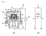
- Fig. 3 (a) is a sectional view of an igniter assembly for illustrating an assembly method and a distinguishing method of the present invention, and a schematic view of high-frequency resistance measurement circuits including the igniter assembly.
- Fig. 3(b) is an equivalent circuit diagram of high-frequency resistance measurement performed on the igniter assembly shown in Fig. 3(a) .
- a metallic cap 36 is fixed to the metallic collar 30 of the igniter assembly 10 shown in Fig. 1 , and a molded body of gas generating agent 35 is charged into an interior space of the metallic cap 36.
- a first measurement circuit having the center pin 21a as a terminal on one end side and the metallic cap 36 as a terminal on the other end side and a second measurement circuit having the eyelet pin 21b as a terminal on one end side and the metallic cap 36 as a terminal on the other end side are formed.
- the resin 31 and the glass member 22 serve as dielectrics.
- the glass member 22 becomes a capacitor C1
- the resin (the resin between the center pin 21a and the metallic collar 30) 31 becomes a capacitor C3
- the bridge wire 24 becomes a resistor R1 (2 ⁇ )
- the metallic cap 36, metallic collar 30 and center pin 21a become non-resistive conductors.
- the glass member 22 becomes a capacitor C1
- the resin (the resin between the eyelet pin 21b and the metallic collar 30) 31 becomes a capacitor C2
- the bridge wire 24 becomes a resistor R1 (2 ⁇ )
- the metallic cap 36, metallic collar 30 and eyelet pin 21b become non-resistive conductors.
- the first measurement circuit and second measurement circuit differ in the path along which the high frequency flows (in the first measurement circuit, the high frequency flows along the path of the capacitor C3, and in the second measurement circuit, the high frequency flows along the path of the capacitor C2), and therefore also differ in high-frequency resistance (pure resistance and/or impedance). Therefore, when an appropriate high frequency is selected and measurement is performed at this high frequency, a magnitude relationship occurs between the measured high-frequency resistance values. The reason for this is that in the gas generator shown in Fig.
- the center pin 21a and the eyelet pin 21b bend in the same direction in respective parts thereof that are covered by the resin 31, and in these resin 31 parts, the distance between the center pin 21a and metallic collar 30 differs from the distance between the eyelet pin 21b and metallic collar 30.
- the capacitance of the capacitor C3 differs from the capacitance of the capacitor C2.
- the gas generator is incorporated into a known automobile safety device (for example, a pretensioner of a seatbelt retractor, disclosed in JP-A No. 2003-267186 ), whereupon the gas generator is incorporated into an air bag device (for example, a seatbelt pretensioner) and then installed in a vehicle.
- a known automobile safety device for example, a pretensioner of a seatbelt retractor, disclosed in JP-A No. 2003-267186
- an air bag device for example, a seatbelt pretensioner
- Example 1 (igniter assembly of Fig. 2)
- the two measurement circuits (first measurement circuit and second measurement circuit) shown in Figs. 2(a) and 2(b) were prepared, whereupon the pure resistance value ( ⁇ ) and impedance ( ⁇ ) were measured while varying the frequency, as shown in Tables 1 and 2.
- the measurement values of the pure resistance and impedance of the igniter assembly vary according to the frequency of the high frequency, and therefore, by selecting a high frequency at which the magnitude relationship between the respective measurement values of the first measurement circuit and second measurement circuit is comparatively large, and performing the measurement at this frequency, it is possible to distinguish between the center pin and the eyelet pin without influence from measurement errors.
- Example 2 gas generator of Fig. 3
- the two measurement circuits (first measurement circuit and second measurement circuit) shown in Figs. 3(a) and 3(b) were prepared, whereupon the pure resistance value ( ⁇ ) and impedance ( ⁇ ) were measured while varying the frequency, as shown in Tables 3 and 4.
- the measurement values of the pure resistance and impedance of the igniter assembly vary according to the frequency of the high frequency, and therefore, by selecting a high frequency at which the magnitude relationship between the respective measurement values of the first measurement circuit and second measurement circuit is comparatively large and performing the measurement at this high frequency, it is possible to distinguish between the center pin and the eyelet pin without influence from measurement errors.
Landscapes
- Engineering & Computer Science (AREA)
- Manufacturing & Machinery (AREA)
- General Engineering & Computer Science (AREA)
- Air Bags (AREA)
Abstract
assembling an igniter assembly (10) in the device, the igniter assembly (10) having an electric igniter (20) provided with two pins (21a,21b) forming two measurement circuits by using the pins (21a,21b) and another member as terminals,
measuring pure resistances and/or impedances of the two measurement circuits,
distinguishing the first electroconductive pin (21a) from the second electroconductive pin (21b) from a magnitude relationship between the measured values, and
disposing the igniter assembly (10) into the device such that the electroconductive pins (21a,21b) correspond to predetermined power source electrodes.
Description
- The present invention relates to an assembly method for a device that employs electric ignition, such as an air bag device, and a method of distinguishing between two electroconductive pins provided in an electric igniter.
- In an electric igniter having two electroconductive pins (a center pin and an eyelet pin) for electrifying a heating wire (a body that generates heat through electric resistance) or an igniter assembly using the electric igniter, positive and negative electrodes are usually connected to predetermined electroconductive pins, and when a positive or negative electrode is connected to the wrong electroconductive pin, a defective product is obtained.
-
Fig. 1 illustrates the structure of aknown igniter assembly 10. Anelectric igniter 20 is coupled integrally to ametallic igniter collar 30 by aresin 31. - In the
electric igniter 20, acenter pin 21a is insulated from a metallic header (eyelet) 23 by aglass member 22 and connected to a heat-generating body (bridge wire) 24. Aneyelet pin 21b is connected to theeyelet 23 and connected to the heat-generating body (bridge wire) 24 via theeyelet 23. Anignition agent 26 is charged into atubular spacer 25 so as to press against the heat-generating body (bridge wire) 24. Theeyelet 23 and thetubular spacer 25 are covered from the outside by ametallic cover 27, together forming an ignition portion of theelectric igniter 20. Further, themetallic cover 27 of the ignition portion is covered by aresin cover 28 having an electric insulation property. Aspace 29 serves as a space for inserting a connector plug having a lead wire. - As shown in
Fig. 1 , theigniter assembly 10 has a structure in which aresin 31 is molded between theigniter 20 andigniter collar 30, and therefore it is impossible to distinguish between thecenter pin 21a and theeyelet pin 21b from the outer form thereof. - Conventionally, the
center pin 21a is distinguished from theeyelet pin 21b by means of X-ray projection, but X-ray projectors and X-ray lamps are both expensive, leading to an increase in maintenance costs that is reflected in the manufacturing costs of the igniter. -
JP-A No. 2001-165600 JP-A No. 2006-35970 - One of the inventions provides a method of assembling a device employing electric ignition by comprising assembling an igniter assembly in the device, the igniter assembly having an electric igniter provided with a first electroconductive pin and a second electroconductive pin, connected to a power source, the method comprising steps of:
- forming two measurement circuits by using the first electroconductive pin and the second electroconductive pin as a measurement terminal on one end side, respectively, and using another member provided in the igniter assembly as a terminal on the other end side with a pass through a dielectric provided in the igniter assembly,
- measuring pure resistances and/or impedances of the two measurement circuits, respectively, by applying a high frequency thereto separately,
- distinguishing the first electroconductive pin from the second electroconductive pin from a magnitude relationship (difference) between the measured pure resistance and/or impedance values, and
- then, disposing the igniter assembly to the device such that the first electroconductive pin and the second electroconductive pin correspond to predetermined power source electrodes, respectively.
- In other words, it is an assembly method for a device employing electric ignition, including a step of attaching an igniter assembly to the device,
wherein the igniter assembly has an electric igniter having a first electroconductive pin and a second electroconductive pin for connecting the electric igniter to a power source,
two measurement circuits passing through a dielectric provided in the igniter assembly are formed such that the first electroconductive pin or the second electroconductive pin serves as a measurement terminal on one end side and another member provided in the igniter assembly serves as a terminal on another end side, and
a high frequency is introduced separately into the two measurement circuits to measure pure resistances and/or impedances, and the first electroconductive pin is distinguished from the second electroconductive pin from a magnitude relationship (difference) between the measured pure resistance and/or impedance values, whereupon the igniter assembly is attached to the device such that the first electroconductive pin and the second electroconductive pin correspond to predetermined power source electrodes. - Another one of the inventions provides a method of distinguishing between a first electroconductive pin and a second electroconductive pin, provided in an electric igniter in an igniter assembly including the electric igniter, comprising steps of:
- forming two measurement circuits passing through a dielectric, provided in the igniter assembly, such that the first electroconductive pin and the second electroconductive pin serves as a measurement terminal on one end side and another member provided in the igniter assembly serves as a terminal on another end side; and
- measuring pure resistances and/or impedances of the two measurement circuits, respectively, by applying a high frequency thereto separately, and distinguishing between the first electroconductive pin and the second electroconductive pin from a magnitude relationship (difference) between the measured pure resistance and/or impedance values.
- The present invention will become more fully understood from the detailed description given hereinbelow and the accompanying drawings which are given by way of illustration only, and thus are not limitative of the present invention and wherein:
-
Fig. 1 shows a vertical cross-sectional view of a known igniter assembly to which the present invention is applied; - In
Fig. 2, (a) shows a sectional view of an igniter assembly for illustrating an assembly method and a distinguishing method of the present invention, and a schematic view of high-frequency resistance measurement circuits including the igniter assembly, and (b) shows an equivalent circuit diagram of the igniter assembly shown in (a) in high-frequency resistance measurement; and - In
Fig. 3, (a) shows a sectional view of a gas generator having an igniter assembly for illustrating an assembly method and a distinguishing method of the present invention, and a schematic view of high-frequency resistance measurement circuits including the igniter assembly, and (b) shows an equivalent circuit diagram of the gas generator shown in (a) in high-frequency resistance measurement. - The present invention provides an assembly method for a device that employs electric ignition, such as an air bag device, with which it is possible to distinguish between two electroconductive pins provided in an igniter assembly and an electric igniter, thereby improving the reliability of the device.
- The present invention also provides a method of distinguishing between two electroconductive pins provided in an igniter assembly and an electric igniter.
- By employing a commercially available high-frequency resistance measuring device, the sign, positive or negative, of the two electroconductive pins can be confirmed easily. Hence, in comparison with a conventional method employing an X-ray projector, manufacturing costs can be reduced.
- Various devices, such as an occupant-protecting air bag device (a gas generator for an air bag) or a seatbelt pretensioner installed in a vehicle such as an automobile, may be cited as examples of a device employing electric ignition.
- An igniter assembly in which a collar member is incorporated into a lower portion (including a part of the electroconductive pins) of an electric igniter via a resin, and a gas generator in which a cap member is fixed to the collar member of the igniter assembly and a gas generating agent is charged between the electric igniter and the cap, or in other words a gas generator having an igniter assembly, may be cited as examples of an igniter assembly.
- The present invention preferably provides the assembly method, wherein the dielectric is an electric insulation cover covering an ignition portion of the electric igniter.
- The present invention preferably provides the assembly method, wherein the dielectric is a resin which integrally couples a metallic igniter collar to the electric igniter.
- By employing a commercially available high-frequency resistance measuring device, the sign, positive or negative, of the two electroconductive pins can be confirmed easily. Hence, in comparison with a conventional method employing an X-ray projector, manufacturing costs can be reduced.
- The present invention preferably provides the method of distinguishing between a first electroconductive pin and a second electroconductive pin, wherein the dielectric is an electric insulation cover covering an ignition portion of the electric igniter.
- The present invention preferably provides the method of distinguishing between a first electroconductive pin and a second electroconductive pin, wherein the dielectric is a resin which integrally couples a metallic igniter collar to the electric igniter.
- By applying the distinguishing method of the present invention, it is possible to distinguish between two electroconductive pins provided in an igniter assembly easily and at a lower cost than a conventional method. Therefore, when assembling an automobile safety device such as an air bag device (a gas generator for an air bag) or a seatbelt pretensioner, the respective electroconductive pins can be attached appropriately to the corresponding ignition power source electrodes, without confusing the two electroconductive pins, as a result of which the reliability of the device is improved. Embodiment of Invention
- (1) Assembly method or distinguishing method in
Fig. 2
Fig. 2 (a) is a sectional view of an igniter assembly for illustrating an assembly method and a distinguishing method of the present invention, and a schematic view of high-frequency resistance measurement circuits including the igniter assembly.Fig. 2(b) is an equivalent circuit diagram of high-frequency resistance measurement performed on the igniter assembly shown inFig. 2(a) .
Theigniter assembly 10 is identical to the igniter assembly shown inFig. 1 , in which an ignition portion (themetallic cover 27 and the interior thereof) of theelectric igniter 20 is covered by the resin cover 28 (electric insulation cover), which has an electric insulation property.
In high-frequency resistance measurement of theigniter assembly 10, a first measurement circuit having the center pin (first electroconductive pin) 21a as a terminal on one end side and theresin cover 28 as a terminal on the other end side and a second measurement circuit having the eyelet pin (second electroconductive pin) 21b as a terminal on one end side and theresin cover 28 as a terminal on the other end side are formed. In these circuits, theresin cover 28 and theglass member 22 serve as dielectrics.
A high-frequencyresistance measuring device 40 is disposed on the first measurement circuit and second measurement circuit. A device described in Examples may be used as the high-frequency resistance measuring device.
When a high frequency is introduced into the first measurement circuit (between theresin cover 28 and thecenter pin 21a) by the high-frequencyresistance measuring device 40, the resin cover (dielectric) 28 becomes a capacitor C0, theglass member 22 becomes a capacitor C1, thebridge wire 24 becomes a resistor R1 (2Ω), and themetallic cover 27,eyelet 23 andcenter pin 21a become non-resistive conductors.
Meanwhile, when a high frequency is introduced into the second measurement circuit (between theresin cover 28 and theeyelet pin 21b) by the high-frequencyresistance measuring device 40, the resin cover (dielectric) 28 becomes a capacitor C0, and themetallic cover 27,eyelet 23 andeyelet pin 21b become non-resistive conductors.
Hence, the first measurement circuit and second measurement circuit differ in circuit configuration and the path along which the high frequency flows, and therefore also differ in high-frequency resistance (pure resistance and/or impedance). Therefore, when an appropriate high frequency is selected and measurement is performed at this high frequency, a magnitude relationship occurs between the measured high-frequency resistance values. Accordingly, by measuring the high-frequency resistance (pure resistance and/or impedance) at different high frequencies in advance with respect to an igniter assembly (measurement reference product) having a specific structure and serving as a measurement subject, confirming the frequency of a high frequency at which a magnitude relationship occurs between the high-frequency resistance values measured in relation to the first measurement circuit and second measurement circuit, and using this high frequency to measure the high-frequency resistances (pure resistances and/or impedances) of the first measurement circuit and second measurement circuit, it is possible to distinguish between the center pin (first electroconductive pin) and eyelet pin (second electroconductive pin) easily from the magnitude relationship between the high-frequency resistance values of the first measurement circuit and second measurement circuit.
After distinguishing between the two electroconductive pins (the center pin and eyelet pin) of the igniter assembly in this manner, the igniter assembly is incorporated into a known gas generator (for example, a gas generator used in a seatbelt pretensioner, disclosed inJP-A No. 2005-225274 Figs. 1 , 6 and 8 ofJP-A No. 2001-16500 - (2) Assembly method and distinguishing method in
Fig. 3 -
Fig. 3 (a) is a sectional view of an igniter assembly for illustrating an assembly method and a distinguishing method of the present invention, and a schematic view of high-frequency resistance measurement circuits including the igniter assembly.Fig. 3(b) is an equivalent circuit diagram of high-frequency resistance measurement performed on the igniter assembly shown inFig. 3(a) . - In
Fig. 3(a) , an openingportion 37 of ametallic cap 36 is fixed to themetallic collar 30 of theigniter assembly 10 shown inFig. 1 , and a molded body ofgas generating agent 35 is charged into an interior space of themetallic cap 36. - In high-frequency resistance measurement of a
gas generator 50, a first measurement circuit having thecenter pin 21a as a terminal on one end side and themetallic cap 36 as a terminal on the other end side and a second measurement circuit having theeyelet pin 21b as a terminal on one end side and themetallic cap 36 as a terminal on the other end side are formed. In these circuits, theresin 31 and theglass member 22 serve as dielectrics. - When a high frequency is introduced into the first measurement circuit (between the
metallic cap 36 and thecenter pin 21a) by the high-frequencyresistance measuring device 40, theglass member 22 becomes a capacitor C1, the resin (the resin between thecenter pin 21a and the metallic collar 30) 31 becomes a capacitor C3, thebridge wire 24 becomes a resistor R1 (2Ω), and themetallic cap 36,metallic collar 30 andcenter pin 21a become non-resistive conductors. - Meanwhile, when a high frequency is introduced into the second measurement circuit (between the
metallic cap 36 and theeyelet pin 21b) by the high-frequencyresistance measuring device 40, theglass member 22 becomes a capacitor C1, the resin (the resin between theeyelet pin 21b and the metallic collar 30) 31 becomes a capacitor C2, thebridge wire 24 becomes a resistor R1 (2Ω), and themetallic cap 36,metallic collar 30 andeyelet pin 21b become non-resistive conductors. - Hence, the first measurement circuit and second measurement circuit differ in the path along which the high frequency flows (in the first measurement circuit, the high frequency flows along the path of the capacitor C3, and in the second measurement circuit, the high frequency flows along the path of the capacitor C2), and therefore also differ in high-frequency resistance (pure resistance and/or impedance). Therefore, when an appropriate high frequency is selected and measurement is performed at this high frequency, a magnitude relationship occurs between the measured high-frequency resistance values. The reason for this is that in the gas generator shown in
Fig. 3 (a) , thecenter pin 21a and theeyelet pin 21b bend in the same direction in respective parts thereof that are covered by theresin 31, and in theseresin 31 parts, the distance between thecenter pin 21a andmetallic collar 30 differs from the distance between theeyelet pin 21b andmetallic collar 30. Hence, the capacitance of the capacitor C3 differs from the capacitance of the capacitor C2. - Accordingly, by measuring the high-frequency resistance (pure resistance and/or impedance) at different high frequencies in advance with respect to an igniter assembly (measurement reference product) having a specific structure and serving as a measurement subject, confirming the frequency of a high frequency at which a magnitude relationship occurs between the high-frequency resistance values measured in relation to the first measurement circuit and second measurement circuit, and using this high frequency to measure the high-frequency resistances (pure resistances and/or impedances) of the first measurement circuit and second measurement circuit, it is possible to distinguish between the center pin (first electroconductive pin) and eyelet pin (second electroconductive pin) easily from the magnitude relationship between the high-frequency resistance values of the first measurement circuit and second measurement circuit.
- After distinguishing between the two electroconductive pins (the center pin and eyelet pin) of the gas generator in this manner, the gas generator is incorporated into a known automobile safety device (for example, a pretensioner of a seatbelt retractor, disclosed in
JP-A No. 2003-267186 - The two measurement circuits (first measurement circuit and second measurement circuit) shown in
Figs. 2(a) and 2(b) were prepared, whereupon the pure resistance value (Ω) and impedance (Ω) were measured while varying the frequency, as shown in Tables 1 and 2. A "Network Analyzer, Model: 8753ES, Frequency Range: 30kHz to 3GHz", manufactured by Agilent Technologies Inc., was used as the high-frequency resistance measuring device.Table 1 Frequency (MHz) Pure Resistance (Ω) First measurement circuit Second measurement circuit Difference 3 202.500 233.500 -31.000 4 156.000 173.500 -17.500 5 116.000 134.130 -18.130 6 89.250 106.630 -17.380 7 73.130 86.500 -13.370 8 57.880 70.750 -12.870 9 45.690 58.190 -12.500 10 37.810 47.940 -10.130 15 8.880 16.690 -7.810 20 13.219 16.906 -3.687 30 8.188 9.313 -1.125 40 12.000 11.859 0.141 50 9.578 8.797 0.781 60 5.570 4.297 1.273 70 5.336 4.313 1.023 80 6.875 6.953 -0.078 90 7.938 8.914 -0.976 100 7.031 6.340 0.691 150 4.141 2.277 1.864 200 5.466 3.151 2.315 300 77.711 75.297 2.414 Table 2 Frequency (MHz) Impedance (Ω) First measurement circuit Second measurement circuit Difference 3 5435.074 5224.221 210.853 4 4108.962 3987.177 121.785 5 3296.841 3223.692 73.149 6 2757.245 2705.502 51.743 7 2365.631 2334.103 31.528 8 2074.208 2049.721 24.487 9 1844.666 1827.127 17.539 10 1662.430 1648.097 14.333 15 1110.636 1106.926 3.710 20 826.046 825.113 0.933 30 543.622 544.490 -0.868 40 399.520 400.176 -0.656 50 312.777 312.924 -0.147 60 254.551 254.406 0.145 70 209.048 208.295 0.753 80 170.549 168.573 1.976 90 136.701 133.059 3.642 100 127.624 126.030 1.594 150 48.491 47.547 0.944 200 14.943 15.883 -0.940 300 193.913 198.959 -5.046 - As is evident from Tables 1 and 2, a magnitude relationship occurred clearly in both the pure resistance and the impedance between the first measurement circuit (between the
resin cover 28 and thecenter pin 21a) and the second measurement circuit (between theresin cover 28 and theeyelet pin 21b) at each frequency. It is therefore possible to distinguish between the two electroconductive pins of the igniter assembly easily. Hence, confusion does not occur between the positive and negative electrodes of the ignition power source that is connected to the two electroconductive pins when incorporating the igniter assembly in a device, and the device can be assembled reliably and easily. - As shown in Tables 1 and 2, the measurement values of the pure resistance and impedance of the igniter assembly vary according to the frequency of the high frequency, and therefore, by selecting a high frequency at which the magnitude relationship between the respective measurement values of the first measurement circuit and second measurement circuit is comparatively large, and performing the measurement at this frequency, it is possible to distinguish between the center pin and the eyelet pin without influence from measurement errors.
- The two measurement circuits (first measurement circuit and second measurement circuit) shown in
Figs. 3(a) and 3(b) were prepared, whereupon the pure resistance value (Ω) and impedance (Ω) were measured while varying the frequency, as shown in Tables 3 and 4. A "Vector Network Analyzer, Model: ZVRE, Frequency Range: 10kHz to 4GHz", manufactured by ROHDE & SCHWARZ, Inc. was used as the high-frequency resistance measuring device.Table 3 Frequency (MHz) Pure Resistance (Ω) First measurement circuit Second measurement circuit Difference 10 188.560 185.810 2.750 15 111.750 106.750 5.000 20 81.969 79.437 2.532 30 48.156 47.031 1.125 40 36.625 35.516 1.109 50 28.578 27.156 1.422 60 22.906 21.109 1.797 70 19.703 18.383 1.320 80 17.102 16.086 1.016 90 15.148 14.273 0.875 100 14.000 13.109 0.891 Table 4 Frequency (MHz) Impedance (Ω) First measurement circuit Second measurement circuit Difference 10 1633.295 1601.979 31.316 15 1091.104 1063.054 28.050 20 828.691 809.123 19.568 30 560.857 549.356 11.501 40 421.799 411.310 10.489 50 335.653 327.107 8.546 60 276.437 270.199 6.238 70 232.448 227.033 5.445 80 198.717 193.886 4.831 90 171.725 167.378 4.347 100 149.488 145.612 3.876 - As is evident from Tables 3 and 4, a magnitude relationship occurred clearly in both the pure resistance and the impedance between the first measurement circuit (between the
metallic cap 36 and thecenter pin 21a) and the second measurement circuit (between themetallic cap 36 and theeyelet pin 21b) at each frequency. It is therefore possible to distinguish between the two electroconductive pins of the igniter assembly provided in the gas generator easily. Hence, confusion does not occur between the positive and negative electrodes of the ignition power source that is connected to the two electroconductive pins when incorporating the igniter assembly in a device, and the device can be assembled reliably and easily. - As shown in Tables 3 and 4, the measurement values of the pure resistance and impedance of the igniter assembly vary according to the frequency of the high frequency, and therefore, by selecting a high frequency at which the magnitude relationship between the respective measurement values of the first measurement circuit and second measurement circuit is comparatively large and performing the measurement at this high frequency, it is possible to distinguish between the center pin and the eyelet pin without influence from measurement errors.
- As is evident from the high-frequency resistance measurement results shown in Tables 1 to 4, it is possible to distinguish between the two electroconductive pins of an igniter assembly (including a gas generator having an igniter assembly) by measuring either one of the pure resistance and the impedance. It is also possible to distinguish between the two electroconductive pins by measuring both the pure resistance and the impedance.
- The invention thus described, it will be obvious that the same may be varied in many ways. Such variations are not to be regarded as a departure from the spirit and scoped of the invention, and all such modifications as would be obvious to one skilled in the art are intended to be included within the scope of the following claims.
Claims (6)
- A method of assembling a device employing electric ignition by comprising assembling an igniter assembly in the device, the igniter assembly having an electric igniter provided with a first electroconductive pin and a second electroconductive pin, connected to a power source, the method comprising steps of:forming two measurement circuits by using the first electroconductive pin and the second electroconductive pin as a measurement terminal on one end side, respectively, and using another member provided in the igniter assembly as a terminal on the other end side with a pass through a dielectric provided in the igniter assembly,measuring pure resistances and/or impedances of the two measurement circuits, respectively, by applying a high frequency thereto separately,distinguishing the first electroconductive pin from the second electroconductive pin from a magnitude relationship (difference) between the measured pure resistance and/or impedance values, andthen, disposing the igniter assembly to the device such that the first electroconductive pin and the second electroconductive pin correspond to predetermined power source electrodes, respectively.
- The assembly method according to claim 1,
wherein the dielectric is an electric insulation cover covering an ignition portion of the electric igniter. - The assembly method according to claim 1, wherein the dielectric is a resin which integrally couples a metallic igniter collar to the electric igniter.
- A method of distinguishing between a first electroconductive pin and a second electroconductive pin, provided in an electric igniter in an igniter assembly including the electric igniter, comprising steps of:forming two measurement circuits passing through a dielectric, provided in the igniter assembly, such that the first electroconductive pin and the second electroconductive pin serves as a measurement terminal on one end side and another member provided in the igniter assembly serves as a terminal on another end side; andmeasuring pure resistances and/or impedances of the two measurement circuits, respectively, by applying a high frequency thereto separately, anddistinguishing between the first electroconductive pin and the second electroconductive pin from a magnitude relationship (difference) between the measured pure resistance and/or impedance values.
- The method of distinguishing between a first electroconductive pin and a second electroconductive pin according to claim 4, wherein the dielectric is an electric insulation cover covering an ignition portion of the electric igniter.
- The method of distinguishing between a first electroconductive pin and a second electroconductive pin according to claim 4, wherein the dielectric is a resin which integrally couples a metallic igniter collar to the electric igniter.
Applications Claiming Priority (1)
| Application Number | Priority Date | Filing Date | Title |
|---|---|---|---|
| JP2006342118A JP4916868B2 (en) | 2006-12-20 | 2006-12-20 | Device assembly method using electrical ignition |
Publications (2)
| Publication Number | Publication Date |
|---|---|
| EP1936320A1 true EP1936320A1 (en) | 2008-06-25 |
| EP1936320B1 EP1936320B1 (en) | 2009-12-02 |
Family
ID=39170934
Family Applications (1)
| Application Number | Title | Priority Date | Filing Date |
|---|---|---|---|
| EP07024541A Active EP1936320B1 (en) | 2006-12-20 | 2007-12-18 | Assembly method for device employing electric ignition |
Country Status (4)
| Country | Link |
|---|---|
| US (1) | US7614344B2 (en) |
| EP (1) | EP1936320B1 (en) |
| JP (1) | JP4916868B2 (en) |
| DE (1) | DE602007003548D1 (en) |
Cited By (1)
| Publication number | Priority date | Publication date | Assignee | Title |
|---|---|---|---|---|
| US20230271586A1 (en) * | 2020-05-14 | 2023-08-31 | Daicel Corporation | Igniter assembly and gas generator provided with same |
Families Citing this family (9)
| Publication number | Priority date | Publication date | Assignee | Title |
|---|---|---|---|---|
| JP4813904B2 (en) * | 2006-01-06 | 2011-11-09 | 日本化薬株式会社 | Ignition device, manufacturing method thereof, gas generator for airbag, and gas generator for seat belt pretensioner |
| JP4996481B2 (en) * | 2006-01-06 | 2012-08-08 | 日本化薬株式会社 | Ignition device, gas generator for airbag, and gas generator for seat belt pretensioner |
| JP4916868B2 (en) * | 2006-12-20 | 2012-04-18 | 株式会社ダイセル | Device assembly method using electrical ignition |
| CN101772689A (en) * | 2007-06-13 | 2010-07-07 | 日本化药株式会社 | Ignition device, gas generator for air bag, and gas generator for seatbelt pretensioner |
| US8276516B1 (en) | 2008-10-30 | 2012-10-02 | Reynolds Systems, Inc. | Apparatus for detonating a triaminotrinitrobenzene charge |
| JP5897417B2 (en) | 2012-07-13 | 2016-03-30 | 株式会社ダイセル | Cover member for igniter |
| JP6954520B2 (en) * | 2017-12-05 | 2021-10-27 | 株式会社ダイセル | Ignizer assembly and gas generator |
| JP7219687B2 (en) * | 2019-09-20 | 2023-02-08 | 株式会社ダイセル | Ignitor assembly, gas generator, and method for assembling igniter assembly |
| EP3839413B1 (en) * | 2019-12-19 | 2022-03-16 | Schott Ag | Metal fixing material feedthrough, method for the production and uses thereof |
Citations (5)
| Publication number | Priority date | Publication date | Assignee | Title |
|---|---|---|---|---|
| JP2001016500A (en) | 1999-07-01 | 2001-01-19 | Asahi Optical Co Ltd | Electronic endoscope |
| JP2001165600A (en) | 1999-09-27 | 2001-06-22 | Daicel Chem Ind Ltd | Initiator assembly |
| JP2003267186A (en) | 2002-03-12 | 2003-09-25 | Ashimori Ind Co Ltd | Pretensioner for seat belt retractor |
| JP2005225274A (en) | 2004-02-10 | 2005-08-25 | Daicel Chem Ind Ltd | Gas generator |
| EP1621413A1 (en) * | 2004-07-26 | 2006-02-01 | Daicel Chemical Industries, Ltd. | Igniter assembly |
Family Cites Families (12)
| Publication number | Priority date | Publication date | Assignee | Title |
|---|---|---|---|---|
| US3496496A (en) * | 1966-03-21 | 1970-02-17 | Gen Rf Fittings Inc | Precision coaxial connector |
| JPS5317375A (en) * | 1976-07-31 | 1978-02-17 | Nippon Oils & Fats Co Ltd | Resistance meter for electric blasting |
| JPH0227600B2 (en) * | 1985-09-19 | 1990-06-18 | Nippon Oils & Fats Co Ltd | DOTSUSHIKENKI |
| JPS63161399A (en) * | 1986-12-24 | 1988-07-05 | 日本化薬株式会社 | Firework igniter |
| US5099762A (en) * | 1990-12-05 | 1992-03-31 | Special Devices, Incorporated | Electrostatic discharge immune electric initiator |
| US5602359A (en) * | 1995-08-14 | 1997-02-11 | Ici Americas, Inc. | Airbag ingniter with integral sensitivity identification |
| US5732634A (en) * | 1996-09-03 | 1998-03-31 | Teledyne Industries, Inc. | Thin film bridge initiators and method of manufacture |
| FR2800865B1 (en) * | 1999-11-05 | 2001-12-07 | Livbag Snc | PYROTECHNIC INITIATOR WITH PHOTOGRAVE FILAMENT PROTECTED AGAINST ELECTROSTATIC DISCHARGES |
| US20050189753A1 (en) | 2004-02-10 | 2005-09-01 | Kazuhiro Kato | Gas generator |
| US20060017269A1 (en) | 2004-07-26 | 2006-01-26 | Daicel Chemical Industries, Ltd. | Igniter assembly |
| US7210703B2 (en) * | 2004-10-26 | 2007-05-01 | Autoliv Asp, Inc. | One-piece initiator device for inflators |
| JP4916868B2 (en) * | 2006-12-20 | 2012-04-18 | 株式会社ダイセル | Device assembly method using electrical ignition |
-
2006
- 2006-12-20 JP JP2006342118A patent/JP4916868B2/en active Active
-
2007
- 2007-12-18 EP EP07024541A patent/EP1936320B1/en active Active
- 2007-12-18 DE DE602007003548T patent/DE602007003548D1/en active Active
- 2007-12-19 US US11/960,570 patent/US7614344B2/en active Active
Patent Citations (7)
| Publication number | Priority date | Publication date | Assignee | Title |
|---|---|---|---|---|
| JP2001016500A (en) | 1999-07-01 | 2001-01-19 | Asahi Optical Co Ltd | Electronic endoscope |
| JP2001165600A (en) | 1999-09-27 | 2001-06-22 | Daicel Chem Ind Ltd | Initiator assembly |
| EP1217325A1 (en) * | 1999-09-27 | 2002-06-26 | Daicel Chemical Industries, Ltd. | Initiator assembly |
| JP2003267186A (en) | 2002-03-12 | 2003-09-25 | Ashimori Ind Co Ltd | Pretensioner for seat belt retractor |
| JP2005225274A (en) | 2004-02-10 | 2005-08-25 | Daicel Chem Ind Ltd | Gas generator |
| EP1621413A1 (en) * | 2004-07-26 | 2006-02-01 | Daicel Chemical Industries, Ltd. | Igniter assembly |
| JP2006035970A (en) | 2004-07-26 | 2006-02-09 | Daicel Chem Ind Ltd | Igniter assembly |
Cited By (2)
| Publication number | Priority date | Publication date | Assignee | Title |
|---|---|---|---|---|
| US20230271586A1 (en) * | 2020-05-14 | 2023-08-31 | Daicel Corporation | Igniter assembly and gas generator provided with same |
| US11993222B2 (en) * | 2020-05-14 | 2024-05-28 | Daicel Corporation | Igniter assembly and gas generator provided with same |
Also Published As
| Publication number | Publication date |
|---|---|
| US7614344B2 (en) | 2009-11-10 |
| JP4916868B2 (en) | 2012-04-18 |
| US20080148983A1 (en) | 2008-06-26 |
| DE602007003548D1 (en) | 2010-01-14 |
| JP2008151464A (en) | 2008-07-03 |
| EP1936320B1 (en) | 2009-12-02 |
Similar Documents
| Publication | Publication Date | Title |
|---|---|---|
| EP1936320B1 (en) | Assembly method for device employing electric ignition | |
| CN101750529B (en) | Capacitive divider device, voltage sensor, trip device module and electrical protection apparatus provided with such a device | |
| JP5795470B2 (en) | High voltage test equipment | |
| CA2761331A1 (en) | System and method for sensing voltage in medium-to-high voltage applications | |
| JP5845057B2 (en) | Current detector | |
| US20180131123A1 (en) | Connector | |
| CN113140380A (en) | Resistor array, measuring circuit with a resistor array and method for producing a composite of a strip-shaped material for a resistor array | |
| EP1308691B1 (en) | Electric initiator and initiator assembly using it | |
| CN105842515A (en) | Device comprising elements for measuring current and process for manufacturing such a device | |
| US20090158953A1 (en) | Glass-Metal Feedthrough, a Method of Fabricating It, and an Electro-Pyrotechnic Initiator Including It | |
| CN116525303B (en) | An aluminum electrolytic capacitor terminal assembly and its manufacturing method | |
| US4721474A (en) | High tension feeding cable and a method of manufacturing the same | |
| CA2569979A1 (en) | Vehicle air bag electrical system | |
| CN206832921U (en) | Module samples wire harness on off test frock | |
| CN110301073B (en) | Connector structure | |
| CN111649850B (en) | Leadless packaging pressure sensor and packaging method thereof | |
| JP6054243B2 (en) | Gas sensor | |
| JP7801462B2 (en) | BATTERY MANAGEMENT SYSTEM, BATTERY PACK, AND METHOD FOR CONTROLLING THE DISCHARGE OF AT LEAST ONE BATTERY CELL - Patent application | |
| KR102554402B1 (en) | Calibration appratus and method thereof | |
| JP2009133514A (en) | Device assembly method using electrical ignition | |
| US20220089044A1 (en) | Device for electrical charging of a vehicle battery of an electrically operated vehicle, and method for manufacturing a device for electrical charging of a vehicle battery of an electrically operated vehicle | |
| KR20120047581A (en) | Junction box for vehicle having test pin of tap terminal type | |
| US20250216243A1 (en) | Fill level gauge | |
| CN106707112B (en) | Capacitor testing device | |
| JP5658734B2 (en) | Valve unit |
Legal Events
| Date | Code | Title | Description |
|---|---|---|---|
| PUAI | Public reference made under article 153(3) epc to a published international application that has entered the european phase |
Free format text: ORIGINAL CODE: 0009012 |
|
| AK | Designated contracting states |
Kind code of ref document: A1 Designated state(s): AT BE BG CH CY CZ DE DK EE ES FI FR GB GR HU IE IS IT LI LT LU LV MC MT NL PL PT RO SE SI SK TR |
|
| AX | Request for extension of the european patent |
Extension state: AL BA HR MK RS |
|
| 17P | Request for examination filed |
Effective date: 20081027 |
|
| 17Q | First examination report despatched |
Effective date: 20081218 |
|
| AKX | Designation fees paid |
Designated state(s): DE |
|
| GRAP | Despatch of communication of intention to grant a patent |
Free format text: ORIGINAL CODE: EPIDOSNIGR1 |
|
| GRAS | Grant fee paid |
Free format text: ORIGINAL CODE: EPIDOSNIGR3 |
|
| GRAA | (expected) grant |
Free format text: ORIGINAL CODE: 0009210 |
|
| AK | Designated contracting states |
Kind code of ref document: B1 Designated state(s): DE |
|
| REF | Corresponds to: |
Ref document number: 602007003548 Country of ref document: DE Date of ref document: 20100114 Kind code of ref document: P |
|
| PLBE | No opposition filed within time limit |
Free format text: ORIGINAL CODE: 0009261 |
|
| STAA | Information on the status of an ep patent application or granted ep patent |
Free format text: STATUS: NO OPPOSITION FILED WITHIN TIME LIMIT |
|
| 26N | No opposition filed |
Effective date: 20100903 |
|
| PGFP | Annual fee paid to national office [announced via postgrant information from national office to epo] |
Ref country code: DE Payment date: 20251211 Year of fee payment: 19 |