EP1936182A1 - Method for manufacturing a fluid injector - Google Patents
Method for manufacturing a fluid injector Download PDFInfo
- Publication number
- EP1936182A1 EP1936182A1 EP06025879A EP06025879A EP1936182A1 EP 1936182 A1 EP1936182 A1 EP 1936182A1 EP 06025879 A EP06025879 A EP 06025879A EP 06025879 A EP06025879 A EP 06025879A EP 1936182 A1 EP1936182 A1 EP 1936182A1
- Authority
- EP
- European Patent Office
- Prior art keywords
- needle
- solid state
- actuator unit
- state actuator
- force
- Prior art date
- Legal status (The legal status is an assumption and is not a legal conclusion. Google has not performed a legal analysis and makes no representation as to the accuracy of the status listed.)
- Granted
Links
Images


Classifications
-
- F—MECHANICAL ENGINEERING; LIGHTING; HEATING; WEAPONS; BLASTING
- F02—COMBUSTION ENGINES; HOT-GAS OR COMBUSTION-PRODUCT ENGINE PLANTS
- F02M—SUPPLYING COMBUSTION ENGINES IN GENERAL WITH COMBUSTIBLE MIXTURES OR CONSTITUENTS THEREOF
- F02M61/00—Fuel-injectors not provided for in groups F02M39/00 - F02M57/00 or F02M67/00
- F02M61/16—Details not provided for in, or of interest apart from, the apparatus of groups F02M61/02 - F02M61/14
- F02M61/168—Assembling; Disassembling; Manufacturing; Adjusting
-
- F—MECHANICAL ENGINEERING; LIGHTING; HEATING; WEAPONS; BLASTING
- F02—COMBUSTION ENGINES; HOT-GAS OR COMBUSTION-PRODUCT ENGINE PLANTS
- F02M—SUPPLYING COMBUSTION ENGINES IN GENERAL WITH COMBUSTIBLE MIXTURES OR CONSTITUENTS THEREOF
- F02M51/00—Fuel-injection apparatus characterised by being operated electrically
- F02M51/06—Injectors peculiar thereto with means directly operating the valve needle
- F02M51/0603—Injectors peculiar thereto with means directly operating the valve needle using piezoelectric or magnetostrictive operating means
-
- F—MECHANICAL ENGINEERING; LIGHTING; HEATING; WEAPONS; BLASTING
- F02—COMBUSTION ENGINES; HOT-GAS OR COMBUSTION-PRODUCT ENGINE PLANTS
- F02M—SUPPLYING COMBUSTION ENGINES IN GENERAL WITH COMBUSTIBLE MIXTURES OR CONSTITUENTS THEREOF
- F02M2200/00—Details of fuel-injection apparatus, not otherwise provided for
- F02M2200/80—Fuel injection apparatus manufacture, repair or assembly
- F02M2200/8092—Fuel injection apparatus manufacture, repair or assembly adjusting or calibration
Definitions
- the invention relates to a method for manufacturing a fluid injector, in particular a fluid injector for metering fuel to a combustion chamber of an internal combustion engine.
- Fluid injectors are in widespread use, in particular for internal combustion engines where they may be arranged in order to dose the fluid into the intake manifold of the internal combustion engine or directly into the combustion chamber of a cylinder of the internal combustion engine.
- fluid injectors need to be designed such that they are adapted to dose fluid very precisely.
- more and more fluid injectors are equipped with solid state actuators, in particular piezoelectric actuators.
- the respective fluid injector may be suited to dose fluid under very high pressure.
- the pressure may be, in the case of a gasoline engine, for example in the range of up to 200 Bar and in the case of a diesel engine, in the range of up to 2,000 Bar.
- the invention is distinguished by a method for manufacturing a fluid injector, comprising a housing with a needle, preventing fluid dosing in a closing position, in which the needle is sealingly in contact with a seat, and enabling fluid dosing apart from the closing position.
- the fluid injector further comprises a solid state actuator unit being operably connected to the needle and acting on the needle. It further comprises a return spring being preloaded to exert a force acting to bring the needle in the closing position.
- the method for manufacturing comprises the steps of exerting a given test force on the solid state actuator, being given in a way to ensure that the needle receives a given seat reaction force from the seat with the fluid injector being preassembled with the housing, the needle, the return spring and the solid state actuator unit. While exerting the given test force a characteristic quantity of the solid state actuator unit is measured as a first quantity value.
- the characteristic quantity of the solid state actuator unit is measured as a second quantity value, in particular under a given condition of the solid state actuator unit, in particular a condition being characteristic for an intended closing position of the needle as the second quantity value.
- the solid state actuator unit is also in the given condition when the first quantity value is measured.
- the seat reaction force is within an acceptable range after the assembly of the at least one element exerting a force on the solid state actuator unit is determined depending on the first and second quantity value.
- the insight is used that the first and second quantity values have a given relation to the seat reaction force acting on the needle in its presumed closing position. This therefore enables in a simple way to determine whether the thus manufactured fluid injector has a leak rate in its presumed closing position of the needle below a specified limit.
- the characteristic quantity of the solid state actuator is its capacitance. This has the advantage that the capacitance may be determined in a simple way, in particular if the solid state actuator unit comprises a piezoelectric component.
- the at least one element comprises a thermal compensator or a calibration spring.
- a fluid injector may be embodied as a fuel injector, that is suitable for injecting fuel into a gasoline engine or that may be suitable for injecting fuel into a diesel engine.
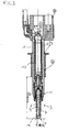
- the fluid injector comprises a housing 1 and a valve body 3.
- the housing 1 takes in a fluid duct 2.
- the valve body 3 comprises a cartridge 5, a valve body recess 7 and a needle 9, that is inserted into the valve body recess 7 and is guided in the area of the valve body recess 7.
- the needle 9 is of an outward opening type but it may also be of an inward opening type.
- a return spring 11 is provided, that is preloaded to exert a force acting to bring the needle 9 in the closing position.
- the return spring 11 rests with one of its free ends on the cartridge 5 and is coupled with its other free end with the needle 9.
- a solid state actuator unit 13 is taken in the housing 1 and is operatively connected to the needle 9. Depending on control signals applied to the solid state actuator unit 13 in the fully assembled state of the fluid injector a force from the solid state actuator unit 13 is exerted on the needle 9.
- the solid state actuator unit 13 preferably comprises a tube spring being fixed on its free ends to a bottom and respectively a top cap and taking in a solid state actuator.
- the solid state actuator may be preferably a piezoelectric actuator, but it may also be a different kind of solid state actuator being known to the person skilled in the art for such a purpose.
- a nozzle 15 is formed in the area of one of the axial ends of cartridge 5, through which the fluid is dosed outside of a closing position of the needle 9, in which the needle prevents a fluid dosing and is therefore sealingly in contact with a seat 16 being formed in the valve body 3 and in particular in the cartridge 5.
- the needle may be in its closing position or in an intermediate position and in particular in an opening position.
- the fluid injector further comprises a thermal compensator unit 17, which comprises a piston 19 with a rod 21.
- the thermal compensator unit 17 is designed to compensate for different thermal expansion coefficients of the solid state actuator unit 13 and the housing 1 and valve body 3.
- the thermal compensator unit 17 operates on a hydraulic basis.
- a force exerted on the solid state actuator unit 13 by the thermal compensator unit 17 is referred to as thermal compensator force F_TC.
- the fluid injector further comprises a calibration spring 25 which is preloaded by respectively positioning a calibration element.
- the calibration element preferably comprises a calibration shaft 27 which is connected to at least one calibration leg 29 acting on the calibration spring 25.
- the calibration shaft 27 is in the fully assembled and tested and calibrated state of the fluid injector in a fixed position relative to the housing 1 and may be, for example, fixed by a crimping connection.
- the calibration spring 25 exerts a calibration spring force F_CAL on the solid state actuator unit 13 and in this way on the needle 9.
- the control signal is preferably a current signal, which is preferably pulse height modulated.
- a loading operation preferably a given amount of pulses, for example 20, with a given duration of time and a given period are created till the loading process is finished.
- the height of the respective pulse is used to control the electrical energy to be transferred to the solid state actuator unit.
- the electrical energy provided to the solid state actuator unit 13 during a loading operation influences its axial lift and in this way influences the force exerted from the solid state actuator unit 13 on the needle 9.
- a given amount of unloading pulses is preferably created, for example, with a given duration of time and a given period.
- the height of the respective unloading pulses controls the amount of energy being taken away from the solid state actuator unit 13 and in this way also influences its lift.
- a flowchart disclosing the process for manufacturing the fuel injector is described with the aid of the flowchart of Figure 2 .
- the process for manufacturing is started in a step S1.
- the fluid injector is preassembled which comprises to assemble the housing 1, the needle 9, the return spring 11 and the solid state actuator unit 13.
- the fluid injector preassembled in this way is shown in Figure 3 .
- a test force F_T is then applied on the solid state actuator unit.
- the test force F_T is given in a way to ensure that the needle receives the given seat reaction force F_SR from the seat 16.
- the test force F_T may be chosen taking into consideration a given minimum return spring force, which the return springs 11 used for assembling the fluid injector will certainly exert when being preloaded in a given way being specified by the manufacturing process.
- a given minimum seat reaction force is also taken into consideration in determining the test force F_T.
- the minimum seat reaction force is also given in a way that when this seat reaction force acts on the needle 9 in its closing position the leakage of fluid is under a given level.
- the minimum return spring force may, for example, amount to 170 Newton
- the minimum seat reaction force may amount, for example, to 40 Newton.
- the test force F_T may be chosen to amount to 130 Newton.
- a characteristic quantity of the solid state actuator unit is measured as a first quantity value C1.
- the characteristic quantity may be a capacitance of the solid state actuator unit and in particular of the solid state actuator.
- the capacitance may, for example, be measured as a static capacitance which comprises applying a fairly low voltage on the solid state actuator unit 13 and integrating the resulting current to the solid state actuator unit and by use of these two quantities determining the capacitance. This is a very fast and easy way of obtaining the capacitance.
- the capacitance may also be measure as a dynamic capacitance applying pulses similar to the loading or unloading process to the solid state actuator unit 13. The first quantity value C1 is then stored for further processing.
- the fluid injector is further assembled comprising assembling the thermal compensator unit 17, the calibration spring 25 and the calibration element.
- the fluid injector is then also calibrated which comprises applying given control signals to the solid state actuator unit 13 and measuring the corresponding amount of fluid dosed by the fluid injector and, depending on the amount of fluid dosed by the fluid injector, changing the axial position of the calibration shaft 27 until a given characteristic between the control signal applied to the solid state actuator unit 13 and the amount of fluid dosed is reached. If this is achieved then the calibration shaft 27 is permanently fixed relative to the housing 1, preferably by a crimping process.
- the characteristic quantity of the solid state actuator unit 13 is measured as a second quantity value C2.
- the condition may, for example, be that the solid state actuator unit 13 is in a given load state, in particular basically unloaded in respect to the loading and unloading process.
- the way the measuring is conducted may correspond to the way it is accomplished in step S2.
- step S10 it is determined whether the second quantity value C2 is larger than the first quantity value C1. If this is the case, then the seat reaction force F_SR is determined to be within an acceptable range IR in step S12. This may be for example an indicator that the fluid injector works properly according to a given specification. The process is then stopped in a step S14.
- step S10 If, on the other hand, the condition of step S10 is not fulfilled then the seat reaction force F_SR is determined to be outside of an acceptable range OR in a step S16. This may result, for example, in further reassembling of the fluid injector or also cause the injector to be determined as being faulty.
- step S14 is processed.
Landscapes
- Engineering & Computer Science (AREA)
- Chemical & Material Sciences (AREA)
- Combustion & Propulsion (AREA)
- Mechanical Engineering (AREA)
- General Engineering & Computer Science (AREA)
- Manufacturing & Machinery (AREA)
- Fuel-Injection Apparatus (AREA)
Abstract
Description
- The invention relates to a method for manufacturing a fluid injector, in particular a fluid injector for metering fuel to a combustion chamber of an internal combustion engine. Fluid injectors are in widespread use, in particular for internal combustion engines where they may be arranged in order to dose the fluid into the intake manifold of the internal combustion engine or directly into the combustion chamber of a cylinder of the internal combustion engine.
- In order to meet stringent regulations concerning exhaust emissions of internal combustion engines, fluid injectors need to be designed such that they are adapted to dose fluid very precisely. In this respect more and more fluid injectors are equipped with solid state actuators, in particular piezoelectric actuators.
- In order to enhance the combustion process in view of the creation of unwanted emissions, the respective fluid injector may be suited to dose fluid under very high pressure. The pressure may be, in the case of a gasoline engine, for example in the range of up to 200 Bar and in the case of a diesel engine, in the range of up to 2,000 Bar.
- It is a challenge to ensure that the respective fluid injector does not have a leakage of fluid, when its needle is in a closing position, where it should prevent the dosing of fluid.
- It is the object of the invention to create a method for manufacturing a fluid injector, which enables in an easy way to manufacture the fuel injector with given properties.
- The object is achieved by the features of the independent claim. Advantageous embodiments of the invention are given in the subclaims.
- The invention is distinguished by a method for manufacturing a fluid injector, comprising a housing with a needle, preventing fluid dosing in a closing position, in which the needle is sealingly in contact with a seat, and enabling fluid dosing apart from the closing position. The fluid injector further comprises a solid state actuator unit being operably connected to the needle and acting on the needle. It further comprises a return spring being preloaded to exert a force acting to bring the needle in the closing position.
- The method for manufacturing comprises the steps of exerting a given test force on the solid state actuator, being given in a way to ensure that the needle receives a given seat reaction force from the seat with the fluid injector being preassembled with the housing, the needle, the return spring and the solid state actuator unit. While exerting the given test force a characteristic quantity of the solid state actuator unit is measured as a first quantity value.
- After that at least one element exerting a force on the solid state actuator unit and on the needle is assembled. Then the characteristic quantity of the solid state actuator unit is measured as a second quantity value, in particular under a given condition of the solid state actuator unit, in particular a condition being characteristic for an intended closing position of the needle as the second quantity value. In particular the solid state actuator unit is also in the given condition when the first quantity value is measured.
- Whether the seat reaction force is within an acceptable range after the assembly of the at least one element exerting a force on the solid state actuator unit is determined depending on the first and second quantity value. In this context the insight is used that the first and second quantity values have a given relation to the seat reaction force acting on the needle in its presumed closing position. This therefore enables in a simple way to determine whether the thus manufactured fluid injector has a leak rate in its presumed closing position of the needle below a specified limit.
- This has a significant influence on pollutant emissions created by the internal combustion engine. It further enables to sort out or further calibrate a fluid injector, whose seat reaction force is not within the acceptable range after the assembly of the at least one element exerting a force on the solid state actuator unit.
- In a preferred embodiment the characteristic quantity of the solid state actuator is its capacitance. This has the advantage that the capacitance may be determined in a simple way, in particular if the solid state actuator unit comprises a piezoelectric component.
- It is further advantageous, if the at least one element comprises a thermal compensator or a calibration spring.
- Exemplary embodiments of the invention are explained in the following with the aid of schematic drawings. These are as follows:
- Figure 1
- a fluid injector in a fully assembled state;
- Figure 2
- a flowchart for manufacturing the fluid injector; and
- Figure 3
- a fluid injector in a preassembled state.
- Elements of the same design and function that occur in different illustrations are identified by the same reference character.
- A fluid injector may be embodied as a fuel injector, that is suitable for injecting fuel into a gasoline engine or that may be suitable for injecting fuel into a diesel engine. The fluid injector comprises a
housing 1 and a valve body 3. Thehousing 1 takes in a fluid duct 2. - The valve body 3 comprises a
cartridge 5, a valve body recess 7 and a needle 9, that is inserted into the valve body recess 7 and is guided in the area of the valve body recess 7. The needle 9 is of an outward opening type but it may also be of an inward opening type. - A
return spring 11 is provided, that is preloaded to exert a force acting to bring the needle 9 in the closing position. Preferably thereturn spring 11 rests with one of its free ends on thecartridge 5 and is coupled with its other free end with the needle 9. - A solid
state actuator unit 13 is taken in thehousing 1 and is operatively connected to the needle 9. Depending on control signals applied to the solidstate actuator unit 13 in the fully assembled state of the fluid injector a force from the solidstate actuator unit 13 is exerted on the needle 9. - The solid
state actuator unit 13 preferably comprises a tube spring being fixed on its free ends to a bottom and respectively a top cap and taking in a solid state actuator. The solid state actuator may be preferably a piezoelectric actuator, but it may also be a different kind of solid state actuator being known to the person skilled in the art for such a purpose. - A nozzle 15 is formed in the area of one of the axial ends of
cartridge 5, through which the fluid is dosed outside of a closing position of the needle 9, in which the needle prevents a fluid dosing and is therefore sealingly in contact with aseat 16 being formed in the valve body 3 and in particular in thecartridge 5. Depending on the forces acting on the needle 9 the needle may be in its closing position or in an intermediate position and in particular in an opening position. - The fluid injector further comprises a
thermal compensator unit 17, which comprises apiston 19 with a rod 21. Thethermal compensator unit 17 is designed to compensate for different thermal expansion coefficients of the solidstate actuator unit 13 and thehousing 1 and valve body 3. Preferably thethermal compensator unit 17 operates on a hydraulic basis. A force exerted on the solidstate actuator unit 13 by thethermal compensator unit 17 is referred to as thermal compensator force F_TC. - The fluid injector further comprises a
calibration spring 25 which is preloaded by respectively positioning a calibration element. The calibration element preferably comprises acalibration shaft 27 which is connected to at least onecalibration leg 29 acting on thecalibration spring 25. Thecalibration shaft 27 is in the fully assembled and tested and calibrated state of the fluid injector in a fixed position relative to thehousing 1 and may be, for example, fixed by a crimping connection. Thecalibration spring 25 exerts a calibration spring force F_CAL on the solidstate actuator unit 13 and in this way on the needle 9. - For controlling the solid
state actuator unit 13 the control signal is preferably a current signal, which is preferably pulse height modulated. During a loading operation preferably a given amount of pulses, for example 20, with a given duration of time and a given period are created till the loading process is finished. The height of the respective pulse is used to control the electrical energy to be transferred to the solid state actuator unit. The electrical energy provided to the solidstate actuator unit 13 during a loading operation influences its axial lift and in this way influences the force exerted from the solidstate actuator unit 13 on the needle 9. For unloading the solid state actuator unit 13 a given amount of unloading pulses is preferably created, for example, with a given duration of time and a given period. The height of the respective unloading pulses controls the amount of energy being taken away from the solidstate actuator unit 13 and in this way also influences its lift. - A flowchart disclosing the process for manufacturing the fuel injector is described with the aid of the flowchart of
Figure 2 . The process for manufacturing is started in a step S1. In a step S2 the fluid injector is preassembled which comprises to assemble thehousing 1, the needle 9, thereturn spring 11 and the solidstate actuator unit 13. The fluid injector preassembled in this way is shown inFigure 3 . - In a step S4 a test force F_T is then applied on the solid state actuator unit. The test force F_T is given in a way to ensure that the needle receives the given seat reaction force F_SR from the
seat 16. In that way the test force F_T may be chosen taking into consideration a given minimum return spring force, which the return springs 11 used for assembling the fluid injector will certainly exert when being preloaded in a given way being specified by the manufacturing process. In addition to that a given minimum seat reaction force is also taken into consideration in determining the test force F_T. The minimum seat reaction force is also given in a way that when this seat reaction force acts on the needle 9 in its closing position the leakage of fluid is under a given level. - The minimum return spring force may, for example, amount to 170 Newton, the minimum seat reaction force may amount, for example, to 40 Newton. Then the test force F_T may be chosen to amount to 130 Newton.
- While applying the test force F_T in the step S4 a characteristic quantity of the solid state actuator unit is measured as a first quantity value C1. Preferably the characteristic quantity may be a capacitance of the solid state actuator unit and in particular of the solid state actuator. In that way the capacitance may, for example, be measured as a static capacitance which comprises applying a fairly low voltage on the solid
state actuator unit 13 and integrating the resulting current to the solid state actuator unit and by use of these two quantities determining the capacitance. This is a very fast and easy way of obtaining the capacitance. On the other hand the capacitance may also be measure as a dynamic capacitance applying pulses similar to the loading or unloading process to the solidstate actuator unit 13. The first quantity value C1 is then stored for further processing. - After that in a step S6 the fluid injector is further assembled comprising assembling the
thermal compensator unit 17, thecalibration spring 25 and the calibration element. Preferably the fluid injector is then also calibrated which comprises applying given control signals to the solidstate actuator unit 13 and measuring the corresponding amount of fluid dosed by the fluid injector and, depending on the amount of fluid dosed by the fluid injector, changing the axial position of thecalibration shaft 27 until a given characteristic between the control signal applied to the solidstate actuator unit 13 and the amount of fluid dosed is reached. If this is achieved then thecalibration shaft 27 is permanently fixed relative to thehousing 1, preferably by a crimping process. - In a later following step S8 the characteristic quantity of the solid
state actuator unit 13 is measured as a second quantity value C2. This takes place preferably under a given condition of the solidstate actuator unit 13, which is in particular a condition being characteristic for an intended closing position of the needle 9. The condition may, for example, be that the solidstate actuator unit 13 is in a given load state, in particular basically unloaded in respect to the loading and unloading process. The way the measuring is conducted may correspond to the way it is accomplished in step S2. - The thus measured characteristic quantity of the solid
state actuator unit 13 is then stored as a second quantity value C2. In a step S10 it is determined whether the second quantity value C2 is larger than the first quantity value C1. If this is the case, then the seat reaction force F_SR is determined to be within an acceptable range IR in step S12. This may be for example an indicator that the fluid injector works properly according to a given specification. The process is then stopped in a step S14. - If, on the other hand, the condition of step S10 is not fulfilled then the seat reaction force F_SR is determined to be outside of an acceptable range OR in a step S16. This may result, for example, in further reassembling of the fluid injector or also cause the injector to be determined as being faulty. After the processing of step S16, step S14 is processed.
Claims (4)
- Method for manufacturing a fluid injector comprising a housing (1) with a needle (9), preventing fluid dosing in a closing position, in which the needle (9) is sealingly in contact with a seat (16), and enabling fluid dosing apart from the closing position, with a solid state actuator unit (13) being operably connected to the needle (9) and acting on the needle (9), with a return spring (11) being preloaded to exert a force acting to bring the needle (9) to the closing position, comprising the steps of- exerting a given test force (F_T) on the solid state actuator unit (13), being given in a way to ensure that the needle (9) receives a given seat reaction force (F_SR) from the seat (16) with the fluid injector being preassembled with the housing (1), the needle (9), the return spring (11) and the solid state actuator unit (13),- while exerting the given test force (F_T) measuring a characteristic quantity of the solid state actuator unit (13) as a first quantity value (C1),- assembling at least one element exerting a force on the solid state actuator unit (13) and on the needle (9),- measuring the characteristic quantity of the solid state actuator unit (13) as a second quantity value (C2),- determining whether the seat reaction force (F_SR) is within an acceptable range after the assembly of the at least one element exerting a force on the solid state actuator unit (13) depending on the first and second quantity value (C1, C2).
- Method according to claim 1, with the characteristic quantity of the solid state actuator unit (13) being its capacitance.
- Method according to one of the previous claims with the at least one element comprising a thermal compensator unit (17).
- Method according to one of the previous claims with the at least one element comprising a calibration spring (25).
Priority Applications (2)
| Application Number | Priority Date | Filing Date | Title |
|---|---|---|---|
| DE200660009533 DE602006009533D1 (en) | 2006-12-13 | 2006-12-13 | Method for producing a liquid injector |
| EP20060025879 EP1936182B1 (en) | 2006-12-13 | 2006-12-13 | Method for manufacturing a fluid injector |
Applications Claiming Priority (1)
| Application Number | Priority Date | Filing Date | Title |
|---|---|---|---|
| EP20060025879 EP1936182B1 (en) | 2006-12-13 | 2006-12-13 | Method for manufacturing a fluid injector |
Publications (2)
| Publication Number | Publication Date |
|---|---|
| EP1936182A1 true EP1936182A1 (en) | 2008-06-25 |
| EP1936182B1 EP1936182B1 (en) | 2009-09-30 |
Family
ID=38117733
Family Applications (1)
| Application Number | Title | Priority Date | Filing Date |
|---|---|---|---|
| EP20060025879 Ceased EP1936182B1 (en) | 2006-12-13 | 2006-12-13 | Method for manufacturing a fluid injector |
Country Status (2)
| Country | Link |
|---|---|
| EP (1) | EP1936182B1 (en) |
| DE (1) | DE602006009533D1 (en) |
Citations (2)
| Publication number | Priority date | Publication date | Assignee | Title |
|---|---|---|---|---|
| EP1561942A1 (en) * | 2004-01-29 | 2005-08-10 | Siemens VDO Automotive S.p.A. | Fluid injector and its method of manufacture |
| US6959878B1 (en) * | 1999-11-17 | 2005-11-01 | Stanadyne Corporation | Compact fuel injection nozzle |
-
2006
- 2006-12-13 EP EP20060025879 patent/EP1936182B1/en not_active Ceased
- 2006-12-13 DE DE200660009533 patent/DE602006009533D1/en active Active
Patent Citations (2)
| Publication number | Priority date | Publication date | Assignee | Title |
|---|---|---|---|---|
| US6959878B1 (en) * | 1999-11-17 | 2005-11-01 | Stanadyne Corporation | Compact fuel injection nozzle |
| EP1561942A1 (en) * | 2004-01-29 | 2005-08-10 | Siemens VDO Automotive S.p.A. | Fluid injector and its method of manufacture |
Also Published As
| Publication number | Publication date |
|---|---|
| DE602006009533D1 (en) | 2009-11-12 |
| EP1936182B1 (en) | 2009-09-30 |
Similar Documents
| Publication | Publication Date | Title |
|---|---|---|
| JP4894804B2 (en) | Fuel injection valve | |
| CN101300416B (en) | Method for the operation of an internal combustion engine | |
| JP4555513B2 (en) | Method for defining a control voltage for a piezoelectric actuator of an injection valve | |
| US7905136B2 (en) | Method of operating a fuel injector | |
| KR20130111236A (en) | Method and device for determining the actual start of injection of a piezo fuel injection valve | |
| US7255087B2 (en) | Method for controlling an injection system of an internal combustion engine | |
| WO2012065843A1 (en) | Method and apparatus for operating an injection valve | |
| KR101857463B1 (en) | Valve assembly for an injection valve, injection valve and method for assembling a valve assembly of an injection valve | |
| US7832656B2 (en) | Fluid injector and method for manufacturing a fluid injector | |
| CN101680389A (en) | Method and device for operating an injection valve | |
| HUP0301402A2 (en) | Fuel injection device for internal combustion engine | |
| US20120104112A1 (en) | Fluid injector and method and apparatus for operating the fluid injector | |
| EP1936182B1 (en) | Method for manufacturing a fluid injector | |
| EP2863045A1 (en) | Method of fabricating an injector for a combustion engine, armature-needle assembly and fluid injector | |
| US7258109B2 (en) | Method for operating a fuel injection device, especially for a motor vehicle | |
| US20100025501A1 (en) | Fuel injector | |
| CN104246187A (en) | Engine fuel property estimation apparatus | |
| JP7266705B2 (en) | fuel injection controller | |
| EP1803929B1 (en) | Fluid injector and method for manufacturing a fluid injector | |
| JP7492654B2 (en) | Fuel injection control device | |
| EP2080895B1 (en) | Thermal compensation arrangement and injection valve | |
| EP1918575B1 (en) | Injector for dosing fluid and method for assembling the injector | |
| EP1767774B1 (en) | Method and apparatus for manufacturing a valve group for an injector | |
| EP2067981A1 (en) | Valve assembly for an injection valve and injection valve | |
| EP1865194B1 (en) | Method for adjusting an injection valve |
Legal Events
| Date | Code | Title | Description |
|---|---|---|---|
| PUAI | Public reference made under article 153(3) epc to a published international application that has entered the european phase |
Free format text: ORIGINAL CODE: 0009012 |
|
| AK | Designated contracting states |
Kind code of ref document: A1 Designated state(s): AT BE BG CH CY CZ DE DK EE ES FI FR GB GR HU IE IS IT LI LT LU LV MC NL PL PT RO SE SI SK TR |
|
| AX | Request for extension of the european patent |
Extension state: AL BA HR MK RS |
|
| RAP1 | Party data changed (applicant data changed or rights of an application transferred) |
Owner name: CONTINENTAL AUTOMOTIVE GMBH |
|
| 17P | Request for examination filed |
Effective date: 20081229 |
|
| AKX | Designation fees paid |
Designated state(s): DE FR IT |
|
| GRAP | Despatch of communication of intention to grant a patent |
Free format text: ORIGINAL CODE: EPIDOSNIGR1 |
|
| GRAS | Grant fee paid |
Free format text: ORIGINAL CODE: EPIDOSNIGR3 |
|
| GRAA | (expected) grant |
Free format text: ORIGINAL CODE: 0009210 |
|
| AK | Designated contracting states |
Kind code of ref document: B1 Designated state(s): DE FR IT |
|
| REF | Corresponds to: |
Ref document number: 602006009533 Country of ref document: DE Date of ref document: 20091112 Kind code of ref document: P |
|
| PLBE | No opposition filed within time limit |
Free format text: ORIGINAL CODE: 0009261 |
|
| STAA | Information on the status of an ep patent application or granted ep patent |
Free format text: STATUS: NO OPPOSITION FILED WITHIN TIME LIMIT |
|
| 26N | No opposition filed |
Effective date: 20100701 |
|
| REG | Reference to a national code |
Ref country code: FR Ref legal event code: PLFP Year of fee payment: 10 |
|
| REG | Reference to a national code |
Ref country code: FR Ref legal event code: PLFP Year of fee payment: 11 |
|
| REG | Reference to a national code |
Ref country code: FR Ref legal event code: PLFP Year of fee payment: 12 |
|
| PGFP | Annual fee paid to national office [announced via postgrant information from national office to epo] |
Ref country code: FR Payment date: 20181220 Year of fee payment: 13 |
|
| PGFP | Annual fee paid to national office [announced via postgrant information from national office to epo] |
Ref country code: IT Payment date: 20181220 Year of fee payment: 13 Ref country code: DE Payment date: 20181231 Year of fee payment: 13 |
|
| REG | Reference to a national code |
Ref country code: DE Ref legal event code: R081 Ref document number: 602006009533 Country of ref document: DE Owner name: VITESCO TECHNOLOGIES GMBH, DE Free format text: FORMER OWNER: CONTINENTAL AUTOMOTIVE GMBH, 30165 HANNOVER, DE |
|
| REG | Reference to a national code |
Ref country code: DE Ref legal event code: R119 Ref document number: 602006009533 Country of ref document: DE |
|
| PG25 | Lapsed in a contracting state [announced via postgrant information from national office to epo] |
Ref country code: DE Free format text: LAPSE BECAUSE OF NON-PAYMENT OF DUE FEES Effective date: 20200701 Ref country code: FR Free format text: LAPSE BECAUSE OF NON-PAYMENT OF DUE FEES Effective date: 20191231 Ref country code: IT Free format text: LAPSE BECAUSE OF NON-PAYMENT OF DUE FEES Effective date: 20191213 |