EP1936096A1 - fire retardant glass-façade - Google Patents
fire retardant glass-façade Download PDFInfo
- Publication number
- EP1936096A1 EP1936096A1 EP06026251A EP06026251A EP1936096A1 EP 1936096 A1 EP1936096 A1 EP 1936096A1 EP 06026251 A EP06026251 A EP 06026251A EP 06026251 A EP06026251 A EP 06026251A EP 1936096 A1 EP1936096 A1 EP 1936096A1
- Authority
- EP
- European Patent Office
- Prior art keywords
- glass
- wall according
- profile
- glass wall
- edge
- Prior art date
- Legal status (The legal status is an assumption and is not a legal conclusion. Google has not performed a legal analysis and makes no representation as to the accuracy of the status listed.)
- Withdrawn
Links
Images


Classifications
-
- E—FIXED CONSTRUCTIONS
- E06—DOORS, WINDOWS, SHUTTERS, OR ROLLER BLINDS IN GENERAL; LADDERS
- E06B—FIXED OR MOVABLE CLOSURES FOR OPENINGS IN BUILDINGS, VEHICLES, FENCES OR LIKE ENCLOSURES IN GENERAL, e.g. DOORS, WINDOWS, BLINDS, GATES
- E06B3/00—Window sashes, door leaves, or like elements for closing wall or like openings; Layout of fixed or moving closures, e.g. windows in wall or like openings; Features of rigidly-mounted outer frames relating to the mounting of wing frames
- E06B3/54—Fixing of glass panes or like plates
- E06B3/5427—Fixing of glass panes or like plates the panes mounted flush with the surrounding frame or with the surrounding panes
-
- E—FIXED CONSTRUCTIONS
- E04—BUILDING
- E04B—GENERAL BUILDING CONSTRUCTIONS; WALLS, e.g. PARTITIONS; ROOFS; FLOORS; CEILINGS; INSULATION OR OTHER PROTECTION OF BUILDINGS
- E04B2/00—Walls, e.g. partitions, for buildings; Wall construction with regard to insulation; Connections specially adapted to walls
- E04B2/88—Curtain walls
- E04B2/96—Curtain walls comprising panels attached to the structure through mullions or transoms
- E04B2/967—Details of the cross-section of the mullions or transoms
-
- E—FIXED CONSTRUCTIONS
- E06—DOORS, WINDOWS, SHUTTERS, OR ROLLER BLINDS IN GENERAL; LADDERS
- E06B—FIXED OR MOVABLE CLOSURES FOR OPENINGS IN BUILDINGS, VEHICLES, FENCES OR LIKE ENCLOSURES IN GENERAL, e.g. DOORS, WINDOWS, BLINDS, GATES
- E06B3/00—Window sashes, door leaves, or like elements for closing wall or like openings; Layout of fixed or moving closures, e.g. windows in wall or like openings; Features of rigidly-mounted outer frames relating to the mounting of wing frames
- E06B3/66—Units comprising two or more parallel glass or like panes permanently secured together
- E06B3/663—Elements for spacing panes
- E06B3/66309—Section members positioned at the edges of the glazing unit
- E06B3/66366—Section members positioned at the edges of the glazing unit specially adapted for units comprising more than two panes or for attaching intermediate sheets
Definitions
- the invention relates to a fire-retardant glass facade with a supporting frame consisting of metallic posts and bars, several attached to the support frame and a front forming glass elements with a front and a scaffold side, the glass elements consist of multi-layer glass panes and the attachment of the glass elements on the support frame by bolted Anchoring elements is provided.
- Such glass facades are well known. For example, reference is made to the "General Building Inspectorate Approval", No. Z-70.4-50.
- Such glass walls are used, for example, as fire resistance glass, which should prevent the propagation of fire and smoke for a certain time by the raumabripde function.
- the individual glass elements of the glass wall are attached to a frame construction with pressure bars.
- the inventor proposes to improve a fire-retardant glass façade comprising a supporting framework consisting of metallic posts and bars, a plurality of glass elements attached to the supporting framework and forming a front with a front and a scaffold side, the glass elements being of multilayered construction Glass panels exist and the attachment of the glass elements is provided on the support frame by bolted anchor elements.
- each glass element has at least two layers, which are spaced apart by peripherally arranged spacers, the spaced layers are sealed by a Isolierglasrandverbund and in Isolierglasranciverbund an engagement profile is arranged with at least partial opening to the edge of the glass element, wherein the am Carrying frame bolted anchor elements engage in the engagement profile.
- the said insulating glass composite is known to be usually made on the basis of silicone, with mostly fire retardant additives are added, which cause an improved behavior of the silicone composite in case of fire.
- each glass element may consist of at least three layers, which are spaced apart by spacers arranged at the edge.
- the engagement profile can be arranged either in the front or in the frame side insulating glass edge composite, or there is the possibility of an engagement profile here in both, namely the frame side and the front insulating glass edge composite to install.
- the engagement profile is a partially open at the edge hollow profile
- the engagement profile can be exemplified as a round hollow profile or realized as a rectangular hollow profile.
- the engagement profile is designed as a U-profile which is open toward the edge, so that no restrictions arise during the positioning of the anchor elements engaging therein.
- a weather seal can be attached to the front edge of the glass elements, so that the entire glass front appears as a single level.
- This weather seal can be particularly advantageous consist of a silicone filling, but it is also possible to use instead of a silicone filling an elastic profile, for example, a rubber or plastic profile to be used.
- the support frame on the front side may have at least one centrally arranged web, in which the screwing of the anchor elements can engage.
- the support frame on the front side at least two edges arranged webs for receiving the elastic profile or a refractory seal.
- the anchor elements can be designed such that they produce a local deformation of the engagement profile during the screwing and thereby get caught in the engagement profile. That is, it can thus be achieved by a corresponding shape of the anchor element such that its tips to the scaffold side, when screwing the anchor element a secure positive engagement with the engagement profile.
- spacers are executed protected against corrosion or consist of stainless steel.
- a long profile preferably a profile which extends over the entire edge length of the glass element to be joined, can also be used.
- this additional anchor element or anchor profile creates a more effective seal against any occurring fire.
- At least the frame-side glass pane of the glass elements can be made fire-retardant.
- the frame-side glass pane may have a thickness which corresponds at least to the total thickness of all remaining front glass panes.
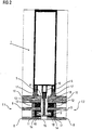
- the FIG. 1 shows the known structure of a glass facade with two-layer glass elements and visible on the front pressure bars, for connecting the glass elements with the support frame.
- the support frame 1 in the form of a post with front-mounted webs 5 and 6, wherein in the edge-side webs 5 sealing strips 17 are mounted, which are supported against the glass elements 7.1 and 7.2.
- the glass elements are connected by a pressure bar 2 via a screw 4 with the central web 6 of the post 1, wherein the pressure bar 2 to the glass elements 7.1 and 7.2, a seal 19 which also prevents damage to the glass elements and acts as a weather seal.
- the glass elements 7.1 and 7.2 consist of a frame-side glass pane 9, which is designed here as a laminated glass pane, and a front glass pane 8. Between the glass sheets 8 and 9, a spacer 11 is introduced with a silicone composite 13 respectively.
- FIGS. 2 to 4 An improved embodiment is in the inventive structure of FIGS. 2 to 4 shown.
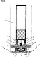
- FIG. 2 shows a section through a fire-retardant glass facade in the region of a post 1, wherein the abutting glass elements 7.1 and 7.2 of the glass facade are constructed in three layers with the glass layers 8, 9 and 10.
- the glass elements abut, sealed by the sealing elements 17, without the use of an adapter system directly to the support structure 1 at.
- the glass elements 7.1 and 7.2 are constructed by a frame-side refractory glass pane 10, which follows an approximately half as thin glass sheet 9, spaced by a spacer element 12, wherein edge of a first silicone composite 13 is poured between the two glass sheets 10 and 9. This is followed by the front glass pane 8, which is also spaced from the central glass pane 9 by a slightly larger spacing element 11 and also has a silicone composite 14 at the edge. In the silicone composite 14, a U-shaped engagement profile is cast, the open side facing the edge of the glass element.
- FIG. 3 Another embodiment of the invention is in the FIG. 3 shown. This corresponds basically to the execution of the FIG. 2
- another engagement profile is additionally arranged in the frame-side glass composite, so that, for example, alternately anchor elements in the frame-side and front-side engagement element can be screwed, whereby an attachment is generated, which is distributed over a plurality of engagement elements.
- FIG. 4 a particularly simple embodiment of a fire-retardant glass wall with a compound according to the invention of the glass elements to the support frame.
- the execution in the FIG. 4 is similar to the designs in the Figures 2 and 3
- the execution of the glass elements 7.1 and 7.2 is simplified by only two glass panes are used. Accordingly, this is Engagement profile 18 between the two single glass panes, which are spaced apart by spacer elements 11.
- the engagement profile 18 is embedded in the silicone composite 13, so that a solid connection to the support structure 1 can be achieved via a plurality of anchor elements 3.
- glass sheets shown can also be designed as laminated glass panes.
Abstract
Description
Die Erfindung betrifft eine feuerhemmende Glasfassade mit einem Traggerüst bestehend aus metallischen Pfosten und Riegeln, mehreren am Traggerüst befestigten und eine Front bildenden Glaselementen mit einer Front- und einer Gerüstseite, wobei die Glaselemente aus mehrschichtig angeordneten Glasscheiben bestehen und die Befestigung der Glaselemente am Traggerüst durch anschraubbare Ankerelemente vorgesehen ist.The invention relates to a fire-retardant glass facade with a supporting frame consisting of metallic posts and bars, several attached to the support frame and a front forming glass elements with a front and a scaffold side, the glass elements consist of multi-layer glass panes and the attachment of the glass elements on the support frame by bolted Anchoring elements is provided.
Solche Glasfassaden sind allgemein bekannt. Beispielhaft wird auf die "Allgemeine bauaufsichtliche Zulassung", Nr. Z-70.4-50 verwiesen. Derartige Glaswände dienen beispielsweise als Feuerwiderstandsglas, welches durch die raumabschließende Funktion die Ausbreitung von Feuer und Rauch für eine gewisse Zeit verhindern soll. Bei dieser bekannten Ausführung einer Glaswand werden die einzelnen Glaselemente der Glaswand an einer Rahmenkonstruktion mit Pressleisten befestigt.Such glass facades are well known. For example, reference is made to the "General Building Inspectorate Approval", No. Z-70.4-50. Such glass walls are used, for example, as fire resistance glass, which should prevent the propagation of fire and smoke for a certain time by the raumabschließende function. In this known embodiment of a glass wall, the individual glass elements of the glass wall are attached to a frame construction with pressure bars.
Diese feuerhemmenden Glasfassaden haben aufgrund der verwendeten Pressleisten den Nachteil einer aufwendigen Montage und auch hoher Herstellungskosten, außerdem wird der optische Eindruck der Glasfassade durch die dominant nach außen hervortretenden Pressleisten gestört.These fire-retardant glass facades have due to the pressure strips used the disadvantage of a complex installation and high production costs, also the visual impression of the glass facade is disturbed by the dominant outwardly projecting pressure bars.
Es ist Aufgabe der Erfindung, eine konstruktive Lösung für eine solche feuerhemmende Glasfassade zu finden, bei der die beschriebenen Nachteile vermieden werden, ohne jedoch die Stabilität und auch die Feuerschutzfähigkeit der Glasfassade einzuschränken.It is an object of the invention to find a constructive solution for such a fire-retardant glass facade, in which the disadvantages described are avoided, but without limiting the stability and also the fire protection capability of the glass facade.
Diese Aufgabe wird durch die Merkmale der unabhängigen Patentansprüche gelöst. Vorteile der Weiterbildung der Erfindung sind Gegenstand der untergeordneten Ansprüche.This object is solved by the features of the independent claims. Advantages of the development of the invention are the subject of the subordinate claims.
Entsprechend dem Grundgedanken der Erfindung schlägt der Erfinder die Verbesserung einer feuerhemmenden Glasfassade vor, welche ein Traggerüst bestehend aus metallischen Pfosten und Riegeln enthält, mehrere am Traggerüst befestigte und eine Front bildende Glaselemente mit einer Front- und einer Gerüstseite aufweist, wobei die Glaselemente aus mehrschichtig angeordneten Glasscheiben bestehen und die Befestigung der Glaselemente am Traggerüst durch anschraubbare Ankerelemente vorgesehen ist.In accordance with the principles of the invention, the inventor proposes to improve a fire-retardant glass façade comprising a supporting framework consisting of metallic posts and bars, a plurality of glass elements attached to the supporting framework and forming a front with a front and a scaffold side, the glass elements being of multilayered construction Glass panels exist and the attachment of the glass elements is provided on the support frame by bolted anchor elements.
Die erfindungagemäße Verbesserung besteht darin, dass jedes Glaselement mindestens zwei Schichten aufweist, die durch randseitig angeordnete Abstandshalter voneinander beabstandet werden, die beabstandeten Schichten durch einen Isolierglasrandverbund versiegelt sind und im Isolierglasranciverbund ein Eingriffsprofil mit zumindest teilweiser Öffnung zum Rand des Glaselementes angeordnet ist, wobei die am Traggerüst anschraubbaren Ankerelemente in das Eingriffsprofil eingreifen.The erfindungagemäße improvement is that each glass element has at least two layers, which are spaced apart by peripherally arranged spacers, the spaced layers are sealed by a Isolierglasrandverbund and in Isolierglasranciverbund an engagement profile is arranged with at least partial opening to the edge of the glass element, wherein the am Carrying frame bolted anchor elements engage in the engagement profile.
Durch diese erfindungsgemäße Ausgestaltung einer feuerhemmenden Glasfassade wird erreicht, dass auf die im Stand der Technik vorhandenen Pressleisten verzichtet werden kann.This inventive design of a fire-retardant glass facade ensures that it can be dispensed with existing in the prior art pressure bars.
Es ist darauf hinzuweisen, dass der genannte Isolierglasverbund bekannterweise meist auf der Basis von Silikon hergestellt wird, wobei meist brandhemmende Zusätze hinzugefügt werden, die ein verbessertes Verhalten des Silikonverbundes im Brandfalle bewirken.It should be noted that the said insulating glass composite is known to be usually made on the basis of silicone, with mostly fire retardant additives are added, which cause an improved behavior of the silicone composite in case of fire.
In einer besonders vorteilhaften Ausführung kann jedes Glaselement aus mindestens drei Schichten bestehen, die durch randseitig angeordnete Abstandshalter voneinander beabstandet werden. Bei dieser Ausführung kann das Eingriffsprofil sowohl entweder im frontseitigen oder im gerüstseitigen Isolierglasrandverbund angeordnet werden, oder es besteht die Möglichkeit, ein Eingriffsprofil hier in beide, nämlich dem gerüstseitigen und dem frontseitigen Isolierglasrandverbund, einzubauen.In a particularly advantageous embodiment, each glass element may consist of at least three layers, which are spaced apart by spacers arranged at the edge. In this embodiment, the engagement profile can be arranged either in the front or in the frame side insulating glass edge composite, or there is the possibility of an engagement profile here in both, namely the frame side and the front insulating glass edge composite to install.
Weiterhin wird vorgeschlagen, dass das Eingriffsprofil ein teilweise randseitig geöffnetes Hohl-Profil ist, wobei das Eingriffsprofil beispielhaft als rundes Hohl-Profil ausgebildet werden kann oder auch als rechteckiges Hohl-Profil verwirklicht wird.Furthermore, it is proposed that the engagement profile is a partially open at the edge hollow profile, the engagement profile can be exemplified as a round hollow profile or realized as a rectangular hollow profile.
In einer bevorzugten Ausführungsform wird das Eingriffsprofil als zum Rand hin geöffnetes U-Profil ausgeführt, so dass bei der Positionierung der darin eingreifenden Ankerelemente keine Beschränkungen entstehen.In a preferred embodiment, the engagement profile is designed as a U-profile which is open toward the edge, so that no restrictions arise during the positioning of the anchor elements engaging therein.
Vorteilhaft kann weiterhin an der frontseitigen Stoßkante der Glaselemente eine Wetterversiegelung angebracht werden, so dass die gesamte Glasfront als einheitliche Ebene erscheint. Diese Wetterversiegelung kann besonders vorteilhaft aus einer Silikonfüllung bestehen, es ist jedoch auch möglich, anstelle einer Silikonfüllung ein elastisches Profil, beispielsweise ein einzusetzendes Gummi- oder Kunststoffprofil, zu verwenden.Advantageously, a weather seal can be attached to the front edge of the glass elements, so that the entire glass front appears as a single level. This weather seal can be particularly advantageous consist of a silicone filling, but it is also possible to use instead of a silicone filling an elastic profile, for example, a rubber or plastic profile to be used.
Zwischen dem Traggerüst und den Glaselementen können ebenfalls elastische Profile zur Abdichtung mit Brandschutzeigenschaften, beispielsweise aus Kunststoff oder Kautschuk mit entsprechenden chemischen Zusätzen, verwendet werden.Between the support frame and the glass elements also elastic profiles can be used for sealing with fire protection properties, such as plastic or rubber with appropriate chemical additives.
In einer besonders vorteilhaften Ausführungsform kann das Traggerüst auf der Frontseite mindestens einen zentral angeordneten Steg aufweisen, in den die Verschraubung der Ankerelemente eingreifen kann.In a particularly advantageous embodiment, the support frame on the front side may have at least one centrally arranged web, in which the screwing of the anchor elements can engage.
Außerdem kann das Traggerüst auf der Frontseite mindestens zwei randseitig angeordnete Stege zur Aufnahme des elastischen Profils oder einer feuerfesten Dichtung aufweisen.In addition, the support frame on the front side at least two edges arranged webs for receiving the elastic profile or a refractory seal.
Die Ankerelemente können derart ausgebildet werden, dass sie bei der Verschraubung eine lokale Deformation des Eingriffsprofils erzeugen und sich dadurch in dem Eingriffsprofil verhaken. Das heißt, es kann also durch eine entsprechende Formgebung des Ankerelementes derart, dass seine Spitzen zur Gerüstseite zeigen, beim Verschrauben des Ankerelementes ein sicherer Formschluss mit dem Eingriffsprofil erreicht werden.The anchor elements can be designed such that they produce a local deformation of the engagement profile during the screwing and thereby get caught in the engagement profile. That is, it can thus be achieved by a corresponding shape of the anchor element such that its tips to the scaffold side, when screwing the anchor element a secure positive engagement with the engagement profile.
Vorteilhaft ist es weiterhin, wenn die Abstandshalter korrosionsgeschützt ausgeführt werden beziehungsweise aus Edelstahl bestehen. Gleiches gilt ebenso für die verwendeten Anker und Verschraubungen. Hierdurch wird erreicht, dass eine lange sichere Standzeit der Glasfassade auch unter ungünstigen Umweltbedingungen möglich ist.It is also advantageous if the spacers are executed protected against corrosion or consist of stainless steel. The same applies to the anchors and fittings used. This ensures that a long safe life of the glass facade is possible even under unfavorable environmental conditions.
Anstelle einer Vielzahl einzelner Ankerelemente kann auch ein langes Profil, vorzugsweise ein Profil welches über die gesamte Kantenlänge des zu verbindenden Glaselementes reicht, verwendet werden. So entsteht durch dieses zusätzliche Ankerelement oder Ankerprofil eine weitere effektive Abdichtung gegen eventuell auftretende Feuer.Instead of a plurality of individual anchor elements, a long profile, preferably a profile which extends over the entire edge length of the glass element to be joined, can also be used. Thus, this additional anchor element or anchor profile creates a more effective seal against any occurring fire.
Zumindest die gerüstseitige Glasscheibe der Glaselemente kann feuerhemmend ausgeführt werden.At least the frame-side glass pane of the glass elements can be made fire-retardant.
Weiterhin kann die gerüstseitige Glasscheibe eine Dicke aufweisen, die mindestens der Gesamtdicke aller restlichen frontseitig angeordneten Glasscheiben entspricht.Furthermore, the frame-side glass pane may have a thickness which corresponds at least to the total thickness of all remaining front glass panes.
Im folgenden wird die Erfindung anhand der nachfolgenden Figuren näher beschrieben, wobei nur die zum Verständnis der Erfindung notwendigen Merkmale dargestellt sind.In the following the invention will be described in more detail with reference to the following figures, wherein only the features necessary for understanding the invention are shown.
Es zeigen im Einzelnen:
- FIG 1:
- Ausführung einer Glasfassade gemäß dem Stand der Technik;
- FIG 2:
- Erfindungsgemäßer Aufbau einer Glasfassade mit dreischichtigen Glaselementen;
- FIG 3:
- Erfindungsgemäßer Aufbau einer Glasfassade mit dreischichtigen Glaselementen und zweifachen Eingriffsprofilen;
- FIG 4:
- Erfindungsgemäßer Aufbau einer Glasfassade mit zweischichtigen Glaselementen.
- FIG. 1:
- Execution of a glass facade according to the prior art;
- 2:
- Inventive construction of a glass facade with three-layer glass elements;
- 3
- Inventive construction of a glass facade with three-layer glass elements and double engagement profiles;
- 4:
- Inventive construction of a glass facade with two-layer glass elements.
Die
Ein derartiger Aufbau ist relativ umständlich bei der Montage und erzeugt auch einen optischen Eindruck, der das klare Bild einer glatten Fassade stört.Such a construction is relatively cumbersome to install and also creates a visual impression that disturbs the clear image of a smooth facade.
Eine verbesserte Ausführung wird in dem erfindungsgemäßen Aufbau der
Die
Die Glaselemente stoßen, abgedichtet durch die Dichtelemente 17, ohne die Verwendung eines Adaptersystems direkt an die Tragkonstruktion 1 an. Die Glaselemente 7.1 und 7.2 sind durch eine gerüstseitige feuerfeste Glasscheibe 10, der eine etwa halb so dünne Glasscheibe 9, beabstandet durch ein Abstandselement 12, folgt, aufgebaut, wobei randseitig ein erster Silikonverbund 13 zwischen den beiden Glasscheiben 10 und 9 eingegossen ist. Anschließend folgt die frontseitige Glasscheibe 8, die ebenfalls von der mittleren Glasscheibe 9 durch ein hier etwas größeres Abstandselement 11 beabstandet ist und ebenfalls randseitig über einen Silikonverbund 14 verfügt. In den Silikonverbund 14 ist ein u-förmiges Eingriffsprofil eingegossen, dessen offene Seite zum Rand des Glaselementes weist. In dieses offene U-Profil greift das Ankerelement 3 ein, welches durch eine Schraube 4 mit dem zentralen Steg 6 des Traggerüstes 1 verschraubt wird. Durch eine Vielzahl solcher Ankerelemente 3 über die Kantenlänge der Glaselemente werden diese fest mit dem Traggerüst 1 verbunden, ohne dass ein Adapterelement - wie in der
Eine andere erfindungsgemäße Ausführung ist in der
Schließlich zeigt die
Es wird darauf hingewiesen, dass die gezeigten Glasscheiben auch als Verbundglasscheiben ausgeführt werden können.It should be noted that the glass sheets shown can also be designed as laminated glass panes.
Es versteht sich, dass die vorstehend genannten Merkmale der Erfindung nicht nur in der jeweils angegebenen Kombination, sondern auch in anderen Kombinationen oder in Alleinstellung verwendbar sind, ohne den Rahmen der Erfindung zu verlassen.It is understood that the abovementioned features of the invention can be used not only in the respectively specified combination but also in other combinations or in isolation, without departing from the scope of the invention.
- 11
- Pfosten oder Riegel der TragkonstruktionPost or bar of the supporting structure
- 22
- Pressleistepressure bar
- 33
- Ankerelementanchor member
- 44
- Schraubescrew
- 55
- randseitiger Stegedge-side bridge
- 66
- zentraler Stegcentral pier
- 7.17.1
- Glaselementglass element
- 7.27.2
- Glaselementglass element
- 88th
- erste Scheibefirst disc
- 99
- zweite Scheibesecond disc
- 1010
- dritte Scheibethird disc
- 1111
- erstes Abstandselementfirst spacer element
- 1212
- zweites Abstandselementsecond spacer element
- 1313
- erster Silikonverbundfirst silicone compound
- 1414
- zweiter Silikonverbundsecond silicone compound
- 1515
- WetterversiegelungWeather sealing
- 1616
- Trennelementseparating element
- 1717
- Dichtleistesealing strip
- 1818
- Eingriffsprofilengagement profile
- 1919
- Dichtungpoetry
Claims (22)
dadurch gekennzeichnet, dass
characterized in that
Priority Applications (1)
| Application Number | Priority Date | Filing Date | Title |
|---|---|---|---|
| EP06026251A EP1936096A1 (en) | 2006-12-19 | 2006-12-19 | fire retardant glass-façade |
Applications Claiming Priority (1)
| Application Number | Priority Date | Filing Date | Title |
|---|---|---|---|
| EP06026251A EP1936096A1 (en) | 2006-12-19 | 2006-12-19 | fire retardant glass-façade |
Publications (1)
| Publication Number | Publication Date |
|---|---|
| EP1936096A1 true EP1936096A1 (en) | 2008-06-25 |
Family
ID=37814595
Family Applications (1)
| Application Number | Title | Priority Date | Filing Date |
|---|---|---|---|
| EP06026251A Withdrawn EP1936096A1 (en) | 2006-12-19 | 2006-12-19 | fire retardant glass-façade |
Country Status (1)
| Country | Link |
|---|---|
| EP (1) | EP1936096A1 (en) |
Cited By (6)
| Publication number | Priority date | Publication date | Assignee | Title |
|---|---|---|---|---|
| WO2010085175A1 (en) * | 2009-01-21 | 2010-07-29 | Закрытое Акционерное Общество "Т.Б.М." | Mullion and transom partition frame |
| WO2011140500A1 (en) | 2010-05-07 | 2011-11-10 | Technical Glass Products | Mounting fixture for fire-rated structurally glazed glass |
| ITVR20120054A1 (en) * | 2012-03-22 | 2013-09-23 | Aluk Group S P A | FACADE STRUCTURE FOR BUILDINGS |
| GB2515513A (en) * | 2013-06-26 | 2014-12-31 | Architectural & Metal Systems Ltd | Structural component |
| WO2017005791A1 (en) * | 2015-07-08 | 2017-01-12 | Wall Solutions (Schweiz) Ag | Fire-protection glazing arrangement |
| EP4198246A1 (en) * | 2021-12-20 | 2023-06-21 | Purso Oy | Mounting device for a fastening groove of an insulating glass unit |
Citations (7)
| Publication number | Priority date | Publication date | Assignee | Title |
|---|---|---|---|---|
| EP0130438A2 (en) * | 1983-06-30 | 1985-01-09 | Vision Engineering & Design Inc. | Structural spacer glazing |
| EP0404419A1 (en) * | 1989-06-20 | 1990-12-27 | Environmental Seals Limited | Improvements in or relating to intumescent fire seals and their method of manufacture |
| EP0628672A1 (en) * | 1993-06-08 | 1994-12-14 | Saint Gobain Vitrage International | Insulating glazing for facades |
| GB2296279A (en) * | 1994-12-22 | 1996-06-26 | Glaverbel | Multiple glazing unit with channel-shaped fixing element |
| FR2827322A1 (en) * | 2001-07-13 | 2003-01-17 | Profix Sa | Fastening for double-wall panel to shell of building comprises tubular deformable member with end thrust elements and plugs to produce rigidity |
| EP1335079A1 (en) * | 2002-02-11 | 2003-08-13 | Reynolds Architectuursystemen | Wall panel, method for manufacturing same and use of the panel in a curtain wall |
| EP1493895A2 (en) * | 2003-06-30 | 2005-01-05 | Zhuhai King Glass Engineering Co. Ltd. | A device for fixing glasses on a curtain wall or roofing |
-
2006
- 2006-12-19 EP EP06026251A patent/EP1936096A1/en not_active Withdrawn
Patent Citations (7)
| Publication number | Priority date | Publication date | Assignee | Title |
|---|---|---|---|---|
| EP0130438A2 (en) * | 1983-06-30 | 1985-01-09 | Vision Engineering & Design Inc. | Structural spacer glazing |
| EP0404419A1 (en) * | 1989-06-20 | 1990-12-27 | Environmental Seals Limited | Improvements in or relating to intumescent fire seals and their method of manufacture |
| EP0628672A1 (en) * | 1993-06-08 | 1994-12-14 | Saint Gobain Vitrage International | Insulating glazing for facades |
| GB2296279A (en) * | 1994-12-22 | 1996-06-26 | Glaverbel | Multiple glazing unit with channel-shaped fixing element |
| FR2827322A1 (en) * | 2001-07-13 | 2003-01-17 | Profix Sa | Fastening for double-wall panel to shell of building comprises tubular deformable member with end thrust elements and plugs to produce rigidity |
| EP1335079A1 (en) * | 2002-02-11 | 2003-08-13 | Reynolds Architectuursystemen | Wall panel, method for manufacturing same and use of the panel in a curtain wall |
| EP1493895A2 (en) * | 2003-06-30 | 2005-01-05 | Zhuhai King Glass Engineering Co. Ltd. | A device for fixing glasses on a curtain wall or roofing |
Cited By (9)
| Publication number | Priority date | Publication date | Assignee | Title |
|---|---|---|---|---|
| WO2010085175A1 (en) * | 2009-01-21 | 2010-07-29 | Закрытое Акционерное Общество "Т.Б.М." | Mullion and transom partition frame |
| WO2011140500A1 (en) | 2010-05-07 | 2011-11-10 | Technical Glass Products | Mounting fixture for fire-rated structurally glazed glass |
| EP2567040A1 (en) * | 2010-05-07 | 2013-03-13 | Technical Glass Products | Mounting fixture for fire-rated structurally glazed glass |
| US8567142B2 (en) | 2010-05-07 | 2013-10-29 | Dustin D. Swartz | Mounting fixture for fire-rated structurally glazed glass |
| EP2567040A4 (en) * | 2010-05-07 | 2014-12-03 | Technical Glass Products | Mounting fixture for fire-rated structurally glazed glass |
| ITVR20120054A1 (en) * | 2012-03-22 | 2013-09-23 | Aluk Group S P A | FACADE STRUCTURE FOR BUILDINGS |
| GB2515513A (en) * | 2013-06-26 | 2014-12-31 | Architectural & Metal Systems Ltd | Structural component |
| WO2017005791A1 (en) * | 2015-07-08 | 2017-01-12 | Wall Solutions (Schweiz) Ag | Fire-protection glazing arrangement |
| EP4198246A1 (en) * | 2021-12-20 | 2023-06-21 | Purso Oy | Mounting device for a fastening groove of an insulating glass unit |
Similar Documents
| Publication | Publication Date | Title |
|---|---|---|
| EP1936096A1 (en) | fire retardant glass-façade | |
| DE29825035U1 (en) | wall cassette | |
| DE20221887U1 (en) | Modular system for producing a fire protection component as well as fire protection component produced therewith | |
| DE102009023883A1 (en) | Facade element for use in post- and beam constructions in building, has filling element firmly connected with beam and post elements forming carrier structure by aluminum profiles and thermal separation element | |
| EP3060725B1 (en) | Breakage-resistant composite material and stud wall, roof or ceiling structure | |
| DE102008011207A1 (en) | Building completion in blast resistant design | |
| EP2372032B1 (en) | Partition wall made of transparent wall elements | |
| AT514271B1 (en) | door | |
| EP1944429A1 (en) | Inspection cover | |
| EP2500501A2 (en) | Frame assembly with at least one frame connection element | |
| DE102010032947B4 (en) | Attachment construction for mullion and transom elements with improved thermal insulation properties | |
| DE102004016215B4 (en) | Mullion-transom system with low view width | |
| DE202014101050U1 (en) | insulating glass pane | |
| DE102019213918A1 (en) | Door with paneling | |
| EP2394905B1 (en) | A support profile for a construction board | |
| EP2572055A1 (en) | Burglar-proof wall | |
| DE102005001613A1 (en) | Fire protection wall for public buildings comprises a post-bar construction consisting of profiles separated by a fire protection layer with hollow chambers arranged in the profiles for insertion of devices | |
| EP1319790A2 (en) | Anchor for door and window | |
| DE102015201675A1 (en) | Door or window system | |
| EP3770372A1 (en) | Box for holding a roller shutter or a sunshade and window or door | |
| CH707540A2 (en) | Supporting glass wall element for lightweight constructions. | |
| DE102007053659A1 (en) | Building facade for acting as a fire-protection facade has a framed structure made from uprights and bars as well as from glazing elements/cladding enclosed by the uprights and bars | |
| DE7414512U (en) | Device for fixing door frames and the like | |
| DE202005020867U1 (en) | Glazed fire protection wall comprising filled, post-and-transom framework, includes metal profile posts with intumescent strips and provisions for electronic equipment | |
| CH656180A5 (en) | BULLETPROOF FRAME COMPOSED OF PROFILES. |
Legal Events
| Date | Code | Title | Description |
|---|---|---|---|
| PUAI | Public reference made under article 153(3) epc to a published international application that has entered the european phase |
Free format text: ORIGINAL CODE: 0009012 |
|
| AK | Designated contracting states |
Kind code of ref document: A1 Designated state(s): AT BE BG CH CY CZ DE DK EE ES FI FR GB GR HU IE IS IT LI LT LU LV MC NL PL PT RO SE SI SK TR |
|
| AX | Request for extension of the european patent |
Extension state: AL BA HR MK RS |
|
| AKX | Designation fees paid | ||
| STAA | Information on the status of an ep patent application or granted ep patent |
Free format text: STATUS: THE APPLICATION IS DEEMED TO BE WITHDRAWN |
|
| 18D | Application deemed to be withdrawn |
Effective date: 20081230 |
|
| REG | Reference to a national code |
Ref country code: DE Ref legal event code: 8566 |