EP1936017B1 - Method and device for manufacturing a spunbonding fabric made of cellulose filaments - Google Patents
Method and device for manufacturing a spunbonding fabric made of cellulose filaments Download PDFInfo
- Publication number
- EP1936017B1 EP1936017B1 EP06026730.9A EP06026730A EP1936017B1 EP 1936017 B1 EP1936017 B1 EP 1936017B1 EP 06026730 A EP06026730 A EP 06026730A EP 1936017 B1 EP1936017 B1 EP 1936017B1
- Authority
- EP
- European Patent Office
- Prior art keywords
- filaments
- cooling
- air
- cellulose
- diffuser
- Prior art date
- Legal status (The legal status is an assumption and is not a legal conclusion. Google has not performed a legal analysis and makes no representation as to the accuracy of the status listed.)
- Active
Links
- 238000000034 method Methods 0.000 title claims description 48
- 229920002678 cellulose Polymers 0.000 title claims description 41
- 239000001913 cellulose Substances 0.000 title claims description 41
- 238000004519 manufacturing process Methods 0.000 title claims description 5
- 239000004744 fabric Substances 0.000 title claims 4
- 238000001816 cooling Methods 0.000 claims description 106
- 239000003570 air Substances 0.000 claims description 70
- 239000012736 aqueous medium Substances 0.000 claims description 20
- 239000012080 ambient air Substances 0.000 claims description 17
- 230000008021 deposition Effects 0.000 claims description 13
- XLYOFNOQVPJJNP-UHFFFAOYSA-N water Substances O XLYOFNOQVPJJNP-UHFFFAOYSA-N 0.000 claims description 13
- 230000015271 coagulation Effects 0.000 claims description 11
- 238000005345 coagulation Methods 0.000 claims description 11
- 239000000203 mixture Substances 0.000 claims description 7
- 150000003512 tertiary amines Chemical class 0.000 claims description 6
- 239000000126 substance Substances 0.000 claims description 5
- 229920000433 Lyocell Polymers 0.000 claims description 4
- 230000001737 promoting effect Effects 0.000 claims 1
- 239000000243 solution Substances 0.000 description 20
- 239000004745 nonwoven fabric Substances 0.000 description 11
- LFTLOKWAGJYHHR-UHFFFAOYSA-N N-methylmorpholine N-oxide Chemical compound CN1(=O)CCOCC1 LFTLOKWAGJYHHR-UHFFFAOYSA-N 0.000 description 8
- 238000003860 storage Methods 0.000 description 8
- 238000005406 washing Methods 0.000 description 7
- 239000000835 fiber Substances 0.000 description 5
- 239000007921 spray Substances 0.000 description 5
- 239000007864 aqueous solution Substances 0.000 description 4
- 238000000151 deposition Methods 0.000 description 4
- 230000001112 coagulating effect Effects 0.000 description 2
- 238000001035 drying Methods 0.000 description 2
- 239000007789 gas Substances 0.000 description 2
- 238000002347 injection Methods 0.000 description 2
- 239000007924 injection Substances 0.000 description 2
- 239000007788 liquid Substances 0.000 description 2
- 230000001105 regulatory effect Effects 0.000 description 2
- 230000007704 transition Effects 0.000 description 2
- 238000009489 vacuum treatment Methods 0.000 description 2
- 238000005299 abrasion Methods 0.000 description 1
- 238000006065 biodegradation reaction Methods 0.000 description 1
- 238000000354 decomposition reaction Methods 0.000 description 1
- 230000018044 dehydration Effects 0.000 description 1
- 238000006297 dehydration reaction Methods 0.000 description 1
- 230000003111 delayed effect Effects 0.000 description 1
- 238000000605 extraction Methods 0.000 description 1
- 238000001914 filtration Methods 0.000 description 1
- 239000003595 mist Substances 0.000 description 1
- 239000000178 monomer Substances 0.000 description 1
- 230000000704 physical effect Effects 0.000 description 1
- 229920000642 polymer Polymers 0.000 description 1
- 238000011084 recovery Methods 0.000 description 1
- 238000009987 spinning Methods 0.000 description 1
Images

Classifications
-
- D—TEXTILES; PAPER
- D04—BRAIDING; LACE-MAKING; KNITTING; TRIMMINGS; NON-WOVEN FABRICS
- D04H—MAKING TEXTILE FABRICS, e.g. FROM FIBRES OR FILAMENTARY MATERIAL; FABRICS MADE BY SUCH PROCESSES OR APPARATUS, e.g. FELTS, NON-WOVEN FABRICS; COTTON-WOOL; WADDING ; NON-WOVEN FABRICS FROM STAPLE FIBRES, FILAMENTS OR YARNS, BONDED WITH AT LEAST ONE WEB-LIKE MATERIAL DURING THEIR CONSOLIDATION
- D04H3/00—Non-woven fabrics formed wholly or mainly of yarns or like filamentary material of substantial length
- D04H3/08—Non-woven fabrics formed wholly or mainly of yarns or like filamentary material of substantial length characterised by the method of strengthening or consolidating
- D04H3/16—Non-woven fabrics formed wholly or mainly of yarns or like filamentary material of substantial length characterised by the method of strengthening or consolidating with bonds between thermoplastic filaments produced in association with filament formation, e.g. immediately following extrusion
-
- D—TEXTILES; PAPER
- D04—BRAIDING; LACE-MAKING; KNITTING; TRIMMINGS; NON-WOVEN FABRICS
- D04H—MAKING TEXTILE FABRICS, e.g. FROM FIBRES OR FILAMENTARY MATERIAL; FABRICS MADE BY SUCH PROCESSES OR APPARATUS, e.g. FELTS, NON-WOVEN FABRICS; COTTON-WOOL; WADDING ; NON-WOVEN FABRICS FROM STAPLE FIBRES, FILAMENTS OR YARNS, BONDED WITH AT LEAST ONE WEB-LIKE MATERIAL DURING THEIR CONSOLIDATION
- D04H3/00—Non-woven fabrics formed wholly or mainly of yarns or like filamentary material of substantial length
- D04H3/013—Regenerated cellulose series
-
- B—PERFORMING OPERATIONS; TRANSPORTING
- B29—WORKING OF PLASTICS; WORKING OF SUBSTANCES IN A PLASTIC STATE IN GENERAL
- B29C—SHAPING OR JOINING OF PLASTICS; SHAPING OF MATERIAL IN A PLASTIC STATE, NOT OTHERWISE PROVIDED FOR; AFTER-TREATMENT OF THE SHAPED PRODUCTS, e.g. REPAIRING
- B29C48/00—Extrusion moulding, i.e. expressing the moulding material through a die or nozzle which imparts the desired form; Apparatus therefor
- B29C48/03—Extrusion moulding, i.e. expressing the moulding material through a die or nozzle which imparts the desired form; Apparatus therefor characterised by the shape of the extruded material at extrusion
- B29C48/05—Filamentary, e.g. strands
-
- B—PERFORMING OPERATIONS; TRANSPORTING
- B29—WORKING OF PLASTICS; WORKING OF SUBSTANCES IN A PLASTIC STATE IN GENERAL
- B29C—SHAPING OR JOINING OF PLASTICS; SHAPING OF MATERIAL IN A PLASTIC STATE, NOT OTHERWISE PROVIDED FOR; AFTER-TREATMENT OF THE SHAPED PRODUCTS, e.g. REPAIRING
- B29C48/00—Extrusion moulding, i.e. expressing the moulding material through a die or nozzle which imparts the desired form; Apparatus therefor
- B29C48/25—Component parts, details or accessories; Auxiliary operations
- B29C48/92—Measuring, controlling or regulating
-
- D—TEXTILES; PAPER
- D01—NATURAL OR MAN-MADE THREADS OR FIBRES; SPINNING
- D01D—MECHANICAL METHODS OR APPARATUS IN THE MANUFACTURE OF ARTIFICIAL FILAMENTS, THREADS, FIBRES, BRISTLES OR RIBBONS
- D01D5/00—Formation of filaments, threads, or the like
- D01D5/12—Stretch-spinning methods
- D01D5/14—Stretch-spinning methods with flowing liquid or gaseous stretching media, e.g. solution-blowing
-
- D—TEXTILES; PAPER
- D01—NATURAL OR MAN-MADE THREADS OR FIBRES; SPINNING
- D01F—CHEMICAL FEATURES IN THE MANUFACTURE OF ARTIFICIAL FILAMENTS, THREADS, FIBRES, BRISTLES OR RIBBONS; APPARATUS SPECIALLY ADAPTED FOR THE MANUFACTURE OF CARBON FILAMENTS
- D01F2/00—Monocomponent artificial filaments or the like of cellulose or cellulose derivatives; Manufacture thereof
-
- D—TEXTILES; PAPER
- D04—BRAIDING; LACE-MAKING; KNITTING; TRIMMINGS; NON-WOVEN FABRICS
- D04H—MAKING TEXTILE FABRICS, e.g. FROM FIBRES OR FILAMENTARY MATERIAL; FABRICS MADE BY SUCH PROCESSES OR APPARATUS, e.g. FELTS, NON-WOVEN FABRICS; COTTON-WOOL; WADDING ; NON-WOVEN FABRICS FROM STAPLE FIBRES, FILAMENTS OR YARNS, BONDED WITH AT LEAST ONE WEB-LIKE MATERIAL DURING THEIR CONSOLIDATION
- D04H3/00—Non-woven fabrics formed wholly or mainly of yarns or like filamentary material of substantial length
- D04H3/015—Natural yarns or filaments
-
- D—TEXTILES; PAPER
- D04—BRAIDING; LACE-MAKING; KNITTING; TRIMMINGS; NON-WOVEN FABRICS
- D04H—MAKING TEXTILE FABRICS, e.g. FROM FIBRES OR FILAMENTARY MATERIAL; FABRICS MADE BY SUCH PROCESSES OR APPARATUS, e.g. FELTS, NON-WOVEN FABRICS; COTTON-WOOL; WADDING ; NON-WOVEN FABRICS FROM STAPLE FIBRES, FILAMENTS OR YARNS, BONDED WITH AT LEAST ONE WEB-LIKE MATERIAL DURING THEIR CONSOLIDATION
- D04H3/00—Non-woven fabrics formed wholly or mainly of yarns or like filamentary material of substantial length
- D04H3/02—Non-woven fabrics formed wholly or mainly of yarns or like filamentary material of substantial length characterised by the method of forming fleeces or layers, e.g. reorientation of yarns or filaments
-
- B—PERFORMING OPERATIONS; TRANSPORTING
- B29—WORKING OF PLASTICS; WORKING OF SUBSTANCES IN A PLASTIC STATE IN GENERAL
- B29C—SHAPING OR JOINING OF PLASTICS; SHAPING OF MATERIAL IN A PLASTIC STATE, NOT OTHERWISE PROVIDED FOR; AFTER-TREATMENT OF THE SHAPED PRODUCTS, e.g. REPAIRING
- B29C2948/00—Indexing scheme relating to extrusion moulding
- B29C2948/92—Measuring, controlling or regulating
- B29C2948/92504—Controlled parameter
- B29C2948/92704—Temperature
Definitions
- the invention relates to a method for producing a spunbonded cellulosic filaments or fibers, wherein the filaments are spun from a cellulose solution by means of a spinnerette.
- the invention further relates to a device for carrying out the method according to the invention.
- Cellulosic filaments thus means filaments which are spun from a cellulose solution and which consequently are cellulose-containing.
- the invention is based on the technical problem of providing a method of the type mentioned, can be produced with the spunbonded cellulosic filaments that are readily biodegradable, which have a high absorbency and nonetheless show optimal strength properties. Furthermore, the invention is based on the technical problem of specifying a device for carrying out the method according to the invention.
- the invention teaches a method for producing a spunbonded cellulosic filaments or fibers, wherein the filaments are spun from a cellulose solution by means of a spinnerette, wherein the cellulosic filaments are then introduced after exiting the spinnerette in a cooling chamber of at least two cooling sections and wherein the filaments in the two cooling sections in each case with process air or cooling air of different amount and / or different temperature and / or different humidity are brought into contact.
- - Amount of process air or cooling air means in particular the volume flow of the incoming air.
- the at least two cooling sections are arranged one behind the other or one above the other in the direction of movement of the filaments.
- first cooling section is meant here and below the cooling section of the cooling chamber into which the filaments enter first.
- second cooling section means the cooling section into which the filaments enter after the first cooling section.
- the first cooling section is arranged above or vertically above the second cooling section.
- the spinnerette is arranged above or vertically above the first cooling section.
- the cellulosic filaments are spun as lyocell filaments.
- Lyocell filaments mean filaments spun from a solution of cellulose in a mixture of water and an organic substance. It is within the scope of the invention that a solution of cellulose in a mixture of water and a tertiary amine oxide is used as the cellulose solution. The tertiary amine oxide is then the above-mentioned organic Substance.
- the tertiary amine oxide used is preferably N-methylmorpholine N-oxide (NMMO).
- a preferred embodiment of the invention is characterized in that the concentration of the cellulose in the cellulose solution is 0.5 to 25 wt .-%, preferably 1 to 22 wt .-%.
- the concentration of the cellulose is preferably 1.5 to 21 wt .-%, very preferably 2 to 20 wt .-%.
- the amount of air supplied to the first cooling section is less than the amount of air supplied to the second cooling section.
- the ratio of the amount of air supplied to the first cooling section to the amount of air supplied to the second cooling section is 1:10 to 1: 1, preferably 1.5: 10 to 6:10 and preferably 1.5: 10 to 4 , 5: 10th
- the temperature of the cooling air entering the first cooling section is higher than the temperature of the cooling air entering the second cooling section.
- the temperature of the cooling air supplied to the first cooling section is 18 to 80 ° C and the temperature of the cooling air supplied to the second cooling section is 18 to 35 ° C.
- the air humidity of the cooling air entering the two cooling sections is between 60 and 100% relative humidity.
- the humidity of these supplied in these cooling sections cooling air corresponds at least to the moisture that is sucked from the ambient air. It is also within the scope of the invention that mist (relative humidity> 100%) is introduced into the first cooling section and / or into the second cooling section.
- the filaments are aerodynamically stretched after cooling in the cooling chamber and then stored on a storage device.
- the aerodynamic stretching is expediently carried out in a drawing unit downstream of the cooling chamber.
- the storage is preferably carried out on a storage screen belt.
- a particularly preferred embodiment of the invention is characterized in that the filaments are treated prior to deposition on the storage device with the proviso that at least partially coagulation of the cellulose of the filaments takes place.
- This treatment of the filaments to produce coagulation is preferably carried out after aerodynamic stretching and before deposition.
- the treatment is expediently carried out with an aqueous medium, in particular with water and / or steam and / or with an aqueous solution and / or with an aqueous mixture.
- Aqueous solution means above all the solution of an organic substance in water, preferably an aqueous NMMO solution.
- the treatment is carried out with the aqueous medium as a spray treatment, wherein suitably corresponding spray heads or water atomizers are used. It will be explained in more detail below at which points of the device according to the invention the treatment of the filaments described above preferably takes place.
- a particularly preferred embodiment of the method according to the invention is characterized in that after the deposition of the filaments, the formed nonwoven web is treated or washed with an aqueous medium and then dehydrated.
- aqueous medium means in particular water and / or water vapor and / or an aqueous solution and / or an aqueous mixture.
- water or an aqueous NMMO solution is used as the aqueous medium or as the washing liquid used.
- the nonwoven web is then treated / washed on the Ablagesiebband or on the Ablagesiebband downstream band or sieve belt with the aqueous medium. It is within the scope of the invention that the nonwoven web is dewatered after such a washing treatment.
- the dewatering is expediently carried out as a vacuum treatment in a vacuum station and / or by squeezing the nonwoven web in a squeezing unit.
- the nonwoven web is repeatedly treated with the aqueous medium and then each dehydrated.
- the treatment with the aqueous medium and the subsequent dehydration takes place at least three times.
- nonwoven web After the final treatment by washing and dewatering it is recommended to dry the nonwoven web and then expediently to wind up the nonwoven web. It is also within the scope of the invention that the nonwoven web is solidified prior to drying to adjust certain nonwoven web properties and indeed according to a preferred embodiment by hydroentanglement. In addition, before the drying of the nonwoven web to produce certain nonwovens properties, finishes can also be applied to the nonwoven web.
- the invention further teaches a device for carrying out the method according to the invention, with a spinnerette, a cooling chamber, a drawing unit and a storage device, with the spinnerette filaments of a cellulose solution are spinnable, wherein the cooling chamber in at least two cooling sections is divided, in which the filaments with process or cooling air of different amount and / or different temperature and / or different humidity are acted upon.
- the apparatus comprises a cellulose solution supply device with which the cellulose solution is supplied to the spinnerette.
- the spinnerette has a hole density of 0.5 to 9 hole / cm 2 , preferably from 1 to 8 hole / cm 2 and preferably from 1.5 to 7.5 hole / cm 2 .
- By hole is meant an opening in the spinnerette or in the nozzle plate of the spinnerette, through which a filament emerges.
- the hole diameter is suitably 0.1 to 1 mm.
- the holes or the associated holes are arranged evenly distributed in the nozzle plate.
- the bores may be distributed such that a hole density increasing from the center of the nozzle plate to the outside results. But it is also possible that the hole density drops from the center of the nozzle plate to the outside.
- the cooling chamber is arranged at a distance from the spinnerette or to the nozzle plate of the spinnerette.
- a monomer suction device is arranged between the nozzle plate and the cooling chamber.
- the Monomerabsaugungsvoriques sucks air from the Filament Siegsraum directly below the nozzle plate. As a result, the exiting with the filaments gases, especially decomposition products and the like are removed from the plant. It should also be emphasized that with the Monomerabsaugungsvoriques the air flow below the nozzle plate can be controlled in an advantageous manner.
- the cooling chamber is connected via an intermediate channel with a Unterziehkanal, said Unterziehkanal forms the stretching unit of the device.
- a particularly preferred embodiment of the invention is characterized in that the connection or the transition region between the cooling chamber and the intermediate channel is closed to the outside or outwardly free of air supply. Expediently takes place in the entire region of the cooling chamber, the intermediate channel and the Unterziehkanals only a supply of process or cooling air in the cooling chamber and otherwise no air supply from the outside.
- the intermediate channel runs from the outlet of the cooling chamber to the inlet of the Unterziehkanals in a vertical section wedge-shaped. It is within the scope of the invention that the intermediate channel to the entrance of the Unterziehkanals converges in a vertical section to the inlet width of the Unterziehkanals wedge-shaped. It is recommended that different pitch angles of this intermediate channel are adjustable.
- the geometry of the intermediate channel is variable with the proviso that the air velocity can be increased. In this way undesirable, occurring at high temperatures relaxations of the filaments can be avoided.
- a laying unit with at least one diffuser is arranged between the stretching unit (underrun channel) and the depositing device.
- the laying unit consists of a first diffuser and an adjoining second diffuser.
- an ambient air inlet gap is preferably provided between the first and the second diffuser.
- the filaments are treated via this ambient air inlet gap with the proviso that coagulation of the cellulose takes place.
- an aqueous medium preferably water and / or a aqueous solution of NMMO injected.
- spray heads are arranged, via which the aqueous medium can be injected in the direction of the filaments.
- aqueous medium for coagulation is introduced via openings in the diffuser wall or in the diffuser walls.
- spray heads are then integrated into the diffuser wall or into the diffuser walls, via which the aqueous medium can be injected in the direction of the filaments. This injection through openings in the diffuser wall or in the diffuser walls can be done in addition to the injection via the ambient air inlet gap.
- the storage device has at least one continuously moving Ablagesiebband for the spunbonded web.
- At least one suction device is expediently provided underneath this filing screen belt, with which air is drawn through the filing screen belt.
- the suction device is a suction fan which can be controlled and / or regulated.
- the invention is based on the finding that with the method according to the invention and with the device according to the invention, spunbonded nonwovens of cellulosic filaments can be produced, which are distinguished by optimum mechanical properties, in particular by very good strength properties.
- the spunbonded nonwoven fabrics produced according to the invention have a relatively high resistance to abrasion and other mechanical influences. Nonetheless, these spunbonded nonwovens of cellulosic fibers are relatively simple and can be produced with little effort.
- the nonwovens produced according to the invention have a high absorbency and can be used particularly advantageously in hygiene products. Furthermore, the spunbonded nonwovens produced according to the invention are easily biodegradable, so that they are especially compostable as disposable items.
- the spunbonded nonwovens are produced from the cellulosic fibers by the Reicofil IV process.
- This Reicofil IV method is described in EP 1 340 843 A1 described in detail.
- all the features described there can also be used in the present inventive method or in the present device according to the invention.
- particular importance is attached initially to the division of the cooling chamber into at least two cooling sections.
- the cooling chamber, intermediate channel and stretching unit are designed as a closed system in which an air supply takes place only as a process or cooling air supply in the cooling chamber and otherwise preferably no air supply takes place from the outside.
- the division of the laying unit in at least two diffusers, wherein an ambient air inlet gap is provided, through which expediently an aqueous medium for coagulating the cellulose is injected.
- the figures show an apparatus for producing a spunbonded cellulosic filaments.
- the filaments are spun from a cellulose solution by means of a spinnerette 1.
- the cellulose solution is added the spinnerette 1 from an in Fig. 1 supplied only schematically illustrated cellulose solution supply device Z.
- the cellulosic filaments are introduced after exiting the spinnerette 1 in a cooling chamber 2, in which the filaments come into contact with process or cooling air.
- To the cooling chamber 2 closes the intermediate channel 3 and after the intermediate channel 3 follows the Unterziehkanal 5 as drawing unit 4.
- the Unterziehkanal 5 includes the laying unit 6 and below the laying unit 6, the storage device in the form of a continuously moving Ablagesiebbandes 7 for filing the filaments intended for nonwoven web.
- the filaments are preferably and in the embodiment spun as lyocell filaments.
- a solution of cellulose in a mixture of water and a tertiary amine oxide is used as the cellulose solution.
- the tertiary amine oxide is preferably NMMO.
- the concentration of the cellulose in the solution is expediently 2 to 19 wt .-%.
- a Monomerabsaugungs owned 11 is arranged with the occurring during the spinning process disturbing gases can be removed from the plant.
- the extraction is carried out expediently with the proviso that disturbing turbulence between the nozzle plate 10 and the Monomerabsaugung 11 be avoided.
- the cooling chamber 2 is divided in the embodiment into two cooling sections 2a and 2b.
- an air supply cabin 8 is arranged, which is divided into an upper cabin section 8a and a lower cabin section 8b.
- process air cooling air
- process air of different temperature can be supplied from the two cabin sections 8a, 8b.
- process air having a temperature between 18 ° C. and 80 ° C. enters the cooling chamber 2 or the first upper cooling section 2 a from the upper cabin section 8 a.
- process air having a temperature between 18 ° C and 35 ° C enters the cooling chamber 2 or the second lower cooling section 2b from the lower cabin section 8b.
- the process air exiting from the upper cabin section 8a has a higher temperature than the process air exiting from the lower cabin section 8b.
- the process air leaving the upper cabin section 8a may have a lower temperature than the process air leaving the lower cabin section 8b to set particular conditions.
- a fan 9a, 9b for supplying process air is connected to the cabin sections 8a, 8b.
- the quantities or the volume flows of the air supplied to the cooling sections 2a, 2b are different and preferably controllable. It is furthermore within the scope of the invention that the temperature of the respective process air supplied to the cooling sections 2a, 2b can be regulated.
- the intermediate channel 3 converges in a wedge shape from the outlet of the cooling chamber 2 to the inlet of the lower 5 in vertical section and expediently and in the embodiment of the inlet width of the lower channel 5.
- different pitch angle of the intermediate channel 3 are adjustable.
- the lower channel 5 runs towards the laying unit 6 in a vertical section in a wedge shape.
- the channel width of the Unterziehkanals is adjustable. After the aerodynamic stretching in the drawing unit 4 (underpass 5), the filaments enter the laying unit 6.
- the laying unit 6 consists of a first diffuser 13 and an adjoining second diffuser 14. Between the first diffuser 13 and the second diffuser 14, an ambient air inlet gap 15 is provided.
- the filaments passing through the laying unit 6 are treated by the ambient air inlet gap 15 with the proviso that coagulation of the cellulose takes place. This is indicated in the figures by the arrows 12.
- an aqueous medium is injected through the ambient air inlet gap 15 to coagulate the cellulose.
- spray heads in the region of the ambient air inlet gap 15 are present.
- the coagulation-promoting substances can also be injected through corresponding openings in the walls of the diffuser 14. This is not shown in the figures. Appropriately, an aqueous medium for coagulating the cellulose is also injected here.
- each diffuser 13, 14 has an upper converging part and a lower diverging part. Consequently, each diffuser 13, 14 has a narrowest point between the upper converging part and the lower one divergent part.
- the first diffuser 13 has a diverging region 18, whose side walls 16, 17 are adjustable in the manner of a flap. In this way, an opening angle ⁇ of the diverging area 18 can be adjusted.
- the width of the ambient air inlet gap 15 is suitably adjustable.
- the opening angle ⁇ of the second diffuser 14 is continuously adjustable. It is also recommended that the second diffuser 14 is adjusted in height, so that the distance a of the second diffuser 14 can be adjusted to the Ablagesiebband 7. Basically, all the two diffusers 13, 14 and their adjustment features are related to the Reicofil IV method in EP 1 340 843 A1 are described, also in the claimed device according to the invention feasible.
- the aggregate of cooling chamber 2, intermediate channel 3, lower duct 5 and laying unit 6, apart from the air supply in the cooling chamber 2 and the air inlet at the ambient air inlet gap 15 is formed as a closed system. This means that expediently otherwise no air supply from the outside into this unit and in particular not between the cooling chamber 2 and the intermediate channel 3 and not between the intermediate channel 3 and lower channel 5 takes place.
- the emerging from the laying unit 6 filaments are stored to the nonwoven web on the Ablagesiebband 7.
- a suction device 19 Under this air and water-permeable Ablagesiebband 7 is preferably and in the embodiment, a suction device 19, the air and washing liquid from below through the Filtration screen belt 7 sucks.
- the nonwoven web deposited on the storage screen belt 7 is subsequently passed through a washing station 16, in which the nonwoven web is washed with an aqueous medium.
- This aqueous medium is preferably water and / or an aqueous NMMO solution or a mixture of water and NMMO.
- the nonwoven web is passed through a dewatering station 17, in which a dewatering of the nonwoven web takes place.
- the dewatering may take place by vacuum treatment and / or squeezing in a squeeze. It is within the scope of the invention that the nonwoven web is then washed again in another washing station 16 and then dewatered in a further dewatering station 17, this process (washing and dewatering) preferably being repeated at least three times. Thereafter, the nonwoven web is expediently dried and wound according to a preferred embodiment.
Description
Die Erfindung betrifft ein Verfahren zur Herstellung eines Spinnvlieses aus cellulosischen Filamenten bzw. Fasern, wobei die Filamente aus einer Cellulose-Lösung mittels einer Spinnerette ersponnen werden. Die Erfindung betrifft fernerhin eine Vorrichtung zur Durchführung des erfindungsgemäßen Verfahrens. - Cellulosische Filamente meint also Filamente, die aus einer Cellulose-Lösung ersponnen werden und die folglich cellulosehaltig sind.The invention relates to a method for producing a spunbonded cellulosic filaments or fibers, wherein the filaments are spun from a cellulose solution by means of a spinnerette. The invention further relates to a device for carrying out the method according to the invention. Cellulosic filaments thus means filaments which are spun from a cellulose solution and which consequently are cellulose-containing.
Aus der Praxis sind Verfahren zur Herstellung kardierter Vliese aus cellulosischen Filamenten bekannt. Diese Vliese aus cellulosischen Filamenten haben gegenüber Spinnvliesen aus Kunststofffilamenten den Vorteil, dass sie relativ leicht biologisch abbaubar sind. Außerdem sind Vliese aus cellulosischen Filamenten aufgrund ihrer verhältnismäßig hohen Saugfähigkeit in Hygieneprodukten vorteilhaft einsetzbar. Für viele Anwendungen sind diese Vliese aus cellulosischen Fasern aber nicht geeignet, da sie nur unzureichende Festigkeitseigenschaften aufweisen. Zur Verbesserung der Festigkeit werden diese Vliese mit Polymeren versetzt. Das hat jedoch den Nachteil, dass wiederum der biologische Abbau dieser Vliese verzögert bzw. verhindert wird.Practical methods for producing carded nonwovens from cellulosic filaments are known. These cellulosic filament webs have the advantage over spunbonded filament webs that they are relatively readily biodegradable. In addition, fleeces of cellulosic filaments are advantageously usable in hygiene products because of their relatively high absorbency. For many applications, however, these nonwovens of cellulosic fibers are not suitable because they have only insufficient strength properties. To improve the strength of these nonwovens are added to polymers. However, this has the disadvantage that in turn the biodegradation of these nonwovens is delayed or prevented.
Demgegenüber liegt der Erfindung das technische Problem zugrunde, ein Verfahren der eingangs genannten Art anzugeben, mit dem Spinnvliese aus cellulosischen Filamenten herstellbar sind, die biologisch leicht abbaubar sind, die eine hohe Saugfähigkeit aufweisen und die nichtsdestoweniger optimale Festigkeitseigenschaften zeigen. Weiterhin liegt der Erfindung das technische Problem zugrunde, eine Vorrichtung zur Durchführung des erfindungsgemäßen Verfahrens anzugeben.In contrast, the invention is based on the technical problem of providing a method of the type mentioned, can be produced with the spunbonded cellulosic filaments that are readily biodegradable, which have a high absorbency and nonetheless show optimal strength properties. Furthermore, the invention is based on the technical problem of specifying a device for carrying out the method according to the invention.
Zur Lösung dieses technischen Problems lehrt die Erfindung ein Verfahren zur Herstellung eines Spinnvlieses aus cellulosischen Filamenten bzw. Fasern,
wobei die Filamente aus einer Cellulose-Lösung mittels einer Spinnerette ersponnen werden,
wobei die cellulosischen Filamente nach dem Austritt aus der Spinnerette anschließend in eine Kühlkammer aus zumindest zwei Kühlabschnitten eingeführt werden
und wobei die Filamente in den beiden Kühlabschnitten jeweils mit Prozessluft bzw. Kühlluft unterschiedlicher Menge und/oder unterschiedlicher Temperatur und/oder unterschiedlicher Luftfeuchtigkeit in Kontakt gebracht werden. - Menge der Prozessluft bzw. Kühlluft meint insbesondere den Volumenstrom der eintretenden Luft.To solve this technical problem, the invention teaches a method for producing a spunbonded cellulosic filaments or fibers,
wherein the filaments are spun from a cellulose solution by means of a spinnerette,
wherein the cellulosic filaments are then introduced after exiting the spinnerette in a cooling chamber of at least two cooling sections
and wherein the filaments in the two cooling sections in each case with process air or cooling air of different amount and / or different temperature and / or different humidity are brought into contact. - Amount of process air or cooling air means in particular the volume flow of the incoming air.
Es liegt im Rahmen der Erfindung, dass die zumindest zwei Kühlabschnitte in Bewegungsrichtung der Filamente hintereinander bzw. übereinander angeordnet sind. Mit dem Begriff erster Kühlabschnitt ist hier und nachfolgend der Kühlabschnitt der Kühlkammer gemeint, in den die Filamente zuerst eintreten. Dementsprechend ist mit dem Begriff zweiter Kühlabschnitt der Kühlabschnitt gemeint, in den die Filamente nach dem ersten Kühlabschnitt eintreten. Zweckmäßigerweise ist der erste Kühlabschnitt über bzw. vertikal über dem zweiten Kühlabschnitt angeordnet. Es liegt im Rahmen der Erfindung, dass die Spinnerette über bzw. vertikal über dem ersten Kühlabschnitt angeordnet ist.It is within the scope of the invention that the at least two cooling sections are arranged one behind the other or one above the other in the direction of movement of the filaments. By the term first cooling section is meant here and below the cooling section of the cooling chamber into which the filaments enter first. Accordingly, the term second cooling section means the cooling section into which the filaments enter after the first cooling section. Conveniently, the first cooling section is arranged above or vertically above the second cooling section. It is within the scope of the invention that the spinnerette is arranged above or vertically above the first cooling section.
Nach besonders bevorzugter Ausführungsform der Erfindung werden die cellulosischen Filamente als Lyocell-Filamente ersponnen. Lyocell-Filamente meint dabei Filamente, die aus einer Lösung von Cellulose in einem Gemisch von Wasser und einer organischen Substanz ersponnen werden. Es liegt im Rahmen der Erfindung, dass als Cellulose-Lösung eine Lösung von Cellulose in einem Gemisch aus Wasser und einem tertiären Aminoxid eingesetzt wird. Bei dem tertiären Aminoxid handelt es sich dann um die oben genannte organische Substanz. Vorzugsweise wird als tertiäres Aminoxid N-Methylmorpholin-N-oxid (NMMO) eingesetzt.According to a particularly preferred embodiment of the invention, the cellulosic filaments are spun as lyocell filaments. Lyocell filaments mean filaments spun from a solution of cellulose in a mixture of water and an organic substance. It is within the scope of the invention that a solution of cellulose in a mixture of water and a tertiary amine oxide is used as the cellulose solution. The tertiary amine oxide is then the above-mentioned organic Substance. The tertiary amine oxide used is preferably N-methylmorpholine N-oxide (NMMO).
Eine bevorzugte Ausführungsform der Erfindung ist dadurch gekennzeichnet, dass die Konzentration der Cellulose in der Cellulose-Lösung 0,5 bis 25 Gew.-%, vorzugsweise 1 bis 22 Gew.-% beträgt. Bevorzugt beträgt die Konzentration der Cellulose dabei 1,5 bis 21 Gew.-%, sehr bevorzugt 2 bis 20 Gew.-%.A preferred embodiment of the invention is characterized in that the concentration of the cellulose in the cellulose solution is 0.5 to 25 wt .-%, preferably 1 to 22 wt .-%. The concentration of the cellulose is preferably 1.5 to 21 wt .-%, very preferably 2 to 20 wt .-%.
Es liegt im Rahmen der Erfindung, dass die dem ersten Kühlabschnitt zugeführte Luftmenge geringer ist als die dem zweiten Kühlabschnitt zugeführte Luftmenge. - Gemäß einer empfohlenen Ausführungsform der Erfindung beträgt das Verhältnis der dem ersten Kühlabschnitt zugeführten Luftmenge zu der dem zweiten Kühlabschnitt zugeführten Luftmenge 1:10 bis 1:1, vorzugsweise 1,5:10 bis 6:10 und bevorzugt 1,5:10 bis 4,5:10.It is within the scope of the invention that the amount of air supplied to the first cooling section is less than the amount of air supplied to the second cooling section. According to a recommended embodiment of the invention, the ratio of the amount of air supplied to the first cooling section to the amount of air supplied to the second cooling section is 1:10 to 1: 1, preferably 1.5: 10 to 6:10 and preferably 1.5: 10 to 4 , 5: 10th
Nach einer bevorzugten Ausführungsvariante des erfindungsgemäßen Verfahrens ist die Temperatur der in den ersten Kühlabschnitt eintretenden Kühlluft höher als die Temperatur der in den zweiten Kühlabschnitt eintretenden Kühlluft. Zweckmäßigerweise beträgt die Temperatur der dem ersten Kühlabschnitt zugeführten Kühlluft 18 bis 80 °C und die Temperatur der dem zweiten Kühlabschnitt zugeführten Kühlluft 18 bis 35 °C.According to a preferred embodiment of the method according to the invention, the temperature of the cooling air entering the first cooling section is higher than the temperature of the cooling air entering the second cooling section. Conveniently, the temperature of the cooling air supplied to the first cooling section is 18 to 80 ° C and the temperature of the cooling air supplied to the second cooling section is 18 to 35 ° C.
Gemäß einer Ausführungsform liegt die Luftfeuchtigkeit der in die beiden Kühlabschnitte eintretenden Kühlluft zwischen 60 und 100% relativer Feuchte. Die Luftfeuchtigkeit dieser in diesen Kühlabschnitten zugeführten Kühlluft entspricht jedoch mindestens der Feuchte, die aus der Umgebungsluft angesaugt wird. Es liegt auch im Rahmen der Erfindung, dass Nebel (relative Feuchte > 100 %) in den ersten Kühlabschnitt und/oder in den zweiten Kühlabschnitt eingeführt wird.According to one embodiment, the air humidity of the cooling air entering the two cooling sections is between 60 and 100% relative humidity. However, the humidity of these supplied in these cooling sections cooling air corresponds at least to the moisture that is sucked from the ambient air. It is also within the scope of the invention that mist (relative humidity> 100%) is introduced into the first cooling section and / or into the second cooling section.
Es empfiehlt sich, dass die Filamente nach der Kühlung in der Kühlkammer aerodynamisch verstreckt werden und anschließend auf einer Ablagevorrichtung abgelegt werden. Die aerodynamische Verstreckung erfolgt zweckmäßigerweise in einer der Kühlkammer nachgeschalteten Verstreckeinheit. Die Ablage erfolgt vorzugsweise auf einem Ablagesiebband.It is recommended that the filaments are aerodynamically stretched after cooling in the cooling chamber and then stored on a storage device. The aerodynamic stretching is expediently carried out in a drawing unit downstream of the cooling chamber. The storage is preferably carried out on a storage screen belt.
Eine besonders bevorzugte Ausführungsform der Erfindung ist dadurch gekennzeichnet, dass die Filamente vor der Ablage auf der Ablagevorrichtung mit der Maßgabe behandelt werden, dass zumindest teilweise eine Koagulation der Cellulose der Filamente stattfindet. Diese Behandlung der Filamente zur Erzeugung einer Koagulation wird vorzugsweise nach der aerodynamischen Verstreckung und vor der Ablage durchgeführt. Die Behandlung erfolgt zweckmäßigerweise mit einem wässrigen Medium, insbesondere mit Wasser und/oder Wasserdampf und/oder mit einer wässrigen Lösung und/oder mit einer wässrigen Mischung. Wässrige Lösung meint dabei vor allem die Lösung einer organischen Substanz in Wasser, vorzugsweise eine wässrige NMMO-Lösung. Vorzugsweise erfolgt die Behandlung mit dem wässrigen Medium als Sprühbehandlung, wobei zweckmäßigerweise entsprechende Sprühköpfe bzw. Wasserzerstäuber eingesetzt werden. Weiter unten wird noch näher erläutert, an welchen Stellen der erfindungsgemäßen Vorrichtung die vorstehend beschriebene Behandlung der Filamente vorzugsweise erfolgt.A particularly preferred embodiment of the invention is characterized in that the filaments are treated prior to deposition on the storage device with the proviso that at least partially coagulation of the cellulose of the filaments takes place. This treatment of the filaments to produce coagulation is preferably carried out after aerodynamic stretching and before deposition. The treatment is expediently carried out with an aqueous medium, in particular with water and / or steam and / or with an aqueous solution and / or with an aqueous mixture. Aqueous solution means above all the solution of an organic substance in water, preferably an aqueous NMMO solution. Preferably, the treatment is carried out with the aqueous medium as a spray treatment, wherein suitably corresponding spray heads or water atomizers are used. It will be explained in more detail below at which points of the device according to the invention the treatment of the filaments described above preferably takes place.
Eine besonders bevorzugte Ausführungsform des erfindungsgemäßen Verfahrens ist dadurch gekennzeichnet, dass nach der Ablage der Filamente die gebildete Vliesbahn mit einem wässrigen Medium behandelt bzw. gewaschen wird und anschließend entwässert wird. Auch hier meint wässriges Medium insbesondere Wasser und/oder Wasserdampf und/oder eine wässrige Lösung und/oder eine wässrige Mischung. Vorzugsweise wird als wässriges Medium bzw. als Waschflüssigkeit Wasser oder eine wässrige NMMO-Lösung eingesetzt. - Es liegt im Rahmen der Erfindung, dass die Filamente auf einem luft- und wasserdurchlässigen Ablagesiebband zur Vliesbahn abgelegt werden und als Vliesbahn weitertransportiert werden. Die Vliesbahn wird dann auf dem Ablagesiebband oder auf einem dem Ablagesiebband nachgeschalteten Band bzw. Siebband mit dem wässrigen Medium behandelt/gewaschen. Es liegt im Rahmen der Erfindung, dass die Vliesbahn nach einer solchen Waschbehandlung entwässert wird. Die Entwässerung erfolgt zweckmäßigerweise als Vakuumbehandlung in einer Vakuumstation und/oder durch Quetschen der Vliesbahn in einem Quetschwerk. Nach empfohlener Ausführungsform wird die Vliesbahn wiederholt mit dem wässrigen Medium behandelt und jeweils anschließend entwässert. Gemäß einer bevorzugten Ausführungsvariante erfolgt die Behandlung mit dem wässrigen Medium und die anschließende Entwässerung mindestens dreimal. Nach der finalen Behandlung durch Waschen und Entwässern erfolgt empfohlenermaßen ein Trocknen der Vliesbahn und daraufhin zweckmäßigerweise ein Aufwickeln der Vliesbahn. Es liegt auch im Rahmen der Erfindung, dass die Vliesbahn vor ihrer Trocknung zur Einstellung bestimmter Vliesbahneigenschaften verfestigt wird und zwar nach einer bevorzugten Ausführungsvariante durch Wasserstrahlverfestigung. Außerdem können vor der Trocknung der Vliesbahn zur Erzeugung bestimmter Vlieseigenschaften auch Avivagen auf die Vliesbahn aufgebracht werden.A particularly preferred embodiment of the method according to the invention is characterized in that after the deposition of the filaments, the formed nonwoven web is treated or washed with an aqueous medium and then dehydrated. Again, aqueous medium means in particular water and / or water vapor and / or an aqueous solution and / or an aqueous mixture. Preferably, water or an aqueous NMMO solution is used as the aqueous medium or as the washing liquid used. - It is within the scope of the invention that the filaments are deposited on an air and water-permeable Ablagesiebband the nonwoven web and transported as a nonwoven web. The nonwoven web is then treated / washed on the Ablagesiebband or on the Ablagesiebband downstream band or sieve belt with the aqueous medium. It is within the scope of the invention that the nonwoven web is dewatered after such a washing treatment. The dewatering is expediently carried out as a vacuum treatment in a vacuum station and / or by squeezing the nonwoven web in a squeezing unit. According to the recommended embodiment, the nonwoven web is repeatedly treated with the aqueous medium and then each dehydrated. According to a preferred embodiment, the treatment with the aqueous medium and the subsequent dehydration takes place at least three times. After the final treatment by washing and dewatering it is recommended to dry the nonwoven web and then expediently to wind up the nonwoven web. It is also within the scope of the invention that the nonwoven web is solidified prior to drying to adjust certain nonwoven web properties and indeed according to a preferred embodiment by hydroentanglement. In addition, before the drying of the nonwoven web to produce certain nonwovens properties, finishes can also be applied to the nonwoven web.
Zur Lösung des technischen Problems lehrt die Erfindung weiterhin eine Vorrichtung zur Durchführung des erfindungsgemäßen Verfahrens, mit einer Spinnerette, einer Kühlkammer, einer Verstreckeinheit und einer Ablagevorrichtung, wobei mit der Spinnerette Filamente aus einer Cellulose-Lösung erspinnbar sind, wobei die Kühlkammer in zumindest zwei Kühlabschnitte unterteilt ist, in denen die Filamente mit Prozess- bzw. Kühlluft unterschiedlicher Menge und/oder unterschiedlicher Temperatur und/oder unterschiedlicher Luftfeuchtigkeit beaufschlagbar sind. Es liegt im Rahmen der Erfindung, dass die Vorrichtung eine Cellulose-Lösung-Zuführungseinrichtung umfasst, mit der die Cellulose-Lösung der Spinnerette zugeführt wird.To solve the technical problem, the invention further teaches a device for carrying out the method according to the invention, with a spinnerette, a cooling chamber, a drawing unit and a storage device, with the spinnerette filaments of a cellulose solution are spinnable, wherein the cooling chamber in at least two cooling sections is divided, in which the filaments with process or cooling air of different amount and / or different temperature and / or different humidity are acted upon. It is within the scope of the invention that the apparatus comprises a cellulose solution supply device with which the cellulose solution is supplied to the spinnerette.
Zweckmäßigerweise weist die Spinnerette eine Lochdichte von 0,5 bis 9 Loch/cm2, vorzugsweise von 1 bis 8 Loch/cm2 und bevorzugt von 1,5 bis 7,5 Loch/cm2 auf. Sehr bevorzugt ist eine Lochdichte von 2 bis 5 Loch/cm2 und besonders bevorzugt eine Lochdichte von 2,5 bis 4,5 Loch/cm2, beispielsweise eine Lochdichte von 3,5 Loch/cm2. Mit Loch ist eine Öffnung in der Spinnerette bzw. in der Düsenplatte der Spinnerette gemeint, durch die ein Filament austritt. Der Lochdurchmesser liegt zweckmäßigerweise bei 0,1 bis 1 mm. Nach einer Ausführungsvariante sind die Löcher bzw. die zugeordneten Bohrungen in der Düsenplatte gleichmäßig verteilt angeordnet. Gemäß einer anderen Ausführungsform können zur Gewährleistung bestimmter physikalischer Eigenschaften der Filamente die Bohrungen so verteilt sein, dass eine von der Mitte der Düsenplatte zu den Außenseiten ansteigende Lochdichte resultiert. Es ist aber auch möglich, dass die Lochdichte von der Mitte der Düsenplatte zu den Außenbereichen hin abfällt.Conveniently, the spinnerette has a hole density of 0.5 to 9 hole / cm 2 , preferably from 1 to 8 hole / cm 2 and preferably from 1.5 to 7.5 hole / cm 2 . Very preferred is a hole density of 2 to 5 hole / cm 2 and more preferably a hole density of 2.5 to 4.5 hole / cm 2 , for example, a hole density of 3.5 hole / cm 2 . By hole is meant an opening in the spinnerette or in the nozzle plate of the spinnerette, through which a filament emerges. The hole diameter is suitably 0.1 to 1 mm. According to one embodiment, the holes or the associated holes are arranged evenly distributed in the nozzle plate. According to another embodiment, to ensure certain physical properties of the filaments, the bores may be distributed such that a hole density increasing from the center of the nozzle plate to the outside results. But it is also possible that the hole density drops from the center of the nozzle plate to the outside.
Es liegt im Rahmen der Erfindung, dass die Kühlkammer mit Abstand zu der Spinnerette bzw. zu der Düsenplatte der Spinnerette angeordnet ist. Vorzugsweise ist zwischen der Düsenplatte und der Kühlkammer eine Monomerabsaugungsvorrichtung angeordnet. Die Monomerabsaugungsvorrichtung saugt Luft aus dem Filamentbildungsraum direkt unterhalb der Düsenplatte ab. Dadurch werden die mit den Filamenten austretenden Gase, insbesondere Zersetzungsprodukte und dergleichen aus der Anlage entfernt. Hervorzuheben ist auch, dass mit der Monomerabsaugungsvorrichtung die Luftströmung unterhalb der Düsenplatte in vorteilhafter Weise kontrolliert werden kann.It is within the scope of the invention that the cooling chamber is arranged at a distance from the spinnerette or to the nozzle plate of the spinnerette. Preferably, a monomer suction device is arranged between the nozzle plate and the cooling chamber. The Monomerabsaugungsvorrichtung sucks air from the Filamentbildungsraum directly below the nozzle plate. As a result, the exiting with the filaments gases, especially decomposition products and the like are removed from the plant. It should also be emphasized that with the Monomerabsaugungsvorrichtung the air flow below the nozzle plate can be controlled in an advantageous manner.
Nach empfohlener Ausführungsform wird die Kühlkammer über einen Zwischenkanal mit einem Unterziehkanal verbunden, wobei dieser Unterziehkanal die Verstreckeinheit der Vorrichtung bildet. Eine ganz besonders bevorzugte Ausführungsform der Erfindung ist dadurch gekennzeichnet, dass die Verbindung bzw. der Übergangsbereich zwischen der Kühlkammer und dem Zwischenkanal nach außen geschlossen bzw. nach außen luftzuführungsfrei ausgebildet ist. Zweckmäßigerweise erfolgt im gesamten Bereich der Kühlkammer, des Zwischenkanals und des Unterziehkanals lediglich eine Zuführung der Prozess- bzw. Kühlluft in der Kühlkammer und ansonsten keine Luftzuführung von außen.According to the recommended embodiment, the cooling chamber is connected via an intermediate channel with a Unterziehkanal, said Unterziehkanal forms the stretching unit of the device. A particularly preferred embodiment of the invention is characterized in that the connection or the transition region between the cooling chamber and the intermediate channel is closed to the outside or outwardly free of air supply. Expediently takes place in the entire region of the cooling chamber, the intermediate channel and the Unterziehkanals only a supply of process or cooling air in the cooling chamber and otherwise no air supply from the outside.
Zweckmäßigerweise läuft der Zwischenkanal vom Austritt der Kühlkammer zum Eintritt des Unterziehkanals im Vertikalschnitt keilförmig zusammen. Dabei liegt es im Rahmen der Erfindung, dass der Zwischenkanal zum Eintritt des Unterziehkanals im Vertikalschnitt auf die Eintrittsbreite des Unterziehkanals keilförmig zusammenläuft. Es empfiehlt sich, dass unterschiedliche Steigungswinkel dieses Zwischenkanals einstellbar sind. Vorzugsweise ist die Geometrie des Zwischenkanals mit der Maßgabe veränderbar, dass die Luftgeschwindigkeit erhöht werden kann. Auf diese Weise können unerwünschte, bei hohen Temperaturen auftretende Relaxationen der Filamente vermieden werden.Conveniently, the intermediate channel runs from the outlet of the cooling chamber to the inlet of the Unterziehkanals in a vertical section wedge-shaped. It is within the scope of the invention that the intermediate channel to the entrance of the Unterziehkanals converges in a vertical section to the inlet width of the Unterziehkanals wedge-shaped. It is recommended that different pitch angles of this intermediate channel are adjustable. Preferably, the geometry of the intermediate channel is variable with the proviso that the air velocity can be increased. In this way undesirable, occurring at high temperatures relaxations of the filaments can be avoided.
Es liegt im Rahmen der Erfindung, dass zwischen Verstreckeinheit (Unterziehkanal) und Ablagevorrichtung eine Verlegeeinheit mit zumindest einem Diffusor angeordnet ist. Nach besonders bevorzugter Ausführungsform der Erfindung besteht die Verlegeeinheit aus einem ersten Diffusor und einem daran anschließenden zweiten Diffusor. Dabei ist vorzugsweise zwischen dem ersten und dem zweiten Diffusor ein Umgebungslufteintrittsspalt vorgesehen. Gemäß sehr empfohlener Ausführungsvariante werden über diesen Umgebungslufteintrittsspalt die Filamente mit der Maßgabe behandelt, dass eine Koagulation der Cellulose stattfindet. Zweckmäßigerweise wird über den Umgebungslufteintrittsspalt ein wässriges Medium, vorzugsweise Wasser und/oder eine wässrige Lösung von NMMO eingedüst. Dabei empfiehlt es sich, dass im Bereich des Umgebungslufteintrittsspaltes Sprühköpfe angeordnet sind, über die das wässrige Medium in Richtung auf die Filamente eingedüst werden kann. Nach einer Ausführungsform der Erfindung wird wässriges Medium für die Koagulation über Öffnungen in der Diffusorwand bzw. in den Diffusorwänden eingebracht. Zweckmäßigerweise sind dann in die Diffusorwand bzw. in die Diffusorwände Sprühköpfe integriert, über die das wässrige Medium in Richtung auf die Filamente eingedüst werden kann. Diese Eindüsung durch Öffnungen in der Diffusorwand bzw. in den Diffusorwänden kann zusätzlich zu der Eindüsung über den Umgebungslufteintrittsspalt erfolgen.It is within the scope of the invention that a laying unit with at least one diffuser is arranged between the stretching unit (underrun channel) and the depositing device. According to a particularly preferred embodiment of the invention, the laying unit consists of a first diffuser and an adjoining second diffuser. In this case, an ambient air inlet gap is preferably provided between the first and the second diffuser. According to the highly recommended embodiment variant, the filaments are treated via this ambient air inlet gap with the proviso that coagulation of the cellulose takes place. Appropriately, via the ambient air inlet gap, an aqueous medium, preferably water and / or a aqueous solution of NMMO injected. It is recommended that in the region of the ambient air inlet gap spray heads are arranged, via which the aqueous medium can be injected in the direction of the filaments. According to one embodiment of the invention, aqueous medium for coagulation is introduced via openings in the diffuser wall or in the diffuser walls. Expediently, spray heads are then integrated into the diffuser wall or into the diffuser walls, via which the aqueous medium can be injected in the direction of the filaments. This injection through openings in the diffuser wall or in the diffuser walls can be done in addition to the injection via the ambient air inlet gap.
Es liegt im Rahmen der Erfindung, dass die Ablagevorrichtung zumindest ein kontinuierlich bewegtes Ablagesiebband für die Spinnvliesbahn aufweist. Unter diesem Ablagesiebband ist zweckmäßigerweise zumindest eine Saugeinrichtung vorgesehen, mit der Luft durch das Ablagesiebband gesaugt wird. Zweckmäßigerweise handelt es sich bei der Saugeinrichtung um ein Sauggebläse, das steuer- und/oder regelbar ist.It is within the scope of the invention that the storage device has at least one continuously moving Ablagesiebband for the spunbonded web. At least one suction device is expediently provided underneath this filing screen belt, with which air is drawn through the filing screen belt. Appropriately, the suction device is a suction fan which can be controlled and / or regulated.
Der Erfindung liegt die Erkenntnis zugrunde, dass mit dem erfindungsgemäßen Verfahren und mit der erfindungsgemäßen Vorrichtung Spinnvliese aus cellulosischen Filamenten hergestellt werden können, die sich durch optimale mechanische Eigenschaften, insbesondere durch sehr gute Festigkeitseigenschaften auszeichnen. Die erfindungsgemäß hergestellten Spinnvliese weisen eine relativ hohe Widerstandsfähigkeit gegen Abrasion und andere mechanische Beeinflussungen auf. Nichtsdestoweniger sind diese Spinnvliese aus cellulosischen Fasern verhältnismäßig einfach und mit geringem Aufwand erzeugbar. Die erfindungsgemäß hergestellten Vliese weisen eine hohe Saugfähigkeit auf und können insbesondere vorteilhaft in Hygieneprodukten eingesetzt werden. Fernerhin sind die erfindungsgemäß erzeugten Spinnvliese problemlos biologisch abbaubar, so dass sie insbesondere als Wegwerfartikel kompostierbar sind.The invention is based on the finding that with the method according to the invention and with the device according to the invention, spunbonded nonwovens of cellulosic filaments can be produced, which are distinguished by optimum mechanical properties, in particular by very good strength properties. The spunbonded nonwoven fabrics produced according to the invention have a relatively high resistance to abrasion and other mechanical influences. Nonetheless, these spunbonded nonwovens of cellulosic fibers are relatively simple and can be produced with little effort. The nonwovens produced according to the invention have a high absorbency and can be used particularly advantageously in hygiene products. Furthermore, the spunbonded nonwovens produced according to the invention are Easily biodegradable, so that they are especially compostable as disposable items.
Es liegt im Rahmen der Erfindung, dass die Spinnvliese aus den cellulosischen Fasern nach dem Reicofil IV-Verfahren hergestellt werden. Dieses Reicofil IV-Verfahren wird in
Nachfolgend wird die Erfindung anhand einer lediglich ein Ausführungsbeispiel darstellenden Zeichnung näher erläutert. Es zeigen in schematischer Darstellung:
- Fig. 1
- einen Vertikalschnitt durch eine erfindungsgemäße Vorrichtung und
- Fig. 2
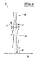
- den vergrößerten Ausschnitt A aus dem Gegenstand der
Fig. 1 .
- Fig. 1
- a vertical section through a device according to the invention and
- Fig. 2
- the enlarged section A from the subject of the
Fig. 1 ,
Die Figuren zeigen eine Vorrichtung zur Herstellung eines Spinnvlieses aus cellulosischen Filamenten. Die Filamente werden dabei aus einer Cellulose-Lösung mittels einer Spinnerette 1 ersponnen. Die Cellulose-Lösung wird dazu der Spinnerette 1 aus einer in
Die Filamente werden vorzugsweise und im Ausführungsbeispiel als Lyocell-Filamente ersponnen. Nach besonders bevorzugter Ausführungsform wird als Cellulose-Lösung eine Lösung von Cellulose in einem Gemisch aus Wasser und einem tertiären Aminoxid eingesetzt. Bei dem tertiären Aminoxid handelt es sich bevorzugt um NMMO. Die Konzentration der Cellulose in der Lösung beträgt zweckmäßigerweise 2 bis 19 Gew.-%.The filaments are preferably and in the embodiment spun as lyocell filaments. According to a particularly preferred embodiment, a solution of cellulose in a mixture of water and a tertiary amine oxide is used as the cellulose solution. The tertiary amine oxide is preferably NMMO. The concentration of the cellulose in the solution is expediently 2 to 19 wt .-%.
In der
Die Kühlkammer 2 ist im Ausführungsbeispiel in zwei Kühlabschnitte 2a und 2b unterteilt. Neben der Kühlkammer 2 ist eine Luftzufuhrkabine 8 angeordnet, die in einen oberen Kabinenabschnitt 8a und in einen unteren Kabinenabschnitt 8b unterteilt ist. Aus den beiden Kabinenabschnitten 8a, 8b ist zweckmäßigerweise jeweils Prozessluft (Kühlluft) mit unterschiedlichem konvektivem Wärmeabführvermögen zuführbar. Vorzugsweise ist aus den beiden Kabinenabschnitten 8a, 8b Prozessluft unterschiedlicher Temperatur zuführbar. Zweckmäßigerweise gelangt aus dem oberen Kabinenabschnitt 8a Prozessluft mit einer Temperatur zwischen 18 °C und 80 °C in die Kühlkammer 2 bzw. in den ersten oberen Kühlabschnitt 2a. Vorzugsweise gelangt aus dem unteren Kabinenabschnitt 8b Prozessluft mit einer Temperatur zwischen 18 °C und 35 °C in die Kühlkammer 2 bzw. in den zweiten unteren Kühlabschnitt 2b. Nach besonders bevorzugter Ausführungsform der Erfindung hat die aus dem oberen Kabinenabschnitt 8a austretende Prozessluft eine höhere Temperatur als die aus dem unteren Kabinenabschnitt 8b austretende Prozessluft. Gemäß einer anderen Ausführungsform kann zur Einstellung besonderer Verhältnisse aber auch die aus dem oberen Kabinenabschnitt 8a austretende Prozessluft eine niedrigere Temperatur haben als die aus dem unteren Kabinenabschnitt 8b austretende Prozessluft. Zweckmäßigerweise ist an die Kabinenabschnitte 8a, 8b jeweils ein Gebläse 9a, 9b zur Zuführung von Prozessluft angeschlossen. Es liegt weiterhin im Rahmen der Erfindung, dass die Mengen bzw. die Volumenströme der den Kühlabschnitten 2a, 2b zugeführten Luft unterschiedlich sind und vorzugsweise regelbar sind. Es liegt fernerhin im Rahmen der Erfindung, dass die Temperatur der jeweils den Kühlabschnitten 2a, 2b zugeführten Prozessluft regelbar ist.The cooling
In der
Vorzugsweise und im Ausführungsbeispiel (siehe insbesondere
Die
Nach einer bevorzugten Ausführungsform der Erfindung ist das Aggregat aus Kühlkammer 2, Zwischenkanal 3, Unterziehkanal 5 und Verlegeeinheit 6, abgesehen von der Luftzuführung in der Kühlkammer 2 und dem Lufteintritt am Umgebungslufteintrittsspalt 15 als geschlossenes System ausgebildet. Das bedeutet, dass zweckmäßigerweise ansonsten keine Luftzufuhr von außen in dieses Aggregat und insbesondere nicht zwischen Kühlkammer 2 und Zwischenkanal 3 sowie nicht zwischen Zwischenkanal 3 und Unterziehkanal 5 stattfindet.According to a preferred embodiment of the invention, the aggregate of cooling
Die aus der Verlegeeinheit 6 austretenden Filamente werden zur Vliesbahn auf dem Ablagesiebband 7 abgelegt. Unter diesem luft- und wasserdurchlässigen Ablagesiebband 7 befindet sich vorzugsweise und im Ausführungsbeispiel eine Absaugvorrichtung 19, die Luft und Waschflüssigkeit von unten durch das Ablagesiebband 7 saugt. Die auf dem Ablagesiebband 7 abgelegte Vliesbahn wird anschließend durch eine Waschstation 16 geführt, in der die Vliesbahn mit einem wässrigen Medium gewaschen wird. Bei diesem wässrigen Medium handelt es sich vorzugsweise um Wasser und/oder um eine wässrige NMMO-Lösung bzw. um ein Gemisch von Wasser und NMMO. Daraufhin wird die Vliesbahn durch eine Entwässerungsstation 17 geführt, in der eine Entwässerung der Vliesbahn stattfindet. Die Entwässerung kann durch Vakuumbehandlung und/oder durch Quetschen in einem Quetschwerk stattfinden. Es liegt im Rahmen der Erfindung, dass die Vliesbahn danach erneut in einer weiteren Waschstation 16 gewaschen und danach in einer weiteren Entwässerungsstation 17 entwässert wird, wobei sich dieser Vorgang (Waschen und Entwässern) vorzugsweise zumindest dreimal wiederholt. Danach wird die Vliesbahn zweckmäßigerweise getrocknet und gemäß einer bevorzugten Ausführungsform aufgewickelt.The emerging from the laying
Claims (13)
- A method for the manufacture of a spunbonded fabric from cellulose filaments, wherein
the filaments are spun from a cellulose solution by means of a spinneret (1), wherein
the cellulose filaments are subsequently introduced into a cooling chamber (2) comprising at least two cooling sections (2a, 2b), wherein the filaments in the two cooling sections (2a, 2b) are in each case impinged upon by differing quantities of process air, i.e. cooling air, at differing temperatures and/or differing air humidities, wherein.
after cooling in the cooling chamber (2) the filaments are aerodynamically stretched, wherein
the filaments are aerodynamically stretched in a stretching unit (4) downstream of the cooling chamber (2) and are deposited on a deposition device, wherein
a laying unit (6) with at least one diffuser (13, 14) is arranged between the stretching unit (4) and a deposition device, and wherein
an aqueous medium for the coagulation of the filaments is introduced via openings in the diffuser wall. - A method for the manufacture of a spunbonded fabric from cellulose filaments, wherein
the filaments are spun from a cellulose solution by means of a spinneret (1), wherein
the cellulose filaments are subsequently introduced into a cooling chamber (2) comprising at least two cooling sections (2a, 2b), wherein the filaments in the two cooling sections (2a, 2b) are in each case impinged upon by differing quantities of process air, i.e. cooling air, at differing temperatures and/or differing air humidities, wherein
after the cooling in the cooling chamber (2) the filaments are aerodynamically stretched in a stretching unit. and are subsequently fed through a laying unit with a first diffuser and a subsequent second diffuser, and are then deposited on a deposition device, wherein
an ambient air entry gap is provided between the first and the second diffusers, and wherein
the filaments are treated via this ambient air entry gap, with the stipulation that a coagulation of the cellulose takes place, and/or wherein
the substances promoting the coagulation are introduced via openings in the diffuser walls. - The method in accordance with Claim 1 or 2, wherein the filaments are spun as lyocell filaments.
- The method in accordance with one of the Claims 1 to 3, wherein a solution of cellulose in a mixture of water and a tertiary amine oxide is deployed as the cellulose solution.
- The method in accordance with one of the Claims 1 to 4, wherein the concentration of the cellulose in the cellulose solution is 0.5 to 25% by weight, preferentially 1 to 22% by weight.
- The method in accordance with one of the Claims 1 to 5, wherein the ratio of the quantity of air supplied to the first cooling section (2a) to the quantity of air supplied to the second cooling section (2b) is 1:10 to 1:1, preferentially 1.5:10 to 6:10, and preferably 1.5:10 to 4.5:10.
- The method in accordance with one of the Claims 1 to 6, wherein the temperature of the cooling air supplied to the first cooling section (2a) is 18 to 80 °C, and the temperature of the cooling air supplied to the second cooling section (2b) is 18 to 35 °C.
- The method in accordance with one of the Claims 1 to 6, wherein before the deposition onto the deposition device the filaments are treated with the stipulation that a coagulation of the cellulose takes place.
- The method in accordance with one of the Claims 1 to 7, wherein after the deposition of the filaments the fabric web formed is treated, i.e. washed, with an aqueous medium, and is subsequently drained.
- A device for the execution of the method in accordance with one of the Claims 1 to 9, - with a spinneret (1), a cooling chamber (2), a stretching unit (4) and a deposition device, wherein filaments can be spun from a cellulose solution with the spinneret (1), wherein
the cooling chamber (2) is subdivided into at least two cooling sections (2a, 2b), in each of which the filaments can be impinged upon by differing quantities of process air, i.e. cooling air, at differing temperatures and/or differing air humidities, wherein
a laying unit (6) with at least one diffuser (13, 14) is arranged between the stretching unit (4) and a deposition device, and wherein
an aqueous medium for the coagulation of the filaments can be introduced via openings in the diffuser wall. - A device for the execution of the method in accordance with one of the Claims 1 to 9, - with a spinneret (1), a cooling chamber (2), a stretching unit (4) and a deposition device, wherein filaments can be spun from a cellulose solution with the spinneret (1), wherein
the cooling chamber (2) is subdivided into at least two cooling sections (2a, 2b), in each of which the filaments can be impinged upon by differing quantities of process air, i.e. cooling air, at differing temperatures and/or differing air humidities, wherein
the deposition unit consists of a first diffuser and a subsequent second diffuser, wherein
an ambient air entry gap is provided between the first and the second diffusers, wherein
the filaments are treated via this ambient air entry gap with the stipulation that a coagulation of the cellulose takes place. - The device in accordance with Claim 10 or 11, wherein the spinneret (1) has a hole density of 0.5 to 9 holes/cm2, preferentially 1 to 8 holes/cm2, and preferably 1.5 to 7.5 holes/cm2.
- The device according to one of the Claims 10 or 11, wherein the connection between the cooling chamber and the stretching unit (4) is designed to be closed externally, i.e. is free of any external air supply.
Priority Applications (13)
| Application Number | Priority Date | Filing Date | Title |
|---|---|---|---|
| EP06026730.9A EP1936017B1 (en) | 2006-12-22 | 2006-12-22 | Method and device for manufacturing a spunbonding fabric made of cellulose filaments |
| DK06026730.9T DK1936017T3 (en) | 2006-12-22 | 2006-12-22 | Method and device for making spunbonded fabric from cellulose filaments |
| ES06026730T ES2434019T3 (en) | 2006-12-22 | 2006-12-22 | Procedure and device for the manufacture of a spunbond fabric from cellulose filaments |
| IL188097A IL188097A (en) | 2006-12-22 | 2007-12-12 | Method and device for the manufacture of a spunbonded fabric of cellulosic filaments |
| CA2615148A CA2615148C (en) | 2006-12-22 | 2007-12-17 | Method and device for the manufacture of a spunbonded fabric of cellulosic filaments |
| ARP070105683A AR064408A1 (en) | 2006-12-22 | 2007-12-18 | PROCEDURE FOR MANUFACTURING NON-WOVEN TEXTILE MATERIAL FROM FILMS OR CELLULOSICAL FIBERS AND DEVICE FOR CARRYING OUT |
| MX2007016424A MX2007016424A (en) | 2006-12-22 | 2007-12-19 | Method and device for manufacturing a spunbonding fabric made of cellulose filaments . |
| KR1020070134233A KR100987743B1 (en) | 2006-12-22 | 2007-12-20 | Method and device for the manufacture of a spunbonded fabric of cellulosic filaments |
| US12/004,446 US20090026647A1 (en) | 2006-12-22 | 2007-12-20 | Making a spunbond fleece from cellulosic filaments |
| JP2007328121A JP5065873B2 (en) | 2006-12-22 | 2007-12-20 | Method and apparatus for producing a spunbonded nonwoven fabric of cellulose filaments |
| RU2007147960/12A RU2399702C2 (en) | 2006-12-22 | 2007-12-21 | Method and device for manufacturing of non-woven material from cellulose fibres produced by die method |
| CN2007103062635A CN101235580B (en) | 2006-12-22 | 2007-12-21 | Method and device for the manufacture of a spunbonded fabric of cellulosic filaments |
| BRPI0704975-7A BRPI0704975A (en) | 2006-12-22 | 2007-12-26 | method and device for the manufacture of a cellulosic filament spinning bonded fabric |
Applications Claiming Priority (1)
| Application Number | Priority Date | Filing Date | Title |
|---|---|---|---|
| EP06026730.9A EP1936017B1 (en) | 2006-12-22 | 2006-12-22 | Method and device for manufacturing a spunbonding fabric made of cellulose filaments |
Publications (2)
| Publication Number | Publication Date |
|---|---|
| EP1936017A1 EP1936017A1 (en) | 2008-06-25 |
| EP1936017B1 true EP1936017B1 (en) | 2013-08-21 |
Family
ID=38512139
Family Applications (1)
| Application Number | Title | Priority Date | Filing Date |
|---|---|---|---|
| EP06026730.9A Active EP1936017B1 (en) | 2006-12-22 | 2006-12-22 | Method and device for manufacturing a spunbonding fabric made of cellulose filaments |
Country Status (13)
| Country | Link |
|---|---|
| US (1) | US20090026647A1 (en) |
| EP (1) | EP1936017B1 (en) |
| JP (1) | JP5065873B2 (en) |
| KR (1) | KR100987743B1 (en) |
| CN (1) | CN101235580B (en) |
| AR (1) | AR064408A1 (en) |
| BR (1) | BRPI0704975A (en) |
| CA (1) | CA2615148C (en) |
| DK (1) | DK1936017T3 (en) |
| ES (1) | ES2434019T3 (en) |
| IL (1) | IL188097A (en) |
| MX (1) | MX2007016424A (en) |
| RU (1) | RU2399702C2 (en) |
Families Citing this family (15)
| Publication number | Priority date | Publication date | Assignee | Title |
|---|---|---|---|---|
| JP2002302862A (en) * | 2001-04-06 | 2002-10-18 | Mitsui Chemicals Inc | Method of producing nonwoven fabric and apparatus therefor |
| EP2179084B1 (en) * | 2007-07-25 | 2011-09-14 | Oerlikon Textile Components GmbH | Apparatus for treating a multifilament thread |
| WO2009031868A2 (en) * | 2007-09-07 | 2009-03-12 | Kolon Industries, Inc. | Lyocell filament fiber and cellulose based tire cord |
| DK2128320T3 (en) * | 2008-05-29 | 2014-01-13 | Reifenhaeuser Gmbh & Co Kg | Method and apparatus for making filter cloth of filaments |
| TWI385286B (en) * | 2009-08-13 | 2013-02-11 | Taiwan Textile Res Inst | Apparatus for manufacturing nonwoven fabric |
| WO2016173828A1 (en) * | 2015-04-25 | 2016-11-03 | Oerlikon Textile Gmbh & Co. Kg | Process and device for the melt spinning and cooling of multifilament threads |
| DE102016119866A1 (en) * | 2016-10-18 | 2018-04-19 | Reifenhäuser GmbH & Co. KG Maschinenfabrik | Method and plant for producing a fleece of fibers |
| AT519489B1 (en) * | 2016-10-21 | 2021-11-15 | Chemiefaser Lenzing Ag | Method and apparatus for producing cellulose-based nonwovens which are formed directly from Lyocell spinning solution |
| EP3382080B1 (en) * | 2017-03-28 | 2019-08-07 | Reifenhäuser GmbH & Co. KG Maschinenfabrik | Method and device for producing a non-woven fabric from fibres |
| SI3382082T1 (en) * | 2017-03-31 | 2019-11-29 | Reifenhaeuser Masch | Device for the manufacture of woven material from continuous filaments |
| JO3481B1 (en) * | 2017-03-31 | 2020-07-05 | Reifenhaeuser Masch | Device for the manufacture of woven material from continuous filaments |
| US11091861B2 (en) * | 2018-01-31 | 2021-08-17 | Fibertex Personal Care A/S | Spunbonded nonwoven with crimped fine fibers |
| EP3575468B1 (en) * | 2018-05-28 | 2020-08-19 | Reifenhäuser GmbH & Co. KG Maschinenfabrik | Device and method for the manufacture of woven material from continuous filaments |
| ES2841727T3 (en) * | 2018-05-28 | 2021-07-09 | Reifenhaeuser Masch | Continuous filament-based spinning veil manufacturing device |
| IT201900023235A1 (en) * | 2019-12-06 | 2021-06-06 | Ramina S R L | PLANT FOR THE PRODUCTION OF NON-WOVEN FABRIC |
Family Cites Families (30)
| Publication number | Priority date | Publication date | Assignee | Title |
|---|---|---|---|---|
| US3959421A (en) * | 1974-04-17 | 1976-05-25 | Kimberly-Clark Corporation | Method for rapid quenching of melt blown fibers |
| US4141913A (en) * | 1978-01-23 | 1979-02-27 | American Carbonyl, Inc. | Method of generating lower alkyl and cycloalkyl isocyanates |
| US4318774A (en) * | 1980-05-01 | 1982-03-09 | Powell Corporation | Composite nonwoven web |
| GB9500387D0 (en) * | 1995-01-10 | 1995-03-01 | Courtaulds Fibres Ltd | Manufacture of extruded articles |
| AT402741B (en) * | 1995-10-13 | 1997-08-25 | Chemiefaser Lenzing Ag | METHOD FOR PRODUCING CELLULOSIC FIBERS |
| DE19620379C2 (en) * | 1996-05-21 | 1998-08-13 | Reifenhaeuser Masch | Plant for the continuous production of a spunbonded nonwoven web |
| US6235392B1 (en) * | 1996-08-23 | 2001-05-22 | Weyerhaeuser Company | Lyocell fibers and process for their preparation |
| GB9625634D0 (en) * | 1996-12-10 | 1997-01-29 | Courtaulds Fibres Holdings Ltd | Method of manufacture of nonwoven fabric |
| US6773648B2 (en) * | 1998-11-03 | 2004-08-10 | Weyerhaeuser Company | Meltblown process with mechanical attenuation |
| US20050048152A1 (en) * | 1999-06-24 | 2005-03-03 | Luder Gerking | Device for spinning materials forming threads |
| DE10023391A1 (en) * | 2000-05-12 | 2001-03-15 | Lurgi Zimmer Ag | Production of cellulosic articles, e.g. fibers, comprises extruding solution to produce fiber, stretching article produced, feeding it without tension to conveyor and removing it from end of conveyor under tension |
| DE10025231A1 (en) * | 2000-05-22 | 2000-11-02 | Lurgi Zimmer Ag | Extrusion of continuous filaments or film from a solution of water with cellulose and a tertiary amine oxide has a structured air drawing action in the air gap after the extrusion channel to increase the material strength |
| US7244497B2 (en) * | 2001-09-21 | 2007-07-17 | Outlast Technologies, Inc. | Cellulosic fibers having enhanced reversible thermal properties and methods of forming thereof |
| GB2368342A (en) * | 2000-10-12 | 2002-05-01 | Tencel Ltd | Lyocell fibre and its production |
| US6607624B2 (en) * | 2000-11-20 | 2003-08-19 | 3M Innovative Properties Company | Fiber-forming process |
| DE10065859B4 (en) * | 2000-12-22 | 2006-08-24 | Gerking, Lüder, Dr.-Ing. | Method and apparatus for producing substantially endless fine threads |
| JP4187532B2 (en) * | 2001-03-26 | 2008-11-26 | マイクレックス コーポレーション | Wiping using non-woven fabric |
| JP2002302862A (en) * | 2001-04-06 | 2002-10-18 | Mitsui Chemicals Inc | Method of producing nonwoven fabric and apparatus therefor |
| ATE381630T1 (en) * | 2002-02-28 | 2008-01-15 | Reifenhaeuser Gmbh & Co Kg | SYSTEM FOR THE CONTINUOUS PRODUCTION OF A SPUNNOVED WEB |
| EP1396567B2 (en) * | 2002-08-09 | 2011-04-20 | Reifenhäuser GmbH & Co. KG Maschinenfabrik | Method of producing a nonwoven web of bicomponent filaments |
| US20040110442A1 (en) * | 2002-08-30 | 2004-06-10 | Hannong Rhim | Stretchable nonwoven materials with controlled retraction force and methods of making same |
| US20090233075A1 (en) * | 2002-10-01 | 2009-09-17 | Freudenberg Nonwovens Limited Partnership | Flame Blocking Liner Materials |
| DE10314878A1 (en) * | 2003-04-01 | 2004-10-28 | Zimmer Ag | Method and device for producing post-stretched cellulose filaments |
| US20050056956A1 (en) * | 2003-09-16 | 2005-03-17 | Biax Fiberfilm Corporation | Process for forming micro-fiber cellulosic nonwoven webs from a cellulose solution by melt blown technology and the products made thereby |
| US7459015B2 (en) * | 2004-04-16 | 2008-12-02 | Birla Research Institute For Applied Sciences | Process for the preparation of a cellulose solution for spinning of fibres, filaments or films therefrom |
| DE102004024029A1 (en) * | 2004-05-13 | 2005-12-08 | Zimmer Ag | Lyocell method and apparatus with metal ion content control |
| ES2432014T3 (en) * | 2004-07-29 | 2013-11-29 | Suominen Corporation | Method for manufacturing particularly soft and three-dimensional nonwoven fabrics and nonwoven fabrics thus obtained |
| US20080058748A1 (en) * | 2006-08-29 | 2008-03-06 | Seifert Kathy P | Disposable absorbent article having a graphic adapted to facilitate discretionary use of said article |
| US8277711B2 (en) * | 2007-03-29 | 2012-10-02 | E I Du Pont De Nemours And Company | Production of nanofibers by melt spinning |
| TWI337634B (en) * | 2007-12-27 | 2011-02-21 | Taiwan Textile Res Inst | Apparatus and method for manufacturing nonwoven fabric |
-
2006
- 2006-12-22 DK DK06026730.9T patent/DK1936017T3/en active
- 2006-12-22 ES ES06026730T patent/ES2434019T3/en active Active
- 2006-12-22 EP EP06026730.9A patent/EP1936017B1/en active Active
-
2007
- 2007-12-12 IL IL188097A patent/IL188097A/en not_active IP Right Cessation
- 2007-12-17 CA CA2615148A patent/CA2615148C/en not_active Expired - Fee Related
- 2007-12-18 AR ARP070105683A patent/AR064408A1/en active IP Right Grant
- 2007-12-19 MX MX2007016424A patent/MX2007016424A/en active IP Right Grant
- 2007-12-20 US US12/004,446 patent/US20090026647A1/en not_active Abandoned
- 2007-12-20 JP JP2007328121A patent/JP5065873B2/en active Active
- 2007-12-20 KR KR1020070134233A patent/KR100987743B1/en not_active IP Right Cessation
- 2007-12-21 CN CN2007103062635A patent/CN101235580B/en not_active Expired - Fee Related
- 2007-12-21 RU RU2007147960/12A patent/RU2399702C2/en not_active IP Right Cessation
- 2007-12-26 BR BRPI0704975-7A patent/BRPI0704975A/en not_active IP Right Cessation
Also Published As
| Publication number | Publication date |
|---|---|
| US20090026647A1 (en) | 2009-01-29 |
| CN101235580A (en) | 2008-08-06 |
| RU2007147960A (en) | 2009-06-27 |
| AR064408A1 (en) | 2009-04-01 |
| EP1936017A1 (en) | 2008-06-25 |
| DK1936017T3 (en) | 2013-11-04 |
| JP5065873B2 (en) | 2012-11-07 |
| RU2399702C2 (en) | 2010-09-20 |
| ES2434019T3 (en) | 2013-12-13 |
| KR20080059055A (en) | 2008-06-26 |
| JP2008163540A (en) | 2008-07-17 |
| IL188097A (en) | 2011-05-31 |
| KR100987743B1 (en) | 2010-10-18 |
| BRPI0704975A (en) | 2008-08-12 |
| IL188097A0 (en) | 2008-12-29 |
| MX2007016424A (en) | 2008-10-28 |
| CA2615148A1 (en) | 2008-06-22 |
| CA2615148C (en) | 2011-06-28 |
| CN101235580B (en) | 2013-03-27 |
Similar Documents
| Publication | Publication Date | Title |
|---|---|---|
| EP1936017B1 (en) | Method and device for manufacturing a spunbonding fabric made of cellulose filaments | |
| EP0494852B1 (en) | Process for the production of cellulosic articles | |
| DE10065859B4 (en) | Method and apparatus for producing substantially endless fine threads | |
| EP1967628B2 (en) | Method and device for producing spinning fleece | |
| AT519489A1 (en) | A method and apparatus for producing cellulosic webs formed directly from lyocell spinning solution | |
| EP1630265B1 (en) | Apparatus for the continuous production of a spunbonded web | |
| DE60036994T2 (en) | Nonwoven fabric of polypropylene fiber and process for its production | |
| DE4219658C2 (en) | Process for the production of cellulose fiber filaments and foils by the dry-wet extrusion process | |
| EP2009163B1 (en) | Method for manufacturing non woven material | |
| EP1280946B1 (en) | Method and device for conveying continuous shaped bodies without tensile stress | |
| WO2005080661A1 (en) | Method for the production of non-wovens, non-wovens, and use thereof | |
| WO1996017118A1 (en) | Method of producing shaped cellulose bodies, and yarn made of cellulose filaments | |
| EP1716278B1 (en) | Method for producing non-wovens, a corresponding non-woven and the production thereof | |
| WO2007023003A1 (en) | Multiple spinning nozzle arrangement and method for suctioning and blowing | |
| WO2017129318A1 (en) | Device for producing spunbonded webs | |
| EP1268888A1 (en) | Method and device for the production of cellulose fibres and cellulose filament yarns | |
| DE102016217048B4 (en) | Process for the production of cellulose filaments, spunbonded nonwovens produced therewith and their use | |
| EP4077789A1 (en) | Method for producing a spunbond nonwoven | |
| EP4110980A1 (en) | Method and device for producing spunbonded fabric | |
| WO2021122377A1 (en) | Method for producing a spunbond nonwoven | |
| DE2326837A1 (en) | PROCESS FOR THE PRODUCTION OF FIBER-SHAPED STRETCHED FORMATIONS FROM POLYMER SUBSTANCES | |
| DE102004024065A1 (en) | Process for producing continuous moldings and spinning head | |
| WO2021122378A1 (en) | Method for producing spunbonded fabric | |
| WO2013011133A1 (en) | Ultrathin carbon fibers |
Legal Events
| Date | Code | Title | Description |
|---|---|---|---|
| PUAI | Public reference made under article 153(3) epc to a published international application that has entered the european phase |
Free format text: ORIGINAL CODE: 0009012 |
|
| AK | Designated contracting states |
Kind code of ref document: A1 Designated state(s): AT BE BG CH CY CZ DE DK EE ES FI FR GB GR HU IE IS IT LI LT LU LV MC NL PL PT RO SE SI SK TR |
|
| AX | Request for extension of the european patent |
Extension state: AL BA HR MK RS |
|
| 17P | Request for examination filed |
Effective date: 20080718 |
|
| AKX | Designation fees paid |
Designated state(s): AT BE BG CH CY CZ DE DK EE ES FI FR GB GR HU IE IS IT LI LT LU LV MC NL PL PT RO SE SI SK TR |
|
| 17Q | First examination report despatched |
Effective date: 20100615 |
|
| REG | Reference to a national code |
Ref country code: DE Ref legal event code: R079 Ref document number: 502006013132 Country of ref document: DE Free format text: PREVIOUS MAIN CLASS: D04H0003160000 Ipc: D01F0002000000 |
|
| RIC1 | Information provided on ipc code assigned before grant |
Ipc: D01D 5/098 20060101ALI20121214BHEP Ipc: D04H 3/16 20060101ALI20121214BHEP Ipc: D04H 3/015 20120101ALI20121214BHEP Ipc: D01F 2/00 20060101AFI20121214BHEP |
|
| GRAP | Despatch of communication of intention to grant a patent |
Free format text: ORIGINAL CODE: EPIDOSNIGR1 |
|
| GRAS | Grant fee paid |
Free format text: ORIGINAL CODE: EPIDOSNIGR3 |
|
| GRAA | (expected) grant |
Free format text: ORIGINAL CODE: 0009210 |
|
| AK | Designated contracting states |
Kind code of ref document: B1 Designated state(s): AT BE BG CH CY CZ DE DK EE ES FI FR GB GR HU IE IS IT LI LT LU LV MC NL PL PT RO SE SI SK TR |
|
| REG | Reference to a national code |
Ref country code: GB Ref legal event code: FG4D Free format text: NOT ENGLISH |
|
| REG | Reference to a national code |
Ref country code: CH Ref legal event code: EP |
|
| REG | Reference to a national code |
Ref country code: AT Ref legal event code: REF Ref document number: 628176 Country of ref document: AT Kind code of ref document: T Effective date: 20130915 |
|
| REG | Reference to a national code |
Ref country code: IE Ref legal event code: FG4D Free format text: LANGUAGE OF EP DOCUMENT: GERMAN |
|
| REG | Reference to a national code |
Ref country code: DE Ref legal event code: R096 Ref document number: 502006013132 Country of ref document: DE Effective date: 20131017 |
|
| REG | Reference to a national code |
Ref country code: DK Ref legal event code: T3 Effective date: 20131028 Ref country code: DK Ref legal event code: T3 |
|
| REG | Reference to a national code |
Ref country code: SE Ref legal event code: TRGR |
|
| REG | Reference to a national code |
Ref country code: ES Ref legal event code: FG2A Ref document number: 2434019 Country of ref document: ES Kind code of ref document: T3 Effective date: 20131213 |
|
| REG | Reference to a national code |
Ref country code: NL Ref legal event code: T3 |
|
| REG | Reference to a national code |
Ref country code: LT Ref legal event code: MG4D |
|
| PG25 | Lapsed in a contracting state [announced via postgrant information from national office to epo] |
Ref country code: IS Free format text: LAPSE BECAUSE OF FAILURE TO SUBMIT A TRANSLATION OF THE DESCRIPTION OR TO PAY THE FEE WITHIN THE PRESCRIBED TIME-LIMIT Effective date: 20131221 Ref country code: PT Free format text: LAPSE BECAUSE OF FAILURE TO SUBMIT A TRANSLATION OF THE DESCRIPTION OR TO PAY THE FEE WITHIN THE PRESCRIBED TIME-LIMIT Effective date: 20131223 Ref country code: LT Free format text: LAPSE BECAUSE OF FAILURE TO SUBMIT A TRANSLATION OF THE DESCRIPTION OR TO PAY THE FEE WITHIN THE PRESCRIBED TIME-LIMIT Effective date: 20130821 Ref country code: CY Free format text: LAPSE BECAUSE OF FAILURE TO SUBMIT A TRANSLATION OF THE DESCRIPTION OR TO PAY THE FEE WITHIN THE PRESCRIBED TIME-LIMIT Effective date: 20130724 |
|
| PG25 | Lapsed in a contracting state [announced via postgrant information from national office to epo] |
Ref country code: SI Free format text: LAPSE BECAUSE OF FAILURE TO SUBMIT A TRANSLATION OF THE DESCRIPTION OR TO PAY THE FEE WITHIN THE PRESCRIBED TIME-LIMIT Effective date: 20130821 Ref country code: PL Free format text: LAPSE BECAUSE OF FAILURE TO SUBMIT A TRANSLATION OF THE DESCRIPTION OR TO PAY THE FEE WITHIN THE PRESCRIBED TIME-LIMIT Effective date: 20130821 Ref country code: FI Free format text: LAPSE BECAUSE OF FAILURE TO SUBMIT A TRANSLATION OF THE DESCRIPTION OR TO PAY THE FEE WITHIN THE PRESCRIBED TIME-LIMIT Effective date: 20130821 Ref country code: GR Free format text: LAPSE BECAUSE OF FAILURE TO SUBMIT A TRANSLATION OF THE DESCRIPTION OR TO PAY THE FEE WITHIN THE PRESCRIBED TIME-LIMIT Effective date: 20131122 Ref country code: LV Free format text: LAPSE BECAUSE OF FAILURE TO SUBMIT A TRANSLATION OF THE DESCRIPTION OR TO PAY THE FEE WITHIN THE PRESCRIBED TIME-LIMIT Effective date: 20130821 |
|
| PG25 | Lapsed in a contracting state [announced via postgrant information from national office to epo] |
Ref country code: CY Free format text: LAPSE BECAUSE OF FAILURE TO SUBMIT A TRANSLATION OF THE DESCRIPTION OR TO PAY THE FEE WITHIN THE PRESCRIBED TIME-LIMIT Effective date: 20130821 |
|
| PG25 | Lapsed in a contracting state [announced via postgrant information from national office to epo] |
Ref country code: RO Free format text: LAPSE BECAUSE OF FAILURE TO SUBMIT A TRANSLATION OF THE DESCRIPTION OR TO PAY THE FEE WITHIN THE PRESCRIBED TIME-LIMIT Effective date: 20130821 Ref country code: SK Free format text: LAPSE BECAUSE OF FAILURE TO SUBMIT A TRANSLATION OF THE DESCRIPTION OR TO PAY THE FEE WITHIN THE PRESCRIBED TIME-LIMIT Effective date: 20130821 Ref country code: EE Free format text: LAPSE BECAUSE OF FAILURE TO SUBMIT A TRANSLATION OF THE DESCRIPTION OR TO PAY THE FEE WITHIN THE PRESCRIBED TIME-LIMIT Effective date: 20130821 |
|
| PLBE | No opposition filed within time limit |
Free format text: ORIGINAL CODE: 0009261 |
|
| STAA | Information on the status of an ep patent application or granted ep patent |
Free format text: STATUS: NO OPPOSITION FILED WITHIN TIME LIMIT |
|
| BERE | Be: lapsed |
Owner name: REIFENHAUSER G.M.B.H. & CO. KG MASCHINENFABRIK Effective date: 20131231 |
|
| 26N | No opposition filed |
Effective date: 20140522 |
|
| REG | Reference to a national code |
Ref country code: CH Ref legal event code: PL |
|
| PG25 | Lapsed in a contracting state [announced via postgrant information from national office to epo] |
Ref country code: LU Free format text: LAPSE BECAUSE OF FAILURE TO SUBMIT A TRANSLATION OF THE DESCRIPTION OR TO PAY THE FEE WITHIN THE PRESCRIBED TIME-LIMIT Effective date: 20131222 Ref country code: MC Free format text: LAPSE BECAUSE OF FAILURE TO SUBMIT A TRANSLATION OF THE DESCRIPTION OR TO PAY THE FEE WITHIN THE PRESCRIBED TIME-LIMIT Effective date: 20130821 |
|
| REG | Reference to a national code |
Ref country code: DE Ref legal event code: R097 Ref document number: 502006013132 Country of ref document: DE Effective date: 20140522 |
|
| REG | Reference to a national code |
Ref country code: IE Ref legal event code: MM4A |
|
| PG25 | Lapsed in a contracting state [announced via postgrant information from national office to epo] |
Ref country code: IE Free format text: LAPSE BECAUSE OF NON-PAYMENT OF DUE FEES Effective date: 20131222 Ref country code: CH Free format text: LAPSE BECAUSE OF NON-PAYMENT OF DUE FEES Effective date: 20131231 Ref country code: BE Free format text: LAPSE BECAUSE OF NON-PAYMENT OF DUE FEES Effective date: 20131231 Ref country code: LI Free format text: LAPSE BECAUSE OF NON-PAYMENT OF DUE FEES Effective date: 20131231 |
|
| REG | Reference to a national code |
Ref country code: AT Ref legal event code: MM01 Ref document number: 628176 Country of ref document: AT Kind code of ref document: T Effective date: 20131222 |
|
| PG25 | Lapsed in a contracting state [announced via postgrant information from national office to epo] |
Ref country code: AT Free format text: LAPSE BECAUSE OF NON-PAYMENT OF DUE FEES Effective date: 20131222 |
|
| PG25 | Lapsed in a contracting state [announced via postgrant information from national office to epo] |
Ref country code: BG Free format text: LAPSE BECAUSE OF FAILURE TO SUBMIT A TRANSLATION OF THE DESCRIPTION OR TO PAY THE FEE WITHIN THE PRESCRIBED TIME-LIMIT Effective date: 20130821 Ref country code: HU Free format text: LAPSE BECAUSE OF FAILURE TO SUBMIT A TRANSLATION OF THE DESCRIPTION OR TO PAY THE FEE WITHIN THE PRESCRIBED TIME-LIMIT; INVALID AB INITIO Effective date: 20061222 |
|
| REG | Reference to a national code |
Ref country code: FR Ref legal event code: PLFP Year of fee payment: 10 |
|
| REG | Reference to a national code |
Ref country code: FR Ref legal event code: PLFP Year of fee payment: 11 |
|
| REG | Reference to a national code |
Ref country code: FR Ref legal event code: PLFP Year of fee payment: 12 |
|
| PGFP | Annual fee paid to national office [announced via postgrant information from national office to epo] |
Ref country code: SE Payment date: 20211218 Year of fee payment: 16 Ref country code: CZ Payment date: 20211126 Year of fee payment: 16 Ref country code: DK Payment date: 20211217 Year of fee payment: 16 Ref country code: FR Payment date: 20211217 Year of fee payment: 16 Ref country code: GB Payment date: 20211217 Year of fee payment: 16 |
|
| PGFP | Annual fee paid to national office [announced via postgrant information from national office to epo] |
Ref country code: NL Payment date: 20211217 Year of fee payment: 16 |
|
| PGFP | Annual fee paid to national office [announced via postgrant information from national office to epo] |
Ref country code: TR Payment date: 20211216 Year of fee payment: 16 Ref country code: IT Payment date: 20211231 Year of fee payment: 16 Ref country code: ES Payment date: 20220103 Year of fee payment: 16 |
|
| PGFP | Annual fee paid to national office [announced via postgrant information from national office to epo] |
Ref country code: DE Payment date: 20221229 Year of fee payment: 17 |
|
| REG | Reference to a national code |
Ref country code: DK Ref legal event code: EBP Effective date: 20221231 |
|
| PG25 | Lapsed in a contracting state [announced via postgrant information from national office to epo] |
Ref country code: CZ Free format text: LAPSE BECAUSE OF NON-PAYMENT OF DUE FEES Effective date: 20221222 |
|
| REG | Reference to a national code |
Ref country code: SE Ref legal event code: EUG |
|
| REG | Reference to a national code |
Ref country code: NL Ref legal event code: MM Effective date: 20230101 |
|
| GBPC | Gb: european patent ceased through non-payment of renewal fee |
Effective date: 20221222 |
|
| PG25 | Lapsed in a contracting state [announced via postgrant information from national office to epo] |
Ref country code: NL Free format text: LAPSE BECAUSE OF NON-PAYMENT OF DUE FEES Effective date: 20230101 |
|
| PG25 | Lapsed in a contracting state [announced via postgrant information from national office to epo] |
Ref country code: SE Free format text: LAPSE BECAUSE OF NON-PAYMENT OF DUE FEES Effective date: 20221223 Ref country code: GB Free format text: LAPSE BECAUSE OF NON-PAYMENT OF DUE FEES Effective date: 20221222 |
|
| PG25 | Lapsed in a contracting state [announced via postgrant information from national office to epo] |
Ref country code: FR Free format text: LAPSE BECAUSE OF NON-PAYMENT OF DUE FEES Effective date: 20221231 |
|
| PG25 | Lapsed in a contracting state [announced via postgrant information from national office to epo] |
Ref country code: IT Free format text: LAPSE BECAUSE OF NON-PAYMENT OF DUE FEES Effective date: 20221222 Ref country code: DK Free format text: LAPSE BECAUSE OF NON-PAYMENT OF DUE FEES Effective date: 20221231 |
|
| REG | Reference to a national code |
Ref country code: ES Ref legal event code: FD2A Effective date: 20240131 |