EP1935606A1 - Grounded manifold and method for making the same - Google Patents
Grounded manifold and method for making the same Download PDFInfo
- Publication number
- EP1935606A1 EP1935606A1 EP07122111A EP07122111A EP1935606A1 EP 1935606 A1 EP1935606 A1 EP 1935606A1 EP 07122111 A EP07122111 A EP 07122111A EP 07122111 A EP07122111 A EP 07122111A EP 1935606 A1 EP1935606 A1 EP 1935606A1
- Authority
- EP
- European Patent Office
- Prior art keywords
- ports
- electrically conductive
- inserts
- spring
- port
- Prior art date
- Legal status (The legal status is an assumption and is not a legal conclusion. Google has not performed a legal analysis and makes no representation as to the accuracy of the status listed.)
- Granted
Links
- 238000000034 method Methods 0.000 title claims description 22
- 230000005540 biological transmission Effects 0.000 claims abstract description 21
- 238000000465 moulding Methods 0.000 claims description 12
- 239000002184 metal Substances 0.000 claims description 9
- 229910052751 metal Inorganic materials 0.000 claims description 9
- 238000010438 heat treatment Methods 0.000 claims description 6
- 239000000463 material Substances 0.000 abstract description 9
- 230000008901 benefit Effects 0.000 description 6
- 238000004519 manufacturing process Methods 0.000 description 6
- 229920003023 plastic Polymers 0.000 description 5
- 239000004033 plastic Substances 0.000 description 5
- 230000006698 induction Effects 0.000 description 4
- 238000003780 insertion Methods 0.000 description 3
- 230000037431 insertion Effects 0.000 description 3
- 239000012811 non-conductive material Substances 0.000 description 3
- 150000002739 metals Chemical class 0.000 description 2
- 229910052755 nonmetal Inorganic materials 0.000 description 2
- 150000002843 nonmetals Chemical class 0.000 description 2
- 229920002994 synthetic fiber Polymers 0.000 description 2
- 229910001369 Brass Inorganic materials 0.000 description 1
- 239000010951 brass Substances 0.000 description 1
- 238000005266 casting Methods 0.000 description 1
- 239000004020 conductor Substances 0.000 description 1
- 238000010276 construction Methods 0.000 description 1
- 238000005260 corrosion Methods 0.000 description 1
- 230000007797 corrosion Effects 0.000 description 1
- 239000012530 fluid Substances 0.000 description 1
- 238000003754 machining Methods 0.000 description 1
- 238000012986 modification Methods 0.000 description 1
- 230000004048 modification Effects 0.000 description 1
- 238000005498 polishing Methods 0.000 description 1
- 238000003825 pressing Methods 0.000 description 1
- 230000000717 retained effect Effects 0.000 description 1
- 238000004381 surface treatment Methods 0.000 description 1
Images
Classifications
-
- F—MECHANICAL ENGINEERING; LIGHTING; HEATING; WEAPONS; BLASTING
- F16—ENGINEERING ELEMENTS AND UNITS; GENERAL MEASURES FOR PRODUCING AND MAINTAINING EFFECTIVE FUNCTIONING OF MACHINES OR INSTALLATIONS; THERMAL INSULATION IN GENERAL
- F16H—GEARING
- F16H61/00—Control functions within control units of change-speed- or reversing-gearings for conveying rotary motion ; Control of exclusively fluid gearing, friction gearing, gearings with endless flexible members or other particular types of gearing
- F16H61/0003—Arrangement or mounting of elements of the control apparatus, e.g. valve assemblies or snapfittings of valves; Arrangements of the control unit on or in the transmission gearbox
- F16H61/0009—Hydraulic control units for transmission control, e.g. assembly of valve plates or valve units
-
- Y—GENERAL TAGGING OF NEW TECHNOLOGICAL DEVELOPMENTS; GENERAL TAGGING OF CROSS-SECTIONAL TECHNOLOGIES SPANNING OVER SEVERAL SECTIONS OF THE IPC; TECHNICAL SUBJECTS COVERED BY FORMER USPC CROSS-REFERENCE ART COLLECTIONS [XRACs] AND DIGESTS
- Y10—TECHNICAL SUBJECTS COVERED BY FORMER USPC
- Y10T—TECHNICAL SUBJECTS COVERED BY FORMER US CLASSIFICATION
- Y10T29/00—Metal working
- Y10T29/49—Method of mechanical manufacture
- Y10T29/49002—Electrical device making
-
- Y—GENERAL TAGGING OF NEW TECHNOLOGICAL DEVELOPMENTS; GENERAL TAGGING OF CROSS-SECTIONAL TECHNOLOGIES SPANNING OVER SEVERAL SECTIONS OF THE IPC; TECHNICAL SUBJECTS COVERED BY FORMER USPC CROSS-REFERENCE ART COLLECTIONS [XRACs] AND DIGESTS
- Y10—TECHNICAL SUBJECTS COVERED BY FORMER USPC
- Y10T—TECHNICAL SUBJECTS COVERED BY FORMER US CLASSIFICATION
- Y10T428/00—Stock material or miscellaneous articles
- Y10T428/24—Structurally defined web or sheet [e.g., overall dimension, etc.]
- Y10T428/24273—Structurally defined web or sheet [e.g., overall dimension, etc.] including aperture
Definitions
- the present invention relates generally to molded articles of non-conductive material and, more specifically, to structures within such molded articles for establishing ground connections between opposite sides of the article.
- Synthetic materials such as plastics can provide improved characteristics over metals for some components.
- materials which are reactively inert to fluids used in the automobile can provide improved corrosion resistance and longer life.
- some plastic components have inherent sound deadening qualities when compared to metallic components and strength or impact resistance qualities that are advantageous.
- Alternative materials to metals are considered also for use in complex parts that can be expensive to manufacture of metal by machining, casting and finishing/polishing or the like. Molding techniques to create the parts from nonmetals can be performed quickly and efficiently when compared to previously used processes for metallic parts. For example, a transmission manifold may require a plurality of ports on opposite sides thereof, which can be complex and costly to manufacture completely from metal, and manufacturing a body of plastic with metal inserts can provide advantages. Metal components also can be heavier than similar parts from nonmetals. Accordingly, alternative materials may reduce weight and increase operating efficiency for the automobile, in addition to reducing costs and expenses for supplying the part.
- Some components including for example a transmission manifold, must provide a ground connection therethrough in the completed assembly. If the manifold or other component is manufactured of non-conductive material, establishing a ground connection from one side thereof to an opposite side thereof can present difficulties. It is known that some of the ports on opposite sides of a transmission manifold, for example, can provide a continuous passage through the manifold between opposite sides thereof. A metallic insert used in the port can be used to establish a ground connection from one side thereof to the other side thereof. However, the required shapes for such inserts are complex and may have opposite ends in axial non-alignment. Accordingly, a one-piece metallic insert can be complex, difficult to manufacture and install and expensive.
- the present invention provides an apparatus and method of making the apparatus with a continuous passage from one side of a non-conductive body, such as a transmission manifold, to an opposite side of the non-conductive body, with conductive inserts secured and extending into the passage from opposite sides of the body.
- a space in the passageway between the inner ends of the inserts contains a compressed conductive spring establishing electrical contact with each insert on opposite ends of the spring.
- the present invention provides an electrically conductive assembly with a low conductivity body having first and second faces with first and second ports in the first and second faces.
- a first electrically conductive element extends into the body from the first port;
- a second electrically conductive element extends into the body from the second port, and
- an electrically conductive spring within the body is between and in electrically conductive contact with the first and second electrically conductive elements at opposite ends of the spring.
- the present invention provides a transmission manifold with a low electrical conductivity body having a first face and a second face on opposite first and second sides of the body.
- a first port is defined in the first face; a second port is defined in the second face, and a continuous passage is provided through the body from the first port to the second port.
- a first electrically conductive insert extends into the passage from the first port; a second electrically conductive insert extends into the passage from the second port, and an electrically conductive spring is disposed between and in electrical contact with the first and second inserts within the passage.
- the present invention provides a method for making a transmission manifold with steps of molding a transmission manifold body with first and second ports on opposite faces thereof, including forming one first port and one second port with a continuous passage therebetween; securing a first electrically conductive insert in one of the first and second ports; positioning an electrically conductive spring in electrically conductive contact with the first insert; securing a second electrically conductive insert in the other of the first and second ports; compressing the spring between the first and second inserts; and establishing continuous simultaneous electrical contact between the spring and each the first insert and the second insert within the passage.
- An advantage of the present invention in one form thereof, is providing a synthetic body establishing ground connection from one side to the other side.
- Another advantage of the present invention in one form thereof, is providing an efficient and cost effective structure for establishing electrical contact between opposite sides of a substantially non-conductive body.
- Still another advantage of a form of the present invention is providing a transmission manifold of synthetic material with electrically conductive contact between one side thereof and an opposite side thereof.
- numeral 10 designates an automobile transmission manifold in accordance with the present invention. It should be understood that the particular configuration of a transmission manifold shown in the drawings is merely exemplary in nature, and the present invention can be used for transmission manifolds having other shapes and configurations. Further, while a transmission manifold is one advantageous use for the present invention, it is contemplated that other structures also can benefit from the use and application of the present invention.
- Manifold 10 is a body of material of low electrical conductivity, such as plastic, and has a first face 12 and a second face 14 on opposite sides thereof. At least one first hole or port 16 is provided as an opening in first face 12. A plurality of first ports 16 is shown in Fig. 1 . At least one second hole or port 18 is provided as an opening in second face 14. A plurality of second ports 18 is shown in Fig. 2 . It should be understood that more or fewer first ports 16 and second ports 18 can be used for a specific manifold configuration.
- First inserts 20 are disposed in first ports 16, and second inserts 22 are provided in second ports 18.
- Inserts 20 and 22 can be of different shapes, configurations and sizes as suitable for the port in which each is installed. Knurling or other surface treatments can be provided on outer surfaces of inserts 20 or 22 to enhance fixation within ports 16 and 18.
- Inserts 20, 22 are electrically conductive material, such as brass or other metal, whereas manifold 10 can be otherwise formed of substantially non-conductive material, such as plastic.
- first port 16 and one second port 18 are disposed generally across from one another, and a continuous passageway 24 is established from first port 16 in first face 12 to second port 18 in second face 14.
- first port 16 and second port 18 defining the continuous passage are in axial non-alignment.
- An electrically conductive spring 26 is provided in passage 24, between first insert 20 and second insert 22.
- Spring 26 in the exemplary embodiment is a coil spring with a relaxed length longer than the free space in passage 24 between the inner ends of inserts 20 and 22. In the completed assembly, spring 24 is compressed between insert 20 and insert 22 to provide continuous electrical contact with each insert 20 and insert 22 on opposite ends of spring 26.
- ports 16 and 18 are axially offset. Accordingly, spring 26 is retained between opposed inserts 20 and 22 in axial alignment with one insert 22 but not with the other insert 20.
- a manifold of the present invention can be made by a variety of manufacturing techniques and processes.
- manifold 10 is made by molding, during which the various first ports 16 and second ports 18 are formed.
- First inserts 20 are secured in first ports 16 during the molding process. Accordingly, first inserts 20 are secured in a fixture in the mold cavity, with the material for manifold 10 being molded thereabout.
- Such techniques are often referred to as overmolding. As the material for manifold 10 hardens or cures, intimate contact is established for securing first inserts 20 in the first ports 16 that are formed there around.
- second ports 18 also are formed.
- Second inserts 22 can be secured by post mold inserting in second ports 18 after manifold 10 is removed from the mold in which molding occurs.
- a heated inserting process using, for example, induction heating can be used.
- the insert 22 is heated by induction heating, and then forced into second port 18. It should be understood that heating processes other than induction heating can be used to heat an insert for insertion.
- the heated mass of second insert 22 softens the material of manifold 10 lining passage 24, allowing insertion and subsequent intimate contact between the manifold and the insert.
- first inserts 20 and second inserts 22 can be secured as described. However, it should be understood that a variety of techniques can be used. For example, some or all of the first inserts 20 can be secured in manifold 10 by post mold insertion, using induction inserting other heated inserting process after the manifold is formed in a molding operation. For some uses of the present invention, other post mold inserting processes can be used, and may include pressing or inserting without heating.
- spring 26 is inserted into at least one set of a first ports defining a continuous passage 24 between a first port 16 and a second port 18. For example, after the first insert 20 is secured relative to first port 16, which may be by overmolding, spring 26 is inserted into second port 18. As second insert 22 is inserted into second port 18, spring 26 is encountered and compressed between and against the first and second inserts 20, 22. As illustrated in Fig. 3 , spring 26 thereby establishes continuous electrical contact between first insert 20 and second insert 22.
Landscapes
- Engineering & Computer Science (AREA)
- General Engineering & Computer Science (AREA)
- Mechanical Engineering (AREA)
- Moulds For Moulding Plastics Or The Like (AREA)
- Control Of Transmission Device (AREA)
Abstract
Description
- The present invention relates generally to molded articles of non-conductive material and, more specifically, to structures within such molded articles for establishing ground connections between opposite sides of the article.
- In the automotive industry, alternative materials to metal are considered for many components in automobiles. Synthetic materials such as plastics can provide improved characteristics over metals for some components. For example, materials which are reactively inert to fluids used in the automobile can provide improved corrosion resistance and longer life. Further, some plastic components have inherent sound deadening qualities when compared to metallic components and strength or impact resistance qualities that are advantageous.
- Alternative materials to metals are considered also for use in complex parts that can be expensive to manufacture of metal by machining, casting and finishing/polishing or the like. Molding techniques to create the parts from nonmetals can be performed quickly and efficiently when compared to previously used processes for metallic parts. For example, a transmission manifold may require a plurality of ports on opposite sides thereof, which can be complex and costly to manufacture completely from metal, and manufacturing a body of plastic with metal inserts can provide advantages. Metal components also can be heavier than similar parts from nonmetals. Accordingly, alternative materials may reduce weight and increase operating efficiency for the automobile, in addition to reducing costs and expenses for supplying the part.
- Some components, including for example a transmission manifold, must provide a ground connection therethrough in the completed assembly. If the manifold or other component is manufactured of non-conductive material, establishing a ground connection from one side thereof to an opposite side thereof can present difficulties. It is known that some of the ports on opposite sides of a transmission manifold, for example, can provide a continuous passage through the manifold between opposite sides thereof. A metallic insert used in the port can be used to establish a ground connection from one side thereof to the other side thereof. However, the required shapes for such inserts are complex and may have opposite ends in axial non-alignment. Accordingly, a one-piece metallic insert can be complex, difficult to manufacture and install and expensive.
- The present invention provides an apparatus and method of making the apparatus with a continuous passage from one side of a non-conductive body, such as a transmission manifold, to an opposite side of the non-conductive body, with conductive inserts secured and extending into the passage from opposite sides of the body. A space in the passageway between the inner ends of the inserts contains a compressed conductive spring establishing electrical contact with each insert on opposite ends of the spring.
- In one aspect thereof, the present invention provides an electrically conductive assembly with a low conductivity body having first and second faces with first and second ports in the first and second faces. A first electrically conductive element extends into the body from the first port; a second electrically conductive element extends into the body from the second port, and an electrically conductive spring within the body is between and in electrically conductive contact with the first and second electrically conductive elements at opposite ends of the spring.
- In another aspect thereof, the present invention provides a transmission manifold with a low electrical conductivity body having a first face and a second face on opposite first and second sides of the body. A first port is defined in the first face; a second port is defined in the second face, and a continuous passage is provided through the body from the first port to the second port. A first electrically conductive insert extends into the passage from the first port; a second electrically conductive insert extends into the passage from the second port, and an electrically conductive spring is disposed between and in electrical contact with the first and second inserts within the passage.
- In a still further aspect thereof, the present invention provides a method for making a transmission manifold with steps of molding a transmission manifold body with first and second ports on opposite faces thereof, including forming one first port and one second port with a continuous passage therebetween; securing a first electrically conductive insert in one of the first and second ports; positioning an electrically conductive spring in electrically conductive contact with the first insert; securing a second electrically conductive insert in the other of the first and second ports; compressing the spring between the first and second inserts; and establishing continuous simultaneous electrical contact between the spring and each the first insert and the second insert within the passage.
- An advantage of the present invention, in one form thereof, is providing a synthetic body establishing ground connection from one side to the other side.
- Another advantage of the present invention, in one form thereof, is providing an efficient and cost effective structure for establishing electrical contact between opposite sides of a substantially non-conductive body.
- Still another advantage of a form of the present invention is providing a transmission manifold of synthetic material with electrically conductive contact between one side thereof and an opposite side thereof.
- Other features and advantages of the invention will become apparent to those skilled in the art upon review of the following detailed description, claims and drawings in which like numerals are used to designate like features.
-
-
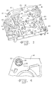
Fig. 1 is a perspective view of a transmission manifold made in accordance with the present invention; -
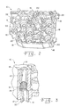
Fig. 2 is a perspective view of the transmission manifold shown inFig. 1 , illustrating the side opposite the side shown inFig. 1 ; -
Fig. 3 is a fragmentary cross-sectional view through opposed ports of a manifold in accordance with the present invention; and -
Fig. 4 is an enlarged perspective view of a port in a manifold in accordance with the present invention. - Before the embodiments of the invention are explained in detail, it is to be understood that the invention is not limited in its application to the details of construction and the arrangements of the components set forth in the following description or illustrated in the drawings. The invention is capable of other embodiments and of being practiced or being carried out in various ways. Also, it is understood that the phraseology and terminology used herein are for the purpose of description and should not be regarded as limiting. The use herein of "including", "comprising" and variations thereof is meant to encompass the items listed thereafter and equivalents thereof, as well as additional items and equivalents thereof.
- Referring now more specifically to the drawings and to
Fig. 1 in particular,numeral 10 designates an automobile transmission manifold in accordance with the present invention. It should be understood that the particular configuration of a transmission manifold shown in the drawings is merely exemplary in nature, and the present invention can be used for transmission manifolds having other shapes and configurations. Further, while a transmission manifold is one advantageous use for the present invention, it is contemplated that other structures also can benefit from the use and application of the present invention. - Manifold 10 is a body of material of low electrical conductivity, such as plastic, and has a
first face 12 and asecond face 14 on opposite sides thereof. At least one first hole orport 16 is provided as an opening infirst face 12. A plurality offirst ports 16 is shown inFig. 1 . At least one second hole orport 18 is provided as an opening insecond face 14. A plurality ofsecond ports 18 is shown inFig. 2 . It should be understood that more or fewerfirst ports 16 andsecond ports 18 can be used for a specific manifold configuration. -
First inserts 20 are disposed infirst ports 16, andsecond inserts 22 are provided insecond ports 18. Inserts 20 and 22 can be of different shapes, configurations and sizes as suitable for the port in which each is installed. Knurling or other surface treatments can be provided on outer surfaces ofinserts ports manifold 10 can be otherwise formed of substantially non-conductive material, such as plastic. - As seen most clearly in
Fig. 3 , at least onefirst port 16 and onesecond port 18 are disposed generally across from one another, and acontinuous passageway 24 is established fromfirst port 16 infirst face 12 tosecond port 18 insecond face 14. In the exemplary embodiment shown, thefirst port 16 andsecond port 18 defining the continuous passage are in axial non-alignment. - An electrically
conductive spring 26 is provided inpassage 24, betweenfirst insert 20 andsecond insert 22.Spring 26 in the exemplary embodiment is a coil spring with a relaxed length longer than the free space inpassage 24 between the inner ends ofinserts spring 24 is compressed betweeninsert 20 and insert 22 to provide continuous electrical contact with eachinsert 20 and insert 22 on opposite ends ofspring 26. - In the exemplary embodiment of
Fig. 3 ,ports spring 26 is retained betweenopposed inserts insert 22 but not with theother insert 20. - A manifold of the present invention can be made by a variety of manufacturing techniques and processes. In one suitable process,
manifold 10 is made by molding, during which the variousfirst ports 16 andsecond ports 18 are formed.First inserts 20 are secured infirst ports 16 during the molding process. Accordingly,first inserts 20 are secured in a fixture in the mold cavity, with the material formanifold 10 being molded thereabout. Such techniques are often referred to as overmolding. As the material formanifold 10 hardens or cures, intimate contact is established for securingfirst inserts 20 in thefirst ports 16 that are formed there around. - During the molding process,
second ports 18 also are formed. Second inserts 22 can be secured by post mold inserting insecond ports 18 aftermanifold 10 is removed from the mold in which molding occurs. A heated inserting process, using, for example, induction heating can be used. Theinsert 22 is heated by induction heating, and then forced intosecond port 18. It should be understood that heating processes other than induction heating can be used to heat an insert for insertion. The heated mass ofsecond insert 22 softens the material ofmanifold 10lining passage 24, allowing insertion and subsequent intimate contact between the manifold and the insert. - Each of the
first inserts 20 andsecond inserts 22 can be secured as described. However, it should be understood that a variety of techniques can be used. For example, some or all of thefirst inserts 20 can be secured inmanifold 10 by post mold insertion, using induction inserting other heated inserting process after the manifold is formed in a molding operation. For some uses of the present invention, other post mold inserting processes can be used, and may include pressing or inserting without heating. - To establish the necessary electrical continuity for a ground connection between
first face 12 andsecond face 14,spring 26 is inserted into at least one set of a first ports defining acontinuous passage 24 between afirst port 16 and asecond port 18. For example, after thefirst insert 20 is secured relative tofirst port 16, which may be by overmolding,spring 26 is inserted intosecond port 18. Assecond insert 22 is inserted intosecond port 18,spring 26 is encountered and compressed between and against the first andsecond inserts Fig. 3 ,spring 26 thereby establishes continuous electrical contact betweenfirst insert 20 andsecond insert 22. - Variations and modifications of the foregoing are within the scope of the present invention. It is understood that the invention disclosed and defined herein extends to all alternative combinations of two or more of the individual features mentioned or evident from the text and/or drawings. All of these different combinations constitute various alternative aspects of the present invention. The embodiments described herein explain the best modes known for practicing the invention and will enable others skilled in the art to utilize the invention. The claims are to be construed to include alternative embodiments to the extent permitted by the prior art.
- Various features of the invention are set forth in the following claims.
Claims (20)
- An electrically conductive assembly comprising:a low conductivity body having first and second faces with first and second ports in said first and second faces;a first electrically conductive element extending into said body from said first port;a second electrically conductive element extending into said body from said second port; andan electrically conductive spring within said body between and in electrically conductive contact with said first and second electrically conductive elements at opposite ends of said spring.
- The assembly of claim 1, said spring being a coil spring.
- The assembly of claim 1, said first and second electrically conductive elements being misaligned axially.
- The assembly of claim 3, said spring being a coil spring.
- The assembly of claim 1, said first and second electrically conductive elements being metal.
- The assembly of claim 5, said first and second electrically conductive elements being misaligned axially
- The assembly of claim 5, said spring being a coil spring.
- The assembly of claim 7, said first and second electrically conductive elements being in axial misalignment.
- A transmission manifold comprising:a low electrical conductivity body having a first face and a second face on opposite first and second sides of said body;a first port defined in said first face, a second port defined in said second face and a continuous passage through said body from said first port to said second port;a first electrically conductive insert extending into said passage from said first port;a second electrically conductive insert extending into said passage from said second port; andan electrically conductive spring disposed between and in electrical contact with said first and second inserts within said passage.
- The transmission manifold of claim 9, said first and second inserts being misaligned axially.
- The transmission manifold of claim 9, including a plurality of first inserts in a plurality of first ports on said first side of said body, and a plurality of second inserts in a plurality of said second ports on said second side of said body.
- The transmission manifold of claim 11 including only one said spring.
- A method for making a transmission manifold comprising:molding a transmission manifold body with first and second ports on opposite faces thereof, including forming one first port and one second port with a continuous passage therebetween;securing a first electrically conductive insert in one of the first and second ports;positioning an electrically conductive spring in electrically conductive contact with the first insert;securing a second electrically conductive insert in the other of the first and second ports;compressing the spring between the first and second inserts; andestablishing continuous simultaneous electrical contact between the spring and each the first insert and the second insert within the passage.
- The method of claim 13, at least one of said securing steps performed by over molding.
- The method of claim 13, at least one of said securing steps performed by post mold inserting.
- The method of claim 13, one of said securing steps performed by over molding and the other of said securing steps performed by heating and inserting the insert.
- The method of claim 16, said molding of said body forming said first and second ports in axial misalignment.
- The method of claim 17, including:forming a plurality of the first ports and a plurality of the second ports;securing a plurality of first conductive inserts in the first ports;securing a plurality of the second inserts in the second ports; andcompressing only one spring in a passage between one of said first inserts and one of said second inserts.
- The method of claim 13, said molding of said body forming said first and second ports in axial misalignment.
- The method of claim 13, including:forming a plurality of the first ports and a plurality of the second ports;securing a plurality of first conductive inserts in the first ports;securing a plurality of the second inserts in the second ports; andcompressing only one spring in a passageway between one of said first inserts and one of said second inserts.
Applications Claiming Priority (1)
| Application Number | Priority Date | Filing Date | Title |
|---|---|---|---|
| US11/640,553 US7754972B2 (en) | 2006-12-18 | 2006-12-18 | Grounded manifold and method for making the same |
Publications (2)
| Publication Number | Publication Date |
|---|---|
| EP1935606A1 true EP1935606A1 (en) | 2008-06-25 |
| EP1935606B1 EP1935606B1 (en) | 2010-09-15 |
Family
ID=39247002
Family Applications (1)
| Application Number | Title | Priority Date | Filing Date |
|---|---|---|---|
| EP07122111A Not-in-force EP1935606B1 (en) | 2006-12-18 | 2007-12-03 | Grounded manifold and method for making the same |
Country Status (3)
| Country | Link |
|---|---|
| US (1) | US7754972B2 (en) |
| EP (1) | EP1935606B1 (en) |
| DE (1) | DE602007009177D1 (en) |
Families Citing this family (1)
| Publication number | Priority date | Publication date | Assignee | Title |
|---|---|---|---|---|
| US9683379B2 (en) * | 2012-06-01 | 2017-06-20 | Time Manufacturing Company | Apparatuses and methods for providing high electrical resistance for aerial work platform components |
Citations (1)
| Publication number | Priority date | Publication date | Assignee | Title |
|---|---|---|---|---|
| EP0797008A2 (en) * | 1996-03-18 | 1997-09-24 | Eaton Corporation | Solenoid manifold assembly |
Family Cites Families (7)
| Publication number | Priority date | Publication date | Assignee | Title |
|---|---|---|---|---|
| US3135520A (en) * | 1960-01-12 | 1964-06-02 | John E Borah | Molded gasket with flexible metal insert |
| US3796623A (en) * | 1970-09-29 | 1974-03-12 | Farnam F Co | Method of making insulator gaskets |
| US5167512A (en) * | 1991-07-05 | 1992-12-01 | Walkup William B | Multi-chip module connector element and system |
| EP0616394A1 (en) * | 1993-03-16 | 1994-09-21 | Hewlett-Packard Company | Method and system for producing electrically interconnected circuits |
| CN1255686C (en) * | 1996-04-12 | 2006-05-10 | 日本发条株式会社 | Conductive contact unit system |
| JP4060919B2 (en) * | 1997-11-28 | 2008-03-12 | 富士通株式会社 | Electrical connection device, contact manufacturing method, and semiconductor test method |
| US7019222B2 (en) * | 2002-01-17 | 2006-03-28 | Ardent Concepts, Inc. | Compliant electrical contact assembly |
-
2006
- 2006-12-18 US US11/640,553 patent/US7754972B2/en not_active Expired - Fee Related
-
2007
- 2007-12-03 EP EP07122111A patent/EP1935606B1/en not_active Not-in-force
- 2007-12-03 DE DE602007009177T patent/DE602007009177D1/en active Active
Patent Citations (1)
| Publication number | Priority date | Publication date | Assignee | Title |
|---|---|---|---|---|
| EP0797008A2 (en) * | 1996-03-18 | 1997-09-24 | Eaton Corporation | Solenoid manifold assembly |
Also Published As
| Publication number | Publication date |
|---|---|
| US7754972B2 (en) | 2010-07-13 |
| DE602007009177D1 (en) | 2010-10-28 |
| US20080145606A1 (en) | 2008-06-19 |
| EP1935606B1 (en) | 2010-09-15 |
Similar Documents
| Publication | Publication Date | Title |
|---|---|---|
| KR101857172B1 (en) | Hybrid suspension arm for vehicle and manufacturing method thereof | |
| EP0976166B1 (en) | Piezoelectric actuator with a hollow profile | |
| US20100207001A1 (en) | Conductive And Isolated 2-Shot Tube Clamp | |
| JP5606775B2 (en) | Mating member | |
| WO2009138719A1 (en) | An insert kit and installation method | |
| US5839847A (en) | Molded article with captured fasteners | |
| EP0547767B1 (en) | A rotor for rotary electrical machinery | |
| EP0861139B1 (en) | Composite socket with double inserts | |
| CN101821912B (en) | Crimping die | |
| EP1935606B1 (en) | Grounded manifold and method for making the same | |
| CN104842500B (en) | Method and mold for producing openings in fiber composite parts | |
| JP2000208232A (en) | Manufacture of harness and metal mold used therefor | |
| WO2018197138A1 (en) | Multipoint control arm | |
| US8920901B2 (en) | Blow molded assembly with an attachment fastener portion, and method thereof | |
| US20040232607A1 (en) | Vibration-damping link and a method of manufacturing said link | |
| GB2343731A (en) | A method of manufacturing a cylindrical elastic mount | |
| CN110429447B (en) | Method for manufacturing connector | |
| KR102668183B1 (en) | Coil assembly and solenoid valve including the same | |
| US20130180975A1 (en) | Glow plug terminal and glow plug | |
| WO1997025172A1 (en) | A method of insert-casting an open thread-inser/bush upon casting, press casting, injection moulding of details and a device for accomplishment of the method | |
| US11078958B1 (en) | Compression limiter | |
| JP2006069233A (en) | Manufacturing method of stabilizer bar with rubber bush | |
| US7052224B2 (en) | Fastener assembly with molded internal helical flutes | |
| JP4164553B2 (en) | Molding method of delivery pipe mounting bracket member | |
| KR20080044407A (en) | Manufacturing method and apparatus for insert-type bushing of a vehicle |
Legal Events
| Date | Code | Title | Description |
|---|---|---|---|
| PUAI | Public reference made under article 153(3) epc to a published international application that has entered the european phase |
Free format text: ORIGINAL CODE: 0009012 |
|
| AK | Designated contracting states |
Kind code of ref document: A1 Designated state(s): AT BE BG CH CY CZ DE DK EE ES FI FR GB GR HU IE IS IT LI LT LU LV MC MT NL PL PT RO SE SI SK TR |
|
| AX | Request for extension of the european patent |
Extension state: AL BA HR MK RS |
|
| 17P | Request for examination filed |
Effective date: 20081211 |
|
| AKX | Designation fees paid |
Designated state(s): DE ES FR GB IT |
|
| GRAP | Despatch of communication of intention to grant a patent |
Free format text: ORIGINAL CODE: EPIDOSNIGR1 |
|
| GRAS | Grant fee paid |
Free format text: ORIGINAL CODE: EPIDOSNIGR3 |
|
| GRAA | (expected) grant |
Free format text: ORIGINAL CODE: 0009210 |
|
| AK | Designated contracting states |
Kind code of ref document: B1 Designated state(s): DE ES FR GB IT |
|
| REG | Reference to a national code |
Ref country code: GB Ref legal event code: FG4D |
|
| REF | Corresponds to: |
Ref document number: 602007009177 Country of ref document: DE Date of ref document: 20101028 Kind code of ref document: P |
|
| PG25 | Lapsed in a contracting state [announced via postgrant information from national office to epo] |
Ref country code: IT Free format text: LAPSE BECAUSE OF FAILURE TO SUBMIT A TRANSLATION OF THE DESCRIPTION OR TO PAY THE FEE WITHIN THE PRESCRIBED TIME-LIMIT Effective date: 20100915 |
|
| PG25 | Lapsed in a contracting state [announced via postgrant information from national office to epo] |
Ref country code: ES Free format text: LAPSE BECAUSE OF FAILURE TO SUBMIT A TRANSLATION OF THE DESCRIPTION OR TO PAY THE FEE WITHIN THE PRESCRIBED TIME-LIMIT Effective date: 20101226 |
|
| PLBE | No opposition filed within time limit |
Free format text: ORIGINAL CODE: 0009261 |
|
| STAA | Information on the status of an ep patent application or granted ep patent |
Free format text: STATUS: NO OPPOSITION FILED WITHIN TIME LIMIT |
|
| 26N | No opposition filed |
Effective date: 20110616 |
|
| REG | Reference to a national code |
Ref country code: FR Ref legal event code: ST Effective date: 20110831 |
|
| REG | Reference to a national code |
Ref country code: DE Ref legal event code: R097 Ref document number: 602007009177 Country of ref document: DE Effective date: 20110616 |
|
| PG25 | Lapsed in a contracting state [announced via postgrant information from national office to epo] |
Ref country code: FR Free format text: LAPSE BECAUSE OF NON-PAYMENT OF DUE FEES Effective date: 20110103 |
|
| REG | Reference to a national code |
Ref country code: DE Ref legal event code: R119 Ref document number: 602007009177 Country of ref document: DE Effective date: 20110701 |
|
| PG25 | Lapsed in a contracting state [announced via postgrant information from national office to epo] |
Ref country code: DE Free format text: LAPSE BECAUSE OF NON-PAYMENT OF DUE FEES Effective date: 20110701 |
|
| GBPC | Gb: european patent ceased through non-payment of renewal fee |
Effective date: 20111203 |
|
| PG25 | Lapsed in a contracting state [announced via postgrant information from national office to epo] |
Ref country code: GB Free format text: LAPSE BECAUSE OF NON-PAYMENT OF DUE FEES Effective date: 20111203 |