EP1935531A2 - Process to cast seal slots in turbine vane shrouds - Google Patents
Process to cast seal slots in turbine vane shrouds Download PDFInfo
- Publication number
- EP1935531A2 EP1935531A2 EP07254616A EP07254616A EP1935531A2 EP 1935531 A2 EP1935531 A2 EP 1935531A2 EP 07254616 A EP07254616 A EP 07254616A EP 07254616 A EP07254616 A EP 07254616A EP 1935531 A2 EP1935531 A2 EP 1935531A2
- Authority
- EP
- European Patent Office
- Prior art keywords
- core assembly
- refractory
- turbine engine
- airfoils
- slot
- Prior art date
- Legal status (The legal status is an assumption and is not a legal conclusion. Google has not performed a legal analysis and makes no representation as to the accuracy of the status listed.)
- Withdrawn
Links
Images
Classifications
-
- B—PERFORMING OPERATIONS; TRANSPORTING
- B22—CASTING; POWDER METALLURGY
- B22C—FOUNDRY MOULDING
- B22C9/00—Moulds or cores; Moulding processes
- B22C9/10—Cores; Manufacture or installation of cores
- B22C9/103—Multipart cores
-
- B—PERFORMING OPERATIONS; TRANSPORTING
- B22—CASTING; POWDER METALLURGY
- B22C—FOUNDRY MOULDING
- B22C9/00—Moulds or cores; Moulding processes
- B22C9/02—Sand moulds or like moulds for shaped castings
- B22C9/04—Use of lost patterns
-
- B—PERFORMING OPERATIONS; TRANSPORTING
- B22—CASTING; POWDER METALLURGY
- B22C—FOUNDRY MOULDING
- B22C9/00—Moulds or cores; Moulding processes
- B22C9/10—Cores; Manufacture or installation of cores
-
- B—PERFORMING OPERATIONS; TRANSPORTING
- B22—CASTING; POWDER METALLURGY
- B22D—CASTING OF METALS; CASTING OF OTHER SUBSTANCES BY THE SAME PROCESSES OR DEVICES
- B22D25/00—Special casting characterised by the nature of the product
-
- F—MECHANICAL ENGINEERING; LIGHTING; HEATING; WEAPONS; BLASTING
- F05—INDEXING SCHEMES RELATING TO ENGINES OR PUMPS IN VARIOUS SUBCLASSES OF CLASSES F01-F04
- F05B—INDEXING SCHEME RELATING TO WIND, SPRING, WEIGHT, INERTIA OR LIKE MOTORS, TO MACHINES OR ENGINES FOR LIQUIDS COVERED BY SUBCLASSES F03B, F03D AND F03G
- F05B2230/00—Manufacture
- F05B2230/20—Manufacture essentially without removing material
- F05B2230/21—Manufacture essentially without removing material by casting
-
- F—MECHANICAL ENGINEERING; LIGHTING; HEATING; WEAPONS; BLASTING
- F05—INDEXING SCHEMES RELATING TO ENGINES OR PUMPS IN VARIOUS SUBCLASSES OF CLASSES F01-F04
- F05B—INDEXING SCHEME RELATING TO WIND, SPRING, WEIGHT, INERTIA OR LIKE MOTORS, TO MACHINES OR ENGINES FOR LIQUIDS COVERED BY SUBCLASSES F03B, F03D AND F03G
- F05B2240/00—Components
- F05B2240/10—Stators
- F05B2240/11—Shroud seal segments
-
- F—MECHANICAL ENGINEERING; LIGHTING; HEATING; WEAPONS; BLASTING
- F05—INDEXING SCHEMES RELATING TO ENGINES OR PUMPS IN VARIOUS SUBCLASSES OF CLASSES F01-F04
- F05B—INDEXING SCHEME RELATING TO WIND, SPRING, WEIGHT, INERTIA OR LIKE MOTORS, TO MACHINES OR ENGINES FOR LIQUIDS COVERED BY SUBCLASSES F03B, F03D AND F03G
- F05B2240/00—Components
- F05B2240/57—Seals
- F05B2240/572—Leaf seals
Definitions
- the present invention is directed to a process for casting seal slots in turbine engine components, such as turbine vane shrouds, and to a cast turbine engine component having seal slots for improving the sealing mechanisms in the turbine engine component and thereby minimizing leakage from the flow path out through the vane shrouds.
- vanes are typically cast and machined as separate segments, containing two or more airfoils, with feather seals installed in slots along the vane shrouds in order to minimize the leakage between the segments.
- the inner or outer shrouds may be sliced between the airfoils at regular intervals during the final machining operations, or cast with a slip joint which allows for relative motion between the one end of the vane and the mating shroud.
- a process for casting a turbine engine component broadly comprises the steps of: placing a refractory core assembly comprising two intersecting plates in a die; encapsulating the refractory core assembly in a wax pattern having the form of the turbine engine component; forming a ceramic shell mold about the wax pattern; removing the wax pattern; and pouring molten material into the ceramic shell mold to form the turbine engine component.
- a refractory metal core assembly for use in casting a seal slot in a turbine vane shroud.
- the refractory metal core assembly broadly comprises a first core plate having a first surface and a second surface opposed to the first surface; a first slot in the second surface; and a second core plate having a mating portion which fits into the first slot.
- a turbine engine component comprising an inner shroud ring, an outer shroud ring, a plurality of airfoils extending between the inner and outer shroud rings, and at least one as-cast slot and at least one as cast split line in one of the shroud rings.
- the present invention is directed to process for providing a turbine engine component configuration that maximizes durability and minimizes leakage.
- the process described herein can be used with a variety of turbine flow path alloys, full ring or segmented vanes.
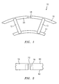
- a vane ring 10 such as that shown in FIG. 1 has a plurality of airfoils 12 which extend between an inner shroud ring 14 and an outer shroud ring 16.
- the vane ring 10 is typically annular in shape.
- the vane ring 10 can be produced using an equiaxed alloy, a directionally solidified alloy, or a single crystal alloy. A combination of any two of these types of alloys can be used to produce a bi-cast or dual alloy process.
- the individual airfoils 12 may be first cast from a single crystal material, such as a single crystal nickel based superalloy, and then the shrouds 14 and 16 may be cast around the airfoils 12 using an equiaxed or directionally solidified alloy having a lower melting temperature than the single crystal alloy used for the airfoils.
- the use of such a bi-cast process is desirable in that it allows for optimization of the crystal orientation within the airfoils 12 and maximizes temperature capability.
- the airfoils 12 may be solid; however, for high temperature applications, the airfoils 12 may be cooled and therefore contain internal cavities (not shown). The internal cavities may be produced using refractory metal cores, conventional ceramic cores, or any other suitable technique known in the art.
- the bi-cast process was used in a way that locked the airfoils within one of the shrouds, typically the inner shroud, but allowed the other end of the airfoil to move and grow radially during engine operation. Without allowing this degree of freedom, the airfoils and the shroud rings could not withstand the thermally induced stresses. However, this loose joint, usually produced by the application of a ceramic or oxide layer during the casting process, results in a significant leak path around the edge of every airfoil.
- An alternative way to address the thermal stress problem in full hoop vane rings is to incorporate one or more slots in one of the shroud rings, typically the outer shroud ring. In the past, this was done during final machining by a wire EDM or conventional machining process that slices the shroud at regular intervals, either between all airfoils or between multiple airfoil groups. The slot would be sized to allow for closure at the maximum temperature condition. Such a method could be used either for a full vane ring of a homogeneous alloy produced by a single casting operation or for a bi-cast vane ring as previously described.
- both ends of the airfoils can now be locked within the shroud during the casting process (by omitting the slip joint between the ends of the airfoils and the shrouds).
- This allows for no movement of the airfoils independent of the shrouds (for thermal stress relief), but it also eliminates the large leak path around each airfoil.
- the slots in the outer shroud become the thermal stress relief mechanism, allowing the airfoils to grow outward and the shroud to bow at controlled regular intervals. However, these slots also become the primary leak path for this vane ring.
- one or more as-cast feather seal pockets or slots 18 may be produced in a wall 20 of the outer shroud ring 16 in between two adjacent airfoils 12.
- Each pocket 18 may be cast integrally with a shroud split line 22 using a refractory metal core assembly 30 in accordance with the present invention.
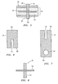
- the refractory metal core assembly 30 used to produce the pocket 18 and the intersecting shroud split line 22 is shown in FIGS. 3 - 8 .
- the refractory metal core assembly 30 is formed from two thin plates 32 and 34. As shown in FIGS. 3 - 5 and 8 , the thin plates 32 and 34 are constructed so they can be interlocked perpendicular to each other. As can be seen from FIG.7 , the plate 32 has a first surface 80 and a second surface 82 opposed to the first surface 80. A slot 50 is cut into the second surface 82. As can be seen from FIG. 6 , the plate 34 has a first surface 84 and a second surface 86 opposed to the first surface 84. A slot 52 is cut or formed into the second surface 86. The slots 50 and 52 form mating portions which allow the plates 32 and 34 to be interlocked perpendicular to each other when joined together.
- Each of the plates 32 and 34 may be formed from a refractory metal or refractory metal alloy. While the plates 32 and 34 may typically be formed from molybdenum or a molybdenum alloy, they could be formed from any suitable refractory material. If desired, each plate 32 and 34 may have a thin ceramic coating applied to the base refractory metal, refractory metal alloy, or refractory material forming the respective plate. Each of the plates 32 and 34 is solid.
- the plate 32 has a circular aperture or locating feature 54 which allows the plate and the core assembly to be secured in a wax die. Still further, the plate 32 forming the split in the shroud ring is the longer of the two plates 32 and 34.
- the plate 32 creates a shroud split line 22 that runs the entire axial length of the shroud ring wall 20.
- the plate 34 that forms the seal slot or pocket 18 is the shorter of the two plates. It preferably creates a slot or pocket 18 that runs from a top face 62 of the shroud ring 16 and bottoms out before an aft end 64 of the shroud ring 16. Forming a seal pocket 18 that is closed at one end is important to minimizing the leakage down the shroud ring 16.
- the pocket 18 is typically open for feather seal installation.
- the engine assembly could include an upstream mating part in contact with the top of the vane ring shroud 16 that would cover the top of the pocket 18 to assure the seals are retained, and to close this leak path.
- the seal pocket 18 could be produced as an as-cast feature without the split lines 22 included using one piece core consisting of plate 34 only.
- the split line could then be produced as a more precisely controlled machined feature.
- the split line could be included but cast undersized, using a thinner plate 32, to providing better core locating control during the casting process, while still taking advantage of the more precise machining process to create the final split line dimension.
- This configuration when the width of the split line 22 is minimized based on predicted thermal growth, and the dimensions of the seal pocket 18 are optimized based on the feather seal design, provides for a minimum amount of leakage through the shroud wall, while still allowing for relief of the thermal stress. Further optimization could result by reducing the number of slot split lines 22, rather than including them between all of the airfoils. As opposed to attempting to EDM the seal pockets 18, producing them as a cast feature greatly reduces the cost, lead time and variability. In addition the casting process will result in a better surface finish with the seal pocket 18, which is important in maximizing the sealing capability of the feather seal. Since the shroud split lines 22 are formed at the same time as the seal pockets, a subsequent machining operation is saved.
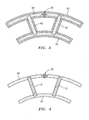
- one or more refractory metal core assemblies 30 are first installed in a shroud cavity 36 of a wax die 38 as shown in FIGS. 4 and 5 .
- the wax die 38 may be formed from any suitable material known in the art.
- each refractory metal core assembly 30 may be held during the wax injection process by the locating feature 54. Wax may be injected into the die 38 using any suitable technique known in the art. After the wax injection process has been completed, a wax pattern 40, such as that shown in FIGS. 4 and 5 is formed.
- the wax pattern 40 which is formed is in the shape of the airfoils 12 and the shroud rings 14 and 16 to be cast.
- the refractory metal core assembly 30 is substantially embedded within the wax pattern 40. There are portions 58 and 60 of each refractory metal core assembly 30 that extend beyond the wax pattern 40. These portions are exposed during the dipping process used to form the wax pattern 40.
- a ceramic shell 42 is formed about the wax pattern 40.
- the ceramic shell 42 may be formed using any suitable technique known in the art such as with a dipping process. Additionally, the ceramic shell 42 may be formed from any suitable ceramic material known in the art.
- the ceramic shell 42 serves to secure each refractory metal core assembly 30 after the mold is dewaxed, cured, and throughout the pouring and solidification of the metal alloy(s) forming the airfoils 12 and the shroud rings 14 and 16.
- the molten metal alloy material used to form the airfoils 12 and the shroud rings 14 and 16 may be poured into the ceramic mold using any suitable technique known in the art.
- a bi-cast process two types of alloys with different melting temperatures are used to produce a dual alloy vane ring.
- the individual airfoils 12 may be first cast from a single crystal material, such as a single crystal nickel based superalloy. After solidification, the individual airfoils may be removed from the ceramic shell and processed through normal casting finishing operations. A set of airfoils may then be placed in a separate die that locates them in a ring for wax injection of the shroud forms.
- the ceramic mold, with the cast airfoils imbedded are brought to the mold pre-heat temperature, and the shrouds 14 and 16 may be cast around the airfoils 12 using an equiaxed or directionally solidified alloy having a lower melting temperature than the single crystal alloy used for the airfoils.
- each refractory metal core assembly 30 may be removed using any suitable technique known in the art, leaving one or more pockets 18 and one or more split line 22.
- the refractory metal cores may be removed from the solidified vanes rings using an acid leach process.
- the vane ring configuration formed by the process of the present invention will have significantly lower leakage than the state-of-the art bi-cast methods currently available due to elimination of the irregular, unsealed operating gap around the perimeter of the airfoils as they pass through the shroud, replacing that gap with a controlled sealed slot.
Landscapes
- Engineering & Computer Science (AREA)
- Mechanical Engineering (AREA)
- Turbine Rotor Nozzle Sealing (AREA)
- Molds, Cores, And Manufacturing Methods Thereof (AREA)
Abstract
Description
- The present invention is directed to a process for casting seal slots in turbine engine components, such as turbine vane shrouds, and to a cast turbine engine component having seal slots for improving the sealing mechanisms in the turbine engine component and thereby minimizing leakage from the flow path out through the vane shrouds.
- In order to avoid the large thermally induced hoop stresses in outer and inner shrouds of full hoop turbine vane rings, vanes are typically cast and machined as separate segments, containing two or more airfoils, with feather seals installed in slots along the vane shrouds in order to minimize the leakage between the segments. When the use of a continuous vane ring is possible, the inner or outer shrouds may be sliced between the airfoils at regular intervals during the final machining operations, or cast with a slip joint which allows for relative motion between the one end of the vane and the mating shroud. In a full vane ring configuration, the incorporation of feather seals is not practical due to the lack of access to the side faces, or the long cycle times, complexity, and high cost of producing a feather seal slot using an EDM process (plunging the electrode from one of the axial surfaces).
- The ability to produce the shroud gaps and the imbedded seal slots as an as-cast feature could provide significant lead-time and cost reductions. In addition, a cast slot will have a better surface finish than one produced by EDM, which would also contribute to minimizing leakage.
- The use of ceramic cores to cast a seal slot in the shroud of a typical vane ring would not produce much success. The small, thin size required for both the main body of the core and any locating or holding feature would not result in sufficient strength to produce acceptable casting yields.
- In accordance with the present invention, there is provided a process for casting a turbine engine component. The process broadly comprises the steps of: placing a refractory core assembly comprising two intersecting plates in a die; encapsulating the refractory core assembly in a wax pattern having the form of the turbine engine component; forming a ceramic shell mold about the wax pattern; removing the wax pattern; and pouring molten material into the ceramic shell mold to form the turbine engine component.
- Further, in accordance with the present invention, there is provided a refractory metal core assembly for use in casting a seal slot in a turbine vane shroud. The refractory metal core assembly broadly comprises a first core plate having a first surface and a second surface opposed to the first surface; a first slot in the second surface; and a second core plate having a mating portion which fits into the first slot.
- Still further, in accordance with the present invention, there is provided a turbine engine component comprising an inner shroud ring, an outer shroud ring, a plurality of airfoils extending between the inner and outer shroud rings, and at least one as-cast slot and at least one as cast split line in one of the shroud rings.
- Other details of the process for casting seal slots in turbine vane shrouds, as well as other advantages attendant thereto, are set forth in the following detailed description and the accompanying drawings wherein like reference numerals depict like elements.
-
-
FIG. 1 illustrates a portion of a vane ring used in a turbine engine component; -
FIG. 2 illustrates a top view of a portion of the vane ring ofFIG. 1 ; -
FIG. 3 illustrates a sectional view of a portion of a vane ring mold after shell dip; -
FIG. 4 is a sectional view of a refractory metal core assembly for forming a cast seal slot embedded within a wax pattern within a die; -
FIG. 5 is an enlarged view of the embedded refractory metal core assembly ofFIG. 4 ; -
FIG. 6 shows a first plate used in the refractory metal core assembly of the present invention; -
FIG. 7 shows a second plate used in the refractory metal core assembly of the present invention; and -
FIG. 8 illustrates a top view of the refractory core assembly of the present invention. - The present invention is directed to process for providing a turbine engine component configuration that maximizes durability and minimizes leakage. The process described herein can be used with a variety of turbine flow path alloys, full ring or segmented vanes.
- A
vane ring 10 such as that shown inFIG. 1 has a plurality ofairfoils 12 which extend between aninner shroud ring 14 and anouter shroud ring 16. Thevane ring 10 is typically annular in shape. Thevane ring 10 can be produced using an equiaxed alloy, a directionally solidified alloy, or a single crystal alloy. A combination of any two of these types of alloys can be used to produce a bi-cast or dual alloy process. For a useful bi-cast configuration, theindividual airfoils 12 may be first cast from a single crystal material, such as a single crystal nickel based superalloy, and then theshrouds airfoils 12 using an equiaxed or directionally solidified alloy having a lower melting temperature than the single crystal alloy used for the airfoils. The use of such a bi-cast process is desirable in that it allows for optimization of the crystal orientation within theairfoils 12 and maximizes temperature capability. Theairfoils 12 may be solid; however, for high temperature applications, theairfoils 12 may be cooled and therefore contain internal cavities (not shown). The internal cavities may be produced using refractory metal cores, conventional ceramic cores, or any other suitable technique known in the art. - In the past, the bi-cast process was used in a way that locked the airfoils within one of the shrouds, typically the inner shroud, but allowed the other end of the airfoil to move and grow radially during engine operation. Without allowing this degree of freedom, the airfoils and the shroud rings could not withstand the thermally induced stresses. However, this loose joint, usually produced by the application of a ceramic or oxide layer during the casting process, results in a significant leak path around the edge of every airfoil.
- An alternative way to address the thermal stress problem in full hoop vane rings is to incorporate one or more slots in one of the shroud rings, typically the outer shroud ring. In the past, this was done during final machining by a wire EDM or conventional machining process that slices the shroud at regular intervals, either between all airfoils or between multiple airfoil groups. The slot would be sized to allow for closure at the maximum temperature condition. Such a method could be used either for a full vane ring of a homogeneous alloy produced by a single casting operation or for a bi-cast vane ring as previously described. With the addition of machined slots in one of the shrouds, both ends of the airfoils can now be locked within the shroud during the casting process (by omitting the slip joint between the ends of the airfoils and the shrouds). This allows for no movement of the airfoils independent of the shrouds (for thermal stress relief), but it also eliminates the large leak path around each airfoil. The slots in the outer shroud become the thermal stress relief mechanism, allowing the airfoils to grow outward and the shroud to bow at controlled regular intervals. However, these slots also become the primary leak path for this vane ring.
- Referring now to
FIG. 2 , in accordance with the process of the present invention, one or more as-cast feather seal pockets orslots 18 may be produced in awall 20 of theouter shroud ring 16 in between twoadjacent airfoils 12. Eachpocket 18 may be cast integrally with ashroud split line 22 using a refractorymetal core assembly 30 in accordance with the present invention. - The refractory
metal core assembly 30 used to produce thepocket 18 and the intersectingshroud split line 22 is shown inFIGS. 3 - 8 . The refractorymetal core assembly 30 is formed from twothin plates FIGS. 3 - 5 and8 , thethin plates FIG.7 , theplate 32 has afirst surface 80 and asecond surface 82 opposed to thefirst surface 80. Aslot 50 is cut into thesecond surface 82. As can be seen fromFIG. 6 , theplate 34 has afirst surface 84 and asecond surface 86 opposed to thefirst surface 84. Aslot 52 is cut or formed into thesecond surface 86. Theslots plates - Each of the
plates plates plate plates - The
plate 32 has a circular aperture or locatingfeature 54 which allows the plate and the core assembly to be secured in a wax die. Still further, theplate 32 forming the split in the shroud ring is the longer of the twoplates plate 32 creates ashroud split line 22 that runs the entire axial length of theshroud ring wall 20. Theplate 34 that forms the seal slot orpocket 18 is the shorter of the two plates. It preferably creates a slot orpocket 18 that runs from atop face 62 of theshroud ring 16 and bottoms out before anaft end 64 of theshroud ring 16. Forming aseal pocket 18 that is closed at one end is important to minimizing the leakage down theshroud ring 16. Thepocket 18 is typically open for feather seal installation. The engine assembly could include an upstream mating part in contact with the top of thevane ring shroud 16 that would cover the top of thepocket 18 to assure the seals are retained, and to close this leak path. - As an alternative approach, to assure a tighter control of the shroud split
line 22, theseal pocket 18 could be produced as an as-cast feature without the split lines 22 included using one piece core consisting ofplate 34 only. The split line could then be produced as a more precisely controlled machined feature. Alternatively, the split line could be included but cast undersized, using athinner plate 32, to providing better core locating control during the casting process, while still taking advantage of the more precise machining process to create the final split line dimension. - This configuration, when the width of the
split line 22 is minimized based on predicted thermal growth, and the dimensions of theseal pocket 18 are optimized based on the feather seal design, provides for a minimum amount of leakage through the shroud wall, while still allowing for relief of the thermal stress. Further optimization could result by reducing the number of slot splitlines 22, rather than including them between all of the airfoils. As opposed to attempting to EDM the seal pockets 18, producing them as a cast feature greatly reduces the cost, lead time and variability. In addition the casting process will result in a better surface finish with theseal pocket 18, which is important in maximizing the sealing capability of the feather seal. Since the shroud splitlines 22 are formed at the same time as the seal pockets, a subsequent machining operation is saved. - In order to form a turbine engine component such as that shown in
FIGS. 1 and 2 , one or more refractorymetal core assemblies 30 are first installed in ashroud cavity 36 of awax die 38 as shown inFIGS. 4 and5 . The wax die 38 may be formed from any suitable material known in the art. After being positioned in theshroud cavity 36 of the wax die, each refractorymetal core assembly 30 may be held during the wax injection process by the locatingfeature 54. Wax may be injected into the die 38 using any suitable technique known in the art. After the wax injection process has been completed, awax pattern 40, such as that shown inFIGS. 4 and5 is formed. As can be seen from these figures, thewax pattern 40 which is formed is in the shape of theairfoils 12 and the shroud rings 14 and 16 to be cast. Also, as can be seen from these figures, the refractorymetal core assembly 30 is substantially embedded within thewax pattern 40. There areportions metal core assembly 30 that extend beyond thewax pattern 40. These portions are exposed during the dipping process used to form thewax pattern 40. - Referring now to
FIG. 3 , aceramic shell 42 is formed about thewax pattern 40. Theceramic shell 42 may be formed using any suitable technique known in the art such as with a dipping process. Additionally, theceramic shell 42 may be formed from any suitable ceramic material known in the art. Theceramic shell 42 serves to secure each refractorymetal core assembly 30 after the mold is dewaxed, cured, and throughout the pouring and solidification of the metal alloy(s) forming theairfoils 12 and the shroud rings 14 and 16. - After de-waxing and curing, the molten metal alloy material used to form the
airfoils 12 and the shroud rings 14 and 16 may be poured into the ceramic mold using any suitable technique known in the art. When a bi-cast process is preferred, two types of alloys with different melting temperatures are used to produce a dual alloy vane ring. For one bi-cast configuration, theindividual airfoils 12 may be first cast from a single crystal material, such as a single crystal nickel based superalloy. After solidification, the individual airfoils may be removed from the ceramic shell and processed through normal casting finishing operations. A set of airfoils may then be placed in a separate die that locates them in a ring for wax injection of the shroud forms. Subsequent to the typical ceramic shell dipping process, and the wax burn out operation, the ceramic mold, with the cast airfoils imbedded, are brought to the mold pre-heat temperature, and theshrouds airfoils 12 using an equiaxed or directionally solidified alloy having a lower melting temperature than the single crystal alloy used for the airfoils. - After the
airfoils 12 and the shroud rings 14 and 16 have been formed, each refractorymetal core assembly 30 may be removed using any suitable technique known in the art, leaving one ormore pockets 18 and one ormore split line 22. The refractory metal cores may be removed from the solidified vanes rings using an acid leach process. - While the present invention has been described in the context of forming the split lines 22 and
pockets 18 in theouter shroud ring 16, one could form the split lines 22 and thepockets 18 in theinner shroud ring 14 if desired. - The vane ring configuration formed by the process of the present invention will have significantly lower leakage than the state-of-the art bi-cast methods currently available due to elimination of the irregular, unsealed operating gap around the perimeter of the airfoils as they pass through the shroud, replacing that gap with a controlled sealed slot.
Claims (23)
- A process for casting a turbine engine component comprising the steps of:placing a refractory core assembly (30) comprising at least one plate in a die (38);encapsulating said refractory core assembly (30) in a wax pattern (40) having the form of said turbine engine component;forming a ceramic shell mold (42) about said wax pattern (40);removing said wax pattern (40); andpouring molten material into said ceramic shell mold (42) to form said turbine engine component.
- The process of claim 1, wherein said refractory core assembly placing step comprises placing a refractory core assembly (30) comprising two intersecting plates (32, 34) in said die (38) and further comprising removing said refractory core assembly (30) after said molten material has solidified so as to form a split line (22) and a slot (18) in a wall of a portion of said turbine engine component.
- The process of claim 2, wherein said removing step comprises removing said refractory core assembly (30) using an acid leach operation.
- The process of any preceding claim, further comprising providing said refractory core assembly (30) with a locking feature and securing said refractory core assembly (30) in said die (38) using said locking feature and placing a plurality of refractory core assemblies (30) in said die (38).
- The process of any preceding claim, further comprising placing said refractory core assembly (30) in a portion of said die (38) to be used to form an outer shroud ring (16) and forming said refractory core assembly (30) from a first plate (32) having a first length and a second plate (34) having a second length shorter than said first length.
- The process of any preceding claim, further comprising removing said at least one plate (32, 34) so as to form at least one seal slot (18) and solidifying said material so as to form continuous cast shroud rings with no split lines.
- The process of any preceding claim, wherein said pouring step comprises pouring a first molten material into said ceramic shell mold (42) to form a plurality of airfoils (12).
- The process of claim 7, wherein said first molten material pouring step comprises pouring a single crystal nickel based superalloy.
- The process of claim 7 or 8, further comprising:removing said airfoils (12) from said ceramic shell mold (42);placing said airfoils (12) in a separate die;forming a wax pattern in the form of a plurality of shrouds;forming a ceramic shell mold around said wax pattern; andpouring a second molten material into said mold.
- The process of claim 9, wherein said second molten material pouring step comprises pouring a molten material different from said first molten material.
- The process of claim 9 or 10, wherein said second molten material comprises pouring a molten material selected from the group consisting of an equiaxed alloy, a directionally solidified alloy, and a single crystal alloy.
- A refractory metal core assembly (30) for use in casting a seal slot (18) in a turbine vane shroud, said refractory metal core assembly (30) comprising:a first core plate (32) having a first surface (80) and a second surface (82) opposed to said first surface (80);a first slot (50) in said second surface (82); anda second core plate (34) having a mating portion (52) which fits into said first slot (50).
- The refractory metal core assembly of claim 12, wherein said second core plate (34) has a first surface (84) and a second surface (86) opposed to said first surface (84) and said mating portion comprises a second slot (52) in said second surface (86) of said second core plate (34) and wherein each of said slots (50, 52) is rectangular in shape.
- The refractory metal core assembly according to claim 12 or 13, wherein each of said plates (32, 34) is solid and rectangular in shape, wherein said first core plate (32) has a hole (54) in a portion remote from said first slot (50) and wherein said first core plate (32) and said second core plate (34) are perpendicular to each other when joined together.
- The refractory metal core assembly according to any of claims 12 to 14, wherein each of said first core plate (32) and said second core plate (34) is formed from at least one of a refractory metal and a refractory metal alloy and further comprising a coating on each of said plates (32, 34).
- The refractory metal core assembly according to claim 15, wherein said coating is a ceramic coating.
- A turbine engine component comprising:an inner shroud ring (14);an outer shroud ring (16);a plurality of airfoils (12) extending between said inner and outer shroud rings (14, 16); andat least one as-cast slot (18) and at least one split line (22) in one of said shroud rings (14, 16).
- The turbine engine component of claim 17, wherein each said split line (22) is an as-cast split line.
- The turbine engine component according to claim 17 or 18, wherein said at least one as-cast slot (18) and said at least one split line (22) is formed in said outer shroud ring (16) and wherein each said as-cast slot (18) and each said as-cast split line (22) is located between adjacent ones of said airfoils (12).
- The turbine engine component according to claim 17, 18 or 19, wherein said airfoils (12) are formed from a first material and said shroud rings (14, 16) are formed from a second material different from said first material.
- The turbine engine component according to claim 20, wherein said airfoils (20) are formed from a single crystal alloy and wherein said shroud rings (14, 16) are formed from one of an equiaxed alloy and a directionally solidified alloy.
- The turbine engine component according to any of claims 17 to 21, wherein said shroud rings (14, 16) and said airfoils (12) are each formed are formed from the same alloy and wherein said alloy is selected from the group consisting of an equiaxed alloy, a directionally solidified alloy, and a single crystal alloy.
- The turbine engine component according to any of claims 17 to 22, wherein each said split line (22) extends an entire axial length of a wall of the shroud ring (14, 16) and wherein each said slot (18) is open at one end and closed at a second end.
Priority Applications (2)
| Application Number | Priority Date | Filing Date | Title |
|---|---|---|---|
| EP11159077A EP2340900A3 (en) | 2006-12-14 | 2007-11-28 | Process to cast seal slots in turbine vane shrouds |
| EP11159078.2A EP2335846B1 (en) | 2006-12-14 | 2007-11-28 | Refractory metal core for cast seal slots in turbine vane shrouds |
Applications Claiming Priority (1)
| Application Number | Priority Date | Filing Date | Title |
|---|---|---|---|
| US11/639,455 US7967555B2 (en) | 2006-12-14 | 2006-12-14 | Process to cast seal slots in turbine vane shrouds |
Publications (2)
| Publication Number | Publication Date |
|---|---|
| EP1935531A2 true EP1935531A2 (en) | 2008-06-25 |
| EP1935531A3 EP1935531A3 (en) | 2008-08-06 |
Family
ID=39126196
Family Applications (3)
| Application Number | Title | Priority Date | Filing Date |
|---|---|---|---|
| EP11159078.2A Ceased EP2335846B1 (en) | 2006-12-14 | 2007-11-28 | Refractory metal core for cast seal slots in turbine vane shrouds |
| EP07254616A Withdrawn EP1935531A3 (en) | 2006-12-14 | 2007-11-28 | Process to cast seal slots in turbine vane shrouds |
| EP11159077A Withdrawn EP2340900A3 (en) | 2006-12-14 | 2007-11-28 | Process to cast seal slots in turbine vane shrouds |
Family Applications Before (1)
| Application Number | Title | Priority Date | Filing Date |
|---|---|---|---|
| EP11159078.2A Ceased EP2335846B1 (en) | 2006-12-14 | 2007-11-28 | Refractory metal core for cast seal slots in turbine vane shrouds |
Family Applications After (1)
| Application Number | Title | Priority Date | Filing Date |
|---|---|---|---|
| EP11159077A Withdrawn EP2340900A3 (en) | 2006-12-14 | 2007-11-28 | Process to cast seal slots in turbine vane shrouds |
Country Status (2)
| Country | Link |
|---|---|
| US (3) | US7967555B2 (en) |
| EP (3) | EP2335846B1 (en) |
Cited By (4)
| Publication number | Priority date | Publication date | Assignee | Title |
|---|---|---|---|---|
| ITFI20090151A1 (en) * | 2009-07-08 | 2011-01-09 | Enel Green Power Spa | MODULAR STATIC PALLETED DISTRIBUTORS FOR GEOTHERMAL TURBINES WITH ACTION AND REACTION |
| EP2213838A3 (en) * | 2009-01-30 | 2013-08-21 | United Technologies Corporation | Cooled turbine blade shroud |
| EP2354464A3 (en) * | 2010-01-25 | 2015-01-14 | United Technologies Corporation | Cast shroud slots with pre-swirled leakage |
| WO2018089023A1 (en) * | 2016-11-14 | 2018-05-17 | Siemens Aktiengesellschaft | Partially-cast, multi-metal casing for combustion turbine engine |
Families Citing this family (9)
| Publication number | Priority date | Publication date | Assignee | Title |
|---|---|---|---|---|
| US9441497B2 (en) * | 2010-02-24 | 2016-09-13 | United Technologies Corporation | Combined featherseal slot and lightening pocket |
| US8684689B2 (en) | 2011-01-14 | 2014-04-01 | Hamilton Sundstrand Corporation | Turbomachine shroud |
| US9844826B2 (en) * | 2014-07-25 | 2017-12-19 | Honeywell International Inc. | Methods for manufacturing a turbine nozzle with single crystal alloy nozzle segments |
| CN105458175B (en) * | 2015-11-23 | 2017-12-26 | 中国南方航空工业(集团)有限公司 | Wax-pattern blade forming method for starting turbine impeller essence casting |
| US10655489B2 (en) | 2018-01-04 | 2020-05-19 | General Electric Company | Systems and methods for assembling flow path components |
| US10927692B2 (en) | 2018-08-06 | 2021-02-23 | General Electric Company | Turbomachinery sealing apparatus and method |
| US11078802B2 (en) | 2019-05-10 | 2021-08-03 | Rolls-Royce Plc | Turbine engine assembly with ceramic matrix composite components and end face seals |
| US11156113B2 (en) | 2020-01-15 | 2021-10-26 | Honeywell International Inc. | Turbine nozzle compliant joints and additive methods of manufacturing the same |
| US11421541B2 (en) | 2020-06-12 | 2022-08-23 | Honeywell International Inc. | Turbine nozzle with compliant joint |
Citations (2)
| Publication number | Priority date | Publication date | Assignee | Title |
|---|---|---|---|---|
| US3029485A (en) | 1959-01-14 | 1962-04-17 | Gen Motors Corp | Method of making hollow castings |
| DE1601635A1 (en) * | 1966-06-03 | 1970-06-18 | Rover Co Ltd | Bladed rotor |
Family Cites Families (18)
| Publication number | Priority date | Publication date | Assignee | Title |
|---|---|---|---|---|
| US3728041A (en) * | 1971-10-04 | 1973-04-17 | Gen Electric | Fluidic seal for segmented nozzle diaphragm |
| US3970318A (en) * | 1975-09-26 | 1976-07-20 | General Electric Company | Sealing means for a segmented ring |
| US4728258A (en) * | 1985-04-25 | 1988-03-01 | Trw Inc. | Turbine engine component and method of making the same |
| US5290143A (en) * | 1992-11-02 | 1994-03-01 | Allied Signal | Bicast vane and shroud rings |
| US5465780A (en) * | 1993-11-23 | 1995-11-14 | Alliedsignal Inc. | Laser machining of ceramic cores |
| US5971703A (en) * | 1997-12-05 | 1999-10-26 | Pratt & Whitney Canada Inc. | Seal assembly for a gas turbine engine |
| US6210111B1 (en) | 1998-12-21 | 2001-04-03 | United Technologies Corporation | Turbine blade with platform cooling |
| US6254333B1 (en) * | 1999-08-02 | 2001-07-03 | United Technologies Corporation | Method for forming a cooling passage and for cooling a turbine section of a rotary machine |
| US6579179B2 (en) * | 2000-10-13 | 2003-06-17 | Igt | Gaming device having a cash out menu screen and a system and method for enabling a player to retrieve money from a gaming device |
| EP1247602B1 (en) * | 2001-04-04 | 2008-02-20 | Siemens Aktiengesellschaft | Method for producing an airfoil |
| US6563071B2 (en) * | 2001-05-15 | 2003-05-13 | General Electric Company | Method and apparatus for electrical discharge machining with multiple workstations |
| US7186078B2 (en) * | 2003-07-04 | 2007-03-06 | Ishikawajima-Harima Heavy Industries Co., Ltd. | Turbine shroud segment |
| US6929054B2 (en) * | 2003-12-19 | 2005-08-16 | United Technologies Corporation | Investment casting cores |
| US6951239B1 (en) * | 2004-04-15 | 2005-10-04 | United Technologies Corporation | Methods for manufacturing investment casting shells |
| FR2874187B1 (en) * | 2004-08-16 | 2008-01-25 | Snecma Moteurs Sa | PROCESS FOR PRODUCING A TURBOMACHINE BLADE BY PERFORATED WAX MOLDING |
| US7134475B2 (en) * | 2004-10-29 | 2006-11-14 | United Technologies Corporation | Investment casting cores and methods |
| US7093645B2 (en) | 2004-12-20 | 2006-08-22 | Howmet Research Corporation | Ceramic casting core and method |
| US20070221359A1 (en) * | 2006-03-21 | 2007-09-27 | United Technologies Corporation | Methods and materials for attaching casting cores |
-
2006
- 2006-12-14 US US11/639,455 patent/US7967555B2/en not_active Expired - Fee Related
-
2007
- 2007-11-28 EP EP11159078.2A patent/EP2335846B1/en not_active Ceased
- 2007-11-28 EP EP07254616A patent/EP1935531A3/en not_active Withdrawn
- 2007-11-28 EP EP11159077A patent/EP2340900A3/en not_active Withdrawn
-
2010
- 2010-12-22 US US12/975,409 patent/US8276649B2/en active Active
- 2010-12-22 US US12/975,412 patent/US8251126B2/en active Active
Patent Citations (2)
| Publication number | Priority date | Publication date | Assignee | Title |
|---|---|---|---|---|
| US3029485A (en) | 1959-01-14 | 1962-04-17 | Gen Motors Corp | Method of making hollow castings |
| DE1601635A1 (en) * | 1966-06-03 | 1970-06-18 | Rover Co Ltd | Bladed rotor |
Cited By (6)
| Publication number | Priority date | Publication date | Assignee | Title |
|---|---|---|---|---|
| EP2213838A3 (en) * | 2009-01-30 | 2013-08-21 | United Technologies Corporation | Cooled turbine blade shroud |
| ITFI20090151A1 (en) * | 2009-07-08 | 2011-01-09 | Enel Green Power Spa | MODULAR STATIC PALLETED DISTRIBUTORS FOR GEOTHERMAL TURBINES WITH ACTION AND REACTION |
| EP2354464A3 (en) * | 2010-01-25 | 2015-01-14 | United Technologies Corporation | Cast shroud slots with pre-swirled leakage |
| WO2018089023A1 (en) * | 2016-11-14 | 2018-05-17 | Siemens Aktiengesellschaft | Partially-cast, multi-metal casing for combustion turbine engine |
| CN109964006A (en) * | 2016-11-14 | 2019-07-02 | 西门子股份公司 | Partially cast polymetallic casings for combustion turbine engines |
| US11319838B2 (en) | 2016-11-14 | 2022-05-03 | Siemens Energy Global GmbH & Co. KG | Partially-cast, multi-metal casing for combustion turbine engine |
Also Published As
| Publication number | Publication date |
|---|---|
| US20080145226A1 (en) | 2008-06-19 |
| US20110139393A1 (en) | 2011-06-16 |
| EP1935531A3 (en) | 2008-08-06 |
| EP2335846A3 (en) | 2012-03-28 |
| US8251126B2 (en) | 2012-08-28 |
| EP2340900A3 (en) | 2012-07-11 |
| US8276649B2 (en) | 2012-10-02 |
| EP2335846A2 (en) | 2011-06-22 |
| US7967555B2 (en) | 2011-06-28 |
| EP2340900A2 (en) | 2011-07-06 |
| EP2335846B1 (en) | 2013-07-17 |
| US20110088865A1 (en) | 2011-04-21 |
Similar Documents
| Publication | Publication Date | Title |
|---|---|---|
| EP2335846B1 (en) | Refractory metal core for cast seal slots in turbine vane shrouds | |
| US8714920B2 (en) | Turbine airfoil to shround attachment | |
| EP2841710B2 (en) | Gas turbine engine core providing exterior airfoil portion | |
| US7234506B2 (en) | Ceramic casting core and method | |
| US5291654A (en) | Method for producing hollow investment castings | |
| US20100200189A1 (en) | Method of fabricating turbine airfoils and tip structures therefor | |
| US8790082B2 (en) | Gas turbine blade with intra-span snubber | |
| US20080164001A1 (en) | Cooled turbine blade cast tip recess | |
| US9802248B2 (en) | Castings and manufacture methods | |
| US9908175B2 (en) | Die casting system and method utilizing sacrificial core | |
| US20260001121A1 (en) | Casting core | |
| US9156086B2 (en) | Multi-component assembly casting | |
| EP0581548A1 (en) | Method for providing an extension on an end of an article having internal passageways | |
| US11014153B2 (en) | Method for seeding a mold | |
| EP2354464B1 (en) | Cast shroud slots with pre-swirled leakage | |
| EP3708275A1 (en) | Multiple materials and microstructures in cast alloys | |
| WO2019046036A1 (en) | Method for making a turbine airfoil | |
| CA2696274A1 (en) | Method for fabricating turbine airfoils and tip structures therefor | |
| WO2018147875A1 (en) | Sealing schemes for ceramic matrix composite stacked laminate structures | |
| US20200208530A1 (en) | Method for making a turbine airfoil | |
| KR20070086287A (en) | Casting method and casting parts |
Legal Events
| Date | Code | Title | Description |
|---|---|---|---|
| PUAI | Public reference made under article 153(3) epc to a published international application that has entered the european phase |
Free format text: ORIGINAL CODE: 0009012 |
|
| AK | Designated contracting states |
Kind code of ref document: A2 Designated state(s): AT BE BG CH CY CZ DE DK EE ES FI FR GB GR HU IE IS IT LI LT LU LV MC MT NL PL PT RO SE SI SK TR |
|
| AX | Request for extension of the european patent |
Extension state: AL BA HR MK RS |
|
| PUAL | Search report despatched |
Free format text: ORIGINAL CODE: 0009013 |
|
| AK | Designated contracting states |
Kind code of ref document: A3 Designated state(s): AT BE BG CH CY CZ DE DK EE ES FI FR GB GR HU IE IS IT LI LT LU LV MC MT NL PL PT RO SE SI SK TR |
|
| AX | Request for extension of the european patent |
Extension state: AL BA HR MK RS |
|
| 17P | Request for examination filed |
Effective date: 20090122 |
|
| 17Q | First examination report despatched |
Effective date: 20090312 |
|
| AKX | Designation fees paid |
Designated state(s): DE GB |
|
| GRAP | Despatch of communication of intention to grant a patent |
Free format text: ORIGINAL CODE: EPIDOSNIGR1 |
|
| INTG | Intention to grant announced |
Effective date: 20140415 |
|
| 18D | Application deemed to be withdrawn |
Effective date: 20140601 |
|
| STAA | Information on the status of an ep patent application or granted ep patent |
Free format text: STATUS: THE APPLICATION IS DEEMED TO BE WITHDRAWN |
|
| R18D | Application deemed to be withdrawn (corrected) |
Effective date: 20140603 |