EP1935367A1 - Medical tool holder and replaceable nozzle for such - Google Patents
Medical tool holder and replaceable nozzle for such Download PDFInfo
- Publication number
- EP1935367A1 EP1935367A1 EP07021725A EP07021725A EP1935367A1 EP 1935367 A1 EP1935367 A1 EP 1935367A1 EP 07021725 A EP07021725 A EP 07021725A EP 07021725 A EP07021725 A EP 07021725A EP 1935367 A1 EP1935367 A1 EP 1935367A1
- Authority
- EP
- European Patent Office
- Prior art keywords
- nozzle
- sealing surface
- line
- side sealing
- spring
- Prior art date
- Legal status (The legal status is an assumption and is not a legal conclusion. Google has not performed a legal analysis and makes no representation as to the accuracy of the status listed.)
- Granted
Links
- 238000007789 sealing Methods 0.000 claims abstract description 81
- 238000003780 insertion Methods 0.000 claims description 10
- 230000037431 insertion Effects 0.000 claims description 10
- 239000000203 mixture Substances 0.000 claims description 8
- 239000000463 material Substances 0.000 claims description 7
- 239000000843 powder Substances 0.000 claims description 7
- 239000012530 fluid Substances 0.000 claims description 6
- 229920001971 elastomer Polymers 0.000 claims description 2
- 239000000806 elastomer Substances 0.000 claims description 2
- 238000001746 injection moulding Methods 0.000 claims description 2
- XLYOFNOQVPJJNP-UHFFFAOYSA-N water Substances O XLYOFNOQVPJJNP-UHFFFAOYSA-N 0.000 description 4
- 238000011282 treatment Methods 0.000 description 3
- 238000004140 cleaning Methods 0.000 description 2
- 238000004519 manufacturing process Methods 0.000 description 2
- 238000004659 sterilization and disinfection Methods 0.000 description 2
- 208000027418 Wounds and injury Diseases 0.000 description 1
- 230000006378 damage Effects 0.000 description 1
- 208000014674 injury Diseases 0.000 description 1
- 210000002023 somite Anatomy 0.000 description 1
Images


Classifications
-
- A—HUMAN NECESSITIES
- A61—MEDICAL OR VETERINARY SCIENCE; HYGIENE
- A61C—DENTISTRY; APPARATUS OR METHODS FOR ORAL OR DENTAL HYGIENE
- A61C19/00—Dental auxiliary appliances
- A61C19/06—Implements for therapeutic treatment
- A61C19/063—Medicament applicators for teeth or gums, e.g. treatment with fluorides
-
- A—HUMAN NECESSITIES
- A61—MEDICAL OR VETERINARY SCIENCE; HYGIENE
- A61C—DENTISTRY; APPARATUS OR METHODS FOR ORAL OR DENTAL HYGIENE
- A61C17/00—Devices for cleaning, polishing, rinsing or drying teeth, teeth cavities or prostheses; Saliva removers; Dental appliances for receiving spittle
- A61C17/02—Rinsing or air-blowing devices, e.g. using fluid jets or comprising liquid medication
- A61C17/0202—Hand-pieces
-
- A—HUMAN NECESSITIES
- A61—MEDICAL OR VETERINARY SCIENCE; HYGIENE
- A61C—DENTISTRY; APPARATUS OR METHODS FOR ORAL OR DENTAL HYGIENE
- A61C3/00—Dental tools or instruments
- A61C3/02—Tooth drilling or cutting instruments; Instruments acting like a sandblast machine
- A61C3/025—Instruments acting like a sandblast machine, e.g. for cleaning, polishing or cutting teeth
Definitions
- the present invention relates to a medical handpiece according to the preamble of claim 1, as well as a replaceable nozzle suitable therefor according to the preamble of claim 8. More particularly, the present invention relates to a medical handpiece for dental use having a replaceable nozzle adapted for delivering medically effective media , such as an air-powder mixture and / or a fluid is suitable.
- Such handpieces for example, for a dental Abrasivstrahlêt are from the EP 1 346 700 A1 , or the DE 103 31 583 known. These handpieces usually have two or three handle-side leads, which are connected to two nozzle lines, which open at a nozzle tip into the open and there let escape the medically effective fluids or mixtures.
- a nozzle piece in which the outlet of a first nozzle line for an air-powder mixture of a concentrically arranged outer outlet a second nozzle line for the outlet of a fluid is surrounded.
- the two outlets are connected via connection bores to two separate connection lines of a separately designed and fixed to the head end of a handpiece grip part.
- a supragingivale powder jet cleaning can be supported with a simultaneous fluid irradiation of the treated tooth surface to allow their gentle processing in a dental cleaning to be performed.
- the US 2006/0105292 A1 discloses a replaceable nozzle part of a syringe for supplying a medically active medium, wherein the nozzle is fastened by means of a screw cap on the head part of a syringe, so that the nozzle can be replaced for hygienic reasons after each treatment.
- the EP 1 243 227 A2 discloses a medical handpiece according to the preamble of claim 1, which is equipped with a nozzle having two nozzle lines for the supply of a powder-air mixture and water, wherein the nozzle is interchangeably arranged on the handle sleeve of the medical handpiece.
- a tongue and groove joint which is designed such that two connecting lines, which are arranged between the grip sleeve and the nozzle, both in the grip sleeve and in two connection lines of the nozzle open, as stepped holes are formed, wherein the located at the respective proximal ends of the larger diameter of the stepped holes of the connecting lines for insertion of the connecting lines are adapted, and wherein the front end of the nozzle outlet pipes are mounted to appropriate To obtain outlet cross sections.
- a major disadvantage of the known interchangeable nozzles is that they must be cumbersome sterilized before they can be used for the next treatment.
- the structure and the nature of the connection between the handle side supply line and nozzle line is cumbersome because z.
- additional connection lines are provided, which come to rest between the grip sleeve and the nozzle and are often clogged or cumbersome to clean, which is why these often need to be replaced.
- the present invention has for its object to improve the medical handpiece of the prior art in that a cumbersome disinfection is accelerated or eliminated, the structure and manufacture of the medical handpiece and the nozzle is easier and cheaper and that the idle time between two treatments one Patients are getting shorter so more patients can be treated faster with the medical handpiece.
- the medical handpiece of the present invention has a nozzle with at least one nozzle line, which serves for the supply of medically active medium.
- the at least one supply line is connected to the at least one nozzle line by a sealing press fit of a nozzle-side sealing surface and a grip-side sealing surface.
- the advantage of the present invention is that no connecting lines or other connecting parts are necessary to connect the nozzle line of the nozzle with the supply of the handle part.
- the main advantage of such an arrangement is that the nozzle can be made very small and inexpensive, so that it is used as a disposable article and no longer needs to be disinfected.
- the sealing press fit must be achieved by the simplest possible means. This has the advantage that the relatively small and thin channels inside the nozzle no longer need to be cleaned or disinfected, because the nozzle itself is disposed of after each use and a new nozzle is used with each application.
- the handle-side sealing surface is arranged at the end of a handle-side T-spring of the head part, into which a nozzle-side T-groove is inserted, which carries the nozzle-side sealing surface.
- the insertion axis for inserting the T-slot in the T-spring is approximately perpendicular to the longitudinal axis of the handpiece, wherein insertion angle of advantageously 45 ° - 135 °, particularly preferably 80 ° - 100 ° come into question.
- the nozzle-side sealing surface advantageously has at least one line seal which seals at least one line opening into which the at least one nozzle line opens.
- This line seal can be arranged in a circle around the line opening of the nozzle line and consist of the same material as the nozzle itself.
- the handle-side sealing surface at the conduit openings of the leads on line seals which then allow a sealing interference fit of the nozzle-side sealing surface and the handle-side sealing surface such that the opposite conduit openings of supply and nozzle line are sealed to the outside.
- the nozzle can also be attached by a bayonet, twist or a screw on the connecting part, so that there is a sealing interference fit of the nozzle-side sealing surface and the handle-side sealing surface, wherein in the case of line seals these sealing surfaces are represented by the surfaces of the line seals themselves.
- the planes of the sealing surfaces are substantially perpendicular to the longitudinal axis of the handpiece.
- the present invention further relates to a nozzle for a medical handpiece, wherein the nozzle has a nozzle-side sealing surface which is sealingly connectable with a grip-side sealing surface, that at least one conduit opening of at least one nozzle line with at least one supply line of the handpiece is connectable.
- a first nozzle line opens with a second nozzle line to the nozzle tip according to the invention such that two medically effective media emerge at the same time, if necessary separately, at the nozzle tip.
- the nozzle consists of an elastically deformable plastic material, in particular of an elastomer, so that when inserting the nozzle in the head-side connecting part, a deformation of the plastic material is possible, thus achieving a sealing interference fit.
- the line seals are formed from the same material as the nozzle, possibly in one piece with this, for example, by an injection molding process can be designed as a disposable item.
- Fig. 1 shows the schematic cross section through the front part of a medical handpiece 1, which has a head part 4 at its front part, that a head-side connecting part 6 for connecting the handpiece 1 with a nozzle 5 carries.
- a head-side connecting part 6 for connecting the handpiece 1 with a nozzle 5 carries.
- the longitudinal axis L of the handpiece 1 is shown, which is approximately perpendicular to the connecting or Einstockedachse 1, which lies in a plane parallel to the planes in which the nozzle-side sealing surface and the handle-side sealing surface (see. 3 and 4 ) lie.
- the handpiece 1 has a first supply line 9 for supplying, for example, an air-powder mixture and a second supply line 10 for supplying, for example, water.
- Fig. 1 is a right sliding groove 7a recognizable, which protrudes below the head-side connecting part 6.
- the nozzle 5 has a nozzle tip 8, to which a first nozzle line 11 and a second nozzle line 12 lead, the first nozzle line 11 sealingly connected to the first supply line 9, and the second nozzle line 12 sealingly connected to the second supply line 10.
- Fig. 2 schematically shows the medical handpiece 1 with front head part 4, nozzle 5 and a connector 3 of the handpiece 1, to which a hose 2 can be connected.
- the air-powder mixture and the water is supplied; if there is a powder container in or on the handpiece 1, only compressed air and water can be supplied via the hose 2.
- Fig. 3 schematically shows the rear transverse view of the nozzle 5, wherein the first nozzle line 11 and the second nozzle line 12 are schematically indicated within the nozzle 5. Both nozzle lines 11, 12 open at the nozzle tip eighth
- the first nozzle line 11 is fed via a first line opening 13a, while the second nozzle line 12 is fed via a second line opening 13b.
- To the pipe openings 13a, 13b around line seals 14a, 14b are indicated.
- These line seals 14a, 14b can take any shape as long as it is ensured that both an outward seal and a seal between the line openings 13a, 13b is ensured.
- the line seals 14a, 14b could also be arranged on the edge of the sealing surface 16, with a transverse sealing groove then having to be provided between the two line openings 13a, 13b.
- the line seals 14a, 14b are made in one piece from the same material as the nozzle 5 in order to keep the costs of the nozzle 5 as low as possible.
- the nozzle 5 has a nozzle-side T-groove 21 which is formed by having a right sliding groove 7a and a left sliding groove 7b spaced from the sealing surface 16, notched laterally into the surface of the nozzle 5.
- the slide grooves 7a, 7b do not extend completely over the entire surface of the nozzle 5, but terminate shortly below the upper extent of the nozzle 5, so that a Nutabsatz 15 is formed. This Nutabsatz 15 prevents when inserted into the head-side connecting part 6 (see. Fig. 4 ) a slippage of the nozzle. 5
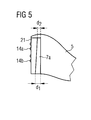
- both the nozzle-side sealing surface 16 and the slide grooves 7a, 7b accordingly Fig. 5
- the grip side T-spring 18 is adjusted accordingly, ie in particular cuboid shaped.
- the T-shaped cut-out in the connecting part 6 correspondingly trapezoidal, so that then a rectangular shaped sealing surface 16 runs in the T-spring 18 at the trapezoidal shaped cutout there and clamps there.
- the clamping of the two components is preferably achieved in that on the one hand the nozzle-side sealing surface 16 is pressed onto the handle-side sealing surface 19 and on the other hand, the surfaces of the right and left sliding 7a, 7b on the right and left Spring clips 17a, 17b support accordingly and the side of the sliding grooves 7a, 7b adjacent surfaces of the nozzle-side T-groove 21 at the spring clips 17a, 17b adjacent surfaces of the handle side T-spring 18 are respectively supported.
- these corresponding surfaces are arranged at an angle of about 4 ° relative to the nozzle-side and handle-side sealing surfaces 16 and 19, so that with increasing insertion depth, the two sealing surfaces 16th , 19 are more and more pressed apart.
- this embodiment of the nozzle 5 can be produced as a disposable item, so that a cumbersome disinfection is eliminated.
- the replacement takes place without any aids by simply inserting the nozzle 5 in the head-side Connecting part 6. Due to the conical or trapezoidal configuration of the nozzle-side T-slot and / or the handle T-spring a reliable press fit can be achieved to a reliable sealing of the connection point between the supply line 9, 10 and the nozzle line 11, 12 to achieve.
Abstract
Description
Die vorliegende Erfindung betrifft ein medizinisches Handstück nach dem Oberbegriff des Patentanspruches 1, sowie eine hierfür geeignete auswechselbare Düse nach dem Oberbegriff des Patentanspruches 8. Insbesondere betrifft die vorliegende Erfindung ein medizinisches Handstück für Dentalzwecke, das eine auswechselbare Düse aufweist, die zum Zuführen medizinisch wirksamer Medien, wie beispielsweise eines Luft-Pulver-Gemischs und/oder eines Fluids, geeignet ist.The present invention relates to a medical handpiece according to the preamble of claim 1, as well as a replaceable nozzle suitable therefor according to the preamble of
Derartige Handstücke, beispielsweise für ein dentales Abrasivstrahlgerät, sind aus der
Aus der
Die
Die
Ein wesentlicher Nachteil der bekannten auswechselbaren Düsen besteht darin, dass diese umständlich sterilisiert werden müssen, bevor sie für die nächste Behandlung verwendet werden können. Darüber hinaus ist der Aufbau und die Art der Verbindung zwischen griffseitiger Zuleitung und Düsenleitung umständlich, da z. B. zusätzliche Anschlussleitungen vorgesehen sind, die zwischen der Griffhülse und der Düse zu liegen kommen und die oft verstopfen oder umständlich zu reinigen sind, weswegen auch diese oftmals ausgewechselt werden müssen.A major disadvantage of the known interchangeable nozzles is that they must be cumbersome sterilized before they can be used for the next treatment. In addition, the structure and the nature of the connection between the handle side supply line and nozzle line is cumbersome because z. B. additional connection lines are provided, which come to rest between the grip sleeve and the nozzle and are often clogged or cumbersome to clean, which is why these often need to be replaced.
Ein weiterer Nachteil der bekannten medizinischen Handstücke besteht darin, dass der Aufbau sowohl der Griffhülse als auch der Düse sehr aufwendig ist, weswegen die Herstellungskosten des medizinischen Handstücks bzw. der auswechselbaren Düse sehr hoch sind, weswegen der behandelnde Arzt in der Regel sowohl die Griffhülse als auch die Düse zur mehrmaligen Verwendung desinfizieren muss. Darüber hinaus besteht bei subgingivalen Anwendungen die Schwierigkeit, dass die Düsendurchmesser zur Vermeidung von Verletzungen nur sehr geringe Werte annehmen dürfen. Dies führt zu langen dünnen Kanälen im Inneren der Düse, die oftmals nicht zufrieden stellend zu reinigen und zu desinfizieren sind.Another disadvantage of the known medical handpieces is that the structure of both the grip sleeve and the nozzle is very expensive, which is why the manufacturing cost of the medical handpiece or the replaceable nozzle are very high, which is why the treating physician usually both the grip sleeve also disinfect the nozzle for repeated use. In addition, in subgingival applications there is the difficulty that nozzle diameters may be very low to avoid injury. This results in long thin channels inside the nozzle, which are often unsatisfactory to clean and disinfect.
Der vorliegenden Erfindung liegt die Aufgabe zugrunde, das medizinische Handstück der vorbekannten Art dahingehend zu verbessern, dass ein umständliches Desinfizieren beschleunigt wird oder entfällt, der Aufbau und die Herstellung des medizinischen Handstücks bzw. der Düse einfacher und günstiger wird und dass die Leerlaufzeiten zwischen zwei Behandlungen eines Patienten kürzer werden, sodass mehr Patienten schneller mit dem medizinischen Handstück behandelt werden können.The present invention has for its object to improve the medical handpiece of the prior art in that a cumbersome disinfection is accelerated or eliminated, the structure and manufacture of the medical handpiece and the nozzle is easier and cheaper and that the idle time between two treatments one Patients are getting shorter so more patients can be treated faster with the medical handpiece.
Die vorliegende Erfindung löst diese Aufgaben durch die kennzeichnenden Merkmale der Patentansprüche 1 und 8. Vorteilhafte Ausgestaltungen der vorliegenden Erfindung sind in den Unteransprüchen gekennzeichnet und dort beschrieben.The present invention solves these objects by the characterizing features of
Das medizinische Handstück der vorliegenden Erfindung weist eine Düse mit mindestens einer Düsenleitung auf, die für die Zuführung des medizinisch wirksamen Mediums dient. An dem Handstück befindet sich, bzw. der vordere Teil des Handstücks ist ein Kopfteil mit einem kopfseitigen Verbindungsteil zum auswechselbaren Verbinden des Handstücks mit der Düse, wobei das Handstück mindestens eine Zuleitung aufweist, mit dessen Hilfe das medizinisch wirksame Medium zugeführt wird. Die mindestens eine Zuleitung wird mit der mindestens einen Düsenleitung durch eine dichtende Presspassung einer düsenseitigen Dichtfläche und einer griffseitigen Dichtfläche verbunden.The medical handpiece of the present invention has a nozzle with at least one nozzle line, which serves for the supply of medically active medium. On the handpiece is located, or the front part of the handpiece is a head part with a head-side connecting part for interchangeable connection of the handpiece with the nozzle, wherein the handpiece has at least one supply line, by means of which the medically active medium is supplied. The at least one supply line is connected to the at least one nozzle line by a sealing press fit of a nozzle-side sealing surface and a grip-side sealing surface.
Der Vorteil der vorliegenden Erfindung liegt darin, dass keine Verbindungsleitungen oder andere Verbindungsteile notwendig sind, um die Düsenleitung der Düse mit der Zuleitung des Griffteils zu verbinden. Der wesentliche Vorteil einer solchen Anordnung besteht darin, dass die Düse sehr klein und kostengünstig hergestellt werden kann, so dass diese als Einmalartikel zur Anwendung kommt und nicht mehr desinfiziert werden muss. Um diese besonders klein und kostengünstig ausführen zu können, muss die dichtende Presspassung durch möglichst einfache Mittel erzielt werden. Dies hat im Übrigen den Vorteil, dass die verhältnismäßig kleinen und dünnen Kanäle im Inneren der Düse nicht mehr gereinigt bzw. desinfiziert werden müssen, weil die Düse selbst nach jeder Anwendung entsorgt wird und bei jeder Anwendung eine neue Düse zum Einsatz kommt.The advantage of the present invention is that no connecting lines or other connecting parts are necessary to connect the nozzle line of the nozzle with the supply of the handle part. The main advantage of such an arrangement is that the nozzle can be made very small and inexpensive, so that it is used as a disposable article and no longer needs to be disinfected. In order to carry out this particularly small and inexpensive, the sealing press fit must be achieved by the simplest possible means. This has the advantage that the relatively small and thin channels inside the nozzle no longer need to be cleaned or disinfected, because the nozzle itself is disposed of after each use and a new nozzle is used with each application.
Nach einer bevorzugten Ausführungsform der vorliegenden Erfindung ist die griffseitige Dichtfläche am Ende einer griffseitigen T-Feder des Kopfteils angeordnet, in die eine düsenseitige T-Nut einführbar ist, die die düsenseitige Dichtfläche trägt. Mit Vorteil ist die Einführachse zum Einführen der T-Nut in die T-Feder in etwa senkrecht zur Längsachse des Handstücks, wobei Einführwinkel von vorteilhafterweise 45° - 135°, besonders bevorzugt 80° - 100° in Frage kommen.According to a preferred embodiment of the present invention, the handle-side sealing surface is arranged at the end of a handle-side T-spring of the head part, into which a nozzle-side T-groove is inserted, which carries the nozzle-side sealing surface. Advantageously, the insertion axis for inserting the T-slot in the T-spring is approximately perpendicular to the longitudinal axis of the handpiece, wherein insertion angle of advantageously 45 ° - 135 °, particularly preferably 80 ° - 100 ° come into question.
Die düsenseitige Dichtfläche weist mit Vorteil mindestens eine Leitungsdichtung auf, die mindestens eine Leitungsöffnung abdichtet, in die die mindestens eine Düsenleitung mündet. Diese Leitungsdichtung kann kreisförmig um die Leitungsöffnung der Düsenleitung herum angeordnet sein und aus demselben Material wie die Düse selbst bestehen. Nach einer anderen Ausführungsform weist die griffseitige Dichtfläche an den Leitungsöffnungen der Zuleitungen Leitungsdichtungen auf, die dann eine dichtende Presspassung der düsenseitigen Dichtfläche und der griffseitigen Dichtfläche dergestalt ermöglichen, dass die sich gegenüberliegenden Leitungsöffnungen von Zuleitung und Düsenleitung nach außen hin abgedichtet werden.The nozzle-side sealing surface advantageously has at least one line seal which seals at least one line opening into which the at least one nozzle line opens. This line seal can be arranged in a circle around the line opening of the nozzle line and consist of the same material as the nozzle itself. According to another embodiment, the handle-side sealing surface at the conduit openings of the leads on line seals, which then allow a sealing interference fit of the nozzle-side sealing surface and the handle-side sealing surface such that the opposite conduit openings of supply and nozzle line are sealed to the outside.
Die düsenseitige T-Nut weist mit Vorteil eine rechte Gleitnut und eine linke Gleitnut auf, in die eine rechte Federklammer und eine linke Federklammer der griffseitigen T-Feder eingreifen, sodass eine dichtende Presspassung zwischen der düsenseitigen Dichtfläche und der griffseitigen Dichtfläche bewirkt werden kann. Die dichtende Presspassung der düsenseitigen Dichtfläche und der griffseitigen Dichtfläche ist bereits dann erzielt, wenn die sich gegenüberstehenden Leitungen dichtend miteinander verbunden sind. Um diese Presspassung zu erzielen, sind grundsätzlich zwei bevorzugte Ausführungsformen vorgesehen:
- 1. Die düsenseitige Dichtfläche wird in der Aufsicht trapezförmig geformt, so dass die seitlichen Längskanten der düsenseitigen Dichtflächen mit den seitlichen Längskanten der griffseitigen T-Feder derart zusammenwirken, dass beim Einführen der Düse in das kopfseitige Verbindungsteil die Presspassung bewirkt wird. Dies kann beispielsweise dadurch erzielt werden, dass die untere Querkante der trapezförmigen, düsenseitigen Dichtfläche kleiner und die obere Querkante der trapezförmigen, düsenseitigen Dichtfläche größer ist als die obere Öffnung der griffseitigen T-Feder, so dass die seitlichen, konisch zulaufenden Längskanten beim Einführen der Düse in das kopfseitige Verbindungsteil in der griffseitigen T-Feder keilförmig auflaufen und dort klemmen. Gleichzeitig wird durch die trapezförmige Ausführung das Einführen der Düse in das kopfseitige Verbindungsteil erleichtert.
- 2. Eine untere Gleitnutbreite wird größer als eine obere Gleitnutbreite der düsenseitigen T-Nut ausgebildet, so dass die untere Stärke der düsenseitigen Dichtfläche geringer ist als die obere Stärke der düsenseitigen Dichtfläche, wobei die untere Stärke der düsenseitigen Dichtfläche kleiner ist als die T-Federbreite der griffseitigen T-Feder, die obere Stärke der düsenseitigen Dichtfläche aber größer ist als die T-Federbreite, so dass auch hier beim Einführen der Düse in das kopfseitige Verbindungsteil durch den konischen Zuschnitt der Gleitnut ein keilförmiges Auflaufen der seitlichen Längskanten der düsenseitigen Dichtfläche innerhalb der T-Feder und somit eine Klemmung bewirkt wird.
- 1. The nozzle-side sealing surface is shaped trapezoidal in plan view, so that the lateral longitudinal edges of the nozzle-side sealing surfaces with the lateral longitudinal edges of the handle side T-spring cooperate such that upon insertion of the nozzle in the head-side connecting part, the interference fit is effected. This can be achieved, for example, that the lower transverse edge of the trapezoidal, nozzle-side sealing surface is smaller and the upper transverse edge of the trapezoidal, nozzle-side sealing surface is greater than the upper opening of the handle T-spring, so that the lateral, tapered longitudinal edges during insertion of the nozzle in the head-side connecting part in the grip side T-spring run up in a wedge shape and clamp there. At the same time, the insertion of the nozzle into the head-side connecting part is facilitated by the trapezoidal design.
- 2. A lower sliding groove width is made larger than an upper Gleitnutbreite the nozzle-side T-groove, so that the lower thickness of the nozzle-side sealing surface is less than the upper thickness of the nozzle-side sealing surface, wherein the lower thickness of the nozzle-side sealing surface is smaller than the T-spring width the grip side T-spring, the upper thickness of the nozzle-side sealing surface but is greater than the T-spring width, so that here again when inserting the nozzle in the head-side connecting part by the conical cut of the sliding groove wedge-shaped emergence of the lateral longitudinal edges the nozzle-side sealing surface within the T-spring and thus a clamping is effected.
Nach einer weiteren bevorzugten Ausführungsform der vorliegenden Erfindung kann die Düse aber auch durch einen Bajonett-, Dreh- oder einen Schraubverschluss am Verbindungsteil angebracht werden, sodass es zu einer dichtenden Presspassung der düsenseitigen Dichtfläche und der griffseitigen Dichtfläche kommt, wobei im Falle von Leitungsdichtungen diese Dichtflächen durch die Oberflächen der Leitungsdichtungen selbst repräsentiert werden. Auch hier stehen die Ebenen der Dichtflächen im Wesentlichen senkrecht auf der Längsachse des Handstücks.According to a further preferred embodiment of the present invention, however, the nozzle can also be attached by a bayonet, twist or a screw on the connecting part, so that there is a sealing interference fit of the nozzle-side sealing surface and the handle-side sealing surface, wherein in the case of line seals these sealing surfaces are represented by the surfaces of the line seals themselves. Again, the planes of the sealing surfaces are substantially perpendicular to the longitudinal axis of the handpiece.
Die vorliegende Erfindung betrifft darüber hinaus eine Düse für ein medizinisches Handstück, wobei die Düse eine düsenseitige Dichtfläche aufweist, die mit einer griffseitigen Dichtfläche derart dichtend verbindbar ist, dass mindestens eine Leitungsöffnung von mindestens einer Düsenleitung mit mindestens einer Zuleitung des Handstücks verbindbar ist. Eine erste Düsenleitung mündet mit einer zweiten Düsenleitung an der erfindungsgemäßen Düsenspitze derart, dass zwei medizinisch wirksame Medien gleichzeitig, ggf. getrennt, an der Düsenspitze austreten.The present invention further relates to a nozzle for a medical handpiece, wherein the nozzle has a nozzle-side sealing surface which is sealingly connectable with a grip-side sealing surface, that at least one conduit opening of at least one nozzle line with at least one supply line of the handpiece is connectable. A first nozzle line opens with a second nozzle line to the nozzle tip according to the invention such that two medically effective media emerge at the same time, if necessary separately, at the nozzle tip.
Mit Vorteil besteht die Düse aus einem elastisch verformbaren Kunststoffmaterial, insbesondere aus einem Elastomer, so dass beim Einführen der Düse in das kopfseitige Verbindungsteil eine Verformung des Kunststoffmaterials möglich ist, um somit eine dichtende Presspassung zu erzielen. Mit Vorteil sind die Leitungsdichtungen dabei aus demselben Material wie die Düse geformt, ggf. einstückig mit dieser, die beispielsweise durch ein Spritzgussverfahren als Einmalartikel ausgebildet sein kann.Advantageously, the nozzle consists of an elastically deformable plastic material, in particular of an elastomer, so that when inserting the nozzle in the head-side connecting part, a deformation of the plastic material is possible, thus achieving a sealing interference fit. Advantageously, the line seals are formed from the same material as the nozzle, possibly in one piece with this, for example, by an injection molding process can be designed as a disposable item.
Eine besonders bevorzugte Ausführungsform der vorliegenden Erfindung wird durch die beiliegenden Zeichnungen näher erläutert. Dabei zeigen:
- Fig. 1
- einen schematischen Querschnitt durch ein erfindungsgemäßes Handstück mit Düse,
- Fig. 2
- eine schematische Seitenansicht auf ein Handstück mit Schlauch und Düse,
- Fig. 3
- eine schematische Queransicht der erfindungsgemäßen Düse,
- Fig. 4
- eine schematische Queransicht des kopfseitigen Verbindungsteils mit Kopfteil des erfindungsgemäßen Handstücks, und
- Fig. 5
- eine teilweise Queransicht des griffseitigen Teils der erfindungsgemäßen Düse.
- Fig. 1
- a schematic cross section through an inventive handpiece with nozzle,
- Fig. 2
- a schematic side view of a handpiece with hose and nozzle,
- Fig. 3
- a schematic cross-sectional view of the nozzle according to the invention,
- Fig. 4
- a schematic cross-sectional view of the head-side connecting part with the head part of the handpiece according to the invention, and
- Fig. 5
- a partial transverse view of the handle-side part of the nozzle according to the invention.
Das Handstück 1 weist eine erste Zuleitung 9 zum Zuführen beispielsweise eines Luft-Pulver-Gemisches und eine zweite Zuleitung 10 zum Zuführen beispielsweise von Wasser auf. Die Düse 5, die in der Regel in direktem Kontakt mit dem zu behandelnden Patienten steht, soll auswechselbar angeordnet sein, weswegen diese eine düsenseitige T-Nut 21 aufweist, die in eine griffseitige T-Feder 18 einführbar ist (vgl.
Gespeist wird die erste Düsenleitung 11 über eine erste Leitungsöffnung 13a, während die zweite Düsenleitung 12 über eine zweite Leitungsöffnung 13b gespeist wird. Um die Leitungsöffnungen 13a, 13b herum sind Leitungsdichtungen 14a, 14b angedeutet. Diese Leitungsdichtungen 14a, 14b können beliebige Formen annehmen, solange gewährleistet ist, dass sowohl eine Dichtung nach außen als auch eine Dichtung zwischen den Leitungsöffnungen 13a, 13b sichergestellt ist. Beispielsweise könnten die Leitungsdichtungen 14a, 14b auch am Rande der Dichtfläche 16 angeordnet sein, wobei eine Querdichtungsnut dann zwischen den beiden Leitungsöffnungen 13a, 13b vorgesehen sein muss. Mit Vorteil sind die Leitungsdichtungen 14a, 14b einstückig aus demselben Material wie die Düse 5 gefertigt, um die Kosten der Düse 5 möglichst niedrig zu halten.The
Die Düse 5 weist eine düsenseitige T-Nut 21 auf, die dadurch gebildet wird, dass eine rechte Gleitnut 7a und eine linke Gleitnut 7b von der Dichtfläche 16 beabstandet, seitlich in die Oberfläche der Düse 5 eingekerbt sind. Mit Vorteil verlaufen die Gleitnuten 7a, 7b nicht vollständig über die gesamte Oberfläche der Düse 5, sondern enden kurz unterhalb der oberen Ausdehnung der Düse 5, so dass ein Nutabsatz 15 entsteht. Dieser Nutabsatz 15 verhindert beim Einführen in das kopfseitige Verbindungsteil 6 (vgl.
- Einerseits kann die düsenseitige Dichtfläche 16 in der Aufsicht trapezförmig geformt sein (vgl.
Fig. 3 ), so dass die seitlichen Längskanten der düsenseitigen Dichtflächen 16 mit den seitlichen Längskanten der griffseitigen T-Feder 18 derart zusammenwirken, dass beim Einführen der Düse 5 indas kopfseitige Verbindungsteil 6 die Presspassung bewirkt wird. Zu diesem Zweck ist die untere Querseite der trapezförmigen Dichtfläche 16 kleiner als die obere Breite der T-förmigenAusfräsung am Verbindungsteil 6, während die obere Querseite der trapezförmigen Dichtfläche 16 im Bereich des Nutabsatzes 15 größer ist, als die obere Breite der T-förmigen Ausfräsung desVerbindungsteils 6, so dass beim Einführen der Düse 5 eine Klemmung bewirkt wird.
- On the one hand, the nozzle-
side sealing surface 16 may be formed trapezoidal in plan view (see.Fig. 3 ), so that the lateral longitudinal edges of the nozzle-side sealing surfaces 16 cooperate with the lateral longitudinal edges of the handle side T-spring 18 such that when inserting thenozzle 5 in the head-side connecting part 6, the interference fit is effected. For this purpose, the lower transverse side of thetrapezoidal sealing surface 16 is smaller than the upper width of the T-shaped cutout on the connectingpart 6, while the upper transverse side of thetrapezoidal sealing surface 16 in the region of theNutabsatzes 15 is greater than the upper width of the T-shaped cutout the connectingpart 6, so that when inserting thenozzle 5, a clamping is effected.
Andererseits ist es gemäß einer schematischen Ansicht des rückwärtigen Teils der Düse 5 in
Natürlich ist es auch möglich, sowohl die düsenseitige Dichtfläche 16 als auch die Gleitnuten 7a, 7b entsprechend
Nach einer bevorzugten Ausführungsform der vorliegenden Erfindung wird die Klemmung der beiden Bauteil bevorzugt dadurch erreicht, dass zum Einen die düsenseitige Dichtfläche 16 auf die griffseitige Dichtfläche 19 gedrückt wird und zum Anderen sich die Flächen der rechten und linken Gleitnut 7a, 7b an den rechten und linken Federklammern 17a, 17b entsprechend abstützen und sich die seitlichen den Gleitnuten 7a, 7b benachbarten Flächen der düsenseitigen T-Nut 21 an den der Federklammern 17a, 17b benachbarten Flächen der griffseitigen T-Feder 18 jeweils abstützen. Um dies zu erreichen, sind diese entsprechenden Flächen (21/7a,b und 18/17a,b) in einem Winkel von etwa 4° gegenüber den düsenseitigen und griffseitigen Dichtflächen 16 bzw. 19 angeordnet, so dass mit zunehmender Einschubtiefe die beiden Dichtflächen 16, 19 mehr und mehr auseinandergedrückt werden.According to a preferred embodiment of the present invention, the clamping of the two components is preferably achieved in that on the one hand the nozzle-
Durch diese Ausgestaltung der Düse 5 kann diese als Einmalartikel hergestellt werden, sodass ein umständliches Desinfizieren entfällt. Das Auswechseln erfolgt dabei ohne jegliche Hilfsmittel durch einfaches Einführen der Düse 5 in das kopfseitige Verbindungsteil 6. Durch die konische, bzw. trapezförmige Ausgestaltung der düsenseitigen T-Nut und/oder der griffseitigen T-Feder kann eine zuverlässige Presspassung erzielt werden, um eine zuverlässige Abdichtung der Verbindungsstelle zwischen der Zuleitung 9, 10 und der Düsenleitung 11, 12 zu erzielen.As a result of this embodiment of the
Claims (13)
dadurch gekennzeichnet, dass
die mindestens eine Zuleitung (9, 10) mit der mindestens einen Düsenleitung (11, 12) durch eine dichtende Presspassung einer düsenseitigen Dichtfläche (16) und einer griffseitigen Dichtfläche (19) verbindbar ist.Medical handpiece (1) having a nozzle (5) with at least one nozzle line (11, 12) for the delivery of a medically active medium, a head part (4) with a head-side connecting part (6) for interchangeable connection of the handpiece (1) with the Nozzle (5) and with at least one supply line (9, 10),
characterized in that
the at least one feed line (9, 10) can be connected to the at least one nozzle line (11, 12) by a sealing press fit of a nozzle-side sealing surface (16) and a grip-side sealing surface (19).
dadurch gekennzeichnet, dass
die griffseitige Dichtfläche (19) am Ende einer griffseitigen T-Feder (18) des Kopfteils (6) angeordnet ist, in die eine düsenseitige T-Nut (21) einführbar ist, die die düsenseitige Dichtfläche (16) trägt.Medical handpiece according to claim 1,
characterized in that
the handle-side sealing surface (19) at the end of a handle side T-spring (18) of the head part (6) is arranged, in which a nozzle-side T-groove (21) can be inserted, which carries the nozzle-side sealing surface (16).
dadurch gekennzeichnet, dass
die düsenseitige Dichtfläche (16) mindestens eine Leitungsdichtung (14a, 14b) aufweist, die mindestens eine Leitungsöffnung (13a, 13b) abdichtet, in die die mindestens eine Düsenleitung (11, 12) mündet.Medical handpiece according to one of claims 1 or 2,
characterized in that
the nozzle-side sealing surface (16) has at least one line seal (14a, 14b) which seals at least one line opening (13a, 13b) into which the at least one nozzle line (11, 12) opens.
dadurch gekennzeichnet, dass
die düsenseitige T-Nut (21) eine rechte Gleitnut (7a) und eine linke Gleitnut (7b) bildet, in die eine rechte Federklammer (17a) und eine linke Federklammer (17b) der griffseitigen T-Feder (18) eingreifen, so dass eine dichtende Presspassung zwischen der düsenseitigen Dichtfläche (16) und der griffseitigen Dichtfläche (19) bewirkt wird.Medical handpiece according to one of the preceding claims,
characterized in that
the nozzle-side T-groove (21) forms a right sliding groove (7a) and a left sliding groove (7b) into which a right spring clip (17a) and a left spring clip (17b) of the grip side T-spring (18) engage, so that a sealing interference fit between the nozzle-side sealing surface (16) and the handle-side sealing surface (19) is effected.
dadurch gekennzeichnet, dass
die düsenseitige Dichtfläche (16) in der Aufsicht trapezförmig geformt ist, so dass die seitlichen Längskanten der düsenseitigen Dichtflächen (16) mit den seitlichen Längskanten der griffseitigen T-Feder (18) derart zusammenwirken, dass beim Einführen der Düse (5) in das kopfseitige Verbindungsteil (6) die Presspassung bewirkt wird.Medical handpiece according to claim 4,
characterized in that
the nozzle-side sealing surface (16) is formed trapezoidal in plan view, so that the lateral longitudinal edges of the nozzle-side sealing surfaces (16) with the lateral longitudinal edges of the handle side T-spring (18) cooperate such that upon insertion of the nozzle (5) in the head-side Connecting part (6) the press fit is effected.
dadurch gekennzeichnet, dass
eine untere Gleitnutbreite (d1) größer ist als eine obere Gleitnutbreite (d2) der düsenseitigen T-Nut (21), so dass die untere Stärke der düsenseitigen Dichtfläche (16) geringer ist als die obere Stärke der düsenseitigen Dichtfläche (16), wobei die untere Stärke der düsenseitigen Dichtfläche (16) kleiner ist als die T-Federbreite (a) der griffseitigen T-Feder (18), die obere Stärke der düsenseitigen Dichtfläche (16) aber größer ist als die T-Federbreite (a).Medical handpiece according to one of the preceding claims,
characterized in that
a lower Gleitnutbreite (d 1 ) is greater than an upper Gleitnutbreite (d 2 ) of the nozzle-side T-groove (21), so that the lower thickness of the nozzle-side sealing surface (16) is less than the upper thickness of the nozzle-side sealing surface (16), wherein the lower thickness of the nozzle-side sealing surface (16) is smaller than the T-spring width (a) of the handle side T-spring (18), the upper thickness of the nozzle-side sealing surface (16) but greater than the T-spring width (a).
dadurch gekennzeichnet, dass
die Düse (5) eine erste Düsenleitung (11) zum Zuführen eines Pulver-Luftgemisches und eine zweite Düsenleitung (12) zum Zuführen eines Fluids aufweist, dass das Kopfteil (4) eine erste Zuleitung (9) und eine zweite Zuleitung (10) zur Zuführung des Luft-Pulver-Gemischs sowie des Fluids aufweist und dass die düsenseitige Dichtfläche (16) eine erste Leitungsöffnung (13a) für die erste Düsenleitung (11) und eine zweite Leitungsöffnung (13b) für eine zweite Düsenleitung (12) aufweist, die jeweils durch eine erste Leitungsdichtung (14a) und ein zweite Leitungsdichtung (14b) umgeben sind, die beim Einführen der Düse (5) in die griffseitige T-Feder (18) eine dichtende Presspassung gegenüber den Öffnungen der ersten und zweiten Zuleitung (9, 10) herstellen.Medical handpiece according to one of the preceding claims,
characterized in that
the nozzle (5) has a first nozzle line (11) for supplying a powder-air mixture and a second nozzle line (12) for supplying a fluid, that the head part (4) has a first supply line (9) and a second supply line (10) Having supply of the air-powder mixture and the fluid and that the nozzle-side sealing surface (16) has a first conduit opening (13a) for the first nozzle line (11) and a second conduit opening (13b) for a second nozzle line (12), respectively surrounded by a first line seal (14a) and a second line seal (14b) which, upon insertion of the nozzle (5) into the handle side T-spring (18), provide a sealing interference fit with the openings of the first and second feed lines (9, 10). produce.
dadurch gekennzeichnet, dass
die Düse (5) eine düsenseitige Dichtfläche (16) aufweist, die mit einer griffseitigen Dichtfläche (19) derart dichtend verbindbar ist, dass mindestens eine Leitungsöffnung (13a, 13b) von mindestens einer Düsenleitung (11, 12) mit mindestens einer Zuleitung (9, 10) des Handstücks (1) dichtend verbindbar ist.A nozzle (5) for a medical handpiece (1) according to one of the preceding claims,
characterized in that
the nozzle (5) has a nozzle-side sealing surface (16), which is so sealingly connectable with a grip-side sealing surface (19) that at least one conduit opening (13a, 13b) of at least one nozzle line (11, 12) with at least one supply line (9, 10) of the handpiece (1) is sealingly connectable.
dadurch gekennzeichnet, dass
eine erste Düsenleitung (11) mit einer zweiten Düsenleitung (12) an einer Düsenspitze (8) derart münden, dass zwei medizinisch wirksame Medien gleichzeitig an der Düsenspitze (8) austreten.Nozzle (5) according to claim 8,
characterized in that
a first nozzle line (11) with a second nozzle line (12) to a nozzle tip (8) open so that two medically effective media simultaneously emerge at the nozzle tip (8).
dadurch gekennzeichnet, dass
die Düse aus einem elastisch verformbaren Kunststoffmaterial, insbesondere aus einem Elastomer, besteht.Nozzle (5) according to claim 8 or 9,
characterized in that
the nozzle consists of an elastically deformable plastic material, in particular of an elastomer.
dadurch gekennzeichnet, dass
die Düse einteilig ist.A nozzle (5) according to any one of claims 8 to 10,
characterized in that
the nozzle is in one piece.
dadurch gekennzeichnet, dass
die Leitungsdichtungen (14a, 14b) aus demselben Material wie die Düse (5) bestehen.Nozzle (5) according to one of claims 8-11,
characterized in that
the line seals (14a, 14b) are made of the same material as the nozzle (5).
dadurch gekennzeichnet, dass
die Düse (5) durch ein Spritzgussverfahren herstellbar und als Einmalartikel ausgebildet ist.A nozzle (5) according to any one of claims 8-12,
characterized in that
the nozzle (5) can be produced by an injection molding process and designed as a disposable article.
Applications Claiming Priority (1)
| Application Number | Priority Date | Filing Date | Title |
|---|---|---|---|
| DE102006060076A DE102006060076B3 (en) | 2006-12-19 | 2006-12-19 | Medicinal handpiece for dental abrasive stream device, has nozzle with nozzle pipe for supplying medically active medium, and supply lines connected with pipe through tight press fitting of nozzle-sided and handle-sided sealing surfaces |
Publications (2)
| Publication Number | Publication Date |
|---|---|
| EP1935367A1 true EP1935367A1 (en) | 2008-06-25 |
| EP1935367B1 EP1935367B1 (en) | 2010-05-12 |
Family
ID=39105471
Family Applications (1)
| Application Number | Title | Priority Date | Filing Date |
|---|---|---|---|
| EP07021725A Active EP1935367B1 (en) | 2006-12-19 | 2007-11-08 | Medical tool holder and replaceable nozzle for such |
Country Status (8)
| Country | Link |
|---|---|
| US (1) | US7762812B2 (en) |
| EP (1) | EP1935367B1 (en) |
| JP (1) | JP5171233B2 (en) |
| CN (1) | CN101204599B (en) |
| AT (1) | ATE467396T1 (en) |
| CA (1) | CA2615170C (en) |
| DE (3) | DE102006060076B3 (en) |
| ES (1) | ES2341492T3 (en) |
Families Citing this family (13)
| Publication number | Priority date | Publication date | Assignee | Title |
|---|---|---|---|---|
| WO2011077291A1 (en) * | 2009-12-23 | 2011-06-30 | Koninklijke Philips Electronics N.V. | A guidance assembly tip for a liquid droplet spray teeth cleaning appliance |
| DE102010051227A1 (en) * | 2010-11-12 | 2012-05-16 | Dental Care Innovation Gmbh | Nozzle for the emission of liquid cleaning agents with abrasive particles dispersed therein |
| EP2742897A1 (en) | 2012-12-17 | 2014-06-18 | 3M Innovative Properties Company | Nozzle head, hand piece and powder jet device for applying a dental material |
| US9662180B2 (en) | 2012-12-17 | 2017-05-30 | 3M Innovative Properties Company | Device for dispensing a dental material with locking mechanism |
| EP2742898A1 (en) | 2012-12-17 | 2014-06-18 | 3M Innovative Properties Company | Powder jet device for dispensing a dental material |
| US10433931B2 (en) | 2013-03-07 | 2019-10-08 | Nakanishi Inc. | Dental handpiece nozzle |
| CN108703809A (en) * | 2013-03-07 | 2018-10-26 | 株式会社中西 | Dental handpiece with nozzle connection structure |
| DE102016124212B4 (en) * | 2016-12-13 | 2022-05-12 | Ferton Holding S.A. | mixing chamber and handpiece |
| USD825741S1 (en) | 2016-12-15 | 2018-08-14 | Water Pik, Inc. | Oral irrigator handle |
| CN109124796B (en) * | 2018-09-28 | 2020-12-29 | 先临三维科技股份有限公司 | Injection molding device and tooth mold forming method thereof |
| US11052205B2 (en) * | 2019-06-11 | 2021-07-06 | Neosinus Health Inc | Devices and methods for delivering fluid to a nasal cavity |
| CN211325726U (en) * | 2019-11-13 | 2020-08-25 | 桂林市啄木鸟医疗器械有限公司 | Rotatable subgingival spray nozzle of dental sand blasting machine |
| WO2024028344A1 (en) * | 2022-08-03 | 2024-02-08 | GalvoSurge Dental AG | Application nozzle for discharging a dental active substance in the oral cavity of a patient, and active substance applicator having such an application nozzle |
Citations (3)
| Publication number | Priority date | Publication date | Assignee | Title |
|---|---|---|---|---|
| US4519385A (en) | 1982-12-01 | 1985-05-28 | Snyder Laboratories, Inc. | Lavage handpiece |
| EP0299229A1 (en) | 1987-07-13 | 1989-01-18 | Dentsply International | Spray shield |
| US5242300A (en) * | 1992-12-23 | 1993-09-07 | Esrock Bernard S | Nozzle for dental tool |
Family Cites Families (10)
| Publication number | Priority date | Publication date | Assignee | Title |
|---|---|---|---|---|
| GR920100104A (en) * | 1992-03-13 | 1993-11-30 | Christodoulos I Stefanadis | Temporary luminal stent for the support of the vascular wall. |
| DE19714276C2 (en) * | 1997-04-07 | 2001-04-19 | Ferton Holding Sa | Dental handpiece |
| JP4159202B2 (en) * | 1998-12-21 | 2008-10-01 | 日本特殊陶業株式会社 | Calcium phosphate cement kneading apparatus and method for preparing calcium phosphate cement kneaded material |
| DE10114324B4 (en) * | 2001-03-23 | 2005-03-10 | Ferton Holding Sa | Nozzle piece for a dantal abrasive blasting unit |
| DE10212925B4 (en) | 2002-03-22 | 2004-07-08 | Ferton Holding S.A. | Handpiece for a dental abrasive blasting device |
| US6783037B1 (en) * | 2003-04-10 | 2004-08-31 | John E. Bonham | Locking aerosol spray tube |
| DE10331583B3 (en) | 2003-07-11 | 2004-07-15 | Ferton Holding S.A. | Nozzle piece for a dental powder stream device has several nozzle openings formed in the casing surface of the front end of a tubular partial length of the nozzle piece |
| US7530808B2 (en) * | 2004-03-10 | 2009-05-12 | Cao Group, Inc | Binary dental bleaching using switch-closable double barrel syringe |
| CN2715857Y (en) * | 2004-07-20 | 2005-08-10 | 刘军伍 | Dot killing type aerosol spray cap |
| US7179085B2 (en) | 2004-11-16 | 2007-02-20 | Denteque | Apparatus for dispensing dental solutions |
-
2006
- 2006-12-19 DE DE102006060076A patent/DE102006060076B3/en active Active
-
2007
- 2007-11-08 ES ES07021725T patent/ES2341492T3/en active Active
- 2007-11-08 EP EP07021725A patent/EP1935367B1/en active Active
- 2007-11-08 AT AT07021725T patent/ATE467396T1/en active
- 2007-11-08 DE DE502007003719T patent/DE502007003719D1/en active Active
- 2007-11-08 DE DE202007019027U patent/DE202007019027U1/en not_active Expired - Lifetime
- 2007-12-12 JP JP2007320691A patent/JP5171233B2/en active Active
- 2007-12-14 US US11/956,596 patent/US7762812B2/en active Active
- 2007-12-17 CN CN200710199351XA patent/CN101204599B/en active Active
- 2007-12-17 CA CA2615170A patent/CA2615170C/en active Active
Patent Citations (3)
| Publication number | Priority date | Publication date | Assignee | Title |
|---|---|---|---|---|
| US4519385A (en) | 1982-12-01 | 1985-05-28 | Snyder Laboratories, Inc. | Lavage handpiece |
| EP0299229A1 (en) | 1987-07-13 | 1989-01-18 | Dentsply International | Spray shield |
| US5242300A (en) * | 1992-12-23 | 1993-09-07 | Esrock Bernard S | Nozzle for dental tool |
Also Published As
| Publication number | Publication date |
|---|---|
| CN101204599A (en) | 2008-06-25 |
| CA2615170A1 (en) | 2008-06-19 |
| EP1935367B1 (en) | 2010-05-12 |
| CA2615170C (en) | 2016-11-15 |
| JP2008149138A (en) | 2008-07-03 |
| JP5171233B2 (en) | 2013-03-27 |
| CN101204599B (en) | 2011-11-02 |
| US7762812B2 (en) | 2010-07-27 |
| DE502007003719D1 (en) | 2010-06-24 |
| DE202007019027U1 (en) | 2010-04-01 |
| DE102006060076B3 (en) | 2008-03-27 |
| US20080145814A1 (en) | 2008-06-19 |
| ATE467396T1 (en) | 2010-05-15 |
| ES2341492T3 (en) | 2010-06-21 |
Similar Documents
| Publication | Publication Date | Title |
|---|---|---|
| EP1935367B1 (en) | Medical tool holder and replaceable nozzle for such | |
| EP1250106B1 (en) | Rinsing cannula for rinsing a root canal of a tooth | |
| DE10239870A1 (en) | Dental interior Files | |
| DE3412667A1 (en) | DEVICE FOR CLEANING CHANNELS IN AN ENDOSCOPE | |
| DE3044025C2 (en) | Handpiece for a mouth rinsing device | |
| DE102005044841A1 (en) | Suction device for removal of surplus of dental impression material, comprising adjusting device for suction forces | |
| DE3232329C2 (en) | ||
| EP3210566A1 (en) | Denture cleaning apparatus | |
| EP1420710A2 (en) | Medical or dental handpiece with a rear and a front shaft section that form an obtuse angle | |
| EP2995274B1 (en) | Handheld dental instrument and head housing for the same | |
| DE4029369C2 (en) | ||
| EP1514575B1 (en) | Device for cleaning Luer-Lock connectors | |
| EP2548524B1 (en) | Clipper | |
| EP2124812A1 (en) | Medical handle piece in particular for dental medicine with two separate outlet openings for media | |
| DE2829271C2 (en) | Device for applying a sterile cooling and rinsing liquid to a wound surface | |
| DE10235136B4 (en) | Interdental device for cleaning interdental spaces | |
| DE3216017C2 (en) | Device for supplying an osteotomy area with sterile cooling liquid | |
| EP0031126A1 (en) | Filtration device for the bacterial sterilisation of a coolant in jaw surgery appliances | |
| CH657520A5 (en) | Dental instrument | |
| DE102015000002B4 (en) | Holder for medical devices in a cleaning apparatus | |
| EP3917441A1 (en) | Holding device for surgical handpieces | |
| DE1281630B (en) | Device for root canal treatment of teeth | |
| WO2023046708A1 (en) | Dental cannula for dental syringe for discharging media | |
| AT405902B (en) | HANDPIECE DEVICE FOR A MEDICAL OR DENTAL MEDICAL TREATMENT PLACE OR FOR A TECHNICAL TREATMENT PLACE IN A MEDICAL OR DENTAL MEDICAL LABORATORY | |
| DE102020117381A1 (en) | Surgical handpiece with connection points that cannot be confused |
Legal Events
| Date | Code | Title | Description |
|---|---|---|---|
| PUAI | Public reference made under article 153(3) epc to a published international application that has entered the european phase |
Free format text: ORIGINAL CODE: 0009012 |
|
| AK | Designated contracting states |
Kind code of ref document: A1 Designated state(s): AT BE BG CH CY CZ DE DK EE ES FI FR GB GR HU IE IS IT LI LT LU LV MC MT NL PL PT RO SE SI SK TR |
|
| AX | Request for extension of the european patent |
Extension state: AL BA HR MK RS |
|
| 17P | Request for examination filed |
Effective date: 20080715 |
|
| 17Q | First examination report despatched |
Effective date: 20080818 |
|
| AKX | Designation fees paid |
Designated state(s): AT BE BG CH CY CZ DE DK EE ES FI FR GB GR HU IE IS IT LI LT LU LV MC MT NL PL PT RO SE SI SK TR |
|
| GRAP | Despatch of communication of intention to grant a patent |
Free format text: ORIGINAL CODE: EPIDOSNIGR1 |
|
| GRAS | Grant fee paid |
Free format text: ORIGINAL CODE: EPIDOSNIGR3 |
|
| GRAA | (expected) grant |
Free format text: ORIGINAL CODE: 0009210 |
|
| AK | Designated contracting states |
Kind code of ref document: B1 Designated state(s): AT BE BG CH CY CZ DE DK EE ES FI FR GB GR HU IE IS IT LI LT LU LV MC MT NL PL PT RO SE SI SK TR |
|
| REG | Reference to a national code |
Ref country code: GB Ref legal event code: FG4D Free format text: NOT ENGLISH |
|
| REG | Reference to a national code |
Ref country code: CH Ref legal event code: NV Representative=s name: LUCHS & PARTNER PATENTANWAELTE Ref country code: CH Ref legal event code: EP |
|
| REG | Reference to a national code |
Ref country code: NL Ref legal event code: T3 |
|
| REG | Reference to a national code |
Ref country code: ES Ref legal event code: FG2A Ref document number: 2341492 Country of ref document: ES Kind code of ref document: T3 |
|
| REG | Reference to a national code |
Ref country code: IE Ref legal event code: FG4D Free format text: LANGUAGE OF EP DOCUMENT: GERMAN |
|
| REF | Corresponds to: |
Ref document number: 502007003719 Country of ref document: DE Date of ref document: 20100624 Kind code of ref document: P |
|
| REG | Reference to a national code |
Ref country code: SE Ref legal event code: TRGR |
|
| LTIE | Lt: invalidation of european patent or patent extension |
Effective date: 20100512 |
|
| PG25 | Lapsed in a contracting state [announced via postgrant information from national office to epo] |
Ref country code: LT Free format text: LAPSE BECAUSE OF FAILURE TO SUBMIT A TRANSLATION OF THE DESCRIPTION OR TO PAY THE FEE WITHIN THE PRESCRIBED TIME-LIMIT Effective date: 20100512 |
|
| PG25 | Lapsed in a contracting state [announced via postgrant information from national office to epo] |
Ref country code: LV Free format text: LAPSE BECAUSE OF FAILURE TO SUBMIT A TRANSLATION OF THE DESCRIPTION OR TO PAY THE FEE WITHIN THE PRESCRIBED TIME-LIMIT Effective date: 20100512 Ref country code: IS Free format text: LAPSE BECAUSE OF FAILURE TO SUBMIT A TRANSLATION OF THE DESCRIPTION OR TO PAY THE FEE WITHIN THE PRESCRIBED TIME-LIMIT Effective date: 20100912 Ref country code: FI Free format text: LAPSE BECAUSE OF FAILURE TO SUBMIT A TRANSLATION OF THE DESCRIPTION OR TO PAY THE FEE WITHIN THE PRESCRIBED TIME-LIMIT Effective date: 20100512 Ref country code: SI Free format text: LAPSE BECAUSE OF FAILURE TO SUBMIT A TRANSLATION OF THE DESCRIPTION OR TO PAY THE FEE WITHIN THE PRESCRIBED TIME-LIMIT Effective date: 20100512 |
|
| REG | Reference to a national code |
Ref country code: IE Ref legal event code: FD4D |
|
| PG25 | Lapsed in a contracting state [announced via postgrant information from national office to epo] |
Ref country code: PL Free format text: LAPSE BECAUSE OF FAILURE TO SUBMIT A TRANSLATION OF THE DESCRIPTION OR TO PAY THE FEE WITHIN THE PRESCRIBED TIME-LIMIT Effective date: 20100512 Ref country code: CY Free format text: LAPSE BECAUSE OF FAILURE TO SUBMIT A TRANSLATION OF THE DESCRIPTION OR TO PAY THE FEE WITHIN THE PRESCRIBED TIME-LIMIT Effective date: 20100526 |
|
| PG25 | Lapsed in a contracting state [announced via postgrant information from national office to epo] |
Ref country code: EE Free format text: LAPSE BECAUSE OF FAILURE TO SUBMIT A TRANSLATION OF THE DESCRIPTION OR TO PAY THE FEE WITHIN THE PRESCRIBED TIME-LIMIT Effective date: 20100512 Ref country code: PT Free format text: LAPSE BECAUSE OF FAILURE TO SUBMIT A TRANSLATION OF THE DESCRIPTION OR TO PAY THE FEE WITHIN THE PRESCRIBED TIME-LIMIT Effective date: 20100913 Ref country code: IE Free format text: LAPSE BECAUSE OF FAILURE TO SUBMIT A TRANSLATION OF THE DESCRIPTION OR TO PAY THE FEE WITHIN THE PRESCRIBED TIME-LIMIT Effective date: 20100512 Ref country code: GR Free format text: LAPSE BECAUSE OF FAILURE TO SUBMIT A TRANSLATION OF THE DESCRIPTION OR TO PAY THE FEE WITHIN THE PRESCRIBED TIME-LIMIT Effective date: 20100813 Ref country code: DK Free format text: LAPSE BECAUSE OF FAILURE TO SUBMIT A TRANSLATION OF THE DESCRIPTION OR TO PAY THE FEE WITHIN THE PRESCRIBED TIME-LIMIT Effective date: 20100512 |
|
| PG25 | Lapsed in a contracting state [announced via postgrant information from national office to epo] |
Ref country code: SK Free format text: LAPSE BECAUSE OF FAILURE TO SUBMIT A TRANSLATION OF THE DESCRIPTION OR TO PAY THE FEE WITHIN THE PRESCRIBED TIME-LIMIT Effective date: 20100512 Ref country code: RO Free format text: LAPSE BECAUSE OF FAILURE TO SUBMIT A TRANSLATION OF THE DESCRIPTION OR TO PAY THE FEE WITHIN THE PRESCRIBED TIME-LIMIT Effective date: 20100512 Ref country code: CZ Free format text: LAPSE BECAUSE OF FAILURE TO SUBMIT A TRANSLATION OF THE DESCRIPTION OR TO PAY THE FEE WITHIN THE PRESCRIBED TIME-LIMIT Effective date: 20100512 |
|
| PLBE | No opposition filed within time limit |
Free format text: ORIGINAL CODE: 0009261 |
|
| STAA | Information on the status of an ep patent application or granted ep patent |
Free format text: STATUS: NO OPPOSITION FILED WITHIN TIME LIMIT |
|
| 26N | No opposition filed |
Effective date: 20110215 |
|
| BERE | Be: lapsed |
Owner name: FERTON HOLDING SA Effective date: 20101130 |
|
| REG | Reference to a national code |
Ref country code: DE Ref legal event code: R097 Ref document number: 502007003719 Country of ref document: DE Effective date: 20110214 |
|
| PG25 | Lapsed in a contracting state [announced via postgrant information from national office to epo] |
Ref country code: MC Free format text: LAPSE BECAUSE OF NON-PAYMENT OF DUE FEES Effective date: 20101130 |
|
| PG25 | Lapsed in a contracting state [announced via postgrant information from national office to epo] |
Ref country code: BE Free format text: LAPSE BECAUSE OF NON-PAYMENT OF DUE FEES Effective date: 20101130 |
|
| PG25 | Lapsed in a contracting state [announced via postgrant information from national office to epo] |
Ref country code: IT Free format text: LAPSE BECAUSE OF NON-PAYMENT OF DUE FEES Effective date: 20101108 Ref country code: MT Free format text: LAPSE BECAUSE OF FAILURE TO SUBMIT A TRANSLATION OF THE DESCRIPTION OR TO PAY THE FEE WITHIN THE PRESCRIBED TIME-LIMIT Effective date: 20100512 |
|
| PG25 | Lapsed in a contracting state [announced via postgrant information from national office to epo] |
Ref country code: LU Free format text: LAPSE BECAUSE OF NON-PAYMENT OF DUE FEES Effective date: 20101108 Ref country code: BG Free format text: LAPSE BECAUSE OF FAILURE TO SUBMIT A TRANSLATION OF THE DESCRIPTION OR TO PAY THE FEE WITHIN THE PRESCRIBED TIME-LIMIT Effective date: 20100512 Ref country code: HU Free format text: LAPSE BECAUSE OF FAILURE TO SUBMIT A TRANSLATION OF THE DESCRIPTION OR TO PAY THE FEE WITHIN THE PRESCRIBED TIME-LIMIT Effective date: 20101113 |
|
| REG | Reference to a national code |
Ref country code: NL Ref legal event code: T3 |
|
| PG25 | Lapsed in a contracting state [announced via postgrant information from national office to epo] |
Ref country code: TR Free format text: LAPSE BECAUSE OF FAILURE TO SUBMIT A TRANSLATION OF THE DESCRIPTION OR TO PAY THE FEE WITHIN THE PRESCRIBED TIME-LIMIT Effective date: 20100512 |
|
| PG25 | Lapsed in a contracting state [announced via postgrant information from national office to epo] |
Ref country code: BG Free format text: LAPSE BECAUSE OF FAILURE TO SUBMIT A TRANSLATION OF THE DESCRIPTION OR TO PAY THE FEE WITHIN THE PRESCRIBED TIME-LIMIT Effective date: 20100812 |
|
| REG | Reference to a national code |
Ref country code: AT Ref legal event code: MM01 Ref document number: 467396 Country of ref document: AT Kind code of ref document: T Effective date: 20121130 |
|
| PG25 | Lapsed in a contracting state [announced via postgrant information from national office to epo] |
Ref country code: AT Free format text: LAPSE BECAUSE OF NON-PAYMENT OF DUE FEES Effective date: 20121130 |
|
| REG | Reference to a national code |
Ref country code: FR Ref legal event code: PLFP Year of fee payment: 9 |
|
| REG | Reference to a national code |
Ref country code: FR Ref legal event code: PLFP Year of fee payment: 10 |
|
| REG | Reference to a national code |
Ref country code: FR Ref legal event code: PLFP Year of fee payment: 11 |
|
| P01 | Opt-out of the competence of the unified patent court (upc) registered |
Effective date: 20230530 |
|
| PGFP | Annual fee paid to national office [announced via postgrant information from national office to epo] |
Ref country code: NL Payment date: 20231122 Year of fee payment: 17 |
|
| PGFP | Annual fee paid to national office [announced via postgrant information from national office to epo] |
Ref country code: GB Payment date: 20231123 Year of fee payment: 17 |
|
| PGFP | Annual fee paid to national office [announced via postgrant information from national office to epo] |
Ref country code: ES Payment date: 20231215 Year of fee payment: 17 |
|
| PGFP | Annual fee paid to national office [announced via postgrant information from national office to epo] |
Ref country code: SE Payment date: 20231123 Year of fee payment: 17 Ref country code: IT Payment date: 20231130 Year of fee payment: 17 Ref country code: FR Payment date: 20231122 Year of fee payment: 17 Ref country code: DE Payment date: 20231006 Year of fee payment: 17 Ref country code: CH Payment date: 20231202 Year of fee payment: 17 |