EP1935345A2 - Ultrasonic doppler diagnosis device - Google Patents
Ultrasonic doppler diagnosis device Download PDFInfo
- Publication number
- EP1935345A2 EP1935345A2 EP07024621A EP07024621A EP1935345A2 EP 1935345 A2 EP1935345 A2 EP 1935345A2 EP 07024621 A EP07024621 A EP 07024621A EP 07024621 A EP07024621 A EP 07024621A EP 1935345 A2 EP1935345 A2 EP 1935345A2
- Authority
- EP
- European Patent Office
- Prior art keywords
- velocity data
- data
- diagnosis device
- kinetic
- reflector
- Prior art date
- Legal status (The legal status is an assumption and is not a legal conclusion. Google has not performed a legal analysis and makes no representation as to the accuracy of the status listed.)
- Granted
Links
Images





Classifications
-
- A—HUMAN NECESSITIES
- A61—MEDICAL OR VETERINARY SCIENCE; HYGIENE
- A61B—DIAGNOSIS; SURGERY; IDENTIFICATION
- A61B8/00—Diagnosis using ultrasonic, sonic or infrasonic waves
- A61B8/06—Measuring blood flow
-
- G—PHYSICS
- G01—MEASURING; TESTING
- G01S—RADIO DIRECTION-FINDING; RADIO NAVIGATION; DETERMINING DISTANCE OR VELOCITY BY USE OF RADIO WAVES; LOCATING OR PRESENCE-DETECTING BY USE OF THE REFLECTION OR RERADIATION OF RADIO WAVES; ANALOGOUS ARRANGEMENTS USING OTHER WAVES
- G01S15/00—Systems using the reflection or reradiation of acoustic waves, e.g. sonar systems
- G01S15/88—Sonar systems specially adapted for specific applications
- G01S15/89—Sonar systems specially adapted for specific applications for mapping or imaging
- G01S15/8906—Short-range imaging systems; Acoustic microscope systems using pulse-echo techniques
- G01S15/8979—Combined Doppler and pulse-echo imaging systems
- G01S15/8981—Discriminating between fixed and moving objects or between objects moving at different speeds, e.g. wall clutter filter
-
- G—PHYSICS
- G01—MEASURING; TESTING
- G01S—RADIO DIRECTION-FINDING; RADIO NAVIGATION; DETERMINING DISTANCE OR VELOCITY BY USE OF RADIO WAVES; LOCATING OR PRESENCE-DETECTING BY USE OF THE REFLECTION OR RERADIATION OF RADIO WAVES; ANALOGOUS ARRANGEMENTS USING OTHER WAVES
- G01S7/00—Details of systems according to groups G01S13/00, G01S15/00, G01S17/00
- G01S7/52—Details of systems according to groups G01S13/00, G01S15/00, G01S17/00 of systems according to group G01S15/00
- G01S7/52017—Details of systems according to groups G01S13/00, G01S15/00, G01S17/00 of systems according to group G01S15/00 particularly adapted to short-range imaging
- G01S7/52053—Display arrangements
- G01S7/52057—Cathode ray tube displays
- G01S7/52071—Multicolour displays; using colour coding; Optimising colour or information content in displays, e.g. parametric imaging
Definitions
- the present invention relates to an ultrasonic Doppler diagnosis device for measuring the velocity of a kinetic reflector such as a blood flow within a living body.
- An ultrasonic Doppler diagnosis device has been known for measuring a blood flow velocity within a living body, for example.
- an ultrasonic Doppler diagnosis device displays a two-dimensional Doppler view to represent spatial distribution of a velocity of a kinetic reflector such as a blood flow
- the device passes a Doppler shift signal through an autocorrelator, obtains an average frequency from complex output data from the autocorrelator by an operation, and spatially interpolates the calculated average frequency for display.
- Japanese Patent Laid-Open No. 2678124 proposes an ultrasonic Doppler diagnosis device to solve disadvantages of data interpolation due to frequency aliasing by obtaining complex interpolation data of each pixel between scanning lines and by operating velocity data from an argument of the complex interpolation data.
- the above ultrasonic Doppler diagnosis device needs to perform the complex operation to obtain complex interpolation data in order to solve the disadvantages of data interpolation due to the frequency aliasing.
- the device needs a special spatial complex interpolator and a two-dimensional array memory for storing complex interpolation data for the velocity operation by a velocity arithmetic unit, causing problems of making the device configuration complicated and of increasing an amount of operations.
- an object of the present invention to provide an ultrasonic Doppler diagnosis device that can solve the disadvantages of data interpolation due to frequency aliasing by simple circuit configuration using easy numeric value array conversion processing.
- An ultrasonic Doppler diagnosis device comprises: ultrasonic transceiver means for emitting and scanning an ultrasonic wave and for transmitting and receiving the wave to a kinetic reflector; velocity data calculating means for extracting a Doppler shift signal using an ultrasonic signal from the kinetic reflector transmitted and received by the ultrasonic transceiver means, and for calculating velocity data at an intersection of a sound line and a scanning line of the kinetic reflector; velocity data interpolating means for interpolating the velocity data between the sound line and the scanning line and generating the interpolated velocity data; and color image generating means for generating a color flow mapping image of the kinetic reflector based on the velocity data and the interpolated velocity data, in which the velocity data interpolating means includes numeric value determining means for determining a plurality of values of the velocity data and the interpolated velocity data, and if a result of the determination is a pre-determined determination result based on the determination result of the numeric value determining means, the velocity data
- Figs. 1 to 13 relate to a first embodiment of the present invention.
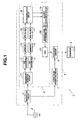
- Fig. 1 is a configuration diagram showing configuration of an ultrasonic Doppler diagnosis device.
- Fig. 2 is a block diagram showing configuration of an interpolation processing unit in Fig. 1 .
- Fig. 3 is a block diagram showing configuration of first to third interpolation processing circuits in Fig. 2 .
- Fig. 4 is a first illustrative drawing illustrating action of the interpolation processing unit in Fig. 2 .
- Fig. 5 is a second illustrative drawing illustrating the action of the interpolation processing unit in Fig. 2 .
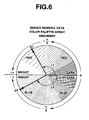
- Fig. 6 is a drawing illustrating an example of color palette array representation of velocity data of the ultrasonic Doppler diagnosis device in Fig.
- Fig. 7 is a drawing illustrating conversion of representation between the scalar array representation and the color palette array representation of the velocity data in Fig. 6 .
- Fig. 8 is a drawing illustrating an example of scalar array representation of velocity data by the representation conversion in Fig. 7 .
- Fig. 9 is a first illustrative drawing illustrating action of the first interpolation processing circuit in Fig. 3 .
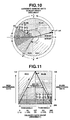
- Fig. 10 is a second illustrative drawing illustrating action of the first interpolation processing circuit in Fig. 3 .
- Fig. 11 is a third illustrative drawing illustrating action of the first interpolation processing circuit in Fig. 3 .
- Fig. 12 is a fourth illustrative drawing illustrating action of the first interpolation processing circuit in Fig. 3 .
- Fig. 13 is a fifth illustrative drawing illustrating action of the first interpolation processing circuit in Fig. 3 .
- an ultrasonic Doppler diagnosis device 1 includes a probe 2 for transmitting and receiving an ultrasonic wave to/from a living body (not shown).
- the probe 2 connects to a transceiver circuit 5 for transmitting an electric signal to the living body (not shown) in a pre-determined repeating cycle, and for receiving a received signal of the probe 2 that receives a reflected wave reflected by a kinetic reflector such as a blood flow within the living body.
- the transceiver circuit 5 herein is configured to scan an ultrasonic pulse beam emitted from the probe 2 by mechanical or electrical angle deflection, for example, and to periodically scan a living body by the ultrasonic pulse beam or to stop the scan by a desired deflection angle.
- the ultrasonic Doppler diagnosis device 1 further comprises a B-mode image generating circuit 7 for detecting a received signal received by the transceiver circuit 5 and generating a B-mode image, a Doppler image generating unit 6 for generating a Doppler image by color flow mapping (CFM), and a synthetic circuit 8 for displaying a synthesized image on a monitor, in which the synthesized image is produced by synthesization of the B-mode image and the Doppler image.
- a B-mode image generating circuit 7 for detecting a received signal received by the transceiver circuit 5 and generating a B-mode image
- a Doppler image generating unit 6 for generating a Doppler image by color flow mapping (CFM)
- CFM color flow mapping
- the Doppler image generating unit 6 includes a quadrature detection circuit 11 for assigning the received signal received by the transceiver circuit 5 to orthogonal coordinates.
- the quadrature detection circuit 11 connects to A/D converters 12 and 13 for converting an output of the quadrature detection circuit 11 to digital data.
- the quadrature detection circuit 11 herein performs known quadrature detection processing on an inputted analog signal to output two signals that include only shift frequencies and have phases differing from each other by 90° to the A/D converters 12 and 13.
- the ultrasonic Doppler diagnosis device 1 also includes, in post-stages of the A/D converters 12 and 13, memories 14 and 15 that store the converted digital data, MTI (Moving Target Indicator) filters 16 and 17 for removing a component that moves at a low velocity such as a living body from the digital data stored in the memories 14 and 15 using known processing, and for outputting I data (In Phase data) and Q data (Quadrature data) of a kinetic reflector, and an autocorrelation circuit 18 for performing complex autocorrelation processing on the I data and Q data from the MTI filters 16 and 17.
- MTI Microving Target Indicator
- the Doppler image generating unit 6 further comprises a velocity arithmetic circuit 19 for calculating the velocity of a blood flow, for example, from the processed signal subjected to the complex autocorrelation processing by the autocorrelation circuit 18, an interpolation processing unit 20 for interpolating the velocity data calculated by the velocity arithmetic circuit 19, and a DSC (digital scan converter) 21 for converting a value of the velocity data from the interpolation processing unit 20 to a brightness value depending on the velocity to output a Doppler color image to the synthetic circuit 8.
- a velocity arithmetic circuit 19 for calculating the velocity of a blood flow, for example, from the processed signal subjected to the complex autocorrelation processing by the autocorrelation circuit 18, an interpolation processing unit 20 for interpolating the velocity data calculated by the velocity arithmetic circuit 19, and a DSC (digital scan converter) 21 for converting a value of the velocity data from the interpolation processing unit 20 to a brightness value depending on the velocity to output a Do
- the interpolation processing unit 20 is configured by three interpolation processing circuits, i.e., first to third interpolation processing circuits 20a, 20b and 20c, as shown in Fig. 2 .
- the interpolation processing unit 20 will be described later in detail.
- Each of the first to third interpolation processing circuits 20a, 20b and 20c is configured by a data identifying unit 51, a data converting unit 52, a data interpolating unit 53, a data reconverting unit 54 and four switches SW1 to SW4, as shown in Fig. 3 .
- the first to third interpolation processing circuits 20a, 20b and 20c will be described later in detail.
- the ultrasonic Doppler diagnosis device 1 transmits an ultrasonic pulse from the transceiver circuit 5 via the probe 2 in a pre-determined repeating cycle, and receives a reflected wave emitted from the transceiver circuit 5 and reflected by a kinetic reflector such as a blood flow.
- the reflected wave received by the transceiver circuit 5 is further detected by the quadrature detection circuit 11.
- a Doppler shift signal detected by the quadrature detection circuit 11 is digitized by the A/D converters 12 and 13 and stored in the memories 14 and 15.
- I data In Phase data
- Q data Quadrature data
- the autocorrelation circuit 18 obtains an argument from the I data and Q data, and outputs calculated argument data to the velocity arithmetic circuit 19.
- the velocity arithmetic circuit 19 calculates velocity data of a kinetic reflector such as a blood flow from the argument data, and outputs the calculated velocity data to the interpolation processing unit 20.
- the interpolation processing unit 20 performs interpolation processing on the velocity data, as described later.
- An output from the interpolation processing unit 20 is converted to two-dimensional coordinates by the DSC 21, synthesized with a B-mode image from the B-mode image generating circuit 7 by the synthetic circuit 8, and displayed on a monitor 3.
- the interpolation processing unit 20 will be described herein. Suppose that velocity data at intersections where sound lines and scanning lines intersect are x00, x01, x10 and x11, as shown in Fig. 4 .
- ⁇ is a correction coefficient at a sound line position and ⁇ is a correction coefficient at a scanning line position.
- the velocity arithmetic circuit 19 calculates velocity data of a kinetic reflector such as a blood flow from argument data.
- a kinetic reflector such as a blood flow from argument data.
- velocity data k1 and k2 are calculated from arguments ⁇ 1 and ⁇ 2 of the respective complex vectors P1 and P2.
- argument data contains sign information indicating positive or negative in the highest-order bit of the data, so that argument data in a red region is represented correspondently to 0 to + ⁇ in the brightness: dark to bright, while argument data in a blue region is represented correspondently to 0 to - ⁇ in brightness: dark to bright.
- color palette array such an array of signed numeric data (a left array in Fig. 7 ) is referred to as a color palette array.
- the velocity arithmetic circuit 19 does not handle the highest-order bit as a sign contrary to the argument data containing a sign, but as a numeric value to calculate velocity data. Specifically, if argument data is - ⁇ /2 (in a blue region), for example, then a highest-order bit indicating a sign is "1" so that velocity data as numeric value data containing a sign is "-63 ", while velocity data considering a sign as a part of a numeric value is "191".
- argument data is + ⁇ /2 (in a red region)
- a highest-order bit indicating a sign is "0" so that velocity data as numeric value data containing a sign is "+63 ", while velocity data considering a sign as a part of a numeric value is "63".
- Argument data is represented as an array of unsigned numeric data (hereinafter, a scalar array) as shown in a right side in Fig. 7 based on unsigned numeric data being velocity data considering a sign as a part of a numeric value.
- the velocity arithmetic circuit 19 handles unsigned numeric data of the scalar array as velocity data.
- Fig. 8 The complex vectors P1 and P2 based on the scalar array are shown in Fig. 8 .
- arguments ( ⁇ 1, ⁇ 2) of the complex vectors P1 and P2 shown in Fig. 6 are represented as arguments (-( ⁇ - ⁇ 1), ⁇ - ⁇ 2).
- numeric value representing velocity data considering a sign as a part of a numeric value (unsigned numeric data) is underlined.
- numeric value representing numeric value data containing a sign (signed numeric data) is attached with a sign (+ or -).
- first interpolation processing circuit 20a the second and third interpolation processing circuits 20b and 20c also act similarly.
- the first interpolation processing circuit 20a will be described as an example.
- the first interpolation processing circuit 20a judges whether or not one of velocity data of two inputted scalar arrays is a value of "192 to 255 (+ ⁇ /2 to + ⁇ ): darker blue side” and the other is a value of "0 to 63 (- ⁇ to - ⁇ /2): darker red side” by the data identifying unit 51 (see Fig. 3 ).
- the data identifying unit 51 controls the switches SW1 to SW4 (see Fig. 3 ) to convert two scalar arrays of velocity data to color palette arrays of velocity data by the data converting unit 52 (see Fig. 3 ), and outputs the result to the data interpolating unit 53 (see Fig. 3 ).
- the data interpolating unit 53 interpolates the velocity data based on vector operation on complex spaces in the color palette arrays, as shown in Figs. 12 and 13 .
- the data reconverting unit 54 (see Fig. 3 ) reversely converts the velocity data from the color palette arrays to scalar arrays to output the result as an interpolation processing result of the first interpolation processing circuit 20a.
- the circuit 20a judges that one is not a value of "192 to 255 (+ ⁇ /2 to + ⁇ ): darker blue side", and the other is not a value of "0 to 63 (- ⁇ to - ⁇ /2): darker red side", then the data identifying unit 51 (see Fig. 3 ) outputs two scalar arrays of velocity data to the data interpolating unit 53 (see Fig. 3 ) without causing the data converting unit 52 (see Fig. 3 ) to perform conversion processing. In that case, the data interpolating unit 53 interpolates the velocity data based on vector operation on complex spaces in the scalar arrays to output the result as an interpolation processing result of the first interpolation processing circuit 20a, as shown in Figs. 12 and 13 , for example.
- the data converting unit 52, the data interpolating unit 53 and the data reconverting unit 54 switch between vector operation on a complex space based on a scalar array and vector operation on the complex space based on a color palette array to execute interpolation processing.
- aliasing disadvantages in interpolation processing on velocity data can be surely solved using an interpolating circuit of known and simple conventional circuit configuration through simple numeric value determination processing.
Landscapes
- Engineering & Computer Science (AREA)
- Physics & Mathematics (AREA)
- Remote Sensing (AREA)
- Radar, Positioning & Navigation (AREA)
- Health & Medical Sciences (AREA)
- Life Sciences & Earth Sciences (AREA)
- Computer Networks & Wireless Communication (AREA)
- Acoustics & Sound (AREA)
- General Physics & Mathematics (AREA)
- Pathology (AREA)
- Public Health (AREA)
- Medical Informatics (AREA)
- Molecular Biology (AREA)
- Surgery (AREA)
- Animal Behavior & Ethology (AREA)
- General Health & Medical Sciences (AREA)
- Heart & Thoracic Surgery (AREA)
- Veterinary Medicine (AREA)
- Biomedical Technology (AREA)
- Radiology & Medical Imaging (AREA)
- Nuclear Medicine, Radiotherapy & Molecular Imaging (AREA)
- Biophysics (AREA)
- Hematology (AREA)
- Ultra Sonic Daignosis Equipment (AREA)
Abstract
Description
- The present invention relates to an ultrasonic Doppler diagnosis device for measuring the velocity of a kinetic reflector such as a blood flow within a living body.
- An ultrasonic Doppler diagnosis device has been known for measuring a blood flow velocity within a living body, for example. When such an ultrasonic Doppler diagnosis device displays a two-dimensional Doppler view to represent spatial distribution of a velocity of a kinetic reflector such as a blood flow, the device passes a Doppler shift signal through an autocorrelator, obtains an average frequency from complex output data from the autocorrelator by an operation, and spatially interpolates the calculated average frequency for display.
- However, there is a problem in that for frequency aliasing caused around a Nyquist frequency decided depending on a sampling frequency of a Doppler shift signal, a maximum value of a positive velocity (bright red) and a maximum value of a negative velocity (bright blue) are averaged, so that an average frequency is interpolated in incorrect data (a dark color with a velocity being approximately 0) where bright blue or bright red should be interpolated in the correct way.
- In order to solve the problem as above, for example,
Japanese Patent Laid-Open No. 2678124 - However, the above ultrasonic Doppler diagnosis device according to
Japanese Patent Laid-Open No. 2678124 - In view of the above circumstances, it is an object of the present invention to provide an ultrasonic Doppler diagnosis device that can solve the disadvantages of data interpolation due to frequency aliasing by simple circuit configuration using easy numeric value array conversion processing.
- An ultrasonic Doppler diagnosis device according to the present invention comprises: ultrasonic transceiver means for emitting and scanning an ultrasonic wave and for transmitting and receiving the wave to a kinetic reflector; velocity data calculating means for extracting a Doppler shift signal using an ultrasonic signal from the kinetic reflector transmitted and received by the ultrasonic transceiver means, and for calculating velocity data at an intersection of a sound line and a scanning line of the kinetic reflector; velocity data interpolating means for interpolating the velocity data between the sound line and the scanning line and generating the interpolated velocity data; and color image generating means for generating a color flow mapping image of the kinetic reflector based on the velocity data and the interpolated velocity data, in which the velocity data interpolating means includes numeric value determining means for determining a plurality of values of the velocity data and the interpolated velocity data, and if a result of the determination is a pre-determined determination result based on the determination result of the numeric value determining means, the velocity data and the interpolated velocity data are converted to a first numeric value array to generate interpolated velocity data.
-
-
Fig. 1 is a configuration diagram showing configuration of an ultrasonic Doppler diagnosis device according to a first embodiment of the present invention; -
Fig. 2 is a block diagram showing configuration of an interpolation processing unit inFig. 1 ; -
Fig. 3 is a block diagram showing configuration of first to third interpolation processing circuits inFig. 2 ; -
Fig. 4 is a first illustrative drawing illustrating action of the interpolation processing unit inFig. 2 ; -
Fig. 5 is a second illustrative drawing illustrating the action of the interpolation processing unit inFig. 2 ; -
Fig. 6 is a drawing illustrating an example of color palette array representation of velocity data of the ultrasonic Doppler diagnosis device inFig. 1 ; -
Fig. 7 is a drawing illustrating conversion of representation between the scalar array representation and the color palette array representation of the velocity data inFig. 6 ; -
Fig. 8 is a drawing illustrating an example of scalar array representation of velocity data by the representation conversion inFig. 7 ; -
Fig. 9 is a first illustrative drawing illustrating action of the first interpolation processing circuit inFig. 3 ; -
Fig. 10 is a second illustrative drawing illustrating action of the first interpolation processing circuit inFig. 3 ; -
Fig. 11 is a third illustrative drawing illustrating action of the first interpolation processing circuit inFig. 3 ; -
Fig. 12 is a fourth illustrative drawing illustrating action of the first interpolation processing circuit inFig. 3 ; and -
Fig. 13 is a fifth illustrative drawing illustrating action of the first interpolation processing circuit inFig. 3 . - The following will describe an embodiment of the present invention with reference to the drawings.
-
Figs. 1 to 13 relate to a first embodiment of the present invention.Fig. 1 is a configuration diagram showing configuration of an ultrasonic Doppler diagnosis device.Fig. 2 is a block diagram showing configuration of an interpolation processing unit inFig. 1 .Fig. 3 is a block diagram showing configuration of first to third interpolation processing circuits inFig. 2 .Fig. 4 is a first illustrative drawing illustrating action of the interpolation processing unit inFig. 2 .Fig. 5 is a second illustrative drawing illustrating the action of the interpolation processing unit inFig. 2 .Fig. 6 is a drawing illustrating an example of color palette array representation of velocity data of the ultrasonic Doppler diagnosis device inFig. 1 .Fig. 7 is a drawing illustrating conversion of representation between the scalar array representation and the color palette array representation of the velocity data inFig. 6 .Fig. 8 is a drawing illustrating an example of scalar array representation of velocity data by the representation conversion inFig. 7 .Fig. 9 is a first illustrative drawing illustrating action of the first interpolation processing circuit inFig. 3 .Fig. 10 is a second illustrative drawing illustrating action of the first interpolation processing circuit inFig. 3 .Fig. 11 is a third illustrative drawing illustrating action of the first interpolation processing circuit inFig. 3 .Fig. 12 is a fourth illustrative drawing illustrating action of the first interpolation processing circuit inFig. 3 .Fig. 13 is a fifth illustrative drawing illustrating action of the first interpolation processing circuit inFig. 3 . - As shown in
Fig. 1 , an ultrasonicDoppler diagnosis device 1 according to the present embodiment includes aprobe 2 for transmitting and receiving an ultrasonic wave to/from a living body (not shown). Theprobe 2 connects to atransceiver circuit 5 for transmitting an electric signal to the living body (not shown) in a pre-determined repeating cycle, and for receiving a received signal of theprobe 2 that receives a reflected wave reflected by a kinetic reflector such as a blood flow within the living body. - The
transceiver circuit 5 herein is configured to scan an ultrasonic pulse beam emitted from theprobe 2 by mechanical or electrical angle deflection, for example, and to periodically scan a living body by the ultrasonic pulse beam or to stop the scan by a desired deflection angle. - The ultrasonic
Doppler diagnosis device 1 further comprises a B-mode image generating circuit 7 for detecting a received signal received by thetransceiver circuit 5 and generating a B-mode image, a Dopplerimage generating unit 6 for generating a Doppler image by color flow mapping (CFM), and asynthetic circuit 8 for displaying a synthesized image on a monitor, in which the synthesized image is produced by synthesization of the B-mode image and the Doppler image. - The Doppler
image generating unit 6 includes aquadrature detection circuit 11 for assigning the received signal received by thetransceiver circuit 5 to orthogonal coordinates. Thequadrature detection circuit 11 connects to A/D converters quadrature detection circuit 11 to digital data. - The
quadrature detection circuit 11 herein performs known quadrature detection processing on an inputted analog signal to output two signals that include only shift frequencies and have phases differing from each other by 90° to the A/D converters - The ultrasonic
Doppler diagnosis device 1 also includes, in post-stages of the A/D converters memories filters memories autocorrelation circuit 18 for performing complex autocorrelation processing on the I data and Q data from theMTI filters - The Doppler
image generating unit 6 further comprises a velocityarithmetic circuit 19 for calculating the velocity of a blood flow, for example, from the processed signal subjected to the complex autocorrelation processing by theautocorrelation circuit 18, aninterpolation processing unit 20 for interpolating the velocity data calculated by the velocityarithmetic circuit 19, and a DSC (digital scan converter) 21 for converting a value of the velocity data from theinterpolation processing unit 20 to a brightness value depending on the velocity to output a Doppler color image to thesynthetic circuit 8. - The
interpolation processing unit 20 is configured by three interpolation processing circuits, i.e., first to thirdinterpolation processing circuits Fig. 2 . Theinterpolation processing unit 20 will be described later in detail. - Each of the first to third
interpolation processing circuits data identifying unit 51, adata converting unit 52, adata interpolating unit 53, adata reconverting unit 54 and four switches SW1 to SW4, as shown inFig. 3 . The first to thirdinterpolation processing circuits - Next, action of the present embodiment configured as described in the above will be described. The ultrasonic
Doppler diagnosis device 1 according to the present embodiment transmits an ultrasonic pulse from thetransceiver circuit 5 via theprobe 2 in a pre-determined repeating cycle, and receives a reflected wave emitted from thetransceiver circuit 5 and reflected by a kinetic reflector such as a blood flow. - The reflected wave received by the
transceiver circuit 5 is further detected by thequadrature detection circuit 11. A Doppler shift signal detected by thequadrature detection circuit 11 is digitized by the A/D converters memories - Then, I data (In Phase data) and Q data (Quadrature data) of a kinetic reflector are extracted from the Doppler shift signal stored in the
memories MTI filters autocorrelation circuit 18. Theautocorrelation circuit 18 obtains an argument from the I data and Q data, and outputs calculated argument data to the velocityarithmetic circuit 19. The velocityarithmetic circuit 19 calculates velocity data of a kinetic reflector such as a blood flow from the argument data, and outputs the calculated velocity data to theinterpolation processing unit 20. - The
interpolation processing unit 20 performs interpolation processing on the velocity data, as described later. An output from theinterpolation processing unit 20 is converted to two-dimensional coordinates by theDSC 21, synthesized with a B-mode image from the B-mode image generating circuit 7 by thesynthetic circuit 8, and displayed on amonitor 3. - The
interpolation processing unit 20 will be described herein. Suppose that velocity data at intersections where sound lines and scanning lines intersect are x00, x01, x10 and x11, as shown inFig. 4 . First, theinterpolation processing unit 20 calculates velocity data u0 at a position (coordinates) between the intersections from velocity data: x00 of an intersection (sound line position, scanning line position) = (Line, Point) and velocity data: x01 of an intersection (sound line position, scanning line position) = (Ling, Point+1) in the firstinterpolation processing circuit 20a by the first to thirdinterpolation processing circuit Fig. 2 ) by performing interpolation operation using the following equation (1) by interpolation processing, as shown inFig. 5 .
- Similarly, the second
interpolation processing circuit 20b calculates velocity data u1 at a position (coordinates) between the intersections from velocity data: x10 of an intersection (sound line position, scanning line position) = (Line+ 1, Point) and velocity data: x11 of an intersection (sound line position, scanning line position) = (Line+ 1, Point+1) by performing interpolation operation using the following equation (2) by interpolation processing.
- Then, the second
interpolation processing circuit 20b performs interpolation processing on the velocity data u0 and the velocity data u1, and calculates velocity data v0 between the velocity data u0 and the velocity data u1 by performing interpolation operation using the following equation (3):
- In the above equations, α is a correction coefficient at a sound line position and β is a correction coefficient at a scanning line position.
- As described in the above, the velocity
arithmetic circuit 19 calculates velocity data of a kinetic reflector such as a blood flow from argument data. Conceptually describing, if complex vectors P1 and P2 including I data and Q data of a kinetic reflector are as shown inFig. 6 , velocity data k1 and k2 are calculated from arguments φ1 and φ2 of the respective complex vectors P1 and P2. - Specifically, according to standard ultrasonic Doppler display, if a blood flow gets close at an intersection (sound line position, scanning line position), velocity data is represented in red; if a blood flow gets away, velocity data is represented in blue; and a level of the velocity is represented by brightness, as shown in
Fig. 7 . Meanwhile, argument data contains sign information indicating positive or negative in the highest-order bit of the data, so that argument data in a red region is represented correspondently to 0 to +π in the brightness: dark to bright, while argument data in a blue region is represented correspondently to 0 to -π in brightness: dark to bright. - Hereinafter, such an array of signed numeric data (a left array in
Fig. 7 ) is referred to as a color palette array. - On the other hand, the velocity
arithmetic circuit 19 does not handle the highest-order bit as a sign contrary to the argument data containing a sign, but as a numeric value to calculate velocity data. Specifically, if argument data is -π/2 (in a blue region), for example, then a highest-order bit indicating a sign is "1" so that velocity data as numeric value data containing a sign is "-63 ", while velocity data considering a sign as a part of a numeric value is "191". If argument data is +π/2 (in a red region), then a highest-order bit indicating a sign is "0" so that velocity data as numeric value data containing a sign is "+63 ", while velocity data considering a sign as a part of a numeric value is "63". Argument data is represented as an array of unsigned numeric data (hereinafter, a scalar array) as shown in a right side inFig. 7 based on unsigned numeric data being velocity data considering a sign as a part of a numeric value. The velocityarithmetic circuit 19 handles unsigned numeric data of the scalar array as velocity data. - The complex vectors P1 and P2 based on the scalar array are shown in
Fig. 8 . InFig. 8 , arguments (φ1, φ2) of the complex vectors P1 and P2 shown inFig. 6 are represented as arguments (-(π-φ1), π-φ2). - Hereinafter, a numeric value representing velocity data considering a sign as a part of a numeric value (unsigned numeric data) is underlined. Meanwhile, a numeric value representing numeric value data containing a sign (signed numeric data) is attached with a sign (+ or -).
- As shown in
Fig. 9 , if one of two velocity data is a value of 233 within "192 to 255 (+π/2 to +π): darker blue side", for example, and the other is a value of 43 within "0 to 63 (-π to π/2): darker red side", for example, in a scalar array, then when the firstinterpolation processing circuit 20a of theinterpolation processing unit 20 performs interpolation processing on the two velocity data, a value of 131 is calculated as a result of the interpolation. The result is different from a result of interpolation based on the original vector operation, as shown inFigs. 10 and 11 . - The above description is not limited to the first
interpolation processing circuit 20a, but the second and thirdinterpolation processing circuits interpolation processing circuit 20a will be described as an example. - According to the present embodiment, as shown in
Fig. 9 , the firstinterpolation processing circuit 20a judges whether or not one of velocity data of two inputted scalar arrays is a value of "192 to 255 (+π/2 to +π): darker blue side" and the other is a value of "0 to 63 (-π to -π/2): darker red side" by the data identifying unit 51 (seeFig. 3 ). - If the
circuit 20a judges one is a value of "192 to 255 (+π/2 to +π): darker blue side" and the other is a value of "0 to 63 (-π to -π/2): darker red side", the data identifying unit 51 (seeFig. 3 ) controls the switches SW1 to SW4 (seeFig. 3 ) to convert two scalar arrays of velocity data to color palette arrays of velocity data by the data converting unit 52 (seeFig. 3 ), and outputs the result to the data interpolating unit 53 (seeFig. 3 ). In that case, thedata interpolating unit 53 interpolates the velocity data based on vector operation on complex spaces in the color palette arrays, as shown inFigs. 12 and 13 . Then, based on the velocity data interpolated in thedata interpolating unit 53, the data reconverting unit 54 (seeFig. 3 ) reversely converts the velocity data from the color palette arrays to scalar arrays to output the result as an interpolation processing result of the firstinterpolation processing circuit 20a. - Otherwise, if the
circuit 20a judges that one is not a value of "192 to 255 (+π/2 to +π): darker blue side", and the other is not a value of "0 to 63 (-π to -π/2): darker red side", then the data identifying unit 51 (seeFig. 3 ) outputs two scalar arrays of velocity data to the data interpolating unit 53 (seeFig. 3 ) without causing the data converting unit 52 (seeFig. 3 ) to perform conversion processing. In that case, thedata interpolating unit 53 interpolates the velocity data based on vector operation on complex spaces in the scalar arrays to output the result as an interpolation processing result of the firstinterpolation processing circuit 20a, as shown inFigs. 12 and 13 , for example. - As described in the above, according to the present embodiment, after the
data identifying unit 51 determines a value of velocity data, thedata converting unit 52, thedata interpolating unit 53 and thedata reconverting unit 54 switch between vector operation on a complex space based on a scalar array and vector operation on the complex space based on a color palette array to execute interpolation processing. As such, according to the present embodiment, aliasing disadvantages in interpolation processing on velocity data can be surely solved using an interpolating circuit of known and simple conventional circuit configuration through simple numeric value determination processing. - The present invention is not limited to the above embodiment, but various changes or modifications are possible without departing from the scope of the present invention.
Claims (8)
- An ultrasonic Doppler diagnosis device comprising:ultrasonic transceiver means for emitting and scanning an ultrasonic wave and for transmitting and receiving the wave to a kinetic reflector;velocity data calculating means for extracting a Doppler shift signal using an ultrasonic signal from the kinetic reflector transmitted and received by the ultrasonic transceiver means, and for calculating velocity data at an intersection of a sound line and a scanning line of the kinetic reflector;velocity data interpolating means for interpolating the velocity data between the sound line and the scanning line and generating the interpolated velocity data; andcolor image generating means for generating a color flow mapping image of the kinetic reflector based on the velocity data and the interpolated velocity data,wherein the velocity data interpolating means includes numeric value determining means for determining a plurality of values of the velocity data and the interpolated velocity data, andif a result of the determination is a pre-determined determination result based on the determination result of the numeric value determining means, the velocity data and the interpolated velocity data are converted to a first numeric value array to generate interpolated velocity data.
- The ultrasonic Doppler diagnosis device according to claim 1, wherein:the velocity data interpolating means is hierarchically configured by a plurality of data hierarchy interpolating means for generating the interpolated velocity data from the two velocity data.
- The ultrasonic Doppler diagnosis device according to claim 1, wherein:the numeric value determining means judges, if a numeric value of one of the two velocity data is within a first threshold range and a numeric value of the other velocity data is within the first threshold range, the result as the pre-determined determination result.
- The ultrasonic Doppler diagnosis device according to claim 2, wherein:the numeric value determining means judges, if a numeric value of one of the two velocity data is within a first threshold range and a numeric value of the other velocity data is within the first threshold range, the result as the pre-determined determination result.
- The ultrasonic Doppler diagnosis device according to claim 1, wherein:the kinetic reflector is a blood flow within a living body.
- The ultrasonic Doppler diagnosis device according to claim 2, wherein:the kinetic reflector is a blood flow within a living body.
- The ultrasonic Doppler diagnosis device according to claim 3, wherein:the kinetic reflector is a blood flow within a living body.
- The ultrasonic Doppler diagnosis device according to claim 4, wherein:the kinetic reflector is a blood flow within a living body.
Applications Claiming Priority (2)
| Application Number | Priority Date | Filing Date | Title |
|---|---|---|---|
| JP2006346271 | 2006-12-22 | ||
| JP2007245696A JP2008173448A (en) | 2006-12-22 | 2007-09-21 | Ultrasonic Doppler diagnostic device |
Publications (3)
| Publication Number | Publication Date |
|---|---|
| EP1935345A2 true EP1935345A2 (en) | 2008-06-25 |
| EP1935345A3 EP1935345A3 (en) | 2010-03-31 |
| EP1935345B1 EP1935345B1 (en) | 2017-09-13 |
Family
ID=39111452
Family Applications (1)
| Application Number | Title | Priority Date | Filing Date |
|---|---|---|---|
| EP07024621.0A Not-in-force EP1935345B1 (en) | 2006-12-22 | 2007-12-19 | Ultrasonic doppler diagnosis device |
Country Status (2)
| Country | Link |
|---|---|
| US (1) | US8088069B2 (en) |
| EP (1) | EP1935345B1 (en) |
Families Citing this family (3)
| Publication number | Priority date | Publication date | Assignee | Title |
|---|---|---|---|---|
| JP5732461B2 (en) * | 2009-08-11 | 2015-06-10 | 日立アロカメディカル株式会社 | Ultrasound image diagnosis method and ultrasound image diagnosis apparatus |
| EP4419940A4 (en) * | 2021-10-21 | 2025-04-09 | Evident Canada, Inc. | Color representation of complex-valued ndt data |
| JP2025017714A (en) * | 2023-07-25 | 2025-02-06 | 富士フイルム株式会社 | Ultrasound diagnostic device and program |
Family Cites Families (8)
| Publication number | Priority date | Publication date | Assignee | Title |
|---|---|---|---|---|
| JPS6443238A (en) | 1987-08-12 | 1989-02-15 | Toshiba Corp | Ultrasonic blood flow imaging apparatus |
| JP2763126B2 (en) | 1989-02-10 | 1998-06-11 | 株式会社東芝 | Color ultrasonic diagnostic equipment |
| JP2950600B2 (en) | 1990-10-26 | 1999-09-20 | 株式会社東芝 | Color Doppler ultrasound system |
| JP2678124B2 (en) | 1993-01-08 | 1997-11-17 | アロカ株式会社 | Ultrasound Doppler diagnostic device |
| US5429137A (en) | 1994-06-03 | 1995-07-04 | Siemens Medical Systems, Inc. | Acoustic scan conversion method and apparatus for velocity flow |
| JPH09187458A (en) | 1996-01-09 | 1997-07-22 | Toshiba Corp | Ultrasonic diagnostic apparatus and color flow mapping image display method |
| US6115485A (en) * | 1997-10-06 | 2000-09-05 | General Electric Company | Introducing reduced data set information into a primary image data set |
| JP4161146B2 (en) | 1998-12-24 | 2008-10-08 | 株式会社Ihi | Welded part imaging device using double laser illumination |
-
2007
- 2007-12-18 US US11/958,810 patent/US8088069B2/en active Active
- 2007-12-19 EP EP07024621.0A patent/EP1935345B1/en not_active Not-in-force
Also Published As
| Publication number | Publication date |
|---|---|
| US20080154134A1 (en) | 2008-06-26 |
| US8088069B2 (en) | 2012-01-03 |
| EP1935345B1 (en) | 2017-09-13 |
| EP1935345A3 (en) | 2010-03-31 |
Similar Documents
| Publication | Publication Date | Title |
|---|---|---|
| EP2609868B1 (en) | Providing user interface in ultrasound system | |
| EP0725282A2 (en) | Method of displaying ultrasonic images and apparatus for ultrasonic diagnosis | |
| US5188113A (en) | Ultrasonic diagnosis apparatus | |
| EP2609871A1 (en) | Providing vector doppler image based on decision data in ultrasound system | |
| US8306296B2 (en) | Clutter signal filtering using eigenvectors in an ultrasound system | |
| EP2455753A2 (en) | Providing Color Doppler Image Based on Qualification Curve Information in Ultrasound System | |
| EP2609870A1 (en) | Providing turbulent flow information based on vector doppler in ultrasound system | |
| EP1079242B1 (en) | Ultrasound diagnostic apparatus | |
| CN103181788A (en) | Ultrasound system and method of estimating at least one particle | |
| EP2609866B1 (en) | Providing motion mode image in ultrasound system | |
| EP1935345B1 (en) | Ultrasonic doppler diagnosis device | |
| JPS63317137A (en) | Ultrasonic blood flow imaging apparatus | |
| JP2009268734A (en) | Ultrasound observation apparatus | |
| CN112043307B (en) | Ultrasonic diagnostic apparatus, control method thereof, and computer-readable recording medium | |
| EP2610640B1 (en) | Ultrasound system and method for detecting vector information using transmission delays | |
| US20130165793A1 (en) | Providing doppler information of target object based on vector doppler in ultrasound system | |
| EP2609869A1 (en) | Providing particle flow image in ultrasound system | |
| CN201160858Y (en) | Ultrasonic Doppler Diagnostic Device | |
| US20070073152A1 (en) | Systems and methods for acquiring images simultaneously | |
| JP2938125B2 (en) | Ultrasound diagnostic equipment | |
| US20120197125A1 (en) | Ultrasound diagnostic device | |
| JP2782905B2 (en) | Ultrasound diagnostic equipment | |
| JP4918344B2 (en) | Image generation method and ultrasonic diagnostic apparatus | |
| JPH06205774A (en) | Ultrasonic doppler diagnostic system | |
| JPH04146737A (en) | Ultrasonic diagnostic device |
Legal Events
| Date | Code | Title | Description |
|---|---|---|---|
| PUAI | Public reference made under article 153(3) epc to a published international application that has entered the european phase |
Free format text: ORIGINAL CODE: 0009012 |
|
| AK | Designated contracting states |
Kind code of ref document: A2 Designated state(s): AT BE BG CH CY CZ DE DK EE ES FI FR GB GR HU IE IS IT LI LT LU LV MC MT NL PL PT RO SE SI SK TR |
|
| AX | Request for extension of the european patent |
Extension state: AL BA HR MK RS |
|
| PUAL | Search report despatched |
Free format text: ORIGINAL CODE: 0009013 |
|
| AK | Designated contracting states |
Kind code of ref document: A3 Designated state(s): AT BE BG CH CY CZ DE DK EE ES FI FR GB GR HU IE IS IT LI LT LU LV MC MT NL PL PT RO SE SI SK TR |
|
| AX | Request for extension of the european patent |
Extension state: AL BA HR MK RS |
|
| 17P | Request for examination filed |
Effective date: 20100602 |
|
| 17Q | First examination report despatched |
Effective date: 20100712 |
|
| AKX | Designation fees paid |
Designated state(s): DE FR GB |
|
| RAP1 | Party data changed (applicant data changed or rights of an application transferred) |
Owner name: OLYMPUS CORPORATION |
|
| RAP1 | Party data changed (applicant data changed or rights of an application transferred) |
Owner name: OLYMPUS CORPORATION |
|
| RAP1 | Party data changed (applicant data changed or rights of an application transferred) |
Owner name: OLYMPUS CORPORATION |
|
| RIN1 | Information on inventor provided before grant (corrected) |
Inventor name: SABATA, TOMOHIRO |
|
| GRAP | Despatch of communication of intention to grant a patent |
Free format text: ORIGINAL CODE: EPIDOSNIGR1 |
|
| RIC1 | Information provided on ipc code assigned before grant |
Ipc: A61B 8/06 20060101AFI20170321BHEP Ipc: G01S 15/89 20060101ALI20170321BHEP Ipc: G01S 7/52 20060101ALI20170321BHEP |
|
| INTG | Intention to grant announced |
Effective date: 20170412 |
|
| GRAS | Grant fee paid |
Free format text: ORIGINAL CODE: EPIDOSNIGR3 |
|
| GRAA | (expected) grant |
Free format text: ORIGINAL CODE: 0009210 |
|
| AK | Designated contracting states |
Kind code of ref document: B1 Designated state(s): DE FR GB |
|
| REG | Reference to a national code |
Ref country code: GB Ref legal event code: FG4D |
|
| RIN1 | Information on inventor provided before grant (corrected) |
Inventor name: SABATA, TOMOHIRO |
|
| REG | Reference to a national code |
Ref country code: DE Ref legal event code: R096 Ref document number: 602007052341 Country of ref document: DE |
|
| REG | Reference to a national code |
Ref country code: DE Ref legal event code: R097 Ref document number: 602007052341 Country of ref document: DE |
|
| PLBE | No opposition filed within time limit |
Free format text: ORIGINAL CODE: 0009261 |
|
| STAA | Information on the status of an ep patent application or granted ep patent |
Free format text: STATUS: NO OPPOSITION FILED WITHIN TIME LIMIT |
|
| 26N | No opposition filed |
Effective date: 20180614 |
|
| GBPC | Gb: european patent ceased through non-payment of renewal fee |
Effective date: 20171219 |
|
| REG | Reference to a national code |
Ref country code: FR Ref legal event code: ST Effective date: 20180831 |
|
| PG25 | Lapsed in a contracting state [announced via postgrant information from national office to epo] |
Ref country code: FR Free format text: LAPSE BECAUSE OF NON-PAYMENT OF DUE FEES Effective date: 20180102 |
|
| PG25 | Lapsed in a contracting state [announced via postgrant information from national office to epo] |
Ref country code: GB Free format text: LAPSE BECAUSE OF NON-PAYMENT OF DUE FEES Effective date: 20171219 |
|
| PGFP | Annual fee paid to national office [announced via postgrant information from national office to epo] |
Ref country code: DE Payment date: 20181210 Year of fee payment: 12 |
|
| REG | Reference to a national code |
Ref country code: DE Ref legal event code: R119 Ref document number: 602007052341 Country of ref document: DE |
|
| PG25 | Lapsed in a contracting state [announced via postgrant information from national office to epo] |
Ref country code: DE Free format text: LAPSE BECAUSE OF NON-PAYMENT OF DUE FEES Effective date: 20200701 |