EP1935309A2 - Vacuum cleaner. - Google Patents
Vacuum cleaner. Download PDFInfo
- Publication number
- EP1935309A2 EP1935309A2 EP07290982A EP07290982A EP1935309A2 EP 1935309 A2 EP1935309 A2 EP 1935309A2 EP 07290982 A EP07290982 A EP 07290982A EP 07290982 A EP07290982 A EP 07290982A EP 1935309 A2 EP1935309 A2 EP 1935309A2
- Authority
- EP
- European Patent Office
- Prior art keywords
- cleaner
- cover
- filter
- collecting unit
- casing
- Prior art date
- Legal status (The legal status is an assumption and is not a legal conclusion. Google has not performed a legal analysis and makes no representation as to the accuracy of the status listed.)
- Granted
Links
Images




Classifications
-
- A—HUMAN NECESSITIES
- A47—FURNITURE; DOMESTIC ARTICLES OR APPLIANCES; COFFEE MILLS; SPICE MILLS; SUCTION CLEANERS IN GENERAL
- A47L—DOMESTIC WASHING OR CLEANING; SUCTION CLEANERS IN GENERAL
- A47L9/00—Details or accessories of suction cleaners, e.g. mechanical means for controlling the suction or for effecting pulsating action; Storing devices specially adapted to suction cleaners or parts thereof; Carrying-vehicles specially adapted for suction cleaners
- A47L9/10—Filters; Dust separators; Dust removal; Automatic exchange of filters
- A47L9/12—Dry filters
-
- A—HUMAN NECESSITIES
- A47—FURNITURE; DOMESTIC ARTICLES OR APPLIANCES; COFFEE MILLS; SPICE MILLS; SUCTION CLEANERS IN GENERAL
- A47L—DOMESTIC WASHING OR CLEANING; SUCTION CLEANERS IN GENERAL
- A47L9/00—Details or accessories of suction cleaners, e.g. mechanical means for controlling the suction or for effecting pulsating action; Storing devices specially adapted to suction cleaners or parts thereof; Carrying-vehicles specially adapted for suction cleaners
- A47L9/10—Filters; Dust separators; Dust removal; Automatic exchange of filters
- A47L9/16—Arrangement or disposition of cyclones or other devices with centrifugal action
- A47L9/1683—Dust collecting chambers; Dust collecting receptacles
-
- A—HUMAN NECESSITIES
- A47—FURNITURE; DOMESTIC ARTICLES OR APPLIANCES; COFFEE MILLS; SPICE MILLS; SUCTION CLEANERS IN GENERAL
- A47L—DOMESTIC WASHING OR CLEANING; SUCTION CLEANERS IN GENERAL
- A47L9/00—Details or accessories of suction cleaners, e.g. mechanical means for controlling the suction or for effecting pulsating action; Storing devices specially adapted to suction cleaners or parts thereof; Carrying-vehicles specially adapted for suction cleaners
- A47L9/10—Filters; Dust separators; Dust removal; Automatic exchange of filters
-
- A—HUMAN NECESSITIES
- A47—FURNITURE; DOMESTIC ARTICLES OR APPLIANCES; COFFEE MILLS; SPICE MILLS; SUCTION CLEANERS IN GENERAL
- A47L—DOMESTIC WASHING OR CLEANING; SUCTION CLEANERS IN GENERAL
- A47L9/00—Details or accessories of suction cleaners, e.g. mechanical means for controlling the suction or for effecting pulsating action; Storing devices specially adapted to suction cleaners or parts thereof; Carrying-vehicles specially adapted for suction cleaners
- A47L9/10—Filters; Dust separators; Dust removal; Automatic exchange of filters
- A47L9/12—Dry filters
- A47L9/122—Dry filters flat
-
- A—HUMAN NECESSITIES
- A47—FURNITURE; DOMESTIC ARTICLES OR APPLIANCES; COFFEE MILLS; SPICE MILLS; SUCTION CLEANERS IN GENERAL
- A47L—DOMESTIC WASHING OR CLEANING; SUCTION CLEANERS IN GENERAL
- A47L9/00—Details or accessories of suction cleaners, e.g. mechanical means for controlling the suction or for effecting pulsating action; Storing devices specially adapted to suction cleaners or parts thereof; Carrying-vehicles specially adapted for suction cleaners
- A47L9/10—Filters; Dust separators; Dust removal; Automatic exchange of filters
- A47L9/19—Means for monitoring filtering operation
Definitions
- the present invention relates to a cleaner, and more particularly, to a vacuum cleaner, which draws in dirt or dust from a surface to be cleaned by using a suction force thus to carry out a cleaning operation.
- a vacuum cleaner generates a suction force by using a suction motor installed in a cleaner body, and draws in dust or dirt along with air from a surface to be cleaned by using the suction force.
- the drawn-in air laden with the dust or dirt is deprived of the dust or dirt while passing through a dust collecting unit, so that only the purified air is discharged to the outside of the cleaner body.
- the conventional vacuum cleaner is configured, so that as disclosed in Korean patent publication No. 2006-13855 , a filter for filtering the air from which the dirt is separated is located in the dust collecting unit, or as Korean patent No. 623916 , a filter is covered with a grill unit, which supports the filter.
- the conventional vacuum cleaner may present a problem in that if large dust or dirt is flowed into the dust collecting unit, the filter is clogged due to the large dust or dirt, thereby causing the suction motor to carry a large load thus to reduce the lifespan thereof, as well as causing a filtering efficiency for minute dust of the filter to deteriorate.
- the conventional vacuum cleaner comes inconvenient to use.
- the minute dust and the large dust or dirt are dumped together as because of structure, the dust collecting unit collects the minute dust along with the large dust or dirt.
- the conventional vacuum cleaner is inconvenient in that as far as a user does not directly draws out the filter to the outside, she or he cannot accurately grasp a contamination level of the filter. In process of confirming the contamination level of the filter as described above, the user should pick up the contaminated filter with her or his fingers or by using separate tongs. Moreover, since the filter is in a state where it is inserted in a very narrow space, it is not only difficult to draw out the filter to the outside, but also to insert it again into the narrow space.
- an aspect of the present invention is to provide a vacuum cleaner capable of maintaining a dust collecting unit and a filter assembly, which collect large dirt or dust and minute dust, respectively, in different periods according to amounts of the dirt or dust collected therein, respectively, thereby improving a separating or collecting efficiency for minute dust.
- Another aspect of the present invention is to provide a vacuum cleaner capable of easily grasping a contamination level of a filter with the naked eye.
- a vacuum cleaner including a suction motor to draw in dirt or dust into a cleaner body through a suction nozzle, a dust collecting unit to collect the dirt or dust drawn into the cleaner body and having a discharging hole to discharge air, and a filter assembly detachably joined to the cleaner body on an air discharging passage between the dust collecting unit and the suction motor, and provided as a member separate from the dust collecting unit.
- the dust collecting unit and the filter assembly which collect large dirt or dust and minute dust, respectively, can be maintained in different periods according to amounts of the dirt or dust collected therein, respectively, thereby improving a separating or collecting efficiency for the minute dust.
- the dust collecting unit may be mounted in an accommodating part horizontally projected in the front of the cleaner body and the filter assembly may be mounted in a seating space part formed in an lower side of the accommodating part, so that the filter assembly and the collecting unit are communicated with each other.
- the filter assembly is disposed below the dust collecting unit to communicate therewith.
- the filter assembly may include a casing having an opened upper part and a partly opened lower part, a cover mounted on a top of the casing to communicate with the discharging hole on an undersurface of the dust collecting unit, and at least one filter inserted into and mounted in the casing.
- at least one of the casing and the cover may be formed of transparent material.
- the cover may have a penetrated hole formed to communicate with the discharging hole, and the discharging hole and the penetrated hole may be communicated with in a sealed state with each other.
- a cover at an upper side thereof may have a recessed groove part formed in the form of a loop along an outer side of the penetrated hole, and the dust collecting unit may have a coupling projection formed corresponding to the recessed groove part along an outer side of the discharging hole to couple with the recessed groove.
- the cover has at least two gripping grooves recessed downward from an upper surface thereof, to enable the filter assembly to be gripped and drawn out from the cleaner body.
- the top of the casing may be inclined, so that a dust accumulating space, which dust or dirt included in the air discharged from the discharging hole of the dust collecting unit is accumulated, is formed above the filter inserted in the casing.
- the cover may include at least one fist supporting projection projected from a undersurface of the cover by at least one of the gripping grooves, and a second supporting projection projected from the undersurface of the cover, so that a lower end thereof is located on the same plane as that of a lower end of the fist supporting projection, and positioned in a spaced-apart relation with the fist supporting projection, and the first and the second supporting projections may support an upper surface of the filter, so that the filter is not freely moved in the casing due to a gap formed by the dust accumulating space.
- the cleaner may further include a locking part to lock the cover to the casing.
- the locking part may include at least one hook projected from one side of a undersurface of the cover adjacent to an outer circumference surface of the cover, at least one first hooking hole formed on one side of the top of the casing to accommodate and lock the hook therein, a locking lever hinged on the other side of the undersurface of the cover adjacent to the outer circumference surface of the cover and having a hanging prominence formed on the inside thereof, and at least one hanging projection formed on the other side of the top of the casing to engage with and lock the hanging prominence of the locking lever.
- the filter may include a sponge filter, and a micro filter thinner that the sponge filter.
- the filter filters the minute dust twice, so that the collecting efficiency for minute dust can be improved.
- FIG. 1 is a schematic side elevation view exemplifying a vacuum cleaner according to an exemplary embodiment of the present invention
- FIGS. 2A and 2B are schematic perspective views exemplifying mounted and dismounted states where a filter assembly is mounted in and dismounted from a cleaner body;
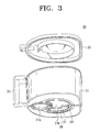
- FIG. 3 is a perspective view exemplifying a dust collecting unit of the vacuum cleaner illustrated in FIG.1 ;
- FIG. 4 is a perspective view exemplifying the filter assembly of the vacuum cleaner illustrated in FIG.1 ;
- FIG. 5 is an exploded perspective view exemplifying the filter assembly illustrated in FIG.4 ;
- FIG. 6 is a schematic side elevation view of the filter assembly as viewed in a direction of arrow A indicated in FIG. 4 ;
- FIG. 7 is a partly magnified cross-sectional view exemplifying a part B indicated in FIG. 6 .
- FIG. 1 is a schematic side elevation view exemplifying the vacuum cleaner according to the exemplary embodiment of the present invention
- FIGS. 2A and 2B are schematic perspective views exemplifying mounted and dismounted states where a filter assembly is mounted in and dismounted from a cleaner body
- FIG. 3 is a perspective view exemplifying a dust collecting unit of the vacuum cleaner illustrated in FIG.1 .
- the vacuum cleaner includes a suction nozzle 1 to draw in dust or dirt from a surface to be cleaned, an extended tube 3, a handle 5, a connecting hose 7, a cleaner body 10, a suction motor 20, a dust collecting unit 30, and a filter assembly 40.
- the connecting hose 7 is detachably coupled to the cleaner body 10 to connect the suction nozzle 1 to a hose connecting part 11 in front of the cleaner body 10 and thus to guide the dust or dirt drawn in from the surface to be cleaned, into the cleaner body 10.
- the hose connecting part 11 is communicated with an inflow hole 13 (see FIG. 2A ), which is formed in an approximate right angle to a bottom surface of the cleaner body 10 to communicate in a bent state with the hose connecting part 11. Also, referring to FIGS.
- the cleaner body 10 has an accommodating part 18 horizontally projected in the front thereof, so that the dust collecting unit 30 can be mounted in the accommodating part 18.
- a seating space part 15 is formed in a lower side of the accommodating part 18, so that the filter assembly 40 can be seated and mounted in the seating space part 15.
- the seating space part 15 and a motor chamber 9 in which the suction motor 20 is disposed are communicated by a plurality of air discharging hole 17 with each other. As a result, air passing through the filter assembly 40 can be flowed toward the suction motor 20.
- the suction motor 20 generates a suction force for drawing in the dust or dirt into the cleaner body 10 through the suction nozzle 1, and is disposed in the rear of the cleaner body 10.
- the dust collecting unit 30 includes a body 31, a lid 33, and a handle 35.
- the body 31 is detachably joined to the accommodating part 18, and as illustrated in FIG. 3 , at an undersurface thereof has a suction hole 31 a communicating with the inflow hole 13 (see FIG. 2A ) and a discharging hole 31 b communicating with a penetrated hole 43a of the filter assembly 40.
- Such a body 31 has a cyclone structure, which separates the dust or dirt drawn in together with the air therefrom by a centrifugal force and discharges the dust-removed air through the discharging hole 31 b.
- the lid 33 is detachably coupled to an upper part of the body 31 to open and close the upper part of the body 31.
- Reference numerals 37 and 38 indicate a filter and a mount to support the filter 37, respectively.
- the filter assembly 40 as an assembly formed of a member separate from the dust collecting unit 30, is disposed on a discharging passage between the duct collecting unit 30 and the suction motor 20, and includes a casing 41, a cover 43, a first filter 45 and a second filter 47.
- FIG. 4 is a perspective view exemplifying the filter assembly
- FIG. 5 is an exploded perspective view exemplifying the filter assembly
- FIG. 6 is a schematic side elevation view of the filter assembly
- FIG. 7 is a partly magnified cross-sectional view exemplifying a locking structure.
- the casing 41 is detachably seated and mounted in the seating space part 15 (see FIG. 2B ) of the cleaner body 10.
- the casing 41 at a side thereof has a first recess 41 c formed corresponding to a circumference surface of the inflow hole 13 (see FIG. 2B ) projected into the seating space part 15 to surround the inflow hole 13.
- the casing 41 is formed, so that an upper part thereof is opened and a top 41 d is inclined in a certain angle.
- the casing 41 having the inclined top 41 d at an upper side of the inside thereof has a certain dust accumulating space 40a.
- the dust accumulating space 40a is formed at the upper side of the inside of the casing 41, so that a volume thereof is gradually enlarged from a second supporting projection 43e to a first supporting projection 43d of the cover 43. Also, as the top of the casing 41 is inclined, the dust collecting unit 30 mounted above the filter assembly 40 is maintained in an inclined state. As a result, when the dust collecting unit 30 is drawn out from the cleaner body 10 having a low height, a user, which is in a position higher than the cleaner body 10, comes easy to draw out the dust collecting unit 30.
- a discharging hole 41 b through which the air purified while passing through the first and the second filters 45 and 47 is discharged is formed in an undersurface of the casing 41.
- a filter mount 41 a which supports an undersurface of the second filter 47, is formed across the discharging hole 41 b in the discharging hole 41 b.
- the casing 41 is formed of transparent material, so that the user can grasp a contamination level of the first and the second filter 45 and 47 with the naked eye.
- the cover 43 has a second recessed part 43c formed at a side thereof, so that it is detachably connected to the top of the casing 41, and a penetrated hole 43a, which is communicated with the discharging hole 31 b of the dust collecting unit 30.
- the discharging hole 43a and the penetrated hole 31 b are communicated in a sealed state with each other by a recessed groove part 61 of cover 43 and a coupling projection 64 (see FIG. 3 ) of the dust collecting unit 30.
- Such a recessed groove part 61 is formed in the form of a loop along an outer side of the penetrated hole 31 b on a surface of the cover 43 abutting the undersurface of the duct collecting unit 30, and the coupling projection 63 is formed in the form of a loop on the undersurface of the duct collecting unit 30 to correspond to the recessed groove part 61, so that it is coupled with the recessed groove part 61 along an outer side of the discharging hole 31 b.
- the cover 43 has a pair of gripping grooves 43b in which user's fingers are inserted to easily draw out the filter assembly 40 from the seating space part 15 of the cleaner body 10.
- the pair of gripping grooves 43b is disposed on both sides of the cover 43 to correspond to each other, and is recessed downward from an upper surface of the cover 43.
- the cover 43 at one side of a undersurface thereof has a pair of fist supporting projections 43d formed by the pair of gripping grooves 43b recessed, and at the other side of the undersurface thereof has a second supporting projection 43e.
- the second supporting projection 43e has a height located on the same plane as that of lower ends of the fist supporting projections 43d, and is positioned in a spaced-apart relation with the fist supporting projection 43d.
- the first and the second supporting projections 43d and 43e support an upper surface of the filter 45, so that the first and the second filter 45 and 47 are not freely moved in the casing 41.
- the cover 43 is formed of transparent material, so that the user can grasp the contamination level of the first and the second filter 45 and 47 inserted in the casing 41 with the naked eye.
- the cover 43 is stably mounted on the casing 41 through a locking part.
- a locking part has a pair of hooks 51 a and 51 b projected from one side of the undersurface of the cover 43 adjacent to an outer circumference surface of the cover 43, respectively, while interposing the first recessed part 43c of the cover 43 therebetween, as illustrated in FIG. 5 .
- the case 41 has a pair of hooking holes 53a and 53b (see FIG. 5 ) formed on one side of the top thereof to accommodate and lock the hooks 51 a and 51 b therein, respectively, as illustrated in FIG. 6 .
- a locking lever 55 is formed, so that one end thereof is hinged by a hinge pin 56 on the other side of the undersurface of the cover 43 adjacent to the outer circumference surface of the cover 43. Also, a hanging projection 59 is formed on the other side of the top of the casing 41 to engage with and lock a hanging prominence 57 formed on the inside of the locking lever 55.
- the first filter 45 has one side recessed, so that an outer circumference surface thereof corresponds to an inner circumference surface of the casing 41, and is made of a sponge type filter.
- the second filter 47 is made of a high efficiency particulate arrestor (HEPA) filter capable of filtering minute dust passing through the first filter 45, and is formed thinner than the first filter 45.
- the second filter 47 is formed, so that an outer circumference surface thereof corresponds to the inner circumference surface of the casing 41, like the first filter 45.
- Such first and the second filters 45 and 47 have a total thickness, which when they are inserted into and layered in the casing 41, an upper surface of the first filter 45 is supported in a lightly pressed state by the first and the second supporting projections 43d and 43e of the cover 43. Accordingly, the filters 45 and 47 filter the minute dust twice, so that the collecting efficiency for minute dust can be improved.
- the vacuum cleaner according to the exemplary embodiment of the present invention constructed as described above allows the user to easily grasp the contamination level of the first filter 45 through the cover 43 of the filter assembly 40 when the dust collecting unit 30 is drawn out from the accommodating part 18 (see FIG. 2A ) in order to dump the dust or dirt collected therein.
- the user wants to confirm the contamination level of the second filter 47 layered below the first filter 45 she or he draws out the filter assembly 40 from the seating space part 15 by inserting her or his fingers into the pair of gripping grooves 43b to grip the cover 43 and then pulling upward the cover 43 as illustrated in FIG. 2B , so that she or her can easily grasp the contamination level of the second filter 47 through the transparent casing 41.
- the filter assembly 40 is configured in a detachable type, so that the user can easily replace the filters.
- An operation of replacing the first and the second filters are as follows. First, the locking lever 55 is pivoted about the hinge pin 56 to move a free end 55a thereof upward and thus to release the locking between the hanging prominence 57 and the hanging projection 59. Subsequently, the cover 43 is rotated about the pair of hooks 51a and 51 b, so that the other side of the cover 43, that is, a side of the cover 43 on which the locking lever 55 is disposed is moved upward.
- the user can not only easily grasp the changing time of the filters, but also conveniently replace the used filters with new filters.
- the filter assembly 40 is explained as disposed below the dust collecting unit 30, the present invention is not limited thereto. For instance, it is possible to dispose the filter assembly 40 above or in the rear of the dust collecting unit 30 according to the position of the suction hole 31 a of the dust collecting unit 30.
- the vacuum cleaner is configured, so that the dust collecting unit and the filter assembly, which collect the large dirt or dust and the minute dust, respectively, can be maintained in different periods according to the amounts of the dirt or dust collected therein, respectively.
- the vacuum cleaner according to the exemplary embodiment of the present invention is advantageous in that the filters of the filter assembly can be prevented from being clogged due to the large dirt or dust and thus the separating or collecting efficiency for the minute dust can be improved.
- the vacuum cleaner according to the exemplary embodiment of the present invention allows the user to easily grasp the contamination level of the filters through the filter assembly formed of the transparent material and thus to grasp replacement and maintenance periods of the filters when she or he draws out the dust collecting unit from the accommodating part in order to dump the dust or dirt collected therein.
- the vacuum cleaner according to the exemplary embodiment of the present invention is configured, so that the filter assembly has the gripping grooves integrally formed with the cover to draw out the filter assembly from the cleaner body. Accordingly, the vacuum cleaner according to the exemplary embodiment of the present invention does not need parts forming a separate handle, thereby allowing fabrication costs to reduce and allowing working processes to be simplified.
Landscapes
- Engineering & Computer Science (AREA)
- Mechanical Engineering (AREA)
- Filters For Electric Vacuum Cleaners (AREA)
- Nozzles For Electric Vacuum Cleaners (AREA)
Abstract
Description
- The present invention relates to a cleaner, and more particularly, to a vacuum cleaner, which draws in dirt or dust from a surface to be cleaned by using a suction force thus to carry out a cleaning operation.
- Generally, a vacuum cleaner generates a suction force by using a suction motor installed in a cleaner body, and draws in dust or dirt along with air from a surface to be cleaned by using the suction force. The drawn-in air laden with the dust or dirt is deprived of the dust or dirt while passing through a dust collecting unit, so that only the purified air is discharged to the outside of the cleaner body.
- However, the conventional vacuum cleaner is configured, so that as disclosed in
Korean patent publication No. 2006-13855 Korean patent No. 623916 - Also, the conventional vacuum cleaner is inconvenient in that as far as a user does not directly draws out the filter to the outside, she or he cannot accurately grasp a contamination level of the filter. In process of confirming the contamination level of the filter as described above, the user should pick up the contaminated filter with her or his fingers or by using separate tongs. Moreover, since the filter is in a state where it is inserted in a very narrow space, it is not only difficult to draw out the filter to the outside, but also to insert it again into the narrow space.
- The present invention has been developed in order to solve the above problems in the related art. Accordingly, an aspect of the present invention is to provide a vacuum cleaner capable of maintaining a dust collecting unit and a filter assembly, which collect large dirt or dust and minute dust, respectively, in different periods according to amounts of the dirt or dust collected therein, respectively, thereby improving a separating or collecting efficiency for minute dust.
- Another aspect of the present invention is to provide a vacuum cleaner capable of easily grasping a contamination level of a filter with the naked eye.
- The above aspects are achieved by providing a vacuum cleaner including a suction motor to draw in dirt or dust into a cleaner body through a suction nozzle, a dust collecting unit to collect the dirt or dust drawn into the cleaner body and having a discharging hole to discharge air, and a filter assembly detachably joined to the cleaner body on an air discharging passage between the dust collecting unit and the suction motor, and provided as a member separate from the dust collecting unit. Accordingly, according to the present invention, the dust collecting unit and the filter assembly, which collect large dirt or dust and minute dust, respectively, can be maintained in different periods according to amounts of the dirt or dust collected therein, respectively, thereby improving a separating or collecting efficiency for the minute dust.
- Also, the dust collecting unit may be mounted in an accommodating part horizontally projected in the front of the cleaner body and the filter assembly may be mounted in a seating space part formed in an lower side of the accommodating part, so that the filter assembly and the collecting unit are communicated with each other.
- Preferably, but not necessarily, the filter assembly is disposed below the dust collecting unit to communicate therewith. In addition, the filter assembly may include a casing having an opened upper part and a partly opened lower part, a cover mounted on a top of the casing to communicate with the discharging hole on an undersurface of the dust collecting unit, and at least one filter inserted into and mounted in the casing. In this case, at least one of the casing and the cover may be formed of transparent material. As a result, a user can easily grasp whether the filter assembly disposed in the casing is contaminated, and thus directly keep a check on a maintenance period of the filter assembly.
- The cover may have a penetrated hole formed to communicate with the discharging hole, and the discharging hole and the penetrated hole may be communicated with in a sealed state with each other. Such a cover at an upper side thereof may have a recessed groove part formed in the form of a loop along an outer side of the penetrated hole, and the dust collecting unit may have a coupling projection formed corresponding to the recessed groove part along an outer side of the discharging hole to couple with the recessed groove. Also, preferably, but not necessarily, the cover has at least two gripping grooves recessed downward from an upper surface thereof, to enable the filter assembly to be gripped and drawn out from the cleaner body.
- The top of the casing may be inclined, so that a dust accumulating space, which dust or dirt included in the air discharged from the discharging hole of the dust collecting unit is accumulated, is formed above the filter inserted in the casing. In this case, the cover may include at least one fist supporting projection projected from a undersurface of the cover by at least one of the gripping grooves, and a second supporting projection projected from the undersurface of the cover, so that a lower end thereof is located on the same plane as that of a lower end of the fist supporting projection, and positioned in a spaced-apart relation with the fist supporting projection, and the first and the second supporting projections may support an upper surface of the filter, so that the filter is not freely moved in the casing due to a gap formed by the dust accumulating space.
- Also, the cleaner may further include a locking part to lock the cover to the casing. The locking part may include at least one hook projected from one side of a undersurface of the cover adjacent to an outer circumference surface of the cover, at least one first hooking hole formed on one side of the top of the casing to accommodate and lock the hook therein, a locking lever hinged on the other side of the undersurface of the cover adjacent to the outer circumference surface of the cover and having a hanging prominence formed on the inside thereof, and at least one hanging projection formed on the other side of the top of the casing to engage with and lock the hanging prominence of the locking lever.
- According to an exemplary embodiment of the present invention, the filter may include a sponge filter, and a micro filter thinner that the sponge filter. Thus, the filter filters the minute dust twice, so that the collecting efficiency for minute dust can be improved.
- The above aspects and other advantages of the present invention will be more apparent by describing an exemplary embodiment of the present invention with reference to the accompanying drawing figures, in which:
-
FIG. 1 is a schematic side elevation view exemplifying a vacuum cleaner according to an exemplary embodiment of the present invention; -
FIGS. 2A and2B are schematic perspective views exemplifying mounted and dismounted states where a filter assembly is mounted in and dismounted from a cleaner body; -
FIG. 3 is a perspective view exemplifying a dust collecting unit of the vacuum cleaner illustrated inFIG.1 ; -
FIG. 4 is a perspective view exemplifying the filter assembly of the vacuum cleaner illustrated inFIG.1 ; -
FIG. 5 is an exploded perspective view exemplifying the filter assembly illustrated inFIG.4 ; -
FIG. 6 is a schematic side elevation view of the filter assembly as viewed in a direction of arrow A indicated inFIG. 4 ; and -
FIG. 7 is a partly magnified cross-sectional view exemplifying a part B indicated inFIG. 6 . - In the drawing figures, it should be understood that like reference numerals refer to like features and structures.
- Hereinafter, a vacuum cleaner according to an exemplary embodiment of the present invention will now be described in greater detail with reference to the accompanying drawing figures.
-
FIG. 1 is a schematic side elevation view exemplifying the vacuum cleaner according to the exemplary embodiment of the present invention,FIGS. 2A and2B are schematic perspective views exemplifying mounted and dismounted states where a filter assembly is mounted in and dismounted from a cleaner body, andFIG. 3 is a perspective view exemplifying a dust collecting unit of the vacuum cleaner illustrated inFIG.1 . - Referring to
FIG.1 , the vacuum cleaner according to the exemplary embodiment of the present invention includes asuction nozzle 1 to draw in dust or dirt from a surface to be cleaned, anextended tube 3, ahandle 5, a connectinghose 7, acleaner body 10, asuction motor 20, adust collecting unit 30, and afilter assembly 40. - In the
cleaner body 10 are mounted thesuction motor 20, thedust collecting unit 30, and thefilter assembly 40. The connectinghose 7 is detachably coupled to thecleaner body 10 to connect thesuction nozzle 1 to ahose connecting part 11 in front of thecleaner body 10 and thus to guide the dust or dirt drawn in from the surface to be cleaned, into thecleaner body 10. In this case, as illustrated inFIG. 2A , thehose connecting part 11 is communicated with an inflow hole 13 (seeFIG. 2A ), which is formed in an approximate right angle to a bottom surface of thecleaner body 10 to communicate in a bent state with thehose connecting part 11. Also, referring toFIGS. 2A and2B , thecleaner body 10 has anaccommodating part 18 horizontally projected in the front thereof, so that thedust collecting unit 30 can be mounted in theaccommodating part 18. Aseating space part 15 is formed in a lower side of theaccommodating part 18, so that thefilter assembly 40 can be seated and mounted in theseating space part 15. In this case, theseating space part 15 and a motor chamber 9 in which thesuction motor 20 is disposed are communicated by a plurality ofair discharging hole 17 with each other. As a result, air passing through thefilter assembly 40 can be flowed toward thesuction motor 20. - The
suction motor 20 generates a suction force for drawing in the dust or dirt into thecleaner body 10 through thesuction nozzle 1, and is disposed in the rear of thecleaner body 10. - As illustrated in
FIG. 3 , thedust collecting unit 30 includes abody 31, alid 33, and ahandle 35. Thebody 31 is detachably joined to theaccommodating part 18, and as illustrated inFIG. 3 , at an undersurface thereof has asuction hole 31 a communicating with the inflow hole 13 (seeFIG. 2A ) and adischarging hole 31 b communicating with a penetratedhole 43a of thefilter assembly 40. Such abody 31 has a cyclone structure, which separates the dust or dirt drawn in together with the air therefrom by a centrifugal force and discharges the dust-removed air through thedischarging hole 31 b. Thelid 33 is detachably coupled to an upper part of thebody 31 to open and close the upper part of thebody 31.Reference numerals filter 37, respectively. - As illustrated in
FIG.1 , thefilter assembly 40, as an assembly formed of a member separate from thedust collecting unit 30, is disposed on a discharging passage between theduct collecting unit 30 and thesuction motor 20, and includes acasing 41, acover 43, afirst filter 45 and asecond filter 47. - Hereinafter, a construction of the
filter assembly 40 will be explained as follows with reference toFIGS. 4 through 7 . -
FIG. 4 is a perspective view exemplifying the filter assembly,FIG. 5 is an exploded perspective view exemplifying the filter assembly,FIG. 6 is a schematic side elevation view of the filter assembly, andFIG. 7 is a partly magnified cross-sectional view exemplifying a locking structure. - The
casing 41 is detachably seated and mounted in the seating space part 15 (seeFIG. 2B ) of thecleaner body 10. In this case, thecasing 41 at a side thereof has afirst recess 41 c formed corresponding to a circumference surface of the inflow hole 13 (seeFIG. 2B ) projected into theseating space part 15 to surround theinflow hole 13. In addition, thecasing 41 is formed, so that an upper part thereof is opened and a top 41 d is inclined in a certain angle. In this case, as illustrated inFIG. 6 , thecasing 41 having the inclined top 41 d at an upper side of the inside thereof has a certaindust accumulating space 40a. That is, thedust accumulating space 40a is formed at the upper side of the inside of thecasing 41, so that a volume thereof is gradually enlarged from a second supportingprojection 43e to a first supportingprojection 43d of thecover 43. Also, as the top of thecasing 41 is inclined, thedust collecting unit 30 mounted above thefilter assembly 40 is maintained in an inclined state. As a result, when thedust collecting unit 30 is drawn out from thecleaner body 10 having a low height, a user, which is in a position higher than thecleaner body 10, comes easy to draw out thedust collecting unit 30. A discharginghole 41 b through which the air purified while passing through the first and thesecond filters casing 41. A filter mount 41 a, which supports an undersurface of thesecond filter 47, is formed across the discharginghole 41 b in the discharginghole 41 b. In this case, preferably, but not necessarily, thecasing 41 is formed of transparent material, so that the user can grasp a contamination level of the first and thesecond filter - Like the
casing 41, thecover 43 has a second recessedpart 43c formed at a side thereof, so that it is detachably connected to the top of thecasing 41, and a penetratedhole 43a, which is communicated with the discharginghole 31 b of thedust collecting unit 30. In this case, the discharginghole 43a and the penetratedhole 31 b are communicated in a sealed state with each other by a recessedgroove part 61 ofcover 43 and a coupling projection 64 (seeFIG. 3 ) of thedust collecting unit 30. Such a recessedgroove part 61 is formed in the form of a loop along an outer side of the penetratedhole 31 b on a surface of thecover 43 abutting the undersurface of theduct collecting unit 30, and thecoupling projection 63 is formed in the form of a loop on the undersurface of theduct collecting unit 30 to correspond to the recessedgroove part 61, so that it is coupled with the recessedgroove part 61 along an outer side of the discharginghole 31 b. In addition, thecover 43 has a pair ofgripping grooves 43b in which user's fingers are inserted to easily draw out thefilter assembly 40 from theseating space part 15 of thecleaner body 10. The pair ofgripping grooves 43b is disposed on both sides of thecover 43 to correspond to each other, and is recessed downward from an upper surface of thecover 43. Also, thecover 43 at one side of a undersurface thereof has a pair offist supporting projections 43d formed by the pair ofgripping grooves 43b recessed, and at the other side of the undersurface thereof has a second supportingprojection 43e. The second supportingprojection 43e has a height located on the same plane as that of lower ends of thefist supporting projections 43d, and is positioned in a spaced-apart relation with thefist supporting projection 43d. At this time, the first and the second supportingprojections filter 45, so that the first and thesecond filter casing 41. Also, preferably, but not necessarily, like thecasing 41, thecover 43 is formed of transparent material, so that the user can grasp the contamination level of the first and thesecond filter casing 41 with the naked eye. - On the other hand, the
cover 43 is stably mounted on thecasing 41 through a locking part. Such a locking part has a pair ofhooks cover 43 adjacent to an outer circumference surface of thecover 43, respectively, while interposing the first recessedpart 43c of thecover 43 therebetween, as illustrated inFIG. 5 . In addition, thecase 41 has a pair of hookingholes FIG. 5 ) formed on one side of the top thereof to accommodate and lock thehooks FIG. 6 . With this, referringFIG. 7 , a lockinglever 55 is formed, so that one end thereof is hinged by ahinge pin 56 on the other side of the undersurface of thecover 43 adjacent to the outer circumference surface of thecover 43. Also, a hangingprojection 59 is formed on the other side of the top of thecasing 41 to engage with and lock a hangingprominence 57 formed on the inside of the lockinglever 55. - The
first filter 45 has one side recessed, so that an outer circumference surface thereof corresponds to an inner circumference surface of thecasing 41, and is made of a sponge type filter. Thesecond filter 47 is made of a high efficiency particulate arrestor (HEPA) filter capable of filtering minute dust passing through thefirst filter 45, and is formed thinner than thefirst filter 45. Thesecond filter 47 is formed, so that an outer circumference surface thereof corresponds to the inner circumference surface of thecasing 41, like thefirst filter 45. Such first and thesecond filters casing 41, an upper surface of thefirst filter 45 is supported in a lightly pressed state by the first and the second supportingprojections cover 43. Accordingly, thefilters - The vacuum cleaner according to the exemplary embodiment of the present invention constructed as described above allows the user to easily grasp the contamination level of the
first filter 45 through thecover 43 of thefilter assembly 40 when thedust collecting unit 30 is drawn out from the accommodating part 18 (seeFIG. 2A ) in order to dump the dust or dirt collected therein. In addition, if the user wants to confirm the contamination level of thesecond filter 47 layered below thefirst filter 45, she or he draws out thefilter assembly 40 from theseating space part 15 by inserting her or his fingers into the pair ofgripping grooves 43b to grip thecover 43 and then pulling upward thecover 43 as illustrated inFIG. 2B , so that she or her can easily grasp the contamination level of thesecond filter 47 through thetransparent casing 41. - Also, in the present embodiment, the
filter assembly 40 is configured in a detachable type, so that the user can easily replace the filters. An operation of replacing the first and the second filters are as follows. First, the lockinglever 55 is pivoted about thehinge pin 56 to move afree end 55a thereof upward and thus to release the locking between the hangingprominence 57 and the hangingprojection 59. Subsequently, thecover 43 is rotated about the pair ofhooks cover 43, that is, a side of thecover 43 on which the lockinglever 55 is disposed is moved upward. As a result, the locking between thehooks holes cover 43 is separated from thecasing 41. And then, the first and thesecond filters casing 41 and new first and second filters are inserted and mounted. Thecover 43 is assembled and mounted on thecasing 41 in a reverse order to the operation of separating thecover 43. - As described above, the user can not only easily grasp the changing time of the filters, but also conveniently replace the used filters with new filters.
- In the present embodiment, although the
filter assembly 40 is explained as disposed below thedust collecting unit 30, the present invention is not limited thereto. For instance, it is possible to dispose thefilter assembly 40 above or in the rear of thedust collecting unit 30 according to the position of thesuction hole 31 a of thedust collecting unit 30. - As apparent from the foregoing description, according to the exemplary embodiment of the present invention, the vacuum cleaner is configured, so that the dust collecting unit and the filter assembly, which collect the large dirt or dust and the minute dust, respectively, can be maintained in different periods according to the amounts of the dirt or dust collected therein, respectively. Particularly, as the filter assembly is formed of a member separate from the dust collecting unit, the vacuum cleaner according to the exemplary embodiment of the present invention is advantageous in that the filters of the filter assembly can be prevented from being clogged due to the large dirt or dust and thus the separating or collecting efficiency for the minute dust can be improved.
- Further, the vacuum cleaner according to the exemplary embodiment of the present invention allows the user to easily grasp the contamination level of the filters through the filter assembly formed of the transparent material and thus to grasp replacement and maintenance periods of the filters when she or he draws out the dust collecting unit from the accommodating part in order to dump the dust or dirt collected therein.
- Also, the vacuum cleaner according to the exemplary embodiment of the present invention is configured, so that the filter assembly has the gripping grooves integrally formed with the cover to draw out the filter assembly from the cleaner body. Accordingly, the vacuum cleaner according to the exemplary embodiment of the present invention does not need parts forming a separate handle, thereby allowing fabrication costs to reduce and allowing working processes to be simplified.
Claims (13)
- A vacuum cleaner comprising:a suction motor to draw in dirt or dust into a cleaner body through a suction nozzle;a dust collecting unit to collect the dirt or dust drawn into the cleanerbody and having a discharging hole to discharge air; anda filter assembly detachably joined to the cleaner body on an airdischarging passage between the dust collecting unit and the suction motor, and provided as a member separate from the dust collecting unit.
- The cleaner of claim 1, wherein the filter assembly is disposed below the dust collecting unit to communicate therewith.
- The cleaner of claim 1 or claim 2, wherein the dust collecting unit is mounted in an accommodating part horizontally projected in the front of cleaner body, and the filter assembly is mounted in a seating space part formed in a lower side of accommodating part, the filter assembly and the collecting unit being communicated with each other.
- The cleaner of any one of claims 1 through 3, wherein the filter assembly comprises:a casing having an opened upper part and a partly opened lower part;a cover mounted on a top of the casing to communicate with the discharging hole of an undersurface of the dust collecting unit; andat least one filter inserted into and mounted in the casing.
- The cleaner of claim 4, wherein at least one of the casing and the cover is formed of transparent material.
- The cleaner of claim 4 or 5, wherein the cover has a penetrated hole formed to communicate with the discharging hole, and the discharging hole and the penetrated hole is communicated in a sealed state with each other.
- The cleaner of any of claims 4 to 6, wherein the cover at an upper side thereof has a recessed groove part formed in the form of a loop along an outer side of the penetrated hole, and the dust collecting unit has a coupling projection formed corresponding to the recessed groove part along an outer side of the discharging hole to couple with the recessed groove part.
- The cleaner of any of claims 4 to 7, wherein the cover has at least two gripping grooves recessed downward from an upper surface thereof, to enable the filter assembly can be gripped and drawn out from the cleaner body.
- The cleaner of any of claims 4 to 8, wherein the top of the casing is inclined, so that a dust accumulating space, which dust or dirt included in the air discharged from the discharging hole of the dust collecting unit is accumulated, is formed above the filter inserted in the casing.
- The cleaner of claim 9, wherein the cover comprises:at least one fist supporting projection projected from a undersurface of the cover by at least one of the gripping grooves; anda second supporting projection projected from the undersurface of the cover, so that a lower end thereof is located on the same plane as that of a lower end of the fist supporting projection, and positioned in a spaced-apart relation with the fist supporting projection,wherein the first and the second supporting projections support an upper surface of the filter, so that the filter is not freely moved in the casing due to a gap formed by the dust accumulating space.
- The cleaner of any of claims 4 to 10, further comprising a locking part to lock the cover to the casing.
- The cleaner of claim 11, wherein the locking part comprises:at least one hook projected from one side of an undersurface of the cover adjacent to an outer circumference surface of the cover;at least one first hooking hole formed on one side of the top of the casing to accommodate and lock the hook therein;a locking lever hinged on the other side of the undersurface of the cover adjacent to the outer circumference surface of the cover and having a hanging prominence formed on the inside thereof; andat least one hanging projection formed on the other side of the top of the casing to engage with and lock the hanging prominence of the locking lever.
- The cleaner of any of claims 4 to 12, wherein the filter comprises a sponge filter, and a micro filter thinner than the sponge filter.
Applications Claiming Priority (1)
| Application Number | Priority Date | Filing Date | Title |
|---|---|---|---|
| KR1020060132482A KR100818225B1 (en) | 2006-12-22 | 2006-12-22 | Vacuum cleaner |
Publications (3)
| Publication Number | Publication Date |
|---|---|
| EP1935309A2 true EP1935309A2 (en) | 2008-06-25 |
| EP1935309A3 EP1935309A3 (en) | 2009-01-14 |
| EP1935309B1 EP1935309B1 (en) | 2010-10-06 |
Family
ID=38686685
Family Applications (1)
| Application Number | Title | Priority Date | Filing Date |
|---|---|---|---|
| EP07290982A Ceased EP1935309B1 (en) | 2006-12-22 | 2007-08-06 | Vacuum cleaner. |
Country Status (4)
| Country | Link |
|---|---|
| EP (1) | EP1935309B1 (en) |
| KR (1) | KR100818225B1 (en) |
| CN (1) | CN101204301A (en) |
| RU (1) | RU2352241C2 (en) |
Cited By (4)
| Publication number | Priority date | Publication date | Assignee | Title |
|---|---|---|---|---|
| WO2011012476A1 (en) * | 2009-07-31 | 2011-02-03 | BSH Bosch und Siemens Hausgeräte GmbH | Vacuum cleaner with dust separation unit |
| DE102012207349A1 (en) * | 2012-05-03 | 2013-11-07 | BSH Bosch und Siemens Hausgeräte GmbH | vacuum cleaner |
| EP2702913A3 (en) * | 2012-08-31 | 2014-03-19 | Lg Electronics Inc. | Vacuum cleaner |
| EP2702914A3 (en) * | 2012-08-31 | 2014-05-14 | Lg Electronics Inc. | Vacuum cleaner |
Families Citing this family (5)
| Publication number | Priority date | Publication date | Assignee | Title |
|---|---|---|---|---|
| KR101476163B1 (en) * | 2008-06-19 | 2014-12-26 | 삼성전자주식회사 | Filter assembly and vacuum cleaner having same |
| US10278557B2 (en) | 2014-04-04 | 2019-05-07 | Techtronic Industries Co. Ltd. | Vacuum cleaner |
| AU2016353054B2 (en) | 2015-11-10 | 2019-07-25 | Techtronic Industries Co. Ltd. | Handheld vacuum cleaner |
| CN208659188U (en) * | 2018-03-30 | 2019-03-29 | 江苏美的清洁电器股份有限公司 | Dust-collecting box and sweeping robot |
| CN114680725A (en) * | 2020-12-25 | 2022-07-01 | 苏州宝时得电动工具有限公司 | Dust collecting box |
Family Cites Families (18)
| Publication number | Priority date | Publication date | Assignee | Title |
|---|---|---|---|---|
| KR19990037279U (en) * | 1998-03-02 | 1999-10-05 | 배길성 | Structure of filter housing for vacuum cleaner |
| RU2236813C2 (en) * | 2000-02-19 | 2004-09-27 | Эл Джи Электроникс Инк. | Multi-cyclone vacuum cleaner |
| JP3930737B2 (en) * | 2000-02-19 | 2007-06-13 | エルジー エレクトロニクス インコーポレーテッド | Multiple cyclone vacuum cleaner |
| KR100377015B1 (en) * | 2000-08-07 | 2003-03-26 | 삼성광주전자 주식회사 | Cyclone dust-collecting apparatus for Vacuum Cleaner |
| KR100377016B1 (en) * | 2000-10-19 | 2003-03-26 | 삼성광주전자 주식회사 | Upright type Vacuum Cleaner |
| KR100406639B1 (en) * | 2001-01-11 | 2003-11-21 | 삼성광주전자 주식회사 | Upright typed vacuum cleaner |
| DE60331119D1 (en) * | 2002-06-11 | 2010-03-18 | Hitachi Home & Life Solutions | Electric vacuum cleaner |
| FR2844174A1 (en) * | 2002-09-11 | 2004-03-12 | Seb Sa | Equipment for filtering and storing waste in vacuum cleaner, comprises integrated unit consisting of first coarse filter container which is press fitted to second container with pleated fine filter |
| US7305735B2 (en) * | 2002-10-11 | 2007-12-11 | Panasonic Corporation Of North America | Vacuum cleaner equipped with dirt cup and separate filter drawer |
| KR100478635B1 (en) * | 2002-11-05 | 2005-03-25 | 삼성광주전자 주식회사 | Filter for vacuum cleaner |
| KR100485705B1 (en) * | 2003-02-21 | 2005-04-28 | 삼성광주전자 주식회사 | Dust collecting container for vacuum cleaner |
| KR100470561B1 (en) * | 2003-04-28 | 2005-03-10 | 삼성광주전자 주식회사 | Cyclone-type dust collecting apparatus for vacuum cleaner |
| KR100500848B1 (en) * | 2003-07-07 | 2005-07-12 | 삼성광주전자 주식회사 | Motor assembly and vacuum cleaner having the same |
| KR100602239B1 (en) * | 2003-12-24 | 2006-07-19 | 주식회사 대우일렉트로닉스 | Exhaust flow structure of vacuum cleaner |
| KR101072682B1 (en) * | 2004-07-23 | 2011-10-12 | 엘지전자 주식회사 | Vacuum Cleaner |
| KR20060013855A (en) * | 2004-08-09 | 2006-02-14 | 주식회사 대우일렉트로닉스 | Mesh filter fixing structure of cyclone dust collector for vacuum cleaner |
| JP4453488B2 (en) | 2004-08-30 | 2010-04-21 | パナソニック株式会社 | Vacuum cleaner |
| KR100623916B1 (en) | 2005-07-12 | 2006-09-15 | 삼성광주전자 주식회사 | Dust separator |
-
2006
- 2006-12-22 KR KR1020060132482A patent/KR100818225B1/en not_active Expired - Fee Related
-
2007
- 2007-05-17 CN CNA2007101049176A patent/CN101204301A/en active Pending
- 2007-05-17 RU RU2007118377/12A patent/RU2352241C2/en not_active IP Right Cessation
- 2007-08-06 EP EP07290982A patent/EP1935309B1/en not_active Ceased
Cited By (9)
| Publication number | Priority date | Publication date | Assignee | Title |
|---|---|---|---|---|
| WO2011012476A1 (en) * | 2009-07-31 | 2011-02-03 | BSH Bosch und Siemens Hausgeräte GmbH | Vacuum cleaner with dust separation unit |
| CN102469900A (en) * | 2009-07-31 | 2012-05-23 | Bsh博世和西门子家用电器有限公司 | Vacuum cleaner with dust separation unit |
| CN102469900B (en) * | 2009-07-31 | 2015-02-04 | Bsh博世和西门子家用电器有限公司 | Vacuum cleaner with dust separation unit |
| DE102012207349A1 (en) * | 2012-05-03 | 2013-11-07 | BSH Bosch und Siemens Hausgeräte GmbH | vacuum cleaner |
| EP2659819A3 (en) * | 2012-05-03 | 2018-03-07 | BSH Hausgeräte GmbH | Vacuum cleaner |
| EP2702913A3 (en) * | 2012-08-31 | 2014-03-19 | Lg Electronics Inc. | Vacuum cleaner |
| EP2702914A3 (en) * | 2012-08-31 | 2014-05-14 | Lg Electronics Inc. | Vacuum cleaner |
| US9125534B2 (en) | 2012-08-31 | 2015-09-08 | Lg Electronics Inc. | Vacuum cleaner |
| US9138118B2 (en) | 2012-08-31 | 2015-09-22 | Lg Electronics Inc. | Vacuum cleaner |
Also Published As
| Publication number | Publication date |
|---|---|
| RU2352241C2 (en) | 2009-04-20 |
| KR100818225B1 (en) | 2008-04-01 |
| EP1935309B1 (en) | 2010-10-06 |
| CN101204301A (en) | 2008-06-25 |
| RU2007118377A (en) | 2008-11-27 |
| EP1935309A3 (en) | 2009-01-14 |
Similar Documents
| Publication | Publication Date | Title |
|---|---|---|
| EP1935309B1 (en) | Vacuum cleaner. | |
| US11910992B2 (en) | Handheld vacuum cleaner | |
| US6934994B2 (en) | Vacuum cleaner | |
| KR100697429B1 (en) | Vacuum cleaner | |
| US20100175217A1 (en) | Cyclonic surface cleaning apparatus with externally positioned dirt chamber | |
| EP2702914B1 (en) | Vacuum cleaner | |
| US20030221277A1 (en) | Vacuum cleaner | |
| KR100485714B1 (en) | bagless vacuum cleaner | |
| JP3983047B2 (en) | Electric vacuum cleaner | |
| AU2008203474A1 (en) | Cyclone dust-collecting apparatus for vacuum cleaner | |
| CN101842040A (en) | Cyclonic surface cleaning apparatus with externally positioned dirt chamber | |
| JP2001269297A (en) | Electric vacuum cleaner | |
| CN203841610U (en) | Vacuum cleaner | |
| KR100500847B1 (en) | Apparatus for attaching/disattaching contaminant collecting receptacle of cyclone-type vacuum cleaner and vacuum cleaner having the same | |
| JP5488204B2 (en) | Cyclone separation device and vacuum cleaner provided with the same | |
| US20070039125A1 (en) | Filter mounting structure of vacuum cleaner | |
| JP7244370B2 (en) | vacuum cleaner | |
| KR20060086088A (en) | Dust collection unit of vacuum cleaner | |
| KR20130025794A (en) | Vacuum cleaner and dust separating apparatus thereof | |
| JP2013111333A (en) | Cyclone type dust collector and vacuum cleaner utilizing the same | |
| KR100651280B1 (en) | Vacuum cleaner cover structure | |
| KR100564443B1 (en) | Dust collector of vacuum cleaner and vacuum cleaner | |
| JP2006043203A (en) | Electric vacuum cleaner | |
| KR100569351B1 (en) | Nozzle Parking Structure of Vacuum Cleaner | |
| JP2026071319A (en) | vacuum cleaner |
Legal Events
| Date | Code | Title | Description |
|---|---|---|---|
| PUAI | Public reference made under article 153(3) epc to a published international application that has entered the european phase |
Free format text: ORIGINAL CODE: 0009012 |
|
| AK | Designated contracting states |
Kind code of ref document: A2 Designated state(s): AT BE BG CH CY CZ DE DK EE ES FI FR GB GR HU IE IS IT LI LT LU LV MC MT NL PL PT RO SE SI SK TR |
|
| AX | Request for extension of the european patent |
Extension state: AL BA HR MK RS |
|
| PUAL | Search report despatched |
Free format text: ORIGINAL CODE: 0009013 |
|
| AK | Designated contracting states |
Kind code of ref document: A3 Designated state(s): AT BE BG CH CY CZ DE DK EE ES FI FR GB GR HU IE IS IT LI LT LU LV MC MT NL PL PT RO SE SI SK TR |
|
| AX | Request for extension of the european patent |
Extension state: AL BA HR MK RS |
|
| 17P | Request for examination filed |
Effective date: 20090626 |
|
| 17Q | First examination report despatched |
Effective date: 20090724 |
|
| AKX | Designation fees paid |
Designated state(s): FR GB |
|
| REG | Reference to a national code |
Ref country code: DE Ref legal event code: 8566 |
|
| GRAP | Despatch of communication of intention to grant a patent |
Free format text: ORIGINAL CODE: EPIDOSNIGR1 |
|
| GRAS | Grant fee paid |
Free format text: ORIGINAL CODE: EPIDOSNIGR3 |
|
| GRAA | (expected) grant |
Free format text: ORIGINAL CODE: 0009210 |
|
| AK | Designated contracting states |
Kind code of ref document: B1 Designated state(s): FR GB |
|
| REG | Reference to a national code |
Ref country code: GB Ref legal event code: FG4D |
|
| PLBE | No opposition filed within time limit |
Free format text: ORIGINAL CODE: 0009261 |
|
| STAA | Information on the status of an ep patent application or granted ep patent |
Free format text: STATUS: NO OPPOSITION FILED WITHIN TIME LIMIT |
|
| 26N | No opposition filed |
Effective date: 20110707 |
|
| REG | Reference to a national code |
Ref country code: FR Ref legal event code: TP Owner name: SAMSUNG ELECTRONICS CO., LTD., KR Effective date: 20110826 |
|
| REG | Reference to a national code |
Ref country code: FR Ref legal event code: PLFP Year of fee payment: 10 |
|
| REG | Reference to a national code |
Ref country code: FR Ref legal event code: PLFP Year of fee payment: 11 |
|
| REG | Reference to a national code |
Ref country code: FR Ref legal event code: PLFP Year of fee payment: 12 |
|
| PGFP | Annual fee paid to national office [announced via postgrant information from national office to epo] |
Ref country code: FR Payment date: 20180727 Year of fee payment: 12 |
|
| PGFP | Annual fee paid to national office [announced via postgrant information from national office to epo] |
Ref country code: GB Payment date: 20180725 Year of fee payment: 12 |
|
| GBPC | Gb: european patent ceased through non-payment of renewal fee |
Effective date: 20190806 |
|
| PG25 | Lapsed in a contracting state [announced via postgrant information from national office to epo] |
Ref country code: FR Free format text: LAPSE BECAUSE OF NON-PAYMENT OF DUE FEES Effective date: 20190831 |
|
| PG25 | Lapsed in a contracting state [announced via postgrant information from national office to epo] |
Ref country code: GB Free format text: LAPSE BECAUSE OF NON-PAYMENT OF DUE FEES Effective date: 20190806 |