EP1934053B1 - Printhead maintenance station - Google Patents
Printhead maintenance station Download PDFInfo
- Publication number
- EP1934053B1 EP1934053B1 EP05791390A EP05791390A EP1934053B1 EP 1934053 B1 EP1934053 B1 EP 1934053B1 EP 05791390 A EP05791390 A EP 05791390A EP 05791390 A EP05791390 A EP 05791390A EP 1934053 B1 EP1934053 B1 EP 1934053B1
- Authority
- EP
- European Patent Office
- Prior art keywords
- printhead
- ink
- contact surface
- pad
- ink ejection
- Prior art date
- Legal status (The legal status is an assumption and is not a legal conclusion. Google has not performed a legal analysis and makes no representation as to the accuracy of the status listed.)
- Ceased
Links
Images





Classifications
-
- B—PERFORMING OPERATIONS; TRANSPORTING
- B41—PRINTING; LINING MACHINES; TYPEWRITERS; STAMPS
- B41J—TYPEWRITERS; SELECTIVE PRINTING MECHANISMS, i.e. MECHANISMS PRINTING OTHERWISE THAN FROM A FORME; CORRECTION OF TYPOGRAPHICAL ERRORS
- B41J2/00—Typewriters or selective printing mechanisms characterised by the printing or marking process for which they are designed
- B41J2/005—Typewriters or selective printing mechanisms characterised by the printing or marking process for which they are designed characterised by bringing liquid or particles selectively into contact with a printing material
- B41J2/01—Ink jet
- B41J2/135—Nozzles
- B41J2/165—Prevention or detection of nozzle clogging, e.g. cleaning, capping or moistening for nozzles
- B41J2/16517—Cleaning of print head nozzles
- B41J2/16535—Cleaning of print head nozzles using wiping constructions
-
- B—PERFORMING OPERATIONS; TRANSPORTING
- B41—PRINTING; LINING MACHINES; TYPEWRITERS; STAMPS
- B41J—TYPEWRITERS; SELECTIVE PRINTING MECHANISMS, i.e. MECHANISMS PRINTING OTHERWISE THAN FROM A FORME; CORRECTION OF TYPOGRAPHICAL ERRORS
- B41J2/00—Typewriters or selective printing mechanisms characterised by the printing or marking process for which they are designed
- B41J2/005—Typewriters or selective printing mechanisms characterised by the printing or marking process for which they are designed characterised by bringing liquid or particles selectively into contact with a printing material
- B41J2/01—Ink jet
- B41J2/135—Nozzles
- B41J2/165—Prevention or detection of nozzle clogging, e.g. cleaning, capping or moistening for nozzles
- B41J2/16505—Caps, spittoons or covers for cleaning or preventing drying out
- B41J2/16508—Caps, spittoons or covers for cleaning or preventing drying out connected with the printer frame
Definitions
- This invention relates to a maintenance assembly with a maintenance station for an inkjet printhead. It has been developed primarily for facilitating maintenance operations, such as sealing, cleaning or unblocking nozzles in an inkjet printhead.
- Inkjet printers are commonplace in homes and offices. More recently, inkjet printers have been proposed for use in portable devices, such as digital cameras, mobile phones etc. Furthermore, with the advent of MEMS technology, whereby inexpensive photolithographic techniques from the semiconductor industry are used to manufacture microelectomechanical systems, the possibility of disposable inkjet printers is becoming a commercial reality. The present Applicant has developed many different types of MEMS inkjet printheads, some of which are described in the patents and patent applications listed in the above cross reference list.
- inkjet printheads Although the cost and power requirements of inkjet printheads is being reduced through the use of MEMS technology and improved inkjet nozzle designs, it is also necessary to reduce the cost and power requirements of other printer components, in order to incorporate inkjet printers into portable devices or to provide disposable inkjet printers.
- a crucial aspect of inkjet printing is maintaining the printhead in an operational printing condition throughout its lifetime.
- a number of factors may cause an inkjet printhead to become non-operational and it is important for any inkjet printer to include a strategy for preventing printhead failure and/or restoring the printhead to an operational printing condition in the event of failure.
- Printhead failure may be caused by, for example, printhead face flooding, dried-up nozzles (due to evaporation of water from the nozzles - a phenomenon known in the art as decap), or particulates fouling nozzles.
- printhead failure may be remedied by simply firing nozzles periodically using a 'keep wet cycle'.
- This strategy does not require any external mechanical maintenance of the printhead and may be appropriate when a nozzle has not been fired for a relatively short period of time (e.g . less than 60 seconds).
- a 'keep wet cycle' can be used to address decap, and the consequent formation of viscous plugs in nozzles, during active printing.
- inkjet printers typically include a printhead maintenance station, which is designed to prevent printhead failure and/or remediate printheads to an operational condition.
- sealing the printhead thereby preventing evaporation of water and the drying up of nozzles.
- Commercial inkjet printers are typically supplied with a sealing tape across the printhead, which the user removes when the printer is installed for use.
- the sealing tape protects the primed printhead from particulates and prevents the nozzles from drying up during transit. Sealing tape also controls flooding of ink over the printhead face.
- sealing has also been used as a strategy for maintaining printheads in an operational condition during printing.
- a gasket-type sealing ring and cap engages around a perimeter of the printhead when the printer is idle. With the printhead capped in this way, evaporation of water from the nozzles is minimized, and a relatively humid atmosphere can be maintained above the nozzles, thereby minimizing the extent to which nozzles dry up.
- gasket-type sealing rings have been combined with suction cleaning in prior art maintenance stations.
- a vacuum may be connected to the sealing cap and used to suck ink from the nozzles.
- the sealing cap minimizes nozzle drying and entrance of particulates from the atmosphere, while the suction ensures any blocked nozzles are cleared prior to printing.
- this type of maintenance station employs both preventative and remedial measures.
- squeegee Another remedial strategy used in prior art printhead maintenance stations is a rubber squeegee.
- the squeegee does not act as seal; rather, it is wiped across the printhead and removes any flooded ink. Squeegee cleaning may be used immediately prior to printing, after the vacuum flush described above.
- the printhead maintenance strategies described above have several shortcomings, especially in the present age of inkjet printing. Modern inkjet printers are required to have smaller drop volumes, and hence smaller nozzle openings, for high resolution photographic printing. It is also desirable to use stationary pagewidth printheads for high-speed printing, as opposed to scanning printheads. It is also desirable to reduce the overall cost of inkjet printers and incorporate them into low-powered portable devices, such as digital cameras and mobile phones.
- US 4,571,601 describes a printhead maintenance assembly comprising a silicone roller, which engages with an ink ejection face of a printhead. Whilst the roller is engaged with the printhead, the roller is rotated so as to remove impurities from the ink ejection face.
- US 2004/125167 A1 discloses an inkjet printer with a printhead assembly for maintaining a printhead in an operable condition.
- Said printhead assembly consists of a printhead having an ink ejection face with nozzles and a printhead maintenance station.
- the maintenance station comprises an elastically deformable pad having a contact surface configured for sealing engagement with some of the nozzles of the ink ejection face and an engagement mechanism for rolling said pad across the ejection face between a first position in which said contact surface is sealingly engaged with nozzles, and a second position in which said contact surface is disengaged, whereby said contact surface is progressively contacted with said nozzles during sealing engagement and peeled away from said nozzles during disengagement.
- an inkjet printhead maintenance station which combines both preventative and remedial measures. It would further be desirable to provide an inkjet printhead maintenance station, which can be fabricated at low cost and is therefore suitable for fabrication of a disposable printer. It would be further desirable to provide an inkjet printhead maintenance station, which does not significantly impact on the overall size of the printer and is therefore suitable for incorporation into handheld electronic devices. It would be further desirable to provide an inkjet printhead maintenance station, which does not impact on the overall power consumption of the printer and is therefore suitable for incorporation into battery-powered electronic devices. It would be further desirable to provide an inkjet printhead maintenance station, which does not waste large quantities of ink with each remedial operation. It would further be desirable to provide an inkjet printhead maintenance station, which cleans ink from a flooded printhead without exerting high shear stresses across the printhead.
- a first embodiment of the invention provides a printhead assembly as detailed in claim 1.
- the invention also provides an ink jet printer as detailed in claim 11.
- Advantageous embodiments are provided in the dependent claims.
- the term "progressively contacted” is used to mean a type of engagement, which is opposite to “peeling away”.
- different portions of the contact surface progressively come into contact with the ink ejection face at different times during engagement.
- different portions of the contact surface are progressively peeled away from the ink ejection face at different times during disengagement.
- the printhead maintenance station advantageously combines both preventative and remedial measures for maintaining an inkjet printhead in an operable condition.
- the contact surface seals the ink ejection face, thereby minimizing evaporation of water from the nozzles and minimizing the effects of ink drying up inside the nozzles. Sealing engagement of the contact surface with the ink ejection face also protects the printhead from particulates in the atmosphere, which can damage or block nozzles.
- the pad is held in its first position when the printhead is left idle over relatively long periods. However, the pad may be moved into sealing engagement at any time when the printhead is not printing.
- the contact surface cleans ink from the ink ejection face due to the unique interaction between the contact surface and the printhead. From a detailed analysis of advancing and receding contact angles, the present inventors have found that peeling disengagement of the contact surface from the ink ejection face has the effect of moving ink along the contact surface (or the ink ejection face) towards an edge portion. Once deposited at an edge portion, the ink may be readily removed. A detailed explanation of the principle of advancing and receding contact angles, and how these relate to the present invention is given below.
- the peeling disengagement action of the contact surface from the printhead also has the effect of unblocking nozzles. Peeling disengagement generates a negative pressure above nozzles in the printhead and, hence, draws out viscous ink material or particulate contaminants blocking the nozzles. Accordingly, the peeling disengagement has the combined effects of clearing blocked nozzles and removing ink to an edge portion of the contact surface or printhead.
- a further advantage of the printhead maintenance station is that it has a simple design, which is compact, can be manufactured at low cost and consumes very little power.
- the suction devices of the prior art require external pumps, which add significantly to the cost and power consumption of prior art printers.
- the requirement of an external vacuum pump adds significantly to the bulk of prior art printers.
- a further advantage of the printhead maintenance station is that nozzles can be unblocked without wasting large quantities of ink. Whereas prior art suction devices are wasteful of ink, adding to the overall cost of printer operation, the present invention withdraws only a minimum quantity of ink from nozzles during remediation. Moreover, by depositing the ink onto an edge portion of the pad (and/or the printhead), the means for removing this ink is greatly simplified.
- a further advantage of the printhead maintenance station is that the cleaning action exerts minimal shear stress across the ink ejection face. Accordingly, sensitive nozzle structures are less likely to be damaged during maintenance when compared to, for example, wiping or squeegee cleaning of printheads.
- the pad is substantially coextensive with the printhead.
- a pad configured in this way ensures maintenance of the entire printhead, whilst simplifying the design of the maintenance station as far as possible.
- a portion of the pad may extend beyond one end of the printhead, although this type of arrangement is still understood to be within the definition of the term 'substantially coextensive'.
- the contact surface is substantially uniform, so that ink can flow freely across its surface.
- the contact surface should have a minimal number of pits or indentations, to avoid trapping ink in micro-pockets and consequently reducing the efficacy of the cleaning action.
- the pad is elastically deformable and, preferably, has minimal or no creep. Elastic deformability provides sealing engagement of the pad with the printhead. Moreover, it ensures the pad can be used repeatedly without loss of either sealing or cleaning performance.
- Suitable materials for forming the pad include thermosetting or thermoplastic elastomers.
- the pad may be comprised of silicone, polyurethane, Neoprene ® , Santoprene ® or Kraton ® .
- the pad is comprised of a silicone rubber.
- a peel zone between the contact surface and the ink ejection face advances and retreats transversely across the ink ejection face during engagement and disengagement.
- ink retreats with the peel zone in a longitudinal line towards a longitudinal edge portion of the contact surface or printhead as the pad is peeled away. This has the advantage that the ink travels a minimum distance across the ink ejection face and maximizes the cleaning efficiency of the maintenance station.
- the engagement mechanism moves the pad substantially perpendicularly with respect to the ink ejection face.
- This arrangement has the advantage of simplifying the motion of the pad and, moreover, the means for achieving this.
- a simple solenoid or motor/cam arrangement may be used to provide reciprocal linear movement of the pad.
- the unique engagement action of the contact surface is usually determined by the profile of the contact surface itself.
- the pad is configured so that the contact surface is sloped with respect to the ink ejection face. Accordingly, during perpendicular engagement of the pad with the ink ejection face, a first end of the contact surface is contacted before a second end of the contact surface. Sloping of the contact surface may be in the form of a linear gradient ( i.e . the contact surface is flat). For example, the contact surface may be angled at 5-30°, 8-20° or 10-15° with respect to the ink ejection face.
- sloping of the contact surface may be in the form of a curved or rounded gradient. In either case, progressive contact of the surface with the ink ejection face is ensured during engagement. Likewise, a peeling motion is ensured during disengagement.
- engagement of the pad may be provided so as to engage the contact surface progressively transversely across the printhead.
- the maintenance station is typically configured so that peeling disengagement of the contact surface from the ink ejection face draws ink from the printhead towards an edge portion of the contact surface, the ink ejection face, or both. This cleaning action may be used to clear blocked nozzles and remove ink flooded on the surface of the ink ejection face.
- the speed of engagement and disengagement, together with the contact time, may be varied in order to optimize the cleaning action.
- Optimal cleaning will also depend on other factors, such as the size of printhead, the elasticity of the pad, the shape of the pad, the motion of the engagement mechanism etc. The skilled person will readily be able to optimize cleaning of the printhead for any given system by varying one or more of these parameters.
- the pad may be moved according to a predetermined algorithm, depending on the expected severity of nozzle blockage. For example, different maintenance actions may be suitable for different printer conditions (e.g . first use, paper jam, recovery, user intervention etc.). Some situations may require five reciprocal movements of the pad, whereas other situations may require only one engage/disengage sequence. Suitable algorithms may be programmed into a control system controlling operation of the printhead maintenance station.
- the maintenance station further comprises an ink removal system for removing ink deposited on an edge portion of the contact surface or ink ejection face.
- the ink removal system advantageously avoids build up of ink on the pad or on the printhead, and channels any surplus ink away from the printhead.
- the ink removal system may comprise any substrate or mechanism that can effectively remove ink from the edge portion(s).
- the pad may be moved and contacted with an absorbent material after it has disengaged from the printhead.
- the ink removal system comprises a wicking element positioned adjacent an edge of the printhead. Ink which has been deposited towards the edge of the printhead and the pad is absorbed into the wicking element, which may simply be an absorbent material, and removed by wicking through the material.
- This arrangement has the advantage of simplicity and obviates the need for additional moving parts or a vacuum system in the maintenance station.
- the ink removal system comprises a wicking channel.
- the invention has been developed primarily for use with a pagewidth inkjet printhead.
- the printhead comprises a plurality of nozzles, with each nozzle having a diameter of less than 20 microns or less than 15 microns.
- the invention is equally applicable to any type of printhead where sealing and/or remedial measures are required to maintain the printhead in an operable condition.
- the invention may be used in connection with standard scanning inkjet printheads in order to simplify conventional maintenance stations.
- the present invention relies on an understanding of contact angles - specifically, a hysteresis between advancing and receding contact angles.
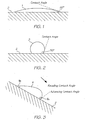
- FIG. 1 shows a droplet of liquid 1 having a contact angle of 20° on a solid surface 2. With acute contact angles, the liquid is said to be “mostly wetting” the surface 2.
- Figure 2 shows a droplet of another liquid 3 having a contact angle of 110° on the solid surface 2. With obtuse contact angles, the liquid is said to be “mostly non-wetting”.
- the contact angles shown in Figures 1 and 2 are static or equilibrium contact angles. Since the droplet is symmetrical, the contact angle measured on either side of the droplet would be the same. However, the situation changes if the droplet of liquid is moving.
- Figure 3 shows a droplet of liquid 4 moving down the surface 2, which is now sloped. As shown in Figure 3 , the shape of the droplet changes when it is moving. The result is that the contact angle on its leading (advancing) edge is greater than the contact on its tailing (receding) edge. In other words, the droplet is more wetting when receding and less wetting when advancing.
- the contact angle designated as ⁇ A in Figure 3 is called the Advancing Contact Angle
- ⁇ R in Figure 3 is called the Receding Contact Angle.
- the advancing contact angle is about 90°, whereas the receding contact angle is about 15°.
- this contact angle hysteresis is responsible for the cleaning action provided by the present invention.
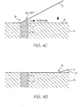
- a flexible pad 6 having a contact surface 7 is progressively brought into contact with a printhead 5 having an ink ejection face 8.
- Figure 4C shows an exploded view of a peel zone 9 in Figure 4B , when the contact surface 7 is partially in contact with the ink ejection face 8.
- Figure 4C shows in detail the behaviour of ink 11 as the surface 7 is contacted with a nozzle opening 10 on the printhead. Ink 11 in the nozzle opening 10 makes contact with the contact surface 7 as it advances across the printhead 5.
- the advancing contact angle ⁇ A of the ink 11 on the contact surface 7 is relatively non-wetting (about 90°), the ink has little or no tendency to wet onto the contact surface 7.
- the ink 11 remains on the ink ejection face 8 or in the nozzle 10, and the peel zone 9 advancing across the ink ejection face is relatively dry.
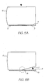
- FIGs 5A and 5B the reverse process is shown as the flexible pad 6 is peeled away from the ink ejection face 8.
- the contact surface 7 is sealingly engaged with the ink ejection face 8.
- the contact surface 7 is peeled away from the ink ejection face 8, and the peel zone 9 retreats across the face.
- Figure 5C shows a magnified view of the peel zone 9 as the contact surface 7 is peeled away from the nozzle opening 10 on the printhead 5.
- Ink 11 in the nozzle opening 10 makes contact with the contact surface 7 as it recedes across the ink ejection face 8.
- Figure 6 shows the flexible pad 6 as the last part of the contact surface 7 is peeled away from the ink ejection face 8.
- the contact surface 7 has collected a bead of ink 12 at the final point of contact with the printhead 5.
- the present invention may be implemented in many different forms, provided that the contact surface 7 is contacted with the ink ejection face 8 so as to produce a contact angle hysteresis.
- the contact surface 7 is contacted with the ink ejection face 8 so as to produce a contact angle hysteresis.
- a printhead maintenance station 20 comprises an elastically deformable pad 6 having a contact surface 7.
- the pad 6 is mounted on a support 23, having a recess 24 for receiving the pad.
- the support 23 is mounted on a support arm 25 having lugs 26 protruding from each end.
- the pad 21, support 23 and support arm 25 are bonded together to form a pad sub-assembly.
- a housing 30 comprises a body 31 and a cap 32, which is snap-fitted to the body with a plurality of snap-locks 33.
- the two-part construction of the housing 30 enables it to be assembled by receiving the pad sub-assembly in the body 31 and then snap-fitting the cap 32 onto the body.
- the lugs 26 protruding from each end of the support arm 25 are received in complementary slots 34 in the housing 30. Accordingly, the support arm 25 is slidably movable within the slots 34, allowing the pad 6 to move slidably relative to the housing 30.
- the extent of movement of the pad 6 is defined by the slots 34.
- the lugs 26 In a first position shown in Figure 7 , the lugs 26 abut an upper end 37 of each slot 34 and the pad 6 protrudes, at least partially, from the housing 30.
- the lugs 26 In a second position (not shown), the lugs 26 abut a lower end 38 of each slot 34, defined by the cap 32, and the pad 6 is withdrawn inside the housing 30.
- a pair of springs 35 are fixed to the cap 32 and urge against a lower surface 36 of the support arm 25.
- the springs 35 bias the pad 6 towards the first position shown in Figure 7 .
- the pad 6 is movable between the first and second positions by means of an engagement mechanism 40, which is shown in Figure 7 .
- the engagement mechanism 40 comprises a motor 41, which rotates a pair of cams 42, engaged with respective lugs 26 at each end of the support arm 25. Rotation of the motor 41 and the cam 42 causes linear sliding movement of the support arm 25 and, hence, the pad 6. Accordingly, the pad 6 may be moved reciprocally between the first and second positions upon actuation of the motor 41.
- the contact surface 7 In the first position, the contact surface 7 is sealingly engaged with the ink ejection face 8, as shown in detail in Figure 5A . In the second position, the contact surface 7, is disengaged from the ink ejection 8, as shown in Figure 4A . In between these two positions, the contact surface 7 may be either progressively contacting or peeling away from the ink ejection face 8.
- Figure 12 shows the perpendicular movement of the pad 6 with respect to the ink ejection face 8. As discussed above, this movement together with the profile of the contact surface 7 allows the printhead 5 to be maintained in an operable condition by sealing, cleaning and/or nozzle-clearing actions.
- the pad 6 is moved linearly and substantially perpendicularly with respect to the ink ejection face 8.
- the pad 6 is shown in Figures 4A and 12 having a sloped contact surface 7 in the form of a straight-line gradient. This sloped contact surface 7 allows it to be progressively contacted with and peeled away from the ink ejection face 8 during engagement and disengagement respectively.
- Figures 13 and 14 show two alternative configurations for the pad 6 in which the contact surface 7 has a curved profile in cross-section.
- the pad may alternatively be in the form of a cylinder 50, extending along the length of the printhead 5.
- the cylinder may be moved perpendicularly with respect to the ink ejection face 8 so that it is in either an engaged or a disengaged position.
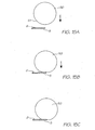
- Figures 15A-C show progressive contacting of a curved contact surface 51 of the cylinder 50 so that it is brought into sealing engagement with the ink ejection face 8. The reverse process of peeling the contact surface 51 away from the ink ejection face 8 cleans the face or clears blocked nozzles on the printhead 5, as described above.
- the cylinder 50 is offset from the printhead 5 so that any ink drawn from the printhead moves towards an edge portion of the printhead during disengagement, and not towards the centre.
- the contact surface 7 has been sloped. With a sloped contact surface 7, linear motion of the pad 6 produces the peeling action required by the invention.
- the pad 6 may be moved rotationally in order to achieve the progressive engagement and peeling disengagement from the ink ejection face 8.
- FIGS 16A-C there is shown a pad 60 mounted on an arm 61, which is attached to a pivot 62 at one end.
- the arm 61 is rotated by means of a motor 63 connected to the pivot 62.
- the pad 60 has a flat contact surface 64, which is progressively contacted with the ink ejection face 8 by virtue of the rotational movement of the arm 61.
- the pad 60 is peeled away from the ink ejection face 8 also by virtue of the rotational movement of the arm 61.
- the pad 60 may be cuboid-shaped in this alternative, since the requisite engagement and disengagement action is generated by the rotational movement of the pad.
- the pad is progressively contacted (and, by the reverse process, peeled away) along the longitudinal direction of the printhead 5.
- the printhead 5 has longitudinal rows of nozzles (not shown), with each row ejecting the same colored ink.
- color mixing between adjacent rows of nozzles is minimized as ink is drawn longitudinally along the ink ejection face 8 towards a transverse edge portion of the face and the pad 60.
- the pad may alternatively be in the form a roller 70, which extends along the length of the printhead 5.
- the roller 70 is rolled transversely across the ink ejection face 8 so that a leading peel zone 71 between the roller and the face is dry, and a tailing peel zone 72 between the roller and the face is wet.
- this difference is due to an advancing contact angle at the leading peel zone 71 being greater than a receding contact angle at the tailing peel zone 72.
- the rolling action has the effect of cleaning the ink ejection face 8 due to this contact angle hysteresis.
- advancing and receding contact angles are experienced simultaneously by different surfaces of the roller 70.
- the roller 70 is rolled across the ink ejection face using a rolling mechanism 73.
- the rolling mechanism 73 comprises a pivot arm 74 to which the roller 70 is rotatably mounted at one end.
- the pivot arm 74 is pivoted about a pivot 75, and an opposite end of the arm is moved by means of a solenoid 76. Actuation of the solenoid 76 causes the pivot arm 74 to pivot and the roller 70 is consequently rolled transversely across the ink ejection face 8.
- the cleaning action of the pad 6 generally deposits ink towards a predetermined region of the contact surface 7, which is typically an edge portion. Some ink may also be deposited on an edge portion of the ink ejection face 8 - either a transverse edge portion or a longitudinal edge portion depending on the configuration or movement of the pad 6.
- Figure 18 shows an embodiment where deposited ink 81 is removed by means of a wicking element 80 positioned adjacent a longitudinal edge 83 of the printhead 5.
- the wicking element 80 wicks ink away from a longitudinal edge portion 82 of the contact surface 7 and/or the ink ejection face 8. From Figure 18 , it can be seen that the edge portion 82 of the contact surface 7 extends past an edge of the printhead 5, allowing the edge portion 82 to contact with the wicking element 80 adjacent the printhead. Hence, ink deposited at the edge portion 82, as the contact surface 7 peels away from the ink ejection face 8, is transferred onto the wicking element 80.
- the edge portion 82 is the final point of contact between the contact surface 7 and the ink ejection face 8 during disengagement.
- the pad 6 and wicking element 80 are configured to move ink away from an opposite longitudinal edge portion 84 of the printhead 5, which comprises wirebond encapsulant 85.
- the encapsulant 85 protects wirebonds (not shown) connecting the printhead 5 to other printer components (not shown).
- the crowded environment around the printhead 5 means that the wirebonded edge portion 84 is relatively inaccessible. It is an advantage of the present invention that the pad 6 can access and move ink away from this severely crowded edge portion 84.
- the wicking element 80 is formed from an absorbent material, such as paper or foam, and is positioned in a cavity defined between a print media guide 86 and a support 87 on which the printhead 5 and print media guide are mounted.
- the print media guide 86 has a guide surface 88 for guiding print media past the printhead 5 when the pad 6 is fully disengaged from the ink ejection face 8.
- An ink collector 89 receives ink that has wicked through the wicking element 80, ensuring that ink is always removed away from the printhead 5.
- the wicking element 80 may become.damaged after repeated engagement of the pad 6.
- the wicking element 80 is comprised of paper and saturated with absorbed ink, it may disintegrate when contacted with the contact surface 7. Whilst more robust wicking materials may be used, a problem remains in that wicking rates through the material are relatively slow.
- a film 120 is positioned adjacent the longitudinal edge 83 of the printhead 5.
- the film 120 has a proximal longitudinal edge 121 and a distal longitudinal edge 122 relative to the printhead 5.
- the film 120 cooperates with the support 87 to define a wicking channel 124.
- the distal longitudinal edge 122 may be attached to the support 87 via a plurality of anchor points 123.
- the anchor points 123 may be, for example, spots of adhesive spaced apart along the distal edge 122.
- the distal edge 122 of the film 120 may be fixed to the paper guide 86, and the film held in position by being sandwiched between the support 87 and the paper guide.
- the film 120 is typically a biaxially oriented polyester film (e.g . Mylar ® film). Due to the stiffness and resilience of the film 120, attachment to the support 87 along the distal longitudinal edge 122 provides a tapered wicking channel 124. A channel inlet 125 is provided adjacent the longitudinal edge 83 of the printhead 5, while a channel outlet 126 is provided distal from the printhead 5.
- a biaxially oriented polyester film e.g . Mylar ® film
- ink received in the channel inlet 125 wicks rapidly along the channel towards the channel outlet 126 by capillary action, thereby removing ink away from the printhead 5. Furthermore, since the anchor points 123 are spaced apart along the distal longitudinal edge 122 of the film 120, ink can flow in between the anchor points and exit the channel outlet 126.
- a secondary wicking element 127 is positioned between the media guide 86 and the support 87 at the channel outlet 126.
- the secondary wicking element 87 is positioned to receive ink from the channel outlet 126 and wicks ink into the ink collector 89.
- the secondary wicking element 127 is comprised of an absorbent material, such as paper or foam. Since the secondary wicking element 127 is not physically contacted by the pad 6 during printhead maintenance operations, it has a comparatively long lifetime compared to the wicking element 80 described above.
- a plurality of vents in the form of slots 128 are defined in the film 120 towards its proximal longitudinal edge 121.
- the slots 128 are positioned for receiving any ink, which does not enter the channel inlet 125.
- any ink deposited on the outer surface of the film 120 i.e . the upper surface of the film 120 as shown in Figure 19
- the elongate slots 128, extending longitudinally along the film 120 have been shown to be particularly effective in wicking ink into the channel 124.
- any shape of vent may equally be used for the same purpose.
- FIG. 21 there is shown a printhead maintenance operation including cooperation of the contact surface 7 and the film 120.
- the pad 6 is fully engaged with the printhead 5.
- the edge portion 82 of the contact surface 7 abuts against the film 120, urging the film against the support 87.
- the edge portion 82 contacts the film 120 so that the vents 128 are sealed by the contact surface 7. In this way, any ink on the edge portion 82 of the contact surface 7 is squeezed into the vents 128 and into the channel 124, during engagement of the pad 6.
- the contact surface 7 has peeled away from the ink ejection face 8 so that ink 81 has moved towards the edge portions 82 and 83. Due to the resilience of the film 120 (and due, in part, to stiction forces between the film 120 and the contact surface 7), the tapered channel 124 is defined as the pad 6 is disengaged from the printhead 5. Accordingly, as shown in Figure 22 , the ink 81 removed from the ink ejection face 8 is positioned in the channel inlet 125 at the point of disengagement.
- the ink 81 Once the ink 81 has entered the channel inlet 125, it is rapidly wicked towards the channel outlet 126 due to the tapering of the channel 124 and the capillary action provided thereby. The ink 81 is subsequently received by the secondary wicking element 127 and deposited into the ink collector 89. Hence, efficient and rapid removal of ink 81 away from the contact surface 7 and/or printhead 5 is achieved.
- a wicking element 80 or film 120 may be positioned adjacent an edge portion 83 of the printhead 5, so that ink 81 is removed from the contact surface 7, ready for the next cleaning sequence.
- the maintenance station may be configured so that ink is removed from contact surface 7 after the pad 6 is disengaged from the printhead face 8.
- the engagement mechanism is configured to move the contact surface 7 into engagement with a remote cleaning means after it has disengaged from the printhead face 8.
- rotation of the pad 6 after disengagement may be used to bring the contact surface 7 into cleaning engagement with a squeegee or blotter.
- Rotation may, for example, rock the pad through an arc and past a squeegee.
- rotation may be fully through 180° using a similar mechanism to those used in rotating 'self-inking' stamps.
- Self-inking stamps have been known for decades in the stamping art (see, for example, US Patent Nos.
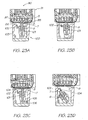
- Figures 23A-D show a cleaning sequence for a printhead assembly 90, in which the pad 6 is cleaned after disengagement from the printhead face 8 by rocking past a rubber squeegee.
- a printhead cartridge 91 comprising the printhead 5 mounted on support 92.
- Encapsulated wirebonds 85 extend from one longitudinal edge of the printhead 5, while the paper guide 88 is fixed to the support 87 on an opposite side of the printhead.
- a printhead maintenance station 100 comprising the pad 6 having the contact surface 7 for engagement with the ink ejection face 8 of the printhead 5.
- the pad is mounted on a cradle 101, which can be moved vertically towards the printhead 5 and which can also be rotated or rocked towards a rubber squeegee 102 fixed to a wall 103 of the maintenance station 100.
- the sloped contact surface 7 is brought into sealing engagement with the printhead face 8 by moving the pad 6 vertically upwards using an engagement mechanism (not shown) similar to that shown in Figures 7-11 .
- the printhead face 8 is cleaned by moving the pad 6 vertically downwards, thereby peeling the contact surface 7 away from the printhead face.
- a droplet of ink 104 is deposited along an edge portion of the contact surface 7 after it has disengaged from the printhead.
- the engagement mechanism moves the cradle 101 further downwards so that its bottom surface 105 abuts with a cam surface 106 on the maintenance station. Abutment of the cradle 101 with the cam surface 106 causes the cradle to rock towards the rubber squeegee 102.
- the squeegee 102 removes the ink droplet 104 from the contact surface 7 as it rocks past the squeegee. This cleans the pad ready for re-use in the next maintenance cycle.
- Any suitable cleaning means such as a foam pad, may of course be used to clean the pad 6 instead of the rubber squeegee 102 shown in Figures 19A-D .
- a biasing mechanism (not shown) rocks the cradle 101 back into its vertical position shown in Figure 23A as the cradle is moved upwards and away from the cam surface 106.
Landscapes
- Ink Jet (AREA)
- Printers Or Recording Devices Using Electromagnetic And Radiation Means (AREA)
- Types And Forms Of Lifts (AREA)
- Vehicle Body Suspensions (AREA)
- Earth Drilling (AREA)
- Electrical Discharge Machining, Electrochemical Machining, And Combined Machining (AREA)
Abstract
Description
- This invention relates to a maintenance assembly with a maintenance station for an inkjet printhead. It has been developed primarily for facilitating maintenance operations, such as sealing, cleaning or unblocking nozzles in an inkjet printhead.
- Inkjet printers are commonplace in homes and offices. More recently, inkjet printers have been proposed for use in portable devices, such as digital cameras, mobile phones etc. Furthermore, with the advent of MEMS technology, whereby inexpensive photolithographic techniques from the semiconductor industry are used to manufacture microelectomechanical systems, the possibility of disposable inkjet printers is becoming a commercial reality. The present Applicant has developed many different types of MEMS inkjet printheads, some of which are described in the patents and patent applications listed in the above cross reference list.
- Although the cost and power requirements of inkjet printheads is being reduced through the use of MEMS technology and improved inkjet nozzle designs, it is also necessary to reduce the cost and power requirements of other printer components, in order to incorporate inkjet printers into portable devices or to provide disposable inkjet printers.
- A crucial aspect of inkjet printing is maintaining the printhead in an operational printing condition throughout its lifetime. A number of factors may cause an inkjet printhead to become non-operational and it is important for any inkjet printer to include a strategy for preventing printhead failure and/or restoring the printhead to an operational printing condition in the event of failure. Printhead failure may be caused by, for example, printhead face flooding, dried-up nozzles (due to evaporation of water from the nozzles - a phenomenon known in the art as decap), or particulates fouling nozzles.
- In some cases, printhead failure may be remedied by simply firing nozzles periodically using a 'keep wet cycle'. This strategy does not require any external mechanical maintenance of the printhead and may be appropriate when a nozzle has not been fired for a relatively short period of time (e.g. less than 60 seconds). A 'keep wet cycle' can be used to address decap, and the consequent formation of viscous plugs in nozzles, during active printing.
- However, a 'keep wet cycle' cannot be used when the printer is left idle over long periods of time, for example, when it is in between print jobs, switched off or in transit. Furthermore, a 'keep wet cycle' is not appropriate for clearing severely blocked nozzles and does not address the problem of printhead face flooding. Accordingly, inkjet printers typically include a printhead maintenance station, which is designed to prevent printhead failure and/or remediate printheads to an operational condition.
- One measure that has been used for preventing printhead failure is sealing the printhead, thereby preventing evaporation of water and the drying up of nozzles. Commercial inkjet printers are typically supplied with a sealing tape across the printhead, which the user removes when the printer is installed for use. The sealing tape protects the primed printhead from particulates and prevents the nozzles from drying up during transit. Sealing tape also controls flooding of ink over the printhead face.
- Aside from one-time use sealing tape on new printers, sealing has also been used as a strategy for maintaining printheads in an operational condition during printing. In some commercial printers, a gasket-type sealing ring and cap engages around a perimeter of the printhead when the printer is idle. With the printhead capped in this way, evaporation of water from the nozzles is minimized, and a relatively humid atmosphere can be maintained above the nozzles, thereby minimizing the extent to which nozzles dry up.
- Furthermore, gasket-type sealing rings have been combined with suction cleaning in prior art maintenance stations. A vacuum may be connected to the sealing cap and used to suck ink from the nozzles. The sealing cap minimizes nozzle drying and entrance of particulates from the atmosphere, while the suction ensures any blocked nozzles are cleared prior to printing. Hence, this type of maintenance station employs both preventative and remedial measures.
- Another remedial strategy used in prior art printhead maintenance stations is a rubber squeegee. The squeegee does not act as seal; rather, it is wiped across the printhead and removes any flooded ink. Squeegee cleaning may be used immediately prior to printing, after the vacuum flush described above.
- The printhead maintenance strategies described above have several shortcomings, especially in the present age of inkjet printing. Modern inkjet printers are required to have smaller drop volumes, and hence smaller nozzle openings, for high resolution photographic printing. It is also desirable to use stationary pagewidth printheads for high-speed printing, as opposed to scanning printheads. It is also desirable to reduce the overall cost of inkjet printers and incorporate them into low-powered portable devices, such as digital cameras and mobile phones.
- Current printhead maintenance strategies are unable to provide inkjet printers, which meet these demands. With smaller nozzle openings (of the order of 5-20 microns), nozzle blocking due to decap becomes a serious problem. At present, the only reliable way of dealing with blocked nozzles is to use a suction pad. However, suction devices are bulky, expensive and consume large amounts of power, making them unsuitable for many inkjet applications. Furthermore, suction pads are wasteful of ink and can consume up to 0.25 ml of ink with each remediation.
- Additionally, none of the prior art maintenance stations are able to provide a printhead ready for printing after a single maintenance operation. Typically, it is necessary to employ separate preventative (e.g. sealing) and remedial (e.g. suction and squeegee-cleaning) measures in order to provide a fully operational printhead. However, operations such as squeegee-cleaning are not suitable for all types of printhead, because it exerts shear stress across the printhead and can damage sensitive nozzle structures.
-
US 4,571,601 describes a printhead maintenance assembly comprising a silicone roller, which engages with an ink ejection face of a printhead. Whilst the roller is engaged with the printhead, the roller is rotated so as to remove impurities from the ink ejection face. -
US 2004/125167 A1 discloses an inkjet printer with a printhead assembly for maintaining a printhead in an operable condition. Said printhead assembly consists of a printhead having an ink ejection face with nozzles and a printhead maintenance station. The maintenance station comprises an elastically deformable pad having a contact surface configured for sealing engagement with some of the nozzles of the ink ejection face and an engagement mechanism for rolling said pad across the ejection face between a first position in which said contact surface is sealingly engaged with nozzles, and a second position in which said contact surface is disengaged, whereby said contact surface is progressively contacted with said nozzles during sealing engagement and peeled away from said nozzles during disengagement. - Therefore, it would be desirable to provide an inkjet printhead maintenance station, which combines both preventative and remedial measures. It would further be desirable to provide an inkjet printhead maintenance station, which can be fabricated at low cost and is therefore suitable for fabrication of a disposable printer. It would be further desirable to provide an inkjet printhead maintenance station, which does not significantly impact on the overall size of the printer and is therefore suitable for incorporation into handheld electronic devices. It would be further desirable to provide an inkjet printhead maintenance station, which does not impact on the overall power consumption of the printer and is therefore suitable for incorporation into battery-powered electronic devices. It would be further desirable to provide an inkjet printhead maintenance station, which does not waste large quantities of ink with each remedial operation. It would further be desirable to provide an inkjet printhead maintenance station, which cleans ink from a flooded printhead without exerting high shear stresses across the printhead.
- Accordingly, a first embodiment of the invention provides a printhead assembly as detailed in
claim 1. The invention also provides an ink jet printer as detailed inclaim 11. Advantageous embodiments are provided in the dependent claims. - For the avoidance of doubt, the term "progressively contacted" is used to mean a type of engagement, which is opposite to "peeling away". In other words, different portions of the contact surface progressively come into contact with the ink ejection face at different times during engagement. Likewise, different portions of the contact surface are progressively peeled away from the ink ejection face at different times during disengagement. The specification and drawings below describe in detail this type of engagement and disengagement, and various ways of achieving such engagement and disengagement.
- The printhead maintenance station advantageously combines both preventative and remedial measures for maintaining an inkjet printhead in an operable condition. In terms of preventative measures, the contact surface seals the ink ejection face, thereby minimizing evaporation of water from the nozzles and minimizing the effects of ink drying up inside the nozzles. Sealing engagement of the contact surface with the ink ejection face also protects the printhead from particulates in the atmosphere, which can damage or block nozzles. Typically, the pad is held in its first position when the printhead is left idle over relatively long periods. However, the pad may be moved into sealing engagement at any time when the printhead is not printing.
- In terms of remedial measures, the contact surface cleans ink from the ink ejection face due to the unique interaction between the contact surface and the printhead. From a detailed analysis of advancing and receding contact angles, the present inventors have found that peeling disengagement of the contact surface from the ink ejection face has the effect of moving ink along the contact surface (or the ink ejection face) towards an edge portion. Once deposited at an edge portion, the ink may be readily removed. A detailed explanation of the principle of advancing and receding contact angles, and how these relate to the present invention is given below.
- In addition to cleaning flooded ink from the ink ejection face, the peeling disengagement action of the contact surface from the printhead also has the effect of unblocking nozzles. Peeling disengagement generates a negative pressure above nozzles in the printhead and, hence, draws out viscous ink material or particulate contaminants blocking the nozzles. Accordingly, the peeling disengagement has the combined effects of clearing blocked nozzles and removing ink to an edge portion of the contact surface or printhead.
- A further advantage of the printhead maintenance station is that it has a simple design, which is compact, can be manufactured at low cost and consumes very little power. The suction devices of the prior art require external pumps, which add significantly to the cost and power consumption of prior art printers. Moreover, the requirement of an external vacuum pump adds significantly to the bulk of prior art printers. By obviating the need for a vacuum pump to effectively unblock printhead nozzles, the present invention allows inkjet printers to be installed into a wider range of devices and also opens up the potential for a commercially-viable disposable inkjet printer.
- A further advantage of the printhead maintenance station is that nozzles can be unblocked without wasting large quantities of ink. Whereas prior art suction devices are wasteful of ink, adding to the overall cost of printer operation, the present invention withdraws only a minimum quantity of ink from nozzles during remediation. Moreover, by depositing the ink onto an edge portion of the pad (and/or the printhead), the means for removing this ink is greatly simplified.
- A further advantage of the printhead maintenance station is that the cleaning action exerts minimal shear stress across the ink ejection face. Accordingly, sensitive nozzle structures are less likely to be damaged during maintenance when compared to, for example, wiping or squeegee cleaning of printheads.
- Optionally, the pad is substantially coextensive with the printhead. A pad configured in this way ensures maintenance of the entire printhead, whilst simplifying the design of the maintenance station as far as possible. As described below a portion of the pad may extend beyond one end of the printhead, although this type of arrangement is still understood to be within the definition of the term 'substantially coextensive'.
- The contact surface is substantially uniform, so that ink can flow freely across its surface. Optionally, the contact surface should have a minimal number of pits or indentations, to avoid trapping ink in micro-pockets and consequently reducing the efficacy of the cleaning action.
- The pad is elastically deformable and, preferably, has minimal or no creep. Elastic deformability provides sealing engagement of the pad with the printhead. Moreover, it ensures the pad can be used repeatedly without loss of either sealing or cleaning performance. Suitable materials for forming the pad include thermosetting or thermoplastic elastomers. For example, the pad may be comprised of silicone, polyurethane, Neoprene®, Santoprene® or Kraton®. Optionally, the pad is comprised of a silicone rubber.
- Optionally a peel zone between the contact surface and the ink ejection face advances and retreats transversely across the ink ejection face during engagement and disengagement. In this embodiment, ink retreats with the peel zone in a longitudinal line towards a longitudinal edge portion of the contact surface or printhead as the pad is peeled away. This has the advantage that the ink travels a minimum distance across the ink ejection face and maximizes the cleaning efficiency of the maintenance station.
- The engagement mechanism moves the pad substantially perpendicularly with respect to the ink ejection face. This arrangement has the advantage of simplifying the motion of the pad and, moreover, the means for achieving this. For example, a simple solenoid or motor/cam arrangement, consuming very little power, may be used to provide reciprocal linear movement of the pad.
- With the pad being moved perpendicularly with respect to the ink ejection face, the unique engagement action of the contact surface is usually determined by the profile of the contact surface itself. Optionally, the pad is configured so that the contact surface is sloped with respect to the ink ejection face. Accordingly, during perpendicular engagement of the pad with the ink ejection face, a first end of the contact surface is contacted before a second end of the contact surface. Sloping of the contact surface may be in the form of a linear gradient (i.e. the contact surface is flat). For example, the contact surface may be angled at 5-30°, 8-20° or 10-15° with respect to the ink ejection face. Alternatively, sloping of the contact surface may be in the form of a curved or rounded gradient. In either case, progressive contact of the surface with the ink ejection face is ensured during engagement. Likewise, a peeling motion is ensured during disengagement.
- As mentioned above, engagement of the pad may be provided so as to engage the contact surface progressively transversely across the printhead.
- The maintenance station is typically configured so that peeling disengagement of the contact surface from the ink ejection face draws ink from the printhead towards an edge portion of the contact surface, the ink ejection face, or both. This cleaning action may be used to clear blocked nozzles and remove ink flooded on the surface of the ink ejection face.
- The speed of engagement and disengagement, together with the contact time, may be varied in order to optimize the cleaning action. Optimal cleaning will also depend on other factors, such as the size of printhead, the elasticity of the pad, the shape of the pad, the motion of the engagement mechanism etc. The skilled person will readily be able to optimize cleaning of the printhead for any given system by varying one or more of these parameters.
- The pad may be moved according to a predetermined algorithm, depending on the expected severity of nozzle blockage. For example, different maintenance actions may be suitable for different printer conditions (e.g. first use, paper jam, recovery, user intervention etc.). Some situations may require five reciprocal movements of the pad, whereas other situations may require only one engage/disengage sequence. Suitable algorithms may be programmed into a control system controlling operation of the printhead maintenance station.
- Optionally, the maintenance station further comprises an ink removal system for removing ink deposited on an edge portion of the contact surface or ink ejection face. The ink removal system advantageously avoids build up of ink on the pad or on the printhead, and channels any surplus ink away from the printhead.
- The ink removal system may comprise any substrate or mechanism that can effectively remove ink from the edge portion(s). For example, the pad may be moved and contacted with an absorbent material after it has disengaged from the printhead.
- Optionally, the ink removal system comprises a wicking element positioned adjacent an edge of the printhead. Ink which has been deposited towards the edge of the printhead and the pad is absorbed into the wicking element, which may simply be an absorbent material, and removed by wicking through the material. This arrangement has the advantage of simplicity and obviates the need for additional moving parts or a vacuum system in the maintenance station.
- Optionally, the ink removal system comprises a wicking channel.
- The invention has been developed primarily for use with a pagewidth inkjet printhead. Optionally, the printhead comprises a plurality of nozzles, with each nozzle having a diameter of less than 20 microns or less than 15 microns.
- However, the invention is equally applicable to any type of printhead where sealing and/or remedial measures are required to maintain the printhead in an operable condition. For example, the invention may be used in connection with standard scanning inkjet printheads in order to simplify conventional maintenance stations.
- Specific forms of the present invention will be now be described in detail, with reference to the following drawings, in which:-
-
Figure 1 shows an equilibrium contact angle for a wetting droplet of liquid on a surface; -
Figure 2 shows an equilibrium contact angle for a non-wetting droplet of liquid on a surface; -
Figure 3 shows advancing and receding contact angles for a droplet of liquid moving along a surface; -
Figure 4A is a side view of a contact surface before engagement with an ink ejection face of a printhead; -
Figure 4B is a side view of a contact surface partially engaged with the ink ejection face during engagement; -
Figure 4C shows in detail a peel zone between the contact surface and a printhead nozzle during engagement; -
Figure 4D shows in detail the peel zone inFigure 4C after it has advanced past the nozzle; -
Figure 5A is a side view of the contact surface sealingly engaged with the ink ejection face; -
Figure 5B is a side view of a contact surface partially engaged with the ink ejection face during disengagement; -
Figure 5C shows in detail a peel zone between the contact surface and a printhead nozzle during disengagement; -
Figure 5D shows in detail the peel zone inFigure 4C as it retreats from the nozzle; -
Figure 5E shows in detail the peel zone inFigure 4D after it has retreated from the nozzle; -
Figure 6 is a side view of the contact surface immediately after it has disengaged from the ink ejection face; -
Figure 7 is a longitudinal side section view through a printhead maintenance station according to the invention; -
Figure 8 is a side view of the printhead maintenance station shown inFigure 7 ; -
Figure 9 is a transverse side section view of the printhead maintenance station shown inFigure 7 ; -
Figure 10 is an end view of the printhead maintenance station shown inFigure 7 ; -
Figure 11 is an exploded perspective view of the printhead maintenance station shown inFigure 7 ; -
Figure 12 is a perspective view of a pad moving perpendicularly with respect to an ink ejection face of a printhead; -
Figure 13 is a perspective view of a pad; -
Figure 14 is a perspective view of a pad; -
Figure 15A-C are schematic side views of a cylindrical pad at various stages of engagement with an ink ejection face of a printhead; -
Figure 16A-C are schematic side views of a contact surface being brought into engagement with an ink ejection face of a printhead by rotational movement; -
Figure 17 is a schematic side view of a roller being rolled across an ink ejection face of a printhead; -
Figure 18 is a schematic side view of a printhead assembly comprising a wicking element; -
Figure 19 is a schematic side view of a printhead assembly comprising a wicking channel; -
Figure 20 is a plan view of the printhead and film shown inFigure 19 ; -
Figure 21 is a schematic side view of the printhead assembly shown inFigure 19 with the pad fully engaged; -
Figure 22 is a schematic side view of the printhead assembly shown inFigure 21 at the point of disengagement; and -
Figures 23A-D are transverse side section views of a printhead maintenance station, having a rotating pad cleaning action, in various stages of a printhead maintenance cycle. - In general terms, and as mentioned above, the present invention relies on an understanding of contact angles - specifically, a hysteresis between advancing and receding contact angles.
- The shape of a droplet of liquid on a solid surface is determined by its contact angle(s). Depending on factors such as the surface tension in the liquid and the interactive forces between the solid and the liquid, the shape of the droplet will change.
Figure 1 shows a droplet ofliquid 1 having a contact angle of 20° on asolid surface 2. With acute contact angles, the liquid is said to be "mostly wetting" thesurface 2.Figure 2 shows a droplet of anotherliquid 3 having a contact angle of 110° on thesolid surface 2. With obtuse contact angles, the liquid is said to be "mostly non-wetting". - The contact angles shown in
Figures 1 and 2 are static or equilibrium contact angles. Since the droplet is symmetrical, the contact angle measured on either side of the droplet would be the same. However, the situation changes if the droplet of liquid is moving.Figure 3 shows a droplet ofliquid 4 moving down thesurface 2, which is now sloped. As shown inFigure 3 , the shape of the droplet changes when it is moving. The result is that the contact angle on its leading (advancing) edge is greater than the contact on its tailing (receding) edge. In other words, the droplet is more wetting when receding and less wetting when advancing. The contact angle designated as θA inFigure 3 is called the Advancing Contact Angle, and the contact angle designated as θR inFigure 3 is called the Receding Contact Angle. - For a typical droplet of ink moving across a silicone surface, the advancing contact angle is about 90°, whereas the receding contact angle is about 15°. Without wishing to be bound by theory, it is understood by the present inventors that this contact angle hysteresis is responsible for the cleaning action provided by the present invention.
- In
Figures 4A and 4B , aflexible pad 6 having acontact surface 7 is progressively brought into contact with aprinthead 5 having anink ejection face 8.Figure 4C shows an exploded view of apeel zone 9 inFigure 4B , when thecontact surface 7 is partially in contact with theink ejection face 8.Figure 4C shows in detail the behaviour ofink 11 as thesurface 7 is contacted with anozzle opening 10 on the printhead.Ink 11 in thenozzle opening 10 makes contact with thecontact surface 7 as it advances across theprinthead 5. However, since the advancing contact angle θA of theink 11 on thecontact surface 7 is relatively non-wetting (about 90°), the ink has little or no tendency to wet onto thecontact surface 7. Hence, as shown inFigure 4D , theink 11 remains on theink ejection face 8 or in thenozzle 10, and thepeel zone 9 advancing across the ink ejection face is relatively dry. - In
Figures 5A and 5B , the reverse process is shown as theflexible pad 6 is peeled away from theink ejection face 8. Initially, as shown inFigure 5A , thecontact surface 7 is sealingly engaged with theink ejection face 8. InFigure 5B , thecontact surface 7 is peeled away from theink ejection face 8, and thepeel zone 9 retreats across the face.Figure 5C shows a magnified view of thepeel zone 9 as thecontact surface 7 is peeled away from thenozzle opening 10 on theprinthead 5.Ink 11 in thenozzle opening 10 makes contact with thecontact surface 7 as it recedes across theink ejection face 8. However, since the receding contact angle θR of theink 11 on thesurface 7 is relatively wetting (about 15°), the ink in thenozzle opening 10 now tends to wet onto thecontact surface 7. Hence, as shown inFigures 5D and 5E , thepeel zone 9 retreating across theink ejection face 8 is wet, carrying with it a droplet ofink 12 drawn from thenozzle opening 10 or from theink ejection face 8. This has the effect of clearing blocked nozzles in theprinthead 5 and cleaning ink flooded on theink ejection face 8. -
Figure 6 shows theflexible pad 6 as the last part of thecontact surface 7 is peeled away from theink ejection face 8. Thecontact surface 7 has collected a bead ofink 12 at the final point of contact with theprinthead 5. - As will be readily appreciated from the foregoing discussion, the present invention may be implemented in many different forms, provided that the
contact surface 7 is contacted with theink ejection face 8 so as to produce a contact angle hysteresis. Various forms of the invention are described in detail below. - Referring to
Figures 7 to 11 , aprinthead maintenance station 20 comprises an elasticallydeformable pad 6 having acontact surface 7. Thepad 6 is mounted on asupport 23, having arecess 24 for receiving the pad. Thesupport 23 is mounted on asupport arm 25 havinglugs 26 protruding from each end. The pad 21,support 23 andsupport arm 25 are bonded together to form a pad sub-assembly. - A
housing 30 comprises abody 31 and acap 32, which is snap-fitted to the body with a plurality of snap-locks 33. The two-part construction of thehousing 30 enables it to be assembled by receiving the pad sub-assembly in thebody 31 and then snap-fitting thecap 32 onto the body. Thelugs 26 protruding from each end of thesupport arm 25 are received incomplementary slots 34 in thehousing 30. Accordingly, thesupport arm 25 is slidably movable within theslots 34, allowing thepad 6 to move slidably relative to thehousing 30. - The extent of movement of the
pad 6 is defined by theslots 34. In a first position shown inFigure 7 , thelugs 26 abut anupper end 37 of eachslot 34 and thepad 6 protrudes, at least partially, from thehousing 30. In a second position (not shown), thelugs 26 abut alower end 38 of eachslot 34, defined by thecap 32, and thepad 6 is withdrawn inside thehousing 30. - As shown in
Figure 11 , a pair ofsprings 35 are fixed to thecap 32 and urge against alower surface 36 of thesupport arm 25. Thesprings 35 bias thepad 6 towards the first position shown inFigure 7 . - The
pad 6 is movable between the first and second positions by means of anengagement mechanism 40, which is shown inFigure 7 . Theengagement mechanism 40 comprises amotor 41, which rotates a pair ofcams 42, engaged withrespective lugs 26 at each end of thesupport arm 25. Rotation of themotor 41 and thecam 42 causes linear sliding movement of thesupport arm 25 and, hence, thepad 6. Accordingly, thepad 6 may be moved reciprocally between the first and second positions upon actuation of themotor 41. - In the first position, the
contact surface 7 is sealingly engaged with theink ejection face 8, as shown in detail inFigure 5A . In the second position, thecontact surface 7, is disengaged from theink ejection 8, as shown inFigure 4A . In between these two positions, thecontact surface 7 may be either progressively contacting or peeling away from theink ejection face 8. -
Figure 12 shows the perpendicular movement of thepad 6 with respect to theink ejection face 8. As discussed above, this movement together with the profile of thecontact surface 7 allows theprinthead 5 to be maintained in an operable condition by sealing, cleaning and/or nozzle-clearing actions. - In the embodiment shown in
Figures 4-12 , thepad 6 is moved linearly and substantially perpendicularly with respect to theink ejection face 8. Thepad 6 is shown inFigures 4A and12 having a slopedcontact surface 7 in the form of a straight-line gradient. Thissloped contact surface 7 allows it to be progressively contacted with and peeled away from theink ejection face 8 during engagement and disengagement respectively. - However, the contact surface may adopt other profiles and still achieve a similar effect when moved perpendicularly with respect to the
ink ejection face 8.Figures 13 and 14 show two alternative configurations for thepad 6 in which thecontact surface 7 has a curved profile in cross-section. - As shown in
Figures 15A-C , the pad may alternatively be in the form of acylinder 50, extending along the length of theprinthead 5. The cylinder may be moved perpendicularly with respect to theink ejection face 8 so that it is in either an engaged or a disengaged position.Figures 15A-C show progressive contacting of acurved contact surface 51 of thecylinder 50 so that it is brought into sealing engagement with theink ejection face 8. The reverse process of peeling thecontact surface 51 away from theink ejection face 8 cleans the face or clears blocked nozzles on theprinthead 5, as described above. Thecylinder 50 is offset from theprinthead 5 so that any ink drawn from the printhead moves towards an edge portion of the printhead during disengagement, and not towards the centre. - Any of these alternative pads may readily be incorporated into the
printhead maintenance station 20 described above by simple replacement of thepad 6 inFigure 11 . - In all the embodiments described thus far, the
contact surface 7 has been sloped. With a slopedcontact surface 7, linear motion of thepad 6 produces the peeling action required by the invention. However, as an alternative not falling under the subject-matter of the claims, thepad 6 may be moved rotationally in order to achieve the progressive engagement and peeling disengagement from theink ejection face 8. - In
Figures 16A-C , there is shown apad 60 mounted on anarm 61, which is attached to apivot 62 at one end. Thearm 61 is rotated by means of amotor 63 connected to thepivot 62. Thepad 60 has aflat contact surface 64, which is progressively contacted with theink ejection face 8 by virtue of the rotational movement of thearm 61. In the reverse process (not shown), thepad 60 is peeled away from theink ejection face 8 also by virtue of the rotational movement of thearm 61. Thepad 60 may be cuboid-shaped in this alternative, since the requisite engagement and disengagement action is generated by the rotational movement of the pad. - As shown in
Figures 16A-C , the pad is progressively contacted (and, by the reverse process, peeled away) along the longitudinal direction of theprinthead 5. Theprinthead 5 has longitudinal rows of nozzles (not shown), with each row ejecting the same colored ink. By engaging/disengaging thepad 60 along the longitudinal direction of theprinthead 5, color mixing between adjacent rows of nozzles is minimized as ink is drawn longitudinally along theink ejection face 8 towards a transverse edge portion of the face and thepad 60. - As an alternative not falling under the subject- matter of the claims as shown in
Figure 17 , the pad may alternatively be in the form aroller 70, which extends along the length of theprinthead 5. In this alternative embodiment, theroller 70 is rolled transversely across theink ejection face 8 so that a leadingpeel zone 71 between the roller and the face is dry, and a tailingpeel zone 72 between the roller and the face is wet. As explained above, this difference is due to an advancing contact angle at the leadingpeel zone 71 being greater than a receding contact angle at the tailingpeel zone 72. Accordingly, the rolling action has the effect of cleaning theink ejection face 8 due to this contact angle hysteresis. Unlike the embodiments described above, in this alternative, advancing and receding contact angles are experienced simultaneously by different surfaces of theroller 70. - The
roller 70 is rolled across the ink ejection face using arolling mechanism 73. The rollingmechanism 73 comprises apivot arm 74 to which theroller 70 is rotatably mounted at one end. Thepivot arm 74 is pivoted about apivot 75, and an opposite end of the arm is moved by means of asolenoid 76. Actuation of thesolenoid 76 causes thepivot arm 74 to pivot and theroller 70 is consequently rolled transversely across theink ejection face 8. - In all the embodiments and alternative not falling under the subject-matter of the claims as and alternative described above, the cleaning action of the
pad 6 generally deposits ink towards a predetermined region of thecontact surface 7, which is typically an edge portion. Some ink may also be deposited on an edge portion of the ink ejection face 8 - either a transverse edge portion or a longitudinal edge portion depending on the configuration or movement of thepad 6. -
Figure 18 shows an embodiment where depositedink 81 is removed by means of a wicking element 80 positioned adjacent alongitudinal edge 83 of theprinthead 5. The wicking element 80 wicks ink away from alongitudinal edge portion 82 of thecontact surface 7 and/or theink ejection face 8. FromFigure 18 , it can be seen that theedge portion 82 of thecontact surface 7 extends past an edge of theprinthead 5, allowing theedge portion 82 to contact with the wicking element 80 adjacent the printhead. Hence, ink deposited at theedge portion 82, as thecontact surface 7 peels away from theink ejection face 8, is transferred onto the wicking element 80. Theedge portion 82 is the final point of contact between thecontact surface 7 and theink ejection face 8 during disengagement. - The
pad 6 and wicking element 80 are configured to move ink away from an oppositelongitudinal edge portion 84 of theprinthead 5, which compriseswirebond encapsulant 85. Theencapsulant 85 protects wirebonds (not shown) connecting theprinthead 5 to other printer components (not shown). - The crowded environment around the
printhead 5 means that thewirebonded edge portion 84 is relatively inaccessible. It is an advantage of the present invention that thepad 6 can access and move ink away from this severelycrowded edge portion 84. - The wicking element 80 is formed from an absorbent material, such as paper or foam, and is positioned in a cavity defined between a print media guide 86 and a
support 87 on which theprinthead 5 and print media guide are mounted. The print media guide 86 has aguide surface 88 for guiding print media past theprinthead 5 when thepad 6 is fully disengaged from theink ejection face 8. - An
ink collector 89 receives ink that has wicked through the wicking element 80, ensuring that ink is always removed away from theprinthead 5. - With repeated maintenance operations, the wicking element 80 may become.damaged after repeated engagement of the
pad 6. In particular, if the wicking element 80 is comprised of paper and saturated with absorbed ink, it may disintegrate when contacted with thecontact surface 7. Whilst more robust wicking materials may be used, a problem remains in that wicking rates through the material are relatively slow. - In an example, and referring to
Figures 19 and 20 , afilm 120 is positioned adjacent thelongitudinal edge 83 of theprinthead 5. Thefilm 120 has a proximallongitudinal edge 121 and a distallongitudinal edge 122 relative to theprinthead 5. Thefilm 120 cooperates with thesupport 87 to define awicking channel 124. The distallongitudinal edge 122 may be attached to thesupport 87 via a plurality of anchor points 123. The anchor points 123 may be, for example, spots of adhesive spaced apart along thedistal edge 122. Alternatively, thedistal edge 122 of thefilm 120 may be fixed to thepaper guide 86, and the film held in position by being sandwiched between thesupport 87 and the paper guide. - The
film 120 is typically a biaxially oriented polyester film (e.g. Mylar® film). Due to the stiffness and resilience of thefilm 120, attachment to thesupport 87 along the distallongitudinal edge 122 provides atapered wicking channel 124. Achannel inlet 125 is provided adjacent thelongitudinal edge 83 of theprinthead 5, while achannel outlet 126 is provided distal from theprinthead 5. - Due to the tapering of the
wicking channel 124, ink received in thechannel inlet 125 wicks rapidly along the channel towards thechannel outlet 126 by capillary action, thereby removing ink away from theprinthead 5. Furthermore, since the anchor points 123 are spaced apart along the distallongitudinal edge 122 of thefilm 120, ink can flow in between the anchor points and exit thechannel outlet 126. - A
secondary wicking element 127 is positioned between the media guide 86 and thesupport 87 at thechannel outlet 126. Thesecondary wicking element 87 is positioned to receive ink from thechannel outlet 126 and wicks ink into theink collector 89. Thesecondary wicking element 127 is comprised of an absorbent material, such as paper or foam. Since thesecondary wicking element 127 is not physically contacted by thepad 6 during printhead maintenance operations, it has a comparatively long lifetime compared to the wicking element 80 described above. - Referring to
Figure 20 , a plurality of vents in the form ofslots 128 are defined in thefilm 120 towards its proximallongitudinal edge 121. Theslots 128 are positioned for receiving any ink, which does not enter thechannel inlet 125. For example, any ink deposited on the outer surface of the film 120 (i.e. the upper surface of thefilm 120 as shown inFigure 19 ) during printhead maintenance, is wicked into thechannel 124 via theslots 128. Theelongate slots 128, extending longitudinally along thefilm 120, have been shown to be particularly effective in wicking ink into thechannel 124. However, any shape of vent may equally be used for the same purpose. - Referring to
Figures 21 and 22 , there is shown a printhead maintenance operation including cooperation of thecontact surface 7 and thefilm 120. InFigure 21 , thepad 6 is fully engaged with theprinthead 5. Theedge portion 82 of thecontact surface 7 abuts against thefilm 120, urging the film against thesupport 87. Theedge portion 82 contacts thefilm 120 so that thevents 128 are sealed by thecontact surface 7. In this way, any ink on theedge portion 82 of thecontact surface 7 is squeezed into thevents 128 and into thechannel 124, during engagement of thepad 6. - In
Figure 22 , thecontact surface 7 has peeled away from theink ejection face 8 so thatink 81 has moved towards theedge portions film 120 and the contact surface 7), the taperedchannel 124 is defined as thepad 6 is disengaged from theprinthead 5. Accordingly, as shown inFigure 22 , theink 81 removed from theink ejection face 8 is positioned in thechannel inlet 125 at the point of disengagement. - Once the
ink 81 has entered thechannel inlet 125, it is rapidly wicked towards thechannel outlet 126 due to the tapering of thechannel 124 and the capillary action provided thereby. Theink 81 is subsequently received by thesecondary wicking element 127 and deposited into theink collector 89. Hence, efficient and rapid removal ofink 81 away from thecontact surface 7 and/orprinthead 5 is achieved. - As described above, a wicking element 80 or
film 120 may be positioned adjacent anedge portion 83 of theprinthead 5, so thatink 81 is removed from thecontact surface 7, ready for the next cleaning sequence. - In an example, the maintenance station may be configured so that ink is removed from
contact surface 7 after thepad 6 is disengaged from theprinthead face 8. In this example, the engagement mechanism is configured to move thecontact surface 7 into engagement with a remote cleaning means after it has disengaged from theprinthead face 8. For example, rotation of thepad 6 after disengagement may be used to bring thecontact surface 7 into cleaning engagement with a squeegee or blotter. Rotation may, for example, rock the pad through an arc and past a squeegee. Alternatively, rotation may be fully through 180° using a similar mechanism to those used in rotating 'self-inking' stamps. Self-inking stamps have been known for decades in the stamping art (see, for example,US Patent Nos. 239,779 ;405,704 ;669,137 ;827,347 ;1,121,940 ;2,079,080 ;2,312,727 ;2,919,645 ;3,364,856 ;3,402,663 ;3,631,799 ;3,952,653 ;3,988,987 ;4,432,281 and4,852,489 ), and the skilled person will readily appreciate how such stamping mechanisms may be used to rotate thepad 6 through 180° onto a blotter after it has disengaged from theprinthead face 8. -
Figures 23A-D show a cleaning sequence for aprinthead assembly 90, in which thepad 6 is cleaned after disengagement from theprinthead face 8 by rocking past a rubber squeegee. - Referring to
Figure 23A , there is shown in cross-section aprinthead cartridge 91 comprising theprinthead 5 mounted on support 92. Encapsulated wirebonds 85 extend from one longitudinal edge of theprinthead 5, while thepaper guide 88 is fixed to thesupport 87 on an opposite side of the printhead. Still referring toFigure 23A , there is also shown a printhead maintenance station 100 comprising thepad 6 having thecontact surface 7 for engagement with theink ejection face 8 of theprinthead 5. The pad is mounted on acradle 101, which can be moved vertically towards theprinthead 5 and which can also be rotated or rocked towards arubber squeegee 102 fixed to awall 103 of the maintenance station 100. - Referring now to
Figure 23B , the slopedcontact surface 7 is brought into sealing engagement with theprinthead face 8 by moving thepad 6 vertically upwards using an engagement mechanism (not shown) similar to that shown inFigures 7-11 . - In
Figure 23C , theprinthead face 8 is cleaned by moving thepad 6 vertically downwards, thereby peeling thecontact surface 7 away from the printhead face. A droplet ofink 104 is deposited along an edge portion of thecontact surface 7 after it has disengaged from the printhead. - In
Figure 23D , the engagement mechanism (not shown) moves thecradle 101 further downwards so that itsbottom surface 105 abuts with a cam surface 106 on the maintenance station. Abutment of thecradle 101 with the cam surface 106 causes the cradle to rock towards therubber squeegee 102. Thesqueegee 102 removes theink droplet 104 from thecontact surface 7 as it rocks past the squeegee. This cleans the pad ready for re-use in the next maintenance cycle. Any suitable cleaning means, such as a foam pad, may of course be used to clean thepad 6 instead of therubber squeegee 102 shown inFigures 19A-D . - Finally, the
cradle 101 is moved back into the position shown inFigure 23A , which completes the maintenance cycle. A biasing mechanism (not shown) rocks thecradle 101 back into its vertical position shown inFigure 23A as the cradle is moved upwards and away from the cam surface 106. - It will, of course, be appreciated that the present invention has been described purely by way of example and that modifications of detail may be made within the scope of the invention, which is defined by the accompanying claims.
Claims (9)
- A printhead assembly for maintaining a printhead in an operable condition, said printhead maintenance assembly comprising:a printhead (5) comprising an ink ejection face (8) having nozzles (10) for ejection of ink (11); anda printhead maintenance station (20) comprising:an elastically deformable pad (6) having a substantially uniform contact surface (7) configured for sealing engagement with all the nozzles (10) contained in the ink ejection face (8) of the printhead (5); andan engagement mechanism for moving said pad substantially perpendicularly with respect to said ink ejection face between a first position in which said contact surface (7) is sealingly engaged with all the nozzles (10), and a second position in which said contact surface is disengaged from all the nozzles,wherein said maintenance station is configured such that said contact surface (7) is progressively contacted with said nozzles during sealing engagement and peeled away from said nozzles (10) during disengagement, such that a contact angle hysteresis is produced which is responsible for a cleaning action, said cleaning action having the effect of clearing blocked nozzles in the printhead and cleaning ink flooded on the ink ejection face.
- The printhead assembly of claim 1, wherein said pad (6) is substantially coextensive with said printhead.
- The printhead assembly of claim 1, wherein said pad (6) is comprised of silicone.
- The printhead assembly of claim 1, wherein a peel zone between said contact surface (7) and said ink ejection face (8) advances and retreats transversely across said face during engagement and disengagement.
- The printhead assembly of claim 1, wherein said contact surface (7) is sloped with respect to said ink ejection face (8) such that, during engagement, a first part of said surface is contacted with said face prior to a second part of said surface.
- The printhead assembly of claim 1, wherein said peeling disengagement draws ink from said printhead towards an edge portion of said contact surface (7) and/or said face (8).
- The printhead assembly of claim 1, further comprising an ink removal system for removing ink from an edge portion of said contact surface and/or said face.
- The printhead assembly of claim 7, wherein said ink removal system comprises a wicking element or wicking channel positioned adjacent an edge of said printhead.
- An inkjet printer comprising the printhead assembly according to any one of the preceding claims.
Applications Claiming Priority (1)
| Application Number | Priority Date | Filing Date | Title |
|---|---|---|---|
| PCT/AU2005/001563 WO2007041746A1 (en) | 2005-10-10 | 2005-10-10 | Printhead maintenance station |
Publications (3)
| Publication Number | Publication Date |
|---|---|
| EP1934053A1 EP1934053A1 (en) | 2008-06-25 |
| EP1934053A4 EP1934053A4 (en) | 2009-01-07 |
| EP1934053B1 true EP1934053B1 (en) | 2011-01-05 |
Family
ID=37942186
Family Applications (1)
| Application Number | Title | Priority Date | Filing Date |
|---|---|---|---|
| EP05791390A Ceased EP1934053B1 (en) | 2005-10-10 | 2005-10-10 | Printhead maintenance station |
Country Status (5)
| Country | Link |
|---|---|
| EP (1) | EP1934053B1 (en) |
| AT (1) | ATE494146T1 (en) |
| AU (1) | AU2005337418B2 (en) |
| DE (1) | DE602005025817D1 (en) |
| WO (1) | WO2007041746A1 (en) |
Families Citing this family (1)
| Publication number | Priority date | Publication date | Assignee | Title |
|---|---|---|---|---|
| CN116118356B (en) * | 2022-12-30 | 2025-11-14 | 广东阿诺捷喷墨科技有限公司 | Printhead sealing and humidification device and inkjet printing equipment |
Citations (1)
| Publication number | Priority date | Publication date | Assignee | Title |
|---|---|---|---|---|
| US20040125167A1 (en) * | 2002-07-10 | 2004-07-01 | Yuji Yakura | Image forming apparatus and its control method |
Family Cites Families (17)
| Publication number | Priority date | Publication date | Assignee | Title |
|---|---|---|---|---|
| JPS60162655A (en) * | 1984-02-03 | 1985-08-24 | Nec Corp | Ink jet printer |
| DE3713794A1 (en) * | 1987-04-24 | 1988-11-10 | Siemens Ag | DEVICE FOR CLEANING AND SEALING THE NOZZLE SURFACE OF AN INK HEAD |
| JP3083409B2 (en) * | 1992-07-24 | 2000-09-04 | キヤノン株式会社 | Ink jet recording apparatus and recovery method for the recording apparatus |
| US5706038A (en) * | 1994-10-28 | 1998-01-06 | Hewlett-Packard Company | Wet wiping system for inkjet printheads |
| JPH08224889A (en) * | 1995-02-21 | 1996-09-03 | Brother Ind Ltd | Inkjet device |
| JPH0957987A (en) * | 1995-08-29 | 1997-03-04 | Brother Ind Ltd | Print head maintenance mechanism |
| US6273546B1 (en) * | 1996-11-29 | 2001-08-14 | Seiko Epson Corporation | Capping unit having a decreased load during a peeling operation and ink-jet recording apparatus using the same |
| US6151044A (en) * | 1997-10-29 | 2000-11-21 | Hewlett-Packard Company | Hide-away wiper cleaner for inkjet printheads |
| JP2000071466A (en) * | 1998-08-28 | 2000-03-07 | Canon Aptex Inc | Ink jet recorder |
| US6158838A (en) * | 1998-12-10 | 2000-12-12 | Eastman Kodak Company | Method and apparatus for cleaning and capping a print head in an ink jet printer |
| JP2000203041A (en) * | 1999-01-11 | 2000-07-25 | Funai Electric Co Ltd | Print head maintenance mechanism |
| US6193357B1 (en) * | 1999-09-24 | 2001-02-27 | Hewlett-Packard Company | Contoured cross-sectional wiper for cleaning inkjet printheads |
| CN1230305C (en) * | 2000-04-06 | 2005-12-07 | 精工爱普生株式会社 | Cleaning device and ink jet printer |
| JP2003001833A (en) * | 2001-06-26 | 2003-01-08 | Brother Ind Ltd | Inkjet recording device |
| JP2003170606A (en) * | 2001-12-04 | 2003-06-17 | Sony Corp | Ink jet head and ink jet printer |
| JP3791405B2 (en) * | 2001-12-11 | 2006-06-28 | ブラザー工業株式会社 | Inkjet recording device |
| JP2003341107A (en) * | 2002-05-30 | 2003-12-03 | Konica Minolta Holdings Inc | Ink jet printer |
-
2005
- 2005-10-10 AT AT05791390T patent/ATE494146T1/en not_active IP Right Cessation
- 2005-10-10 EP EP05791390A patent/EP1934053B1/en not_active Ceased
- 2005-10-10 WO PCT/AU2005/001563 patent/WO2007041746A1/en not_active Ceased
- 2005-10-10 AU AU2005337418A patent/AU2005337418B2/en not_active Ceased
- 2005-10-10 DE DE602005025817T patent/DE602005025817D1/en not_active Expired - Lifetime
Patent Citations (1)
| Publication number | Priority date | Publication date | Assignee | Title |
|---|---|---|---|---|
| US20040125167A1 (en) * | 2002-07-10 | 2004-07-01 | Yuji Yakura | Image forming apparatus and its control method |
Also Published As
| Publication number | Publication date |
|---|---|
| ATE494146T1 (en) | 2011-01-15 |
| EP1934053A1 (en) | 2008-06-25 |
| AU2005337418B2 (en) | 2009-09-17 |
| WO2007041746A1 (en) | 2007-04-19 |
| EP1934053A4 (en) | 2009-01-07 |
| AU2005337418A1 (en) | 2007-04-19 |
| DE602005025817D1 (en) | 2011-02-17 |
Similar Documents
| Publication | Publication Date | Title |
|---|---|---|
| US8113619B2 (en) | Printhead assembly for maintaining printhead | |
| US20080238991A1 (en) | Printhead assembly with a printhead, a wicking element and a pad to facilitate the transferral of ink from the printhead to the wicking element. | |
| US7857417B2 (en) | Printhead assembly with a wicking element | |
| US7862144B2 (en) | Printhead assembly with a print media guide and a wicking element | |
| US8136918B2 (en) | Printhead maintenance station having one-piece elastomer pad for peeling engagement with nozzles | |
| US8205959B2 (en) | Method of maintaining printhead with cleaned pad | |
| US20090015631A1 (en) | Printhead assembly with progressively engaging maintenance pad and printhead | |
| US20080291237A1 (en) | Printhead assembly having a wicking element and a printhead maintenance station | |
| US20090021554A1 (en) | Printhead maintenance station with sliding contact pad assembly | |
| US8123332B2 (en) | Printhead assembly with a printhead maintenance station | |
| US7472981B2 (en) | Printhead assembly for maintaining a printhead in an operable condition | |
| US7938503B2 (en) | Printhead maintenance station having contact pad with sloping profile | |
| US20090021555A1 (en) | Printhead maintenance station with curved contact pad | |
| US8118397B2 (en) | Printhead assembly with a wicking element | |
| US20100182373A1 (en) | Printhead maintenance station having non-porous roller | |
| US7976122B2 (en) | Printhead maintenance system for stationary pagewidth printhead | |
| US20080238981A1 (en) | Printhead Maintenance Station With A Pad Mounted On A Pad Support And Having An Engagement Mechanism | |
| AU2005337418B2 (en) | Printhead maintenance station |
Legal Events
| Date | Code | Title | Description |
|---|---|---|---|
| PUAI | Public reference made under article 153(3) epc to a published international application that has entered the european phase |
Free format text: ORIGINAL CODE: 0009012 |
|
| 17P | Request for examination filed |
Effective date: 20080319 |
|
| AK | Designated contracting states |
Kind code of ref document: A1 Designated state(s): AT BE BG CH CY CZ DE DK EE ES FI FR GB GR HU IE IS IT LI LT LU LV MC NL PL PT RO SE SI SK TR |
|
| A4 | Supplementary search report drawn up and despatched |
Effective date: 20081204 |
|
| 17Q | First examination report despatched |
Effective date: 20090121 |
|
| GRAP | Despatch of communication of intention to grant a patent |
Free format text: ORIGINAL CODE: EPIDOSNIGR1 |
|
| GRAS | Grant fee paid |
Free format text: ORIGINAL CODE: EPIDOSNIGR3 |
|
| GRAA | (expected) grant |
Free format text: ORIGINAL CODE: 0009210 |
|
| DAX | Request for extension of the european patent (deleted) | ||
| AK | Designated contracting states |
Kind code of ref document: B1 Designated state(s): AT BE BG CH CY CZ DE DK EE ES FI FR GB GR HU IE IS IT LI LT LU LV MC NL PL PT RO SE SI SK TR |
|
| REG | Reference to a national code |
Ref country code: GB Ref legal event code: FG4D |
|
| REG | Reference to a national code |
Ref country code: CH Ref legal event code: EP |
|
| REG | Reference to a national code |
Ref country code: IE Ref legal event code: FG4D |
|
| REF | Corresponds to: |
Ref document number: 602005025817 Country of ref document: DE Date of ref document: 20110217 Kind code of ref document: P |
|
| REG | Reference to a national code |
Ref country code: DE Ref legal event code: R096 Ref document number: 602005025817 Country of ref document: DE Effective date: 20110217 |
|
| REG | Reference to a national code |
Ref country code: NL Ref legal event code: VDEP Effective date: 20110105 |
|
| PG25 | Lapsed in a contracting state [announced via postgrant information from national office to epo] |
Ref country code: SI Free format text: LAPSE BECAUSE OF FAILURE TO SUBMIT A TRANSLATION OF THE DESCRIPTION OR TO PAY THE FEE WITHIN THE PRESCRIBED TIME-LIMIT Effective date: 20110105 |
|
| LTIE | Lt: invalidation of european patent or patent extension |
Effective date: 20110105 |
|
| PG25 | Lapsed in a contracting state [announced via postgrant information from national office to epo] |
Ref country code: IS Free format text: LAPSE BECAUSE OF FAILURE TO SUBMIT A TRANSLATION OF THE DESCRIPTION OR TO PAY THE FEE WITHIN THE PRESCRIBED TIME-LIMIT Effective date: 20110505 Ref country code: GR Free format text: LAPSE BECAUSE OF FAILURE TO SUBMIT A TRANSLATION OF THE DESCRIPTION OR TO PAY THE FEE WITHIN THE PRESCRIBED TIME-LIMIT Effective date: 20110406 Ref country code: SE Free format text: LAPSE BECAUSE OF FAILURE TO SUBMIT A TRANSLATION OF THE DESCRIPTION OR TO PAY THE FEE WITHIN THE PRESCRIBED TIME-LIMIT Effective date: 20110105 Ref country code: LV Free format text: LAPSE BECAUSE OF FAILURE TO SUBMIT A TRANSLATION OF THE DESCRIPTION OR TO PAY THE FEE WITHIN THE PRESCRIBED TIME-LIMIT Effective date: 20110105 Ref country code: PT Free format text: LAPSE BECAUSE OF FAILURE TO SUBMIT A TRANSLATION OF THE DESCRIPTION OR TO PAY THE FEE WITHIN THE PRESCRIBED TIME-LIMIT Effective date: 20110505 Ref country code: ES Free format text: LAPSE BECAUSE OF FAILURE TO SUBMIT A TRANSLATION OF THE DESCRIPTION OR TO PAY THE FEE WITHIN THE PRESCRIBED TIME-LIMIT Effective date: 20110416 Ref country code: LT Free format text: LAPSE BECAUSE OF FAILURE TO SUBMIT A TRANSLATION OF THE DESCRIPTION OR TO PAY THE FEE WITHIN THE PRESCRIBED TIME-LIMIT Effective date: 20110105 |
|
| PG25 | Lapsed in a contracting state [announced via postgrant information from national office to epo] |
Ref country code: CY Free format text: LAPSE BECAUSE OF FAILURE TO SUBMIT A TRANSLATION OF THE DESCRIPTION OR TO PAY THE FEE WITHIN THE PRESCRIBED TIME-LIMIT Effective date: 20110105 Ref country code: AT Free format text: LAPSE BECAUSE OF FAILURE TO SUBMIT A TRANSLATION OF THE DESCRIPTION OR TO PAY THE FEE WITHIN THE PRESCRIBED TIME-LIMIT Effective date: 20110105 Ref country code: NL Free format text: LAPSE BECAUSE OF FAILURE TO SUBMIT A TRANSLATION OF THE DESCRIPTION OR TO PAY THE FEE WITHIN THE PRESCRIBED TIME-LIMIT Effective date: 20110105 Ref country code: PL Free format text: LAPSE BECAUSE OF FAILURE TO SUBMIT A TRANSLATION OF THE DESCRIPTION OR TO PAY THE FEE WITHIN THE PRESCRIBED TIME-LIMIT Effective date: 20110105 Ref country code: FI Free format text: LAPSE BECAUSE OF FAILURE TO SUBMIT A TRANSLATION OF THE DESCRIPTION OR TO PAY THE FEE WITHIN THE PRESCRIBED TIME-LIMIT Effective date: 20110105 Ref country code: BG Free format text: LAPSE BECAUSE OF FAILURE TO SUBMIT A TRANSLATION OF THE DESCRIPTION OR TO PAY THE FEE WITHIN THE PRESCRIBED TIME-LIMIT Effective date: 20110405 Ref country code: BE Free format text: LAPSE BECAUSE OF FAILURE TO SUBMIT A TRANSLATION OF THE DESCRIPTION OR TO PAY THE FEE WITHIN THE PRESCRIBED TIME-LIMIT Effective date: 20110105 |
|
| PG25 | Lapsed in a contracting state [announced via postgrant information from national office to epo] |
Ref country code: DK Free format text: LAPSE BECAUSE OF FAILURE TO SUBMIT A TRANSLATION OF THE DESCRIPTION OR TO PAY THE FEE WITHIN THE PRESCRIBED TIME-LIMIT Effective date: 20110105 Ref country code: EE Free format text: LAPSE BECAUSE OF FAILURE TO SUBMIT A TRANSLATION OF THE DESCRIPTION OR TO PAY THE FEE WITHIN THE PRESCRIBED TIME-LIMIT Effective date: 20110105 |
|
| PLBE | No opposition filed within time limit |
Free format text: ORIGINAL CODE: 0009261 |
|
| STAA | Information on the status of an ep patent application or granted ep patent |
Free format text: STATUS: NO OPPOSITION FILED WITHIN TIME LIMIT |
|
| PG25 | Lapsed in a contracting state [announced via postgrant information from national office to epo] |
Ref country code: CZ Free format text: LAPSE BECAUSE OF FAILURE TO SUBMIT A TRANSLATION OF THE DESCRIPTION OR TO PAY THE FEE WITHIN THE PRESCRIBED TIME-LIMIT Effective date: 20110105 Ref country code: RO Free format text: LAPSE BECAUSE OF FAILURE TO SUBMIT A TRANSLATION OF THE DESCRIPTION OR TO PAY THE FEE WITHIN THE PRESCRIBED TIME-LIMIT Effective date: 20110105 Ref country code: SK Free format text: LAPSE BECAUSE OF FAILURE TO SUBMIT A TRANSLATION OF THE DESCRIPTION OR TO PAY THE FEE WITHIN THE PRESCRIBED TIME-LIMIT Effective date: 20110105 |
|
| 26N | No opposition filed |
Effective date: 20111006 |
|
| PG25 | Lapsed in a contracting state [announced via postgrant information from national office to epo] |
Ref country code: IT Free format text: LAPSE BECAUSE OF FAILURE TO SUBMIT A TRANSLATION OF THE DESCRIPTION OR TO PAY THE FEE WITHIN THE PRESCRIBED TIME-LIMIT Effective date: 20110105 |
|
| REG | Reference to a national code |
Ref country code: DE Ref legal event code: R097 Ref document number: 602005025817 Country of ref document: DE Effective date: 20111006 |
|
| PG25 | Lapsed in a contracting state [announced via postgrant information from national office to epo] |
Ref country code: MC Free format text: LAPSE BECAUSE OF NON-PAYMENT OF DUE FEES Effective date: 20111031 |
|
| REG | Reference to a national code |
Ref country code: CH Ref legal event code: PL |
|
| PG25 | Lapsed in a contracting state [announced via postgrant information from national office to epo] |
Ref country code: CH Free format text: LAPSE BECAUSE OF NON-PAYMENT OF DUE FEES Effective date: 20111031 Ref country code: LI Free format text: LAPSE BECAUSE OF NON-PAYMENT OF DUE FEES Effective date: 20111031 |
|
| PG25 | Lapsed in a contracting state [announced via postgrant information from national office to epo] |
Ref country code: LU Free format text: LAPSE BECAUSE OF NON-PAYMENT OF DUE FEES Effective date: 20111010 |
|
| PG25 | Lapsed in a contracting state [announced via postgrant information from national office to epo] |
Ref country code: TR Free format text: LAPSE BECAUSE OF FAILURE TO SUBMIT A TRANSLATION OF THE DESCRIPTION OR TO PAY THE FEE WITHIN THE PRESCRIBED TIME-LIMIT Effective date: 20110105 |
|
| PG25 | Lapsed in a contracting state [announced via postgrant information from national office to epo] |
Ref country code: HU Free format text: LAPSE BECAUSE OF FAILURE TO SUBMIT A TRANSLATION OF THE DESCRIPTION OR TO PAY THE FEE WITHIN THE PRESCRIBED TIME-LIMIT Effective date: 20110105 |
|
| REG | Reference to a national code |
Ref country code: GB Ref legal event code: 732E Free format text: REGISTERED BETWEEN 20140619 AND 20140625 |
|
| REG | Reference to a national code |
Ref country code: DE Ref legal event code: R081 Ref document number: 602005025817 Country of ref document: DE Owner name: MEMJET TECHNOLOGY LIMITED, IE Free format text: FORMER OWNER: SILVERBROOK RESEARCH PTY. LTD., BALMAIN, NEW SOUTH WALES, AU Effective date: 20141016 |
|
| REG | Reference to a national code |
Ref country code: FR Ref legal event code: CD Owner name: MEMJET TECHNOLOGY LIMITED, IE Effective date: 20141118 Ref country code: FR Ref legal event code: CA Effective date: 20141118 Ref country code: FR Ref legal event code: TP Owner name: MEMJET TECHNOLOGY LIMITED, IE Effective date: 20141118 |
|
| REG | Reference to a national code |
Ref country code: FR Ref legal event code: PLFP Year of fee payment: 11 |
|
| REG | Reference to a national code |
Ref country code: FR Ref legal event code: PLFP Year of fee payment: 12 |
|
| REG | Reference to a national code |
Ref country code: FR Ref legal event code: PLFP Year of fee payment: 13 |
|
| REG | Reference to a national code |
Ref country code: FR Ref legal event code: PLFP Year of fee payment: 14 |
|
| PGFP | Annual fee paid to national office [announced via postgrant information from national office to epo] |
Ref country code: SK Payment date: 20181203 Year of fee payment: 9 |
|
| PG25 | Lapsed in a contracting state [announced via postgrant information from national office to epo] |
Ref country code: FR Free format text: LAPSE BECAUSE OF NON-PAYMENT OF DUE FEES Effective date: 20191031 Ref country code: IE Free format text: LAPSE BECAUSE OF NON-PAYMENT OF DUE FEES Effective date: 20191010 |
|
| PGFP | Annual fee paid to national office [announced via postgrant information from national office to epo] |
Ref country code: GB Payment date: 20201027 Year of fee payment: 16 Ref country code: DE Payment date: 20201028 Year of fee payment: 16 |
|
| REG | Reference to a national code |
Ref country code: DE Ref legal event code: R119 Ref document number: 602005025817 Country of ref document: DE |
|
| GBPC | Gb: european patent ceased through non-payment of renewal fee |
Effective date: 20211010 |
|
| PG25 | Lapsed in a contracting state [announced via postgrant information from national office to epo] |
Ref country code: GB Free format text: LAPSE BECAUSE OF NON-PAYMENT OF DUE FEES Effective date: 20211010 Ref country code: DE Free format text: LAPSE BECAUSE OF NON-PAYMENT OF DUE FEES Effective date: 20220503 |