EP1933488A1 - Receiver, transmitting method, and transmitting system - Google Patents

Receiver, transmitting method, and transmitting system Download PDF

Info

Publication number
EP1933488A1
EP1933488A1 EP06810223A EP06810223A EP1933488A1 EP 1933488 A1 EP1933488 A1 EP 1933488A1 EP 06810223 A EP06810223 A EP 06810223A EP 06810223 A EP06810223 A EP 06810223A EP 1933488 A1 EP1933488 A1 EP 1933488A1
Authority
EP
European Patent Office
Prior art keywords
block
inter
interference component
designates
signal
Prior art date
Legal status (The legal status is an assumption and is not a legal conclusion. Google has not performed a legal analysis and makes no representation as to the accuracy of the status listed.)
Withdrawn
Application number
EP06810223A
Other languages
German (de)
French (fr)
Inventor
Hideaki Sakai
Kazunori Hayashi
Yoji Okada
Current Assignee (The listed assignees may be inaccurate. Google has not performed a legal analysis and makes no representation or warranty as to the accuracy of the list.)
Sumitomo Electric Industries Ltd
Kyoto University NUC
Original Assignee
Sumitomo Electric Industries Ltd
Kyoto University NUC
Priority date (The priority date is an assumption and is not a legal conclusion. Google has not performed a legal analysis and makes no representation as to the accuracy of the date listed.)
Filing date
Publication date
Application filed by Sumitomo Electric Industries Ltd, Kyoto University NUC filed Critical Sumitomo Electric Industries Ltd
Publication of EP1933488A1 publication Critical patent/EP1933488A1/en
Withdrawn legal-status Critical Current

Links

Images

Classifications

    • HELECTRICITY
    • H04ELECTRIC COMMUNICATION TECHNIQUE
    • H04LTRANSMISSION OF DIGITAL INFORMATION, e.g. TELEGRAPHIC COMMUNICATION
    • H04L25/00Baseband systems
    • H04L25/02Details ; arrangements for supplying electrical power along data transmission lines
    • H04L25/03Shaping networks in transmitter or receiver, e.g. adaptive shaping networks
    • H04L25/03006Arrangements for removing intersymbol interference
    • H04L25/03012Arrangements for removing intersymbol interference operating in the time domain
    • H04L25/03019Arrangements for removing intersymbol interference operating in the time domain adaptive, i.e. capable of adjustment during data reception
    • H04L25/03057Arrangements for removing intersymbol interference operating in the time domain adaptive, i.e. capable of adjustment during data reception with a recursive structure
    • HELECTRICITY
    • H04ELECTRIC COMMUNICATION TECHNIQUE
    • H04LTRANSMISSION OF DIGITAL INFORMATION, e.g. TELEGRAPHIC COMMUNICATION
    • H04L25/00Baseband systems
    • H04L25/02Details ; arrangements for supplying electrical power along data transmission lines
    • H04L25/03Shaping networks in transmitter or receiver, e.g. adaptive shaping networks
    • H04L25/03006Arrangements for removing intersymbol interference
    • H04L2025/0335Arrangements for removing intersymbol interference characterised by the type of transmission
    • H04L2025/03375Passband transmission
    • H04L2025/0342QAM
    • HELECTRICITY
    • H04ELECTRIC COMMUNICATION TECHNIQUE
    • H04LTRANSMISSION OF DIGITAL INFORMATION, e.g. TELEGRAPHIC COMMUNICATION
    • H04L25/00Baseband systems
    • H04L25/02Details ; arrangements for supplying electrical power along data transmission lines
    • H04L25/03Shaping networks in transmitter or receiver, e.g. adaptive shaping networks
    • H04L25/03006Arrangements for removing intersymbol interference
    • H04L2025/03433Arrangements for removing intersymbol interference characterised by equaliser structure
    • H04L2025/03439Fixed structures
    • H04L2025/03445Time domain
    • H04L2025/03471Tapped delay lines
    • H04L2025/03484Tapped delay lines time-recursive
    • H04L2025/0349Tapped delay lines time-recursive as a feedback filter
    • HELECTRICITY
    • H04ELECTRIC COMMUNICATION TECHNIQUE
    • H04LTRANSMISSION OF DIGITAL INFORMATION, e.g. TELEGRAPHIC COMMUNICATION
    • H04L25/00Baseband systems
    • H04L25/02Details ; arrangements for supplying electrical power along data transmission lines
    • H04L25/0202Channel estimation
    • H04L25/0212Channel estimation of impulse response
    • H04L25/0216Channel estimation of impulse response with estimation of channel length
    • HELECTRICITY
    • H04ELECTRIC COMMUNICATION TECHNIQUE
    • H04LTRANSMISSION OF DIGITAL INFORMATION, e.g. TELEGRAPHIC COMMUNICATION
    • H04L27/00Modulated-carrier systems
    • H04L27/26Systems using multi-frequency codes
    • H04L27/2601Multicarrier modulation systems
    • H04L27/2602Signal structure
    • H04L27/261Details of reference signals
    • H04L27/2613Structure of the reference signals

Definitions

  • the present invention relates to a receiver, a transmission method and a transmission system and more preferably to a transmission system using a block in which a redundant signal such as a cyclic prefix (refer it to as a "CP", hereinafter) is inserted to avoid an inter-block interference from a previous block to a current block.
  • a redundant signal such as a cyclic prefix (refer it to as a "CP", hereinafter) is inserted to avoid an inter-block interference from a previous block to a current block.
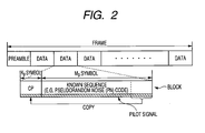
  • a transmission system that transmits a block having the CP added to data (a transmitted signal) as shown in Fig. 2 .
  • the CP is formed by copying the last K symbols of a data main body part (a useful block time) composed of M symbols before the data main body part.
  • an OFDM (Orthogonal Frequency Division Multiplexing) system or a single carrier block transmission system with cyclic prefix (refer it to as a SC-CP, hereinafter) to which the cyclic prefix is applied is well-known.
  • a received signal comes under an influence by a channel and a process for removing this influence in a receiver is referred to as an equalizing process.
  • the equalizing process is ordinarily realized by a filter having performance inverse to the transfer function of the channel.
  • an equalizer 100 of a discrete frequency domain is used in the block transmission system using the cyclic prefix (SC-CP).
  • SC-CP cyclic prefix
  • a received signal vector after the CP is removed is discrete Fourier transformed, multiplied by a weight for each frequency component in a transformed domain and returned again to a signal of a time domain by an inverse discrete Fourier transform to realize an equalization.
  • Non-Patent Document 1 discloses that when a CP is added to a transmitted signal block, an inter-block interference can be removed by frequency domain equalizer (FDE) and a performance of it is improved.
  • the inter-block interference (refer it also to as an "IBI", hereinafter) arises in such a way that a delayed signal of a previous block generated in the channel is overlapped on a signal of a current block.
  • IBI frequency domain equalizer
  • H 0 ⁇ h L ⁇ h 0 0 ⁇ 0 ⁇ ⁇ ⁇ ⁇ ⁇ ⁇ ⁇ ⁇ 0 ⁇ ⁇ ⁇ 0 h L ⁇ h 0
  • Matrix size M + K ⁇ + 2 ⁇ M + K
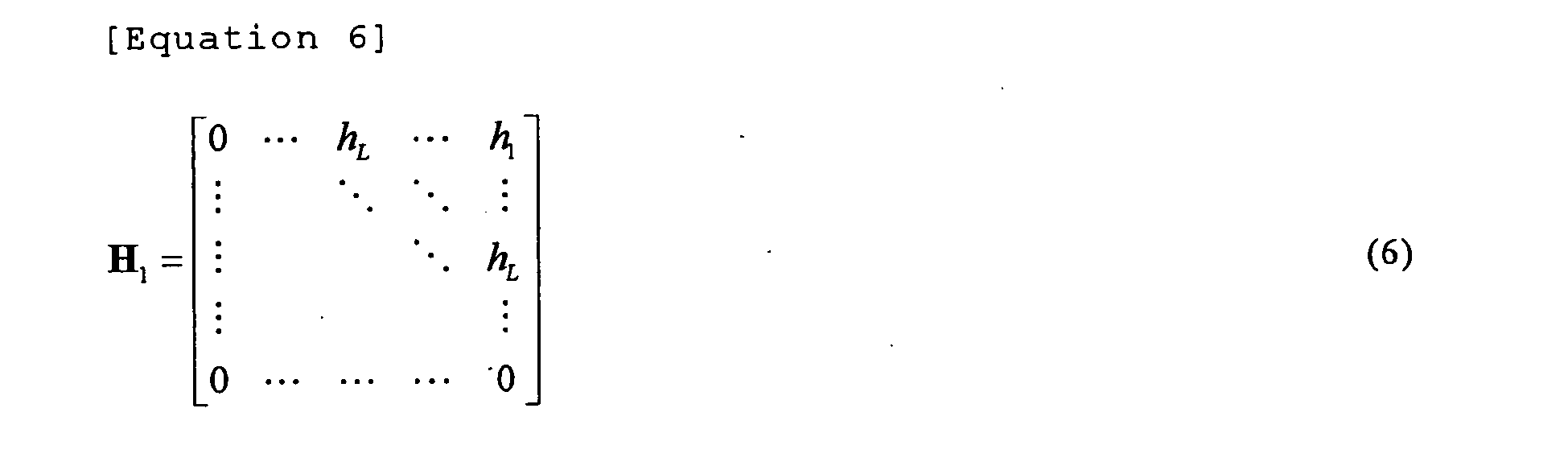
  • H is decomposed to two submatrices of (M+K)x (M+K), Equation 6
  • H 1 0 ⁇ h L ⁇ h 1 ⁇ ⁇ ⁇ ⁇ ⁇ ⁇ h L ⁇ ⁇ 0 ⁇ ⁇ ⁇ 0
  • H 0 h 0 ⁇ h 0 0 h L ⁇ ⁇ ⁇ 0 h L ⁇ h 0 the received signal block is expressed as described below.
  • a first term of the right side of the equation (8) shows a signal component from a (n-1) th transmitting block and represents a component of the inter-block interference (IBI).
  • IBI inter-block interference
  • a matrix having such a structure as shown in the equation (12) is called a circulant matrix which can be transformed using a unitary similarity by a "discrete Fourier transform” (DFT) matrix.
  • DFT discrete Fourier transform
  • the equalizing process after the CP is removed is expressed by an equation as described below.
  • the frequency domain equalizer uses discrete Fourier transform for the received signal block after the CP is removed, multiplies the received signal block by a weight for each frequency component in the frequency domain and returns again to a signal of a time domain by an inverse discrete Fourier transform.
  • the discrete frequency domain weight is expressed as a diagonal matrix, whose diagonal element is ⁇ 0 , ..., ⁇ M-1 ⁇
  • Non-Patent Document 1 discloses an equalizer weight of a zero forcing (ZF) criterion and an equalizer weight of a minimum mean-square-error(MMSE) criterion.
  • ZF zero forcing
  • MMSE minimum mean-square-error
  • A denotes the diagonal matrix with diagonal element which is ⁇ 0 , whil, ⁇ M-1 ⁇ of the discrete Fourier transform of the impulse response of the channel obtained from the equation (14). Simulation examples using these weights are also disclosed in the Non-Patent Document 1 (Fig. 8).
  • the MMSE criterion equalizer of the single carrier block transmission system is more excellent in its performance than the ZF criterion equalizer.
  • a main reason why the ZF criterion equalizer is inferior to the MMSE criterion equalizer is a noise enhancement.
  • the noise enhancement is a phenomenon that when a channel response of a communication path in a certain frequency i (0 ⁇ i ⁇ M-1) is 0 or near to 0, a weight in the frequency i shows a very large value so that noise is amplified.
  • Non-Patent Document 1 Kazunori Hayashi “Fundamentals of Modulation/Demodulation and Equalization Technologies) Proc. MWE2004,pp. 523-532, 2004.
  • the delayed signal of the previous block needs to remain within the CP of the current block and a situation must be avoided that the delayed signal of the previous block exceeds the CP of the current block.
  • K ⁇ L needs to be established. That is, the length K of the CP needs to be equal to or larger than the order number L of the channel.
  • the performance of the frequency domain equalizer suffers from IBI abruptly.
  • the length K of the CP needs to be increased.
  • a rate of the CP occupied in the block is increased and a rate of the useful block length is reduced and deteriorate a channel capacity.
  • the present invention concerns a receiver for a transmission system using a block including a plurality of symbols.
  • the receiver for a transmission system comprises: a transfer function estimating part that estimates a transfer function of a channel; and an inter-block interference component generating part that generates a replica of an inter-block interference component from a previous block to a current block in accordance with the transfer function estimated in the transfer function estimating part and a received signal of the previous block and is characterized in that the inter-block interference component of a received signal is reduced by using the replica of the inter-block interference component.
  • the replica of the inter-block interference component is generated so that the inter-block interference component can be reduced, even when the order number of the channel is larger than the length of a redundant signal, an influence of the inter-block interference can be reduced.
  • the block preferably has the redundant signal serving as a guard interval to the inter-block interference from the previous block to the current block. Further, the redundant signal preferably includes a cyclic prefix. The redundant signal may include other signal than the cyclic prefix.
  • An equalizer is preferably provided that carries out a process for reducing, by the calculation of a prescribed equation, an interference component between the symbols generated depending on whether a cyclic prefix length is small or cyclic prefix does not exist, from the received signal in which the inter-block interference component is reduced.
  • a received signal block after the inter-block interference component is reduced includes a new interference component between the symbols that cannot be satisfactorily equalized in the usual process explained in the background art.
  • the interference component between the symbols can be reduced by the equalizer for reducing the interference component between the symbols.
  • an inter-symbol interference component generating part is preferably provided that generates a replica of an interference component between the symbols in the current clock in accordance with the received signal in which the inter-block interference component is reduced and the estimated transfer function of the channel.
  • the interference component between the symbols of the received signal is preferably reduced by using the replica of the interference component between the symbols.
  • the inter-symbol interference component generating part preferably carries out a calculation by any one of equations (34) to (36) in a below-described embodiment to obtain a decided value as a transmitted signal block, which is used for generating the replica of the interference component between the symbols, from the received signal in which the inter-block interference component is reduced.
  • equations (34) to (36) will be described in the below-described embodiment.
  • the inter-symbol interference component generating part is preferably formed so as to generate the replica of the interference component between the symbols from the decided value as the transmitted signal block in accordance with equations (37) to (41) in the below-described embodiment. In this case, the calculation of signal processing can be faster and performances can be more improved.
  • the receiver preferably includes an order number decision part that estimates the order number of the channel to decide whether or not the order number of the channel is larger than the length of the redundant signal. In this case, the receiver can grasp order number of the channel to carry out a proper process.
  • the present invention concerns a transmission method that transmits a block including a plurality of symbols.
  • the transmission method comprises a step of estimating a transfer function of a channel; a step of generating a replica of an inter-block interference component from a previous block to a current block in accordance with the estimated transfer function and a received signal of the previous block; and a step of reducing the inter-block interference component of a received signal by using the replica of the inter-block interference component.
  • the present invention concerns a transmission system that transmits a block including a plurality of symbols from a transmitter and receives the block by a receiver.
  • the receiver comprises: a transfer function estimating part that estimates a transfer function of a channel; and an inter-block interference component generating part that generates a replica of an inter-block interference component from a previous block to a current block in accordance with the transfer function estimated in the transfer function estimating part and a received signal of the previous block and is characterized in that the inter-block interference component of a received signal is reduced by using the replica of the inter-block interference component.
  • Fig. 1 is a block diagram of a single carrier block transmission (SC-CP) system to which a cyclic prefix is applied.
  • This transmission system includes a transmitter 10 and a receiver 20. A signal transmitted from the transmitter 10 is received by the receiver 20 via a channel 30.
  • Fig. 2 shows a transmission data form in the transmission system.
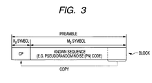
  • a preamble block illustrated in Fig. 3
  • the data block (sometimes refer it to only as a block, hereinafter) is formed by adding a CP (K symbols) to a plurality of base band signals (M symbols).
  • K symbols a CP
  • M symbols base band signals
  • the preamble block (sometimes refer it to only as a preamble, hereinafter) means a known signal added to the head part of the frame.
  • the preamble block is used to estimate a frequency transfer function.
  • the preamble block is used to take a synchronization of clock and carrier frequency in the receiver.
  • PN Physical Random Noise
  • the chirp signal is a "sine wave in which a frequency linearly increases" and a method for generating the chirp signal is described in Document [ J.Cioffi and J.A.C.Bingham, A Data-Driven Multitone Echo Canceller, IEEE Transactions on Communications, Vol. 42. No.10, P.2853-2869, 1994B, p.2866 ].
  • the chirp signal has a merit that amplitude can be made to be fixed both in a time domain and a frequency domain.
  • a pilot signal is a known signal embedded in a data block and used to estimate a frequency transfer function in the single carrier transmission system.
  • the pilot signal is used to take a synchronization of clock and carrier frequency in the receiver.
  • Fig. 3 of Document K. Hayashi and S. Hara, A New Spatio-Temporal Equalization Method Based on Estimated Channel Response, IEEE Transactions on Vehicular Technology, Vol. 50, No.5, p.1250-1259, 2001 .].
  • a transmitted signal is divided into blocks at intervals of M symbols as shown in the above-described equation (1).
  • the preamble block is also formed and added to the head part of the plurality of data blocks.
  • the preamble block formed here also has a CP and the length Kp of the CP of the preamble is larger than the length K of the CP of the data block. Further, the length Kp of the CP of the preamble is set to be equal to or smaller than a length Mp of a known sequence of the preamble (MP ⁇ Kp ⁇ L > K).
  • the length Kp of the CP of the preamble block is apt to be larger than the order number of the channel 30.
  • the transfer function can be assuredly estimated in the receiver 20.
  • the CP of the data block may be shorter than an ordinary length (smaller than the order number of the channel) to improve a channel capacity.
  • the pilot signal is also formed and synthesized with a transmitted signal block. Further, the cyclic prefix (CP) is added that is formed by copying the last part of the block in the head part.
  • CP cyclic prefix
  • the receiver 20 receives the signal and demodulates the signal.
  • the receiver 20 includes a transfer function estimating part 21 of the channel.
  • the transfer function is estimated on the basis of a result obtained from a Fast Fourier transform (FFT) of the preamble or the pilot signal.
  • FFT Fast Fourier transform
  • the transfer function can be estimated only by the preamble in the head part of the frame, however, the estimated transfer function may be updated (corrected) by the pilot signal synthesized with the block, so that the transfer function of the channel changing dynamically can be more precisely estimated.
  • the receiver 20 also includes an order number decision part 22 of the channel 30 to estimate the order number L of the channel 30.
  • the order number L may be decided by the Fast Fourier transform (FFT) as in the transfer function estimating part 21 or by an order number deciding algorithm such as an AIC (Akaike Information Criterion) or a MDL (Minimum Description Length) algorithm.
  • FFT Fast Fourier transform
  • AIC Akaike Information Criterion
  • MDL Minimum Description Length
  • the estimated transfer function is supplied to an equalizer 23 for an equalizing process of a received signal. Further, when the order number L of the channel is larger than the length K of the CP (L > K), the estimated transfer function is also supplied to an inter-block interference component (IBI replica) generating part 24.
  • IBI replica inter-block interference component
  • the inter-block interference component generating part 24 generates, when L > K, an inter-block interference component (IBI replica) from a previous block to a current block.
  • the IBI replica generated in the inter-block interference component generating part 24 is subtracted from the received signal r(n)(the current block) so that the inter-block interference (IBI) component can be reduced and a bit error rate can be improved.
  • K ⁇ L a process for subtracting the replica of the inter-block interference component from the received signal r(n) is not carried out and the usual process described in the background art is carried out.
  • the IBI replica is generated from the transfer function of the channel 30 supplied from the transfer function estimating part 21 and a decided value of a signal s(n-1) of the previous block.
  • the decided signal of the previous block is obtained by an equalizing process of the equalizer 23, and is regarded as the transmitted signal s(n-1) of the previous block. It supplied to a next block by a one block delay part 25.
  • a signal decision part 26 serves to determine a symbol by a prescribed criterion (a threshold value).
  • n ( n ) R CP ⁇ ( n ).
  • R CP H 0 T cp , R CP H 1 T cp , C, C ISI , and C IBI are respectively expressed as shown below.
  • C h 0 0 ⁇ 0 0 0 0 0 0 0 0 0 0 0 0 0 0 0 0 ⁇ 0 0 ⁇ 0 h L
  • C IBI s(n-1) designates the inter-block interference component from the previous block to the current block and C ISI s(n) designates an inter-symbol interference (ISI) component in the current block that is newly generated depending on whether the length of the cyclic prefix is short or the cyclic prefix does not exist.
  • ISI inter-symbol interference
  • the IBI component is reduced and the bit error rate can be improved.
  • the ISI component is the inter-symbol interference or the interference between the symbols that is newly generated depending on whether the length of the cyclic prefix is short or the cyclic prefix does not exist.
  • the equalizer 23 of this embodiment carries out a calculation of a below-described equation (26) to cancel the ISI component.
  • D designates a DFT matrix expressed by the equation (15).
  • designates a diagonal matrix having ⁇ 0 , across, ⁇ M-1 ⁇ as diagonal elements and is given by below-described equations.
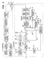
  • Figs. 5 and 6 show a transmission system according to a second embodiment.
  • a receiver 20 of this transmission system has a structure that an inter-symbol interference component generating part 27 for generating a replica of an inter-symbol interference component is added to the receiver 20 shown in Fig. 1 to add the replica of the inter-symbol interference component to a received signal in which the replica of an inter-block interference component is removed.
  • the inter-symbol interference component generating part 27 includes an equalizer 27a and a signal decision part 27b similar to the equalizer 23 and the signal decision part 26 shown in Fig. 1 .
  • a "temporarily decided" transmitted signal block is obtained from a received signal block after the replica of the inter-block interference component is removed by the equalizer 27a and the signal decision part 27b.
  • the inter-symbol interference component generating part 27 has an ISI replica generating part 27c.
  • This ISI replica generating part 27c generates the replica C ISI s(n) (ISI replica) of the inter-symbol interference component from the temporarily decided transmitted signal block to add the ISI replica to the received signal after the replica (IBI replica) of the inter-block interference component is removed.
  • the received signal after the ISI replica is added is expressed as shown below.
  • the equalizer 27a of the inter-symbol interference component generating part 27 has the same variations as some variations of calculating equations of the equalizing process in the equalizer 23 in Fig. 1 . That is, the equalizer 27a may carry out any of the calculations of the equation (26), the equation (27) or the equation (28). Further, the equalizer 27a may carry out the calculations of the equation (18) and the equation (19).
  • ⁇ ( R CP H 0 T CP ) -1 r ( n ) ⁇ means a result obtained by deciding ( R CP H 0 T CP ) -1 r ( n ) in a demodulator.
  • ⁇ . > indicates a decided result obtained by deciding a signal described in ⁇ > in the signal decision part (a demodulator) 27b as described above.
  • the above-described thing is applied to below-described equations (35) and (36).
  • ⁇ 0 , etc, ⁇ M-1 ⁇ is preferably given by the equations (29) to (32).
  • C ISI s(n) may be simply calculated, however, in order to carry out the calculation at low complexity and improve performance, a structure shown in Fig. 6 is preferably provided to carry out the calculations of below-described equations (37) to (41).
  • the below-described equation (37) is based on a matrix of C ISI shown in the equation (23) and means that an only submatrix (a specific submatrix G) shown by the below-described equation (38) may be enough to calculate and generate the ISI replica C ISI s(n), and all elements of s(n) is not required.
  • the performance are improved. This is because the submatrix (the specific submatrix G) shown in the equation (38) does not comprise weak elements (M-L+1 to M-K th element) of s (n) (which is input of the ISI replica generating part 27c) suffered from the influence of the ISI, but strong elements (more definite elements) except the M-L+1 to M-K th elements.

Landscapes

  • Engineering & Computer Science (AREA)
  • Power Engineering (AREA)
  • Computer Networks & Wireless Communication (AREA)
  • Signal Processing (AREA)
  • Cable Transmission Systems, Equalization Of Radio And Reduction Of Echo (AREA)
  • Digital Transmission Methods That Use Modulated Carrier Waves (AREA)

Abstract

To reduce the influence of inter-block interference even when the order number of the channel (physically corresponding to the impulse response length of the channel) is larger than the CP length. A receiver 20 for a transmission system using a block including a plurality of symbols, comprises a transfer function estimating part 21 which estimates a transfer function of a channel, and an inter-block interference component generating part 24 which generates a replica of an inter-block interference component from a previous block to a current block in accordance with the transfer function h estimated in the transfer function estimating part 21 and a received signal s(n-1) of the previous block, wherein the inter-block interference component of a received signal is reduced by using the replica of the inter-block interference component.

Description

    Technical Field
  • The present invention relates to a receiver, a transmission method and a transmission system and more preferably to a transmission system using a block in which a redundant signal such as a cyclic prefix (refer it to as a "CP", hereinafter) is inserted to avoid an inter-block interference from a previous block to a current block.
  • Background Art
  • In the field of a high speed digital transmission, a transmission system is known that transmits a block having the CP added to data (a transmitted signal) as shown in Fig. 2. The CP is formed by copying the last K symbols of a data main body part (a useful block time) composed of M symbols before the data main body part.
  • As such a transmission system, an OFDM (Orthogonal Frequency Division Multiplexing) system or a single carrier block transmission system with cyclic prefix (refer it to as a SC-CP, hereinafter) to which the cyclic prefix is applied is well-known.
  • Here, a received signal comes under an influence by a channel and a process for removing this influence in a receiver is referred to as an equalizing process. The equalizing process is ordinarily realized by a filter having performance inverse to the transfer function of the channel.
  • As shown in Fig.7, in the block transmission system using the cyclic prefix (SC-CP), an equalizer 100 of a discrete frequency domain is used. In this frequency domain equalizer, a received signal vector after the CP is removed is discrete Fourier transformed, multiplied by a weight for each frequency component in a transformed domain and returned again to a signal of a time domain by an inverse discrete Fourier transform to realize an equalization.
    The functions of other structures in Fig. 7 will be apparent from the explanation of below-described embodiments.
  • Non-Patent Document 1 discloses that when a CP is added to a transmitted signal block, an inter-block interference can be removed by frequency domain equalizer (FDE) and a performance of it is improved.
    The inter-block interference (refer it also to as an "IBI", hereinafter) arises in such a way that a delayed signal of a previous block generated in the channel is overlapped on a signal of a current block. When it is assumed that the CP is inserted as the guard interval between the blocks, even if the delayed signal of the previous block remains within the CP of the current block, an influence by the inter-block interference can be removed.
  • In order to explain the above-described thing in detail below, a process from the transmitting signal to the equalizing process is numerically expressed. Initially, in a transmitter, the transmitted signal is divided into blocks at intervals of M symbols (form a useful block time). In a below-described equation (1), n indicates a number attached to each block. Equation 1 s n = s 0 n , s 1 n , , s M - 1 n T
    Figure imgb0001
  • The CP is added to the useful block so that a block having the CP is formed and this block is transmitted. Equation 2 s ˙ n = T CP s n
    Figure imgb0002
  • In this case, TCP represents an operation for copying the last K components of the useful block s(n) in the head part in order just as it is. Equation 3 T CP = 0 K × M - K I K I M Matrix size : M + K × M
    Figure imgb0003
  • Assuming that an impulse response of the channel (a communication path) is h = {h0, h1, ..., hL}, a received signal block in the receiver is expressed by a below-described equation. Equation 4 r ˙ n = r ˙ 0 n , , r ˙ M + K - 1 n T = H s ˙ n - 1 s ˙ n
    Figure imgb0004
  • In this case, H is expressed as shown below. Equation 5 H = 0 h L h 0 0 0 0 0 0 h L h 0 Matrix size : M + K × + 2 M + K
    Figure imgb0005
  • Further, H is decomposed to two submatrices of (M+K)x (M+K), Equation 6 H 1 = 0 h L h 1 h L 0 0
    Figure imgb0006
    Equation 7 H 0 = h 0 h 0 0 h L 0 h L h 0
    Figure imgb0007

    the received signal block is expressed as described below. Equation 8 r ˙ n = H 1 s ˙ n - 1 + H 0 s ˙ n + n ˙ n = H 1 T CP s n - 1 + H 0 T CP s n + n ˙ n Matrix size : M + K × 1
    Figure imgb0008

    Here, a first term of the right side of the equation (8) shows a signal component from a (n-1) th transmitting block and represents a component of the inter-block interference (IBI).
  • At a receiver, the CP is removed. This is expressed by a below-described equation. Equation 9 r n = R CP r ˙ n = R CP H 1 T CP s n - 1 + R CP H 0 T CP s n + R CP n ˙ n Matrix size : M × 1
    Figure imgb0009
  • In this case, Equation 10 R CP = 0 M × K I M Matrix size : M × M + K
    Figure imgb0010
  • At this time, for the length K of the CP and the order number L of the channel (physically corresponding to the impulse response length of the channel), K ≧ L is assumed. That is, when the length K of the CP is equal to or larger than the order number L of the channel, since RCP H1 = 0, irrespective of the transmitted signal block, the received signal r(n) after the CP is removed is expressed by a below-described equation and the inter-block interference component is removed. Equation 11 r n = R CP H 0 s ˙ n + R CP n ˙ n = R CP H 0 T CP s n + R CP n ˙ n
    Figure imgb0011
  • When RCPH0TCP of the equation (11) is expanded, a below-described equation is obtained. Equation 12 R CP H 0 T CP = h 0 0 0 h L h 1 h 0 h L h L 0 0 0 0 0 h L h 0 = C CP
    Figure imgb0012
  • A matrix having such a structure as shown in the equation (12) is called a circulant matrix which can be transformed using a unitary similarity by a "discrete Fourier transform" (DFT) matrix.
  • When the nature of the circulant matrix is used, a below-described equation can be obtained. Equation 13 C CP = D H ΛD
    Figure imgb0013
  • In this case, Equation 14 Λ = λ 0 λ M - 1 = D h 0 h L h M - L - 1
    Figure imgb0014
    Equation 15 D = 1 1 1 1 e - j 2 π × 1 × 1 M e - j 2 π × 1 × M - 1 M 1 e - j 2 π × M - 1 × 1 M e - j 2 π × M - 1 × M - 1 M
    Figure imgb0015
  • When a noise component of a second term of the right side of the equation (11) is replaced by n (n), the received signal r(n) after the CP is removed can be expressed as described below. Equation 16 r n = D H ΛDs n + n n
    Figure imgb0016
  • The equalizing process after the CP is removed is expressed by an equation as described below. The frequency domain equalizer uses discrete Fourier transform for the received signal block after the CP is removed, multiplies the received signal block by a weight for each frequency component in the frequency domain and returns again to a signal of a time domain by an inverse discrete Fourier transform. Assuming that the discrete frequency domain weight is expressed as a diagonal matrix, whose diagonal element is {γ0, ..., γM-1}, an output of the equalizer is expressed by a below-described equation. Equation 17 s ^ n = D H ΓD D H ΛDs n = D H ΓΛDs n
    Figure imgb0017
  • Further, Non-Patent Document 1 discloses an equalizer weight of a zero forcing (ZF) criterion and an equalizer weight of a minimum mean-square-error(MMSE) criterion.
  • ZF equalizer weight Equation 18 γ i = 1 λ i i = 0 , , M - 1
    Figure imgb0018
  • MMSE equalizer weight Equation 19 γ i = λ i * λ i 2 + σ n 2 / σ s 2 , i = 0 , , M - 1
    Figure imgb0019

    σ s 2 is a variance of a signal s(n) and, σ n 2 is a variance of noise n(n)
  • Here, A denotes the diagonal matrix with diagonal element which is {λ0,......, λM-1} of the discrete Fourier transform of the impulse response of the channel obtained from the equation (14). Simulation examples using these weights are also disclosed in the Non-Patent Document 1 (Fig. 8). The MMSE criterion equalizer of the single carrier block transmission system is more excellent in its performance than the ZF criterion equalizer.
    A main reason why the ZF criterion equalizer is inferior to the MMSE criterion equalizer is a noise enhancement. The noise enhancement is a phenomenon that when a channel response of a communication path in a certain frequency i (0≤i≤M-1) is 0 or near to 0, a weight in the frequency i shows a very large value so that noise is amplified.
  • Non-Patent Document 1: Kazunori Hayashi "Fundamentals of Modulation/Demodulation and Equalization Technologies) Proc. MWE2004,pp. 523-532, 2004.
  • Disclosure of the Invention Problems that the Invention is to Solve
  • As described above about the equations (9) and (11), in order to avoid the inter-block interference, the delayed signal of the previous block needs to remain within the CP of the current block and a situation must be avoided that the delayed signal of the previous block exceeds the CP of the current block.
  • Namely, in order to avoid the inter-block interference, for the length K of the CP and the order number L of the channel (physically corresponding to the impulse response length of the channel), K ≧ L needs to be established. That is, the length K of the CP needs to be equal to or larger than the order number L of the channel.
    On the contrary, when the order number L of the channel is longer than the length K of the CP, the performance of the frequency domain equalizer suffers from IBI abruptly.
  • On the other hand, since the order number of the channel is varied depending on a communication environment, when the length of the CP is to be determined with a margin to avoid the inter-block interference, the length K of the CP needs to be increased. Thus, a rate of the CP occupied in the block is increased and a rate of the useful block length is reduced and deteriorate a channel capacity.
  • Thus, it is an object of the present invention to reduce an influence of an inter-block interference even when an order number of a channel (physically corresponding to an impulse response length of a channel) is larger than the length of a redundant signal such as a CP.
  • Means for Solving the Problems
  • The present invention concerns a receiver for a transmission system using a block including a plurality of symbols. The receiver for a transmission system comprises: a transfer function estimating part that estimates a transfer function of a channel; and an inter-block interference component generating part that generates a replica of an inter-block interference component from a previous block to a current block in accordance with the transfer function estimated in the transfer function estimating part and a received signal of the previous block and is characterized in that the inter-block interference component of a received signal is reduced by using the replica of the inter-block interference component.
  • According to the present invention, since the replica of the inter-block interference component is generated so that the inter-block interference component can be reduced, even when the order number of the channel is larger than the length of a redundant signal, an influence of the inter-block interference can be reduced.
    Further, according to the present invention, since the inter-block interference component can be reduced by the replica of the inter-block interference component, even when the block does not have the redundant signal (the length of the redundant signal = 0), the influence of the inter-block interference can be reduced. That is, even when the order number of the channel is larger than the length (including the length of the redundant signal = 0) of the redundant signal, the influence of the inter-block interference can be reduced, a good bit error rate can be obtained and a transmission of high reliability can be realized.
  • The block preferably has the redundant signal serving as a guard interval to the inter-block interference from the previous block to the current block. Further, the redundant signal preferably includes a cyclic prefix. The redundant signal may include other signal than the cyclic prefix.
  • An equalizer is preferably provided that carries out a process for reducing, by the calculation of a prescribed equation, an interference component between the symbols generated depending on whether a cyclic prefix length is small or cyclic prefix does not exist, from the received signal in which the inter-block interference component is reduced. When the length of the cyclic prefix is small or the cyclic prefix does not exist, a received signal block after the inter-block interference component is reduced includes a new interference component between the symbols that cannot be satisfactorily equalized in the usual process explained in the background art. However, the interference component between the symbols can be reduced by the equalizer for reducing the interference component between the symbols. In this case, as prescribed equations, for instance, an equation (26), an equation (27) and an equation (28) in a below-described embodiment can be used. The detail of these equations is explained in the below-described embodiment.
    "When the cyclic prefix does not exist" includes a case that the block has a redundant signal, however, the redundant signal does not include the cyclic prefix or a case that the block does not have a redundant signal.
  • Further, an inter-symbol interference component generating part is preferably provided that generates a replica of an interference component between the symbols in the current clock in accordance with the received signal in which the inter-block interference component is reduced and the estimated transfer function of the channel. The interference component between the symbols of the received signal is preferably reduced by using the replica of the interference component between the symbols. Thus, performance can be more improved.
  • The inter-symbol interference component generating part preferably carries out a calculation by any one of equations (34) to (36) in a below-described embodiment to obtain a decided value as a transmitted signal block, which is used for generating the replica of the interference component between the symbols, from the received signal in which the inter-block interference component is reduced. The detail of these equations (34) to (36) will be described in the below-described embodiment.
  • The inter-symbol interference component generating part is preferably formed so as to generate the replica of the interference component between the symbols from the decided value as the transmitted signal block in accordance with equations (37) to (41) in the below-described embodiment. In this case, the calculation of signal processing can be faster and performances can be more improved.
  • The receiver preferably includes an order number decision part that estimates the order number of the channel to decide whether or not the order number of the channel is larger than the length of the redundant signal. In this case, the receiver can grasp order number of the channel to carry out a proper process.
  • The present invention concerns a transmission method that transmits a block including a plurality of symbols. The transmission method comprises a step of estimating a transfer function of a channel; a step of generating a replica of an inter-block interference component from a previous block to a current block in accordance with the estimated transfer function and a received signal of the previous block; and a step of reducing the inter-block interference component of a received signal by using the replica of the inter-block interference component.
  • The present invention concerns a transmission system that transmits a block including a plurality of symbols from a transmitter and receives the block by a receiver. The receiver comprises: a transfer function estimating part that estimates a transfer function of a channel; and an inter-block interference component generating part that generates a replica of an inter-block interference component from a previous block to a current block in accordance with the transfer function estimated in the transfer function estimating part and a received signal of the previous block and is characterized in that the inter-block interference component of a received signal is reduced by using the replica of the inter-block interference component.
  • Brief Description of the Drawings
    • [Fig. 1] is a block diagram of a transmission system according to a first embodiment.
    • [Fig. 2] is a data structural diagram in an SC-CP transmission system.
    • [Fig. 3] is an example of a block of a preamble.
    • [Fig. 4] is a block diagram of an equalizer.
    • [Fig. 5] is a block diagram of a transmission system according to a second embodiment.
    • [Fig. 6] is ablockdiagramof aninter-symbol interference component generating part.
    • [Fig. 7] is a block diagram of a transmission system on the assumption that the length K of a CP is an order number L of the channel or larger.
    Best Mode for Carrying Out the Invention
  • Now, an embodiment of the present invention will be described by referring to the drawings.
    Fig. 1 is a block diagram of a single carrier block transmission (SC-CP) system to which a cyclic prefix is applied. This transmission system includes a transmitter 10 and a receiver 20. A signal transmitted from the transmitter 10 is received by the receiver 20 via a channel 30.
  • Further, Fig. 2 shows a transmission data form in the transmission system. As shown in Fig. 2, an object obtained by adding a preamble block (illustrated in Fig. 3) to a plurality of data blocks is called a frame. The data block (sometimes refer it to only as a block, hereinafter) is formed by adding a CP (K symbols) to a plurality of base band signals (M symbols). Normally, a plurality of bits are ordinarily allocated to one symbol. However, herein, only one bit may be allocated to one symbol.
  • The preamble block (sometimes refer it to only as a preamble, hereinafter) means a known signal added to the head part of the frame. In the single carrier block transmission, the preamble block is used to estimate a frequency transfer function. In addition thereto, the preamble block is used to take a synchronization of clock and carrier frequency in the receiver.
  • As the preamble, for instance, a PN (Pseudorandom Noise) signal sequence, a chirp signal or the like may be considered. Here, as for the detail of the PN signal, refer to [Mitsuo Yokoyama "Spread Spectrum communication System" scientific technology publishing company p.393, 6.3 PN Sequence].
  • The chirp signal is a "sine wave in which a frequency linearly increases" and a method for generating the chirp signal is described in Document [J.Cioffi and J.A.C.Bingham, A Data-Driven Multitone Echo Canceller, IEEE Transactions on Communications, Vol. 42. No.10, P.2853-2869, 1994B, p.2866]. The chirp signal has a merit that amplitude can be made to be fixed both in a time domain and a frequency domain.
  • A pilot signal is a known signal embedded in a data block and used to estimate a frequency transfer function in the single carrier transmission system. In addition thereto, the pilot signal is used to take a synchronization of clock and carrier frequency in the receiver. For instance, an example that uses the PN sequence suppressed to a data channel is shown in Fig. 3 of Document [K. Hayashi and S. Hara, A New Spatio-Temporal Equalization Method Based on Estimated Channel Response, IEEE Transactions on Vehicular Technology, Vol. 50, No.5, p.1250-1259, 2001.].
  • Returning to Fig. 1, a process in the transmitter 10 side is initially numerically expressed and described.
    A transmitted signal is divided into blocks at intervals of M symbols as shown in the above-described equation (1).
  • Further, in the transmitter 10, the preamble block is also formed and added to the head part of the plurality of data blocks. The preamble block formed here also has a CP and the length Kp of the CP of the preamble is larger than the length K of the CP of the data block. Further, the length Kp of the CP of the preamble is set to be equal to or smaller than a length Mp of a known sequence of the preamble (MP ≧ Kp ≧ L > K).
  • Thus, even when an order number of the channel 30 is larger than the length K of the CP of the data block, the length Kp of the CP of the preamble block is apt to be larger than the order number of the channel 30. Thus, the transfer function can be assuredly estimated in the receiver 20.
    Further, since only the length of the CP of the preamble may be increased, the CP of the data block may be shorter than an ordinary length (smaller than the order number of the channel) to improve a channel capacity.
  • Then, the pilot signal is also formed and synthesized with a transmitted signal block. Further, the cyclic prefix (CP) is added that is formed by copying the last part of the block in the head part.
    The frame formed in such a way is modulated to a radio frequency and transmitted to the channel 30.
  • The receiver 20 receives the signal and demodulates the signal. The receiver 20 includes a transfer function estimating part 21 of the channel. The transfer function estimating part 21 estimates the transfer function (an impulse response) h = {h0, h1, ...,hL} of the channel 30 on the basis of the preamble or the pilot signal. The transfer function is estimated on the basis of a result obtained from a Fast Fourier transform (FFT) of the preamble or the pilot signal.
    The transfer function can be estimated only by the preamble in the head part of the frame, however, the estimated transfer function may be updated (corrected) by the pilot signal synthesized with the block, so that the transfer function of the channel changing dynamically can be more precisely estimated.
  • Further, the receiver 20 also includes an order number decision part 22 of the channel 30 to estimate the order number L of the channel 30. The order number L may be decided by the Fast Fourier transform (FFT) as in the transfer function estimating part 21 or by an order number deciding algorithm such as an AIC (Akaike Information Criterion) or a MDL (Minimum Description Length) algorithm.
    When the order number is decided by the Fast Fourier transform, the order number may be obtained from a maximum delay of a signal when a noise part except the signal is removed by a given threshold value on the basis of the result of the Fast Fourier transform.
  • The estimated transfer function is supplied to an equalizer 23 for an equalizing process of a received signal. Further, when the order number L of the channel is larger than the length K of the CP (L > K), the estimated transfer function is also supplied to an inter-block interference component (IBI replica) generating part 24.
  • The inter-block interference component generating part 24 generates, when L > K, an inter-block interference component (IBI replica) from a previous block to a current block. The IBI replica generated in the inter-block interference component generating part 24 is subtracted from the received signal r(n)(the current block) so that the inter-block interference (IBI) component can be reduced and a bit error rate can be improved.
    When K ≧ L, a process for subtracting the replica of the inter-block interference component from the received signal r(n) is not carried out and the usual process described in the background art is carried out.
  • In the inter-block interference component generating part 24, the IBI replica is generated from the transfer function of the channel 30 supplied from the transfer function estimating part 21 and a decided value of a signal s(n-1) of the previous block.
    The decided signal of the previous block is obtained by an equalizing process of the equalizer 23, and is regarded as the transmitted signal s(n-1) of the previous block. It supplied to a next block by a one block delay part 25.
  • In Fig. 1, even in a signal having the same symbol, a phase or amplitude is not fixed due to the influence of noise. Thus, a signal decision part 26 serves to determine a symbol by a prescribed criterion (a threshold value).
  • The above-described process for reducing the inter-block interference component is described below in accordance with an equation. Initially, as described above, in the frequency domain equalizer to the single block carrier transmitted signal, when the order number of the channel (physically corresponding to an impulse response length) L is larger than the length K of the CP, a performance is abruptly deteriorated. Specifically, when L > K, since RcpH 1≠ 0, the equation (9) is expressed as described below. Here, Tcp, H0, H1, Rcp are defined in the equations (3), (6), (7) and (10) .
  • Equation 20 r n = R CP H 0 T CP s n + R CP H 1 T CP s n - 1 + R CP n = Cs n - C ISI s n + C ISI s n - 1 + n n
    Figure imgb0020

    In this case, n(n) = R CP (n).
  • In the equation (20), RCPH0Tcp, RCPH1Tcp, C, CISI, and CIBI are respectively expressed as shown below. Equation 21 R CP H 0 T CP = C - C ISI = h 0 0 0 h K h 1 h 0 0 h L h L h L 0 0 0 0 0 h L h 0
    Figure imgb0021
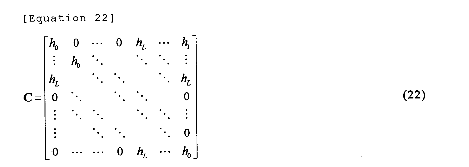
    Equation 22 C = h 0 0 0 h L h 1 h 0 h L h L 0 0 0 0 0 h L h 0
    Figure imgb0022
    Equation 23 C ISI = 0 0 h L h K + 1 0 0 h L 0 0 0 0 0
    Figure imgb0023
    Equation 24 R CP H 1 T CP = C IBI = 0 0 h L h K h L 0 0 0
    Figure imgb0024
  • In the equation (20), CIBIs(n-1) designates the inter-block interference component from the previous block to the current block and CISIs(n) designates an inter-symbol interference (ISI) component in the current block that is newly generated depending on whether the length of the cyclic prefix is short or the cyclic prefix does not exist.
  • In this embodiment, when L is larger than K, "an estimated value of CIBI" formed by the "estimated value of the transfer function h" and a "decided value of s (n-1)" are used to form the replica (IBI replica) of the inter-block interference component "CIBIs(n-1)" to subtract the IBI replica from the received signal r (n) . A signal obtained after the IBI replica is subtracted from the received signal r(n) is expressed by an equation (25).
  • Equation 25 r n = r n - C IBI s ^ n - 1 = r n - C IBI s ˜ n - 1 C - C ISI s n + n n
    Figure imgb0025
  • In the signal after the replica is subtracted as shown in the equation (25), the IBI component is reduced and the bit error rate can be improved.
  • However, in the equation (25), the ISI component still remains. The ISI component is the inter-symbol interference or the interference between the symbols that is newly generated depending on whether the length of the cyclic prefix is short or the cyclic prefix does not exist. As in this embodiment, when the short cyclic prefix length is smaller than the order number of the channel, a new inter-symbol interference component is generated by a delayed signal exceeding the cyclic prefix. Such an inter-symbol interference component cannot be satisfactorily equalized by the usual process described in the background art. The equalizer 23 of this embodiment carries out a calculation of a below-described equation (26) to cancel the ISI component. Here, the equalizer 23 for carrying out the calculation of the equation (26) is referred to as a ZF equalizer. Equation 26 s ^ ZF n = R CP H 0 T CP - 1 r n
    Figure imgb0026
  • Further, as another calculating equation for canceling the ISI component in the equalizer 23, a below-described equation (27) may be employed. Here, the equalizer 23 for carrying out the calculation of the equation (27) is referred to as an MMSE equalizer. Equation 27 s ^ MMSE n = R CP H 0 T CP H R CP H 0 T CP R CP H 0 T CP H + σ n 2 σ s 2 I M - 1 r n
    Figure imgb0027
  • The above-described equations (26) and (27) respectively indicate calculations of time domain and have relatively large computational complexity. Thus, to decrease the computational complexity, the calculation is preferably carried out in the frequency domain. Namely, as another calculating equation for canceling the ISI component in the equalizer 23, an equation (28) is preferable. In Fig. 4, the structure of the equalizer 23 for calculating the equation (28) is shown. Here, the equalizer 23 for carrying out the calculation of the equation (28) is referred to as a frequency domain equalizer. Equation 28 s ^ FDE n = D H ΓD r n
    Figure imgb0028
  • In the equation (28), D designates a DFT matrix expressed by the equation (15). Γ designates a diagonal matrix having {γ0,....., γM-1} as diagonal elements and is given by below-described equations.
  • Equation 29 γ m = λ m * - g m , n * λ m - g m , n 2 + i = 0 , i m M - 1 g m , i 2 + σ s 2 σ n 2
    Figure imgb0029
    Equation 30 g m , n = 1 M l = 0 L - K - 1 i = 0 l h L - i e j 2 π M n M - L + l - mi
    Figure imgb0030
    Equation 31 g m , m = 1 M l = 0 L - K - 1 i = 0 l h L - i e j 2 π M n M - L + l - i
    Figure imgb0031
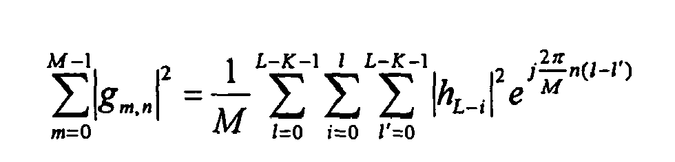
    Equation 32 m = 0 M - 1 g m , n 2 = 1 M l = 0 L - K - 1 i = 0 l = 0 L - K - 1 h L - i 2 e j 2 π M n l -
    Figure imgb0032
  • Figs. 5 and 6 show a transmission system according to a second embodiment. In the second embodiment, a part whose explanation is omitted is the same as that of the above-described embodiment.
    A receiver 20 of this transmission system has a structure that an inter-symbol interference component generating part 27 for generating a replica of an inter-symbol interference component is added to the receiver 20 shown in Fig. 1 to add the replica of the inter-symbol interference component to a received signal in which the replica of an inter-block interference component is removed.
  • The inter-symbol interference component generating part 27 includes an equalizer 27a and a signal decision part 27b similar to the equalizer 23 and the signal decision part 26 shown in Fig. 1. A "temporarily decided" transmitted signal block is obtained from a received signal block after the replica of the inter-block interference component is removed by the equalizer 27a and the signal decision part 27b.
  • The inter-symbol interference component generating part 27 has an ISI replica generating part 27c. This ISI replica generating part 27c generates the replica CISIs(n) (ISI replica) of the inter-symbol interference component from the temporarily decided transmitted signal block to add the ISI replica to the received signal after the replica (IBI replica) of the inter-block interference component is removed.
    The received signal after the ISI replica is added is expressed as shown below.
  • Equation 33 r ˜ n = r n + C ISI r ˜ n Cs n + n n
    Figure imgb0033
  • Here, the equalizer 27a of the inter-symbol interference component generating part 27 has the same variations as some variations of calculating equations of the equalizing process in the equalizer 23 in Fig. 1.
    That is, the equalizer 27a may carry out any of the calculations of the equation (26), the equation (27) or the equation (28). Further, the equalizer 27a may carry out the calculations of the equation (18) and the equation (19).
  • When the equalizer 27a uses the equation (26), a result temporarily decided as the transmitted signal in the inter-symbol interference component generating part 27 is expressed by a below-described equation. Equation 34 s ˜ n = s ^ ZF n = R CP H 0 T CP - 1 r n
    Figure imgb0034

    Here,〈(R CP H 0 T CP)-1 r (n)〉 means a result obtained by deciding (R CP H 0 T CP)-1 r (n) in a demodulator.
    In this case, in the equation (34), < . > indicates a decided result obtained by deciding a signal described in < > in the signal decision part (a demodulator) 27b as described above. The above-described thing is applied to below-described equations (35) and (36).
  • Further, when the equalizer 27a uses the equation (27), a result temporarily decided as the transmitted signal block in the inter-symbol interference component generating part 27 is expressed by a below-described equation. Equation 35 s ˜ n = s ^ MMSE n = R CP H 0 T CP H R CP H 0 T CP R CP H 0 T CP H + σ n 2 σ s 2 I M - 1 r n
    Figure imgb0035
  • Further, when the equalizer 27a uses the equation (28), a result temporarily decided as the transmitted signal block in the inter-symbol interference component generating part 27 is expressed by a below-described equation. Equation 36 s ˜ n = s ^ FDE n = D H ΓD r n
    Figure imgb0036
    Γ designates a diagonal matrix having {γ0, ..., γ M-1} as diagonal elements.
    In the equation (36), {γ0,....., γM-1} is preferably given by the equations (29) to (32).
  • In the ISI replica generating part 27c, CISIs(n) may be simply calculated, however, in order to carry out the calculation at low complexity and improve performance, a structure shown in Fig. 6 is preferably provided to carry out the calculations of below-described equations (37) to (41).
  • The below-described equation (37) is based on a matrix of CISI shown in the equation (23) and means that an only submatrix (a specific submatrix G) shown by the below-described equation (38) may be enough to calculate and generate the ISI replica CISIs(n), and all elements of s(n) is not required.
  • When the submatrix of the equation (38) is obtained, the performance are improved. This is because the submatrix (the specific submatrix G) shown in the equation (38) does not comprise weak elements (M-L+1 to M-K th element) of s (n) (which is input of the ISI replica generating part 27c) suffered from the influence of the ISI, but strong elements (more definite elements) except the M-L+1 to M-K th elements.
  • In other words, since the M-L+1 to M-K th elements of M elements suffer from the influence of the ISI more seriously than other elements, the temporarily decided values of s(n) obtained by the signal decision part 27b have a low reliability during a temporary decision. To use this character, as shown in the equation (41), (L-K) elements of the M-L+1 to M-K th elements of the temporarily decided values from the signal decision part 27b are not used in the ISI replica generating part 27c, and the specific submatrix G shown in the equation (38) comprises (M-L) elements of first to M-L th elements and K elements of M-K +1 to M th elements. Therefore, the performance are improved.
  • Equation 37 C ISI s n = C ISI 0 M - L × 1 s ˜ ˜ sub n 0 K × 1
    Figure imgb0037
    Equation 38 s ˜ ˜ sub n = P r ʺ n = E H E - 1 E H r ʺ n
    Figure imgb0038

    (Here, s ˜ ˜ sub n
    Figure imgb0039
    designates the above-described specific submatrix G.) Equation 39 E = h 0 0 h 0 h L - 1 h K
    Figure imgb0040
    Equation 40 r ʺ n = r M - L ʹ n , , r M - 1 ʹ n T
    Figure imgb0041
    Equation 41 r ʹ n = r 0 ʹ n r M - 1 ʹ n = r n - C s ˜ 0 n s ˜ M - L - 1 n 0 L - K × 1 s ˜ M - K n s ˜ M - 1 n
    Figure imgb0042
  • The present invention is not limited to the above-described embodiments and various modifications may be made without departing the intent of the present invention.
  • Drawings
  • Fig. 1
  • 10
    transmitter
    a
    signal buffer
    b
    signal mapping
    c
    synthesis of pilot and signal
    d
    addition of cyclic prefix
    e
    quadrature modulator
    f
    converter from IF to RF
    g
    preamble generator
    h
    pilot generator
    20
    receiver
    i
    case of L>K
    j
    remove of CP and extraction of pilot
    k
    extraction of preamble
    l
    quadrature demodulator
    m
    converter from RF to IF
    21
    transfer function estimation
    22
    order number decision
    23
    equalizer
    24
    IBI replica generator
    25
    one block delay
    26
    signal decision
    30
    channel
  • Fig. 2
  • a
    frame
    b
    preamble
    c
    data
    d
    Kp symbol
    e
    Mp symbol
    f
    known sequence (e.g. pseudorandom noise (PN) code)
    g
    block
    h
    pilot signal
    i
    copy
  • Fig. 3
  • a
    preamble
    b
    Kp symbol
    c
    Mp symbol
    d
    known sequence (e.g. pseudorandom noise (PN) code)
    e
    block
    f
    copy
  • Fig. 4
  • a
    frequency domain equalizer
  • Fig. 5
  • 10
    transmitter
    a
    signal buffer
    b
    signal mapping
    c
    synthesis of pilot and signal
    d
    addition of cyclic prefix
    e
    quadrature modulator
    f
    converter from IF to RF
    g
    preamble generator
    h
    pilot generator
    20
    receiver
    i
    case of L>K
    j
    remove of CP and extraction of pilot
    k
    extraction of preamble
    l
    quadrature demodulator
    m
    converter from RF to IF
    21
    transfer function estimation
    22
    order number decision
    23
    equalizer
    24
    IBI replica generator
    25
    one block delay
    26
    signal decision
    27a
    equalizer
    27b
    signal decision
    27c
    ISI replica generator
    30
    channel
  • Fig. 6
  • a
    matrix CISI generator equation (23)
    b
    matrix P generator equation (38)
    c
    matrix C generator equation (22)
    d
    order number L of h
    e
    signal decision
    f
    equation (40)
    g r'(n)
    extract r M - L ʹ n r M - 1 ʹ n
    Figure imgb0043
    which is M-L+1~M-th element of
    h
    equation (41)
    i
    making M-L+1~M-K-th element of s̃(n) to be 0
  • Fig. 7
  • A
    transmitter
    a
    signal buffer
    b
    signal mapping
    c
    synthesis of pilot and signal
    d
    addition of cyclic prefix
    e
    quadrature modulator
    f
    converter from IF to RF
    g
    preamble generator
    h
    pilot generator
    B
    receiver
    i
    signal decision
    j
    frequency domain equalizer
    k
    remove of CP and extraction of pilot
    l
    extraction of preamble
    m
    quadrature demodulator
    n
    converter from RF to IF
    o
    transfer function update
    p
    transfer function estimation
    C
    channel

Claims (12)

  1. A receiver for a transmission system using a block including a plurality of symbols, said receiver comprising:
    a transfer function estimating part that estimates a transfer function of a channel; and
    an inter-block interference component generating part that generates a replica of an inter-block interference component from a previous block to a current block in accordance with the transfer function estimated in the transfer function estimating part and a received signal of the previous block, characterized in that the inter-block interference component of a received signal is reduced by using the replica of the inter-block interference component.
  2. A receiver according to claim 1, characterized in that the block has a redundant signal serving as a guard interval for an inter-block interference from the previous block to the current block.
  3. A receiver according to claim 1, characterized in that the block has a redundant signal including a cyclic prefix.
  4. A receiver according to claim 1, further comprising:
    an equalizer that carries out a process for reducing an interference component between the symbols caused by whether a cyclic prefix length is small or cyclic prefix does not exist from the received signal in which the inter-block interference component is reduced.
  5. A receiver according to claim 1, further comprising:
    an equalizer that carries out a process for reducing an interference component between the symbols by performing a calculation according to any one of below-described equations (A), (B) and (C) with respect to the received signal from which the inter-block interference component is reduced. Equation 1 s ^ ZF n = R CP H 0 T CP - 1 r n A s ^ MMSE n = R CP H 0 T CP H R CP H 0 T CP R CP H 0 T CP H + σ n 2 σ s 2 I M - 1 r n B s ^ FDE n = D H ΓD r n C
    Figure imgb0044

    Here, r(n) designates a received signal block in which the inter-block interference component is reduced.
    ZF (n) designates an output of the equalizer.
    MMSE (n) designates an output of the equalizer.
    FDE (n) designates an output of the equalizer.
    R CP designates a matrix for removing a redundant signal.
    H 0 designates a matrix expressed as described below when it is assumed that an impulse response of a channel is h = {h0, h1, ...,hL}. H 0 = h 0 h 0 0 h L 0 h L h 0
    Figure imgb0045
    (Matrix size (M+K) x (M+K): M indicates a length of a block excluding a redundant signal, K indicates a length of a cyclic prefix)
    T CP designates a matrix for adding a redundant signal.
    I M designates a unit matrix of M x M.
    σ s 2
    Figure imgb0046
    is a variance of a signal s(n) and,
    σ n 2
    Figure imgb0047
    is a variance of noise n(n).
    [Equation 2]
    D is expressed by a below-described equation. D = 1 1 1 1 e - j 2 π × 1 × 1 M e - j 2 π × 1 × M - 1 M 1 e - j 2 π × M - 1 × 1 M e - j 2 π × M - 1 × ( M - ) 1 M
    Figure imgb0048

    (M designates a length of a block excluding a redundant signal)
    Γ designates a diagonal matrix having {γ0, ....., γM-1} as diagonal elements and is given by below-described equations. γ m = λ m * - g m , n * λ m - g m , n 2 + i = 0 , i m M - 1 g m , i 2 + σ s 2 σ n 2
    Figure imgb0049
    x* designates a complex conjugate of x and A = {λ0,...., λM-1} designates a discrete Fourier transform of an impulse response of a channel h = {h0, h1, ...,hL}. g m , n = 1 M l = 0 L - K - 1 i = 0 l h L - i e j 2 π M n M - L + l - mi
    Figure imgb0050
    g m , m = 1 M l = 0 L - K - 1 i = 0 l h L - i e j 2 π M n M - L + l - i
    Figure imgb0051
    m = 0 M - 1 g m , n 2 = 1 M l = 0 L - K - 1 i = 0 l = 0 L - K - 1 h L - i 2 e j 2 π M n l -
    Figure imgb0052
  6. A receiver according to claim 1, further comprising:
    an inter-symbol interference component generating part that generates a replica of an interference component between the symbols in the current block in accordance with the received signal in which the inter-block interference component is reduced and the estimated transfer function of the channel,
    wherein the interference component between the symbols of the received signal is reduced by using the replica of the interference component between the symbols.
  7. A receiver according to claim 6, wherein the inter-symbol interference component generating part carries out a calculation by any one of below-described equations (D), (E) and (F) to get a decided value of a transmitted signal block used for generating the replica of the interference component between the symbols from the received signal in which the inter-block interference component is reduced. Equation 3 s ˜ n = s ^ ZF n = R CP H 0 T CP - 1 r n D s ˜ n = s ^ MMSE n = R CP H 0 T CP H R CP H 0 T CP R CP H 0 T CP H + σ n 2 σ s 2 I M - 1 r n E s ˜ n = s ^ FDE n = D H ΓD r n F
    Figure imgb0053

    Here, r (n) designates a received signal block in which the inter-block interference component is reduced.
    ZF (n) designates an output of the equalizer.
    MMSE (n) designates an output of the equalizer.
    FDE (n) designates an output of the equalizer.
    (n) designates a decided value of a transmitted signal block.
    R CP designates a matrix for removing a redundant signal.
    H 0 designates a matrix expressed as described below when it is assumed that an impulse response of a channel is h = {h0, h1, ..., hL}. H 0 = h 0 h 0 0 h L 0 h L h 0
    Figure imgb0054
    (Matrix size (M+K) x (M+K): M indicates a length of a block excluding a redundant signal, K indicates a length of a cyclic prefix)
    T CP designates a matrix for adding a redundant signal.
    < . > indicates a result obtained by deciding a signal in < >.
    I M designates a unit matrix of M x M.
    σ s 2
    Figure imgb0055
    is a variance of a signal s(n) and,
    σ n 2
    Figure imgb0056
    is a variance of noise n(n).
    D is expressed by a below-described equation. D = 1 1 1 1 e - j 2 π × 1 × 1 M e - j 2 π × 1 × M - 1 M 1 e - j 2 π × M - 1 × 1 M e - j 2 π × M - 1 × ( M - ) 1 M
    Figure imgb0057

    (M designates a length of a block excluding a redundant signal)
    Γ designates a diagonal matrix having a weight {γ0,....., γM-1} of an equalizer in a discrete frequency domain as a diagonal element.
  8. A receiver according to claim 7, wherein γm (m= 0 to M-1) in the equation (F) of claim 7 is given by a below-described equation. γ m = λ m * - g m , n * λ m - g m , n 2 + i = 0 , i m M - 1 g m , i 2 + σ s 2 σ n 2
    Figure imgb0058

    x* designates a complex conjugate of x and A = {λ0, ...., λM-1} designates a discrete Fourier transform of an impulse response of a channel h = {h0, h1, ..., hL}. g m , n = 1 M l = 0 L - K - 1 i = 0 l h L - i e j 2 π M n M - L + l - mi
    Figure imgb0059
    g m , m = 1 M l = 0 L - K - 1 i = 0 l h L - i e j 2 π M n M - L + l - i
    Figure imgb0060
    m = 0 M - 1 g m , n 2 = 1 M l = 0 L - K - 1 i = 0 l = 0 L - K - 1 h L - i 2 e j 2 π M n l -
    Figure imgb0061
  9. A receiver according to claim 6, wherein the inter-symbol interference component generating part is designed to generate the replica of the interference component between the symbols in accordance with below-described equations. C ISI s n = C ISI 0 M - L × 1 s ˜ ˜ sub n 0 K × 1
    Figure imgb0062

    CISIs(n) designates a replica of an interference component between symbols. C ISI = 0 0 h L h K + 1 0 0 h L 0 0 0 0 0
    Figure imgb0063
    s ˜ ˜ sub n = P r ʺ n = E H E - 1 E H r ʺ n
    Figure imgb0064

    < . > shows a result obtained by deciding a signal in < >. E = h 0 0 h 0 h L - 1 h K
    Figure imgb0065
    r ʺ n = r M - L ʹ n , , r M - 1 ʹ n T
    Figure imgb0066
    r ʹ n = r 0 ʹ n r M - 1 ʹ n = r n - C s ˜ 0 n s ˜ M - L - 1 n 0 L - K × 1 s ˜ M - K n s ˜ M - 1 n
    Figure imgb0067
    r '(n) designates a received signal block in which an inter-block interference component is reduced.
    (n)={ 0(n),..., M-L-1(n)} designates a decided value of a transmitted signal block.
    h = {h0, h1, ..., hL} designates an impulse response of a channel.
    C = h 0 0 0 h L h 1 h 0 h L h L 0 0 0 0 0 h L h 0
    Figure imgb0068
  10. A receiver according to claim 1, further comprising:
    an order number decision part that decides the order number of the channel,
    wherein whether or not the order number of the channel is larger than the length of the redundant signal can be decided.
  11. A transmission method that transmits a block including a plurality of symbols; said transmission method comprising:
    a step of estimating a transfer function of a channel;
    a step of generating a replica of an inter-block interference component from a previous block to a current block in accordance with the estimated transfer function and a received signal of the previous block; and
    a step of reducing the inter-block interference component of a received signal by using the replica of the inter-block interference component.
  12. A transmission system that transmits a block including a plurality of symbols from a transmitter and receives the block by a receiver, said receiver comprising:
    a transfer function estimating part that estimates a transfer function of a channel; and
    an inter-block interference component generating part that generates a replica of an inter-block interference component from a previous block to a current block in accordance with the transfer function estimated in the transfer function estimating part and a received signal of the previous block, characterized in that the inter-block interference component of a received signal is reduced by using the replica of the inter-block interference component.
EP06810223A 2005-09-16 2006-09-15 Receiver, transmitting method, and transmitting system Withdrawn EP1933488A1 (en)

Applications Claiming Priority (2)

Application Number Priority Date Filing Date Title
JP2005271081 2005-09-16
PCT/JP2006/318431 WO2007032497A1 (en) 2005-09-16 2006-09-15 Receiver, transmitting method, and transmitting system

Publications (1)

Publication Number Publication Date
EP1933488A1 true EP1933488A1 (en) 2008-06-18

Family

ID=37865081

Family Applications (1)

Application Number Title Priority Date Filing Date
EP06810223A Withdrawn EP1933488A1 (en) 2005-09-16 2006-09-15 Receiver, transmitting method, and transmitting system

Country Status (4)

Country Link
US (1) US7953168B2 (en)
EP (1) EP1933488A1 (en)
JP (1) JPWO2007032497A1 (en)
WO (1) WO2007032497A1 (en)

Cited By (1)

* Cited by examiner, † Cited by third party
Publication number Priority date Publication date Assignee Title
US8462900B2 (en) 2008-02-27 2013-06-11 Panasonic Corporation Reception device, integrated circuit, and reception method

Families Citing this family (8)

* Cited by examiner, † Cited by third party
Publication number Priority date Publication date Assignee Title
JP4421635B2 (en) * 2007-06-18 2010-02-24 株式会社東芝 Wireless communication method and wireless communication device
JP4461162B2 (en) * 2007-07-02 2010-05-12 株式会社東芝 Terminal device
GB2463872B (en) * 2008-09-24 2012-04-18 Toshiba Res Europ Ltd A MMSE equaliser
US8611444B2 (en) * 2011-06-22 2013-12-17 Infomax Communication Co., Ltd. Receiver and signal receiving method thereof
WO2016002106A1 (en) 2014-06-30 2016-01-07 日本電気株式会社 Reception apparatus, reception method, and nontemporary computer readable medium
US9326295B1 (en) 2014-12-10 2016-04-26 Sony Corporation Method and apparatus for transmitting a-priori information in a communication system
US9455733B1 (en) * 2015-03-30 2016-09-27 Broadcom Corporation System and method for spread spectrum ADC noise reduction
US11343666B2 (en) * 2018-02-13 2022-05-24 Qualcomm Incorporated Waveform design of discovery signals

Family Cites Families (5)

* Cited by examiner, † Cited by third party
Publication number Priority date Publication date Assignee Title
JP4298320B2 (en) * 2002-11-08 2009-07-15 富士通株式会社 Receiver for OFDM transmission system
JP4055587B2 (en) * 2003-01-27 2008-03-05 株式会社豊田中央研究所 OFDM demodulation method and OFDM demodulation apparatus
JP4311132B2 (en) * 2003-08-29 2009-08-12 富士通株式会社 Receiver for OFDM transmission system
JP4421416B2 (en) * 2004-08-04 2010-02-24 富士通株式会社 OFDM receiver
US20060159187A1 (en) * 2005-01-14 2006-07-20 Haifeng Wang System and method for utilizing different known guard intervals in single/multiple carrier communication systems

Non-Patent Citations (1)

* Cited by examiner, † Cited by third party
Title
See references of WO2007032497A1 *

Cited By (1)

* Cited by examiner, † Cited by third party
Publication number Priority date Publication date Assignee Title
US8462900B2 (en) 2008-02-27 2013-06-11 Panasonic Corporation Reception device, integrated circuit, and reception method

Also Published As

Publication number Publication date
JPWO2007032497A1 (en) 2009-03-19
US7953168B2 (en) 2011-05-31
WO2007032497A1 (en) 2007-03-22
US20090268825A1 (en) 2009-10-29

Similar Documents

Publication Publication Date Title
KR100693778B1 (en) Training prefix modulation method and receiver
EP1617611B1 (en) Propagation path estimation method and apparatus
EP2120359B1 (en) Channel estimation device, equalization device, and equalization method in the estimation
US8054917B2 (en) Method and apparatus for advanced inter-carrier interference cancellation in orthogonal frequency division multiplexing (OFDM) channels
EP2228955B1 (en) System and method for OFDM reception in the presense of Doppler effect based on time domain windowing
US8824537B2 (en) Signal processing in wireless communication receivers
US12531771B2 (en) Transmitter and receiver for, and method of, transmitting and receiving symbols over time varying channels with Doppler spread
JPWO2017183631A1 (en) LOS-MIMO demodulation apparatus, communication apparatus, LOS-MIMO transmission system, LOS-MIMO demodulation method and program
EP1933488A1 (en) Receiver, transmitting method, and transmitting system
JP2003218826A (en) Method for receiving orthogonal frequency division multiplexed signal and receiver using the same
US7619964B2 (en) High doppler channel estimation for OFD multiple antenna systems
US8204465B2 (en) Receiver, transmitter, transmission system, and transmission method
US12107659B2 (en) System and method for designing low-complexity linear receivers for OTFS system
US8743946B2 (en) Frequency-domain equalization and combining for single carrier transmission
CN101133580A (en) receiving device
WO2015101672A1 (en) Methods and devices for doppler shift compensation in a mobile communication system
US7864901B2 (en) System, apparatus, and method for cancelling interferences of received signals
JP2006245810A (en) Fraction interval equalizer and receiver using the same
JP4501071B2 (en) Single carrier block transmission receiver and reception method
JP2006246128A (en) Filtering method and apparatus
KR100747593B1 (en) Apparatus for Channel Estimation of Wireless LAN Receiver based OFDM and its method
Artai et al. Determination of multipath channel parameters using wavelet decomposition
Mohammadi et al. MIMO filter-bank multicarrier system using unique word OFDM
Wang et al. Basis expansion model and doppler diversity techniques for frequency domain channel estimation and equalization in ds-cdma systems
Wang et al. On Frequency Domain Doppler Diversity Using Basis Expansion Model and EM-Based Algorithms in CDMA Systems

Legal Events

Date Code Title Description
PUAI Public reference made under article 153(3) epc to a published international application that has entered the european phase

Free format text: ORIGINAL CODE: 0009012

17P Request for examination filed

Effective date: 20080327

AK Designated contracting states

Kind code of ref document: A1

Designated state(s): DE FR GB

RBV Designated contracting states (corrected)

Designated state(s): DE FR GB

STAA Information on the status of an ep patent application or granted ep patent

Free format text: STATUS: THE APPLICATION HAS BEEN WITHDRAWN

18W Application withdrawn

Effective date: 20110117