EP1933328A2 - Surface laser treatment of zr-alloy fuel bundle material - Google Patents
Surface laser treatment of zr-alloy fuel bundle material Download PDFInfo
- Publication number
- EP1933328A2 EP1933328A2 EP07122212A EP07122212A EP1933328A2 EP 1933328 A2 EP1933328 A2 EP 1933328A2 EP 07122212 A EP07122212 A EP 07122212A EP 07122212 A EP07122212 A EP 07122212A EP 1933328 A2 EP1933328 A2 EP 1933328A2
- Authority
- EP
- European Patent Office
- Prior art keywords
- fuel
- alloy
- bundle material
- treating
- fuel bundle
- Prior art date
- Legal status (The legal status is an assumption and is not a legal conclusion. Google has not performed a legal analysis and makes no representation as to the accuracy of the status listed.)
- Ceased
Links
- 239000000446 fuel Substances 0.000 title claims abstract description 65
- 229910001093 Zr alloy Inorganic materials 0.000 title claims abstract description 38
- 239000000463 material Substances 0.000 title claims abstract description 23
- 238000013532 laser treatment Methods 0.000 title description 6
- 238000005260 corrosion Methods 0.000 claims abstract description 20
- 230000007797 corrosion Effects 0.000 claims abstract description 20
- 238000000034 method Methods 0.000 claims abstract description 15
- 125000006850 spacer group Chemical group 0.000 claims description 14
- 239000010410 layer Substances 0.000 claims description 11
- XLYOFNOQVPJJNP-UHFFFAOYSA-N water Substances O XLYOFNOQVPJJNP-UHFFFAOYSA-N 0.000 claims description 10
- 238000011282 treatment Methods 0.000 claims description 9
- 239000002344 surface layer Substances 0.000 claims description 5
- 238000009835 boiling Methods 0.000 claims description 4
- 239000003758 nuclear fuel Substances 0.000 claims description 4
- 229910019655 synthetic inorganic crystalline material Inorganic materials 0.000 description 17
- 238000012360 testing method Methods 0.000 description 9
- 239000011521 glass Substances 0.000 description 6
- 239000000956 alloy Substances 0.000 description 5
- UFHFLCQGNIYNRP-UHFFFAOYSA-N Hydrogen Chemical compound [H][H] UFHFLCQGNIYNRP-UHFFFAOYSA-N 0.000 description 4
- 229910045601 alloy Inorganic materials 0.000 description 4
- 229910019990 cerium-doped yttrium aluminum garnet Inorganic materials 0.000 description 4
- 238000005253 cladding Methods 0.000 description 4
- 239000001257 hydrogen Substances 0.000 description 4
- 229910052739 hydrogen Inorganic materials 0.000 description 4
- 229910001026 inconel Inorganic materials 0.000 description 4
- 230000000116 mitigating effect Effects 0.000 description 4
- 229910052779 Neodymium Inorganic materials 0.000 description 3
- 230000000712 assembly Effects 0.000 description 3
- 238000000429 assembly Methods 0.000 description 3
- 238000004519 manufacturing process Methods 0.000 description 3
- QEFYFXOXNSNQGX-UHFFFAOYSA-N neodymium atom Chemical compound [Nd] QEFYFXOXNSNQGX-UHFFFAOYSA-N 0.000 description 3
- 239000010955 niobium Substances 0.000 description 3
- 239000010935 stainless steel Substances 0.000 description 3
- 229910001220 stainless steel Inorganic materials 0.000 description 3
- XKRFYHLGVUSROY-UHFFFAOYSA-N Argon Chemical compound [Ar] XKRFYHLGVUSROY-UHFFFAOYSA-N 0.000 description 2
- PXHVJJICTQNCMI-UHFFFAOYSA-N Nickel Chemical compound [Ni] PXHVJJICTQNCMI-UHFFFAOYSA-N 0.000 description 2
- 229910052775 Thulium Inorganic materials 0.000 description 2
- 238000010521 absorption reaction Methods 0.000 description 2
- 238000006243 chemical reaction Methods 0.000 description 2
- 239000011651 chromium Substances 0.000 description 2
- 238000000576 coating method Methods 0.000 description 2
- 239000011572 manganese Substances 0.000 description 2
- 229910052751 metal Inorganic materials 0.000 description 2
- 239000002184 metal Substances 0.000 description 2
- 239000000203 mixture Substances 0.000 description 2
- 229910052758 niobium Inorganic materials 0.000 description 2
- GUCVJGMIXFAOAE-UHFFFAOYSA-N niobium atom Chemical compound [Nb] GUCVJGMIXFAOAE-UHFFFAOYSA-N 0.000 description 2
- VQMWBBYLQSCNPO-NJFSPNSNSA-N promethium-147 Chemical compound [147Pm] VQMWBBYLQSCNPO-NJFSPNSNSA-N 0.000 description 2
- 229910052594 sapphire Inorganic materials 0.000 description 2
- 239000010980 sapphire Substances 0.000 description 2
- IRPGOXJVTQTAAN-UHFFFAOYSA-N 2,2,3,3,3-pentafluoropropanal Chemical compound FC(F)(F)C(F)(F)C=O IRPGOXJVTQTAAN-UHFFFAOYSA-N 0.000 description 1
- KLZUFWVZNOTSEM-UHFFFAOYSA-K Aluminum fluoride Inorganic materials F[Al](F)F KLZUFWVZNOTSEM-UHFFFAOYSA-K 0.000 description 1
- OYPRJOBELJOOCE-UHFFFAOYSA-N Calcium Chemical compound [Ca] OYPRJOBELJOOCE-UHFFFAOYSA-N 0.000 description 1
- 229910052692 Dysprosium Inorganic materials 0.000 description 1
- 229910052691 Erbium Inorganic materials 0.000 description 1
- 229910052689 Holmium Inorganic materials 0.000 description 1
- -1 Inconel Chemical class 0.000 description 1
- PWHULOQIROXLJO-UHFFFAOYSA-N Manganese Chemical compound [Mn] PWHULOQIROXLJO-UHFFFAOYSA-N 0.000 description 1
- 229910052772 Samarium Inorganic materials 0.000 description 1
- 229910052771 Terbium Inorganic materials 0.000 description 1
- 229910009372 YVO4 Inorganic materials 0.000 description 1
- 229910052769 Ytterbium Inorganic materials 0.000 description 1
- QCWXUUIWCKQGHC-UHFFFAOYSA-N Zirconium Chemical compound [Zr] QCWXUUIWCKQGHC-UHFFFAOYSA-N 0.000 description 1
- DFENVCUUBABVIU-UHFFFAOYSA-N [Ca].[Y] Chemical compound [Ca].[Y] DFENVCUUBABVIU-UHFFFAOYSA-N 0.000 description 1
- SSCCKHJUOFTPEX-UHFFFAOYSA-N [Ce].[Nd] Chemical compound [Ce].[Nd] SSCCKHJUOFTPEX-UHFFFAOYSA-N 0.000 description 1
- WCULPSIYAQDUJW-UHFFFAOYSA-N [Li].[Sr] Chemical compound [Li].[Sr] WCULPSIYAQDUJW-UHFFFAOYSA-N 0.000 description 1
- PAXZWYXAXLLWTH-UHFFFAOYSA-N [Tm].[Cr].[Ho] Chemical compound [Tm].[Cr].[Ho] PAXZWYXAXLLWTH-UHFFFAOYSA-N 0.000 description 1
- 238000005275 alloying Methods 0.000 description 1
- JNDMLEXHDPKVFC-UHFFFAOYSA-N aluminum;oxygen(2-);yttrium(3+) Chemical compound [O-2].[O-2].[O-2].[Al+3].[Y+3] JNDMLEXHDPKVFC-UHFFFAOYSA-N 0.000 description 1
- 229910052786 argon Inorganic materials 0.000 description 1
- 238000005422 blasting Methods 0.000 description 1
- 229910052791 calcium Inorganic materials 0.000 description 1
- 239000011575 calcium Substances 0.000 description 1
- XQTIWNLDFPPCIU-UHFFFAOYSA-N cerium(3+) Chemical compound [Ce+3] XQTIWNLDFPPCIU-UHFFFAOYSA-N 0.000 description 1
- UUMMHAPECIIHJR-UHFFFAOYSA-N chromium(4+) Chemical compound [Cr+4] UUMMHAPECIIHJR-UHFFFAOYSA-N 0.000 description 1
- 229910001602 chrysoberyl Inorganic materials 0.000 description 1
- 239000011248 coating agent Substances 0.000 description 1
- 238000005097 cold rolling Methods 0.000 description 1
- 238000007796 conventional method Methods 0.000 description 1
- 238000001816 cooling Methods 0.000 description 1
- KBQHZAAAGSGFKK-UHFFFAOYSA-N dysprosium atom Chemical compound [Dy] KBQHZAAAGSGFKK-UHFFFAOYSA-N 0.000 description 1
- 230000000694 effects Effects 0.000 description 1
- UYAHIZSMUZPPFV-UHFFFAOYSA-N erbium Chemical compound [Er] UYAHIZSMUZPPFV-UHFFFAOYSA-N 0.000 description 1
- KWMNWMQPPKKDII-UHFFFAOYSA-N erbium ytterbium Chemical compound [Er].[Yb] KWMNWMQPPKKDII-UHFFFAOYSA-N 0.000 description 1
- 238000005530 etching Methods 0.000 description 1
- 230000004992 fission Effects 0.000 description 1
- 238000005242 forging Methods 0.000 description 1
- 238000010438 heat treatment Methods 0.000 description 1
- KJZYNXUDTRRSPN-UHFFFAOYSA-N holmium atom Chemical compound [Ho] KJZYNXUDTRRSPN-UHFFFAOYSA-N 0.000 description 1
- 238000005098 hot rolling Methods 0.000 description 1
- 229910052748 manganese Inorganic materials 0.000 description 1
- 239000011159 matrix material Substances 0.000 description 1
- 238000002844 melting Methods 0.000 description 1
- 230000008018 melting Effects 0.000 description 1
- 150000002739 metals Chemical class 0.000 description 1
- 238000012986 modification Methods 0.000 description 1
- 230000004048 modification Effects 0.000 description 1
- 229910052759 nickel Inorganic materials 0.000 description 1
- 238000013486 operation strategy Methods 0.000 description 1
- 239000002245 particle Substances 0.000 description 1
- 230000035515 penetration Effects 0.000 description 1
- 239000005365 phosphate glass Substances 0.000 description 1
- 238000005498 polishing Methods 0.000 description 1
- 238000010791 quenching Methods 0.000 description 1
- 230000005855 radiation Effects 0.000 description 1
- 238000001953 recrystallisation Methods 0.000 description 1
- 238000011160 research Methods 0.000 description 1
- 239000010979 ruby Substances 0.000 description 1
- 229910001750 ruby Inorganic materials 0.000 description 1
- KZUNJOHGWZRPMI-UHFFFAOYSA-N samarium atom Chemical compound [Sm] KZUNJOHGWZRPMI-UHFFFAOYSA-N 0.000 description 1
- 229910000601 superalloy Inorganic materials 0.000 description 1
- GZCRRIHWUXGPOV-UHFFFAOYSA-N terbium atom Chemical compound [Tb] GZCRRIHWUXGPOV-UHFFFAOYSA-N 0.000 description 1
- FRNOGLGSGLTDKL-UHFFFAOYSA-N thulium atom Chemical compound [Tm] FRNOGLGSGLTDKL-UHFFFAOYSA-N 0.000 description 1
- NAWDYIZEMPQZHO-UHFFFAOYSA-N ytterbium Chemical compound [Yb] NAWDYIZEMPQZHO-UHFFFAOYSA-N 0.000 description 1
- 229910019901 yttrium aluminum garnet Inorganic materials 0.000 description 1
- 229910052726 zirconium Inorganic materials 0.000 description 1
Images



Classifications
-
- G—PHYSICS
- G21—NUCLEAR PHYSICS; NUCLEAR ENGINEERING
- G21C—NUCLEAR REACTORS
- G21C21/00—Apparatus or processes specially adapted to the manufacture of reactors or parts thereof
- G21C21/02—Manufacture of fuel elements or breeder elements contained in non-active casings
-
- C—CHEMISTRY; METALLURGY
- C22—METALLURGY; FERROUS OR NON-FERROUS ALLOYS; TREATMENT OF ALLOYS OR NON-FERROUS METALS
- C22F—CHANGING THE PHYSICAL STRUCTURE OF NON-FERROUS METALS AND NON-FERROUS ALLOYS
- C22F1/00—Changing the physical structure of non-ferrous metals or alloys by heat treatment or by hot or cold working
- C22F1/16—Changing the physical structure of non-ferrous metals or alloys by heat treatment or by hot or cold working of other metals or alloys based thereon
- C22F1/18—High-melting or refractory metals or alloys based thereon
- C22F1/186—High-melting or refractory metals or alloys based thereon of zirconium or alloys based thereon
-
- G—PHYSICS
- G21—NUCLEAR PHYSICS; NUCLEAR ENGINEERING
- G21C—NUCLEAR REACTORS
- G21C3/00—Reactor fuel elements and their assemblies; Selection of substances for use as reactor fuel elements
- G21C3/30—Assemblies of a number of fuel elements in the form of a rigid unit
- G21C3/32—Bundles of parallel pin-, rod-, or tube-shaped fuel elements
-
- Y—GENERAL TAGGING OF NEW TECHNOLOGICAL DEVELOPMENTS; GENERAL TAGGING OF CROSS-SECTIONAL TECHNOLOGIES SPANNING OVER SEVERAL SECTIONS OF THE IPC; TECHNICAL SUBJECTS COVERED BY FORMER USPC CROSS-REFERENCE ART COLLECTIONS [XRACs] AND DIGESTS
- Y02—TECHNOLOGIES OR APPLICATIONS FOR MITIGATION OR ADAPTATION AGAINST CLIMATE CHANGE
- Y02E—REDUCTION OF GREENHOUSE GAS [GHG] EMISSIONS, RELATED TO ENERGY GENERATION, TRANSMISSION OR DISTRIBUTION
- Y02E30/00—Energy generation of nuclear origin
- Y02E30/30—Nuclear fission reactors
Definitions
- the present invention generally relates to a nuclear boiling water reactor (BWR) and more specifically to treating the surface of a zirconium-alloy (Zr-alloy) fuel bundle material.
- BWR nuclear boiling water reactor
- Zr-alloy zirconium-alloy
- BWRs generate power from a controlled nuclear fission reaction.
- a simplified BWR includes a reactor chamber 101 that contains a nuclear fuel core and water. Generated steam is transferred through pipe 102 to turbine 103, where electric power is generated, and the water returns to the core through pipe 104.
- a control computer 106 may control the operation of the BWR and particularly its core.
- a fuel channel may be embodied as a hollow box within which are arranged the fuel rod bundles.
- a particular problem with fuel channels is that they can deform. They may deform due to various nuclear and mechanical responses in the core of an operating BWR. Deformations may be partially affected by plant operation strategy. The nuclear and mechanical responses are complex and spread out over time. For example, the operation of a channel (the "cause”) may result in channel deformation (the "effect") observed later in the residence time of the channel in the core.
- FIG. 2 schematically illustrates a control blade 12 and an associated fuel assembly, generally designated 13, comprised of four fuel bundles 14.
- the fuel bundles 14 are only partially illustrated with each bundle having fuel rods 16, e.g., in a 10x10 array, and associated vertically spaced spacers 18 as is conventional, only one spacer 18 being illustrated in each fuel bundle 14.
- Fuel channels 19 surround each fuel bundle 14 and define a cruciform opening between the fuel assemblies.
- control blade 12 is cruciform in cross-section and is generally receivable within the core of the nuclear reactor in the cruciform openings between the four fuel bundles 14, the blades being movable from below the fuel assemblies, i.e., withdrawn positions, to positions within the cruciform openings adjacent the fuel assemblies.
- Interference between a fuel bundle channel and a control blade may be caused by bowing of Zircaloy (i.e., a zirconium-based alloy) flow channels due to side-side differences in channel hydrogen content. These differences may be caused by localized "shadow” corrosion, which may be caused by being in close proximity to stainless steel control blade on 2 of 4 channel sides. Irradiation growth - a common, well-known phenomenon that may be caused by exposure to differential neutron radiation gradients - may magnify and exacerbate the problem.
- Zircaloy i.e., a zirconium-based alloy
- Shadow corrosion may occur on Zircaloy fuel rods near Inconel (or other nickel-based superalloy) parts of a fuel bundle spacer - the spacer could be Zircaloy with Inconel springs or entirely Inconel - that contact the fuel rods. In severe instances the corrosion may even cause a fuel failure.
- a laser bar code can be applied to each fuel rod in order to facilitate the identification and tracking of each fuel rod.
- This laser bar code may be applied to the full circumference of each fuel rod within a 3-inch band at one location.
- the bar code may generally consist of a series of discrete lines of thick and thin lines with spacing in between adjacent lines.
- a narrow laser beam is typically used to create discrete, narrow lines.
- These bar codes may not be substantially continuous (they are typically discrete), are generally only placed in close proximity to the spacer on part length fuel rods, and have generally not been placed on fuel channels.
- the present invention generally relates to a method for treating a Zr-alloy fuel bundle material in a nuclear reactor.
- the method includes treating a surface of the Zr-alloy fuel bundle material with a laser beam generated by a solid-state laser.
- the present invention generally relates to a nuclear boiling water reactor that has a reactor chamber including a nuclear fuel core and water for generating steam and a turbine for generating electric power.
- the reactor chamber includes a fuel rod bundle, which includes a fuel rod and a spacer.
- the fuel rod bundle is made from a Zr-alloy whose surface has been subjected to a treatment by a laser beam generated by a YAG-based solid-state laser.
- the treatment created a surface layer in the fuel rod bundle.
- Embodiments of the present invention provide a method whereby the surface of the Zr-alloy fuel bundle material potentially susceptible to shadow corrosion is treated with a laser beam. This may reduce the propensity for shadow corrosion. If the Zr-alloy treated surface is a fuel channel placed in close proximity to a control blade, the likelihood of interference between the channel and control blade may be reduced. This, in turn, may improve the safe operation of the boiling water reactor. If the Zr-alloy treated surface is a fuel cladding placed in close proximity to a dissimilar fuel spacer material, the likelihood of enhanced spacer shadow corrosion and subsequent fuel failure may be reduced.
- the Zr-alloy may be, for example, Zircaloy-2, Zircaloy-4, or a niobium-containing Zr-alloy (such as a Zr-alloy containing 1-2% niobium (Nb)).
- a laser beam may be used to treat substantially the entire continuous outer surface of the fuel channel material made from Zr-alloy.
- a discontinuous surface of the fuel channel material is treated.
- a continuous, non-discrete treatment may be performed using a laser beam broad enough to cover and treat the entire surface in one pass per channel side, although a series of multiple adjacent and/or overlapping passes may also be suitable.
- 10 or fewer passes may be utilized to treat the substantially continuous surface. Even more preferably, 5 or fewer passes may be utilized.
- the laser beam treatment may be performed during various stages of fabrication. According to an embodiment, the treatment may be performed during the early stages of fabrication. According to other embodiments, the treatment may be performed after the channel has been formed into a box, after it has been thermal size annealed, and/or after completion of substantially all surface grit blasting, etching, and polishing.
- a laser beam treats or conditions at least a portion of the outer surface of the fuel cladding in a continuous or substantially continuous manner.
- the laser beam may treat either the entire outer surface or a more localized region, preferably one that is in close proximity to dissimilar spacer materials during operation of the nuclear reactor.
- a broad laser beam is preferably used to cover and treat the region of interest in a single pass or multiple passes. It should be noted that a narrow laser beam may be used, even if possibly necessitating a large number of passes before the entire region of interest is treated.
- the precise mechanism by which the laser treatment may mitigate shadow corrosion is not 6 fully known, it is believed that either (i) the local surface microstructure may be altered by the laser treatment (such as forming a beta quenched surface structure, altering the intermetallic particle size, or supersaturating the matrix with alloying elements that may normally have a low solubility) or (ii) the laser treatment may create a thin oxide layer that may reduce the rate of the electromechanical corrosion reaction that may occur in operation. Nevertheless, the operation of the present invention does not depend upon knowledge or recognition of the precise mechanism by which shadow corrosion may be mitigated.
- the present invention may have a broader use than merely mitigating channel bowing.
- the laser treatment may also be applied to the outer surface of Zr-alloy fuel cladding to prevent shadow corrosion that may be caused by dissimilar metals (such as Inconel, for instance) used as spacers and/or spacer springs. Under susceptible conditions, enhanced spacer shadow corrosion may cause fuel cladding failures. In some embodiments, the present invention may prevent or at least reduce the likelihood of fuel failures.
- Extant laser beams may be used in certain embodiments of the present invention.
- the characteristics of the laser beam - including the power of the laser beam, its wavelength, its width, its speed, its depth of penetration into the Zr-alloy, the preferred temperature range of the Zr-alloy during treatment, the environment (e.g., composition of the atmosphere (such as air, argon, or other gasses), temperature, pressure, etc.) that the laser treatment is performed in, the cooling rate of the Zr-alloy material, etc. - may be varied according to and as required by operational conditions.
- Solid-state lasers may be used, including, for example, yttrium aluminum garnet-based (YAG-based) solid-state lasers.
- YAG may be doped with various elements or combinations of elements, including, for example, cerium(III) (Ce:YAG or YAG:Ce), chromium(IV) (Cr:YAG), dysprosium (Dy:YAG), erbium (Er:YAG), holmium (Ho:YAG), neodymium (Nd:YAG), samarium YAG (Sm:YAG), terbium (Tb:YAG), thulium (Tm:YAG), ytterbium (Yb:YAG), neodymium-cerium (Nd:Ce:YAG or Nd,Ce:YAG), holmium-chromium-thulium (Ho:Cr:Tm:YAG, or Ho,Cr,Tm
- solid-state lasers may also be used, including, ruby solid-state lasers, glass-based solid-state lasers (such as neodymium glass (Nd:glass), ytterbium-doped glass, promethium 147 doped phosphate glass ( 147 Pm +3 :Glass), and erbium-doped and erbium-ytterbium codoped glass lasers), sapphire-based solid-state lasers (such as titanium-doped sapphire), neodymium YLF (Nd:YLF) solid-state laser, neodymium-doped YVO4 (Nd:YVO) solid-state laser, neodymium-doped yttrium calcium oxoborate (Nd:YCa4O(BO3)3 or Nd:YCOB), cerium-doped lithium strontium (or calcium) aluminum fluoride (Ce:LiSAF or Ce:LiCAF),
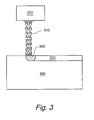
- Figure 3 illustrates a side-view of Zr-alloy 300 being treated with laser beam 310 generated by solid-state laser 370.
- Laser beam 310 moves from right to left in this exemplary illustration, it interacts with Zr-alloy 300 at location 360 and creates a layer 320.
- Layer 320 may, for example, be an altered microstructural surface layer or, alternatively or conjunctively, a surface oxide layer. If comprising a surface oxide layer, the thickness of layer 320 is preferably less than 25 micrometers, more preferably less than 20 micrometers, even more preferably less than 15 micrometers, even more preferably less than 10 micrometers, and most preferably less than 5 micrometers.
- FIG. 4 An example of a laser beam treated prototype test specimen is illustrated in Figure 4 .
- the specimen 400 was prepared from a flat Zircaloy-2 channel strip that was fabricated by a series of steps that are well-known to those skilled in the art.
- the strip fabrication steps included ingot melting, forging, and hot and cold rolling, a single intermediate beta quench, and multiple intermediate recrystallization anneals.
- a small portion of the strip was then machined from the strip to form test specimen 400.
- the small test specimen was then subjected to multiple, narrow, adjacent laser strikes 410 across the width of the test specimen which created a thin oxide layer and/or an altered microstructural surface layer corresponding to the position of the laser strikes.
- the laser strikes 410 were formed in air using a Lightwriter laser manufactured by Lumonics.
- the laser was a low power YAG-type rated at 25W. This is a continuous (as opposed to a pulsed) type laser and the barcode pattern (a code 39 barcode, which is well-known method of generating symbolic representations of alphanumeric characters) was generated through optics (i.e., rotating mirror, etc. rather than pulsing the laser or controlling beam shape).
- the laser is typically run at 80-85% of the rated power.
- the work piece is located at 8 inches from the YAG laser and it takes 7.5 seconds to make the 2-inch long bar code.
- test specimen was then placed into the core of a test reactor that simulated a commercial LWR aqueous reactor core environment.
- the test specimen was then extracted from the core and examined visually as indicated in Figure 4 .
- the laser strikes are observed as a bright linear mark in the central portion of the specimen against the light brownish background of the untreated portion of the test specimen.
- Some embodiments of the present invention may reduce shadow corrosion and may reduce the propensity for bowing interference between stainless steel control blade and Zr-based flow channel in a LWR.
- This interference may reduce a plant's safety margin and may lower plant efficiency when the cause is related to shadow corrosion.
- Factors that may cause the interference may include a differential hydrogen content that may be caused by differential shadow corrosion that may occur when the control blade is inserted and is in close proximity to the square channel on 2 of 4 sides, perhaps in combination with the well-known phenomenon of irradiation growth. Similar situations may develop when a dissimilar metal, such as an stainless steel instrument tube, is placed close to one corner of a Zr-alloy channel.
Landscapes
- Engineering & Computer Science (AREA)
- Physics & Mathematics (AREA)
- Chemical & Material Sciences (AREA)
- Mechanical Engineering (AREA)
- Crystallography & Structural Chemistry (AREA)
- Materials Engineering (AREA)
- Thermal Sciences (AREA)
- Metallurgy (AREA)
- Organic Chemistry (AREA)
- Manufacturing & Machinery (AREA)
- Plasma & Fusion (AREA)
- General Engineering & Computer Science (AREA)
- High Energy & Nuclear Physics (AREA)
- Laser Beam Processing (AREA)
- Heat Treatment Of Nonferrous Metals Or Alloys (AREA)
Abstract
Description
- The present invention generally relates to a nuclear boiling water reactor (BWR) and more specifically to treating the surface of a zirconium-alloy (Zr-alloy) fuel bundle material.
- BWRs generate power from a controlled nuclear fission reaction. As shown in
Figure 1 , a simplified BWR includes areactor chamber 101 that contains a nuclear fuel core and water. Generated steam is transferred throughpipe 102 toturbine 103, where electric power is generated, and the water returns to the core throughpipe 104. Acontrol computer 106 may control the operation of the BWR and particularly its core. - In the BWR core, fuel rod bundles are encased in thin rectangular fuel channels. A fuel channel may be embodied as a hollow box within which are arranged the fuel rod bundles. A particular problem with fuel channels is that they can deform. They may deform due to various nuclear and mechanical responses in the core of an operating BWR. Deformations may be partially affected by plant operation strategy. The nuclear and mechanical responses are complex and spread out over time. For example, the operation of a channel (the "cause") may result in channel deformation (the "effect") observed later in the residence time of the channel in the core.
-
Figure 2 schematically illustrates acontrol blade 12 and an associated fuel assembly, generally designated 13, comprised of fourfuel bundles 14. Thefuel bundles 14 are only partially illustrated with each bundle havingfuel rods 16, e.g., in a 10x10 array, and associated vertically spacedspacers 18 as is conventional, only onespacer 18 being illustrated in eachfuel bundle 14.Fuel channels 19 surround eachfuel bundle 14 and define a cruciform opening between the fuel assemblies. As will be appreciated,control blade 12 is cruciform in cross-section and is generally receivable within the core of the nuclear reactor in the cruciform openings between the fourfuel bundles 14, the blades being movable from below the fuel assemblies, i.e., withdrawn positions, to positions within the cruciform openings adjacent the fuel assemblies. - Interference between a fuel bundle channel and a control blade may be caused by bowing of Zircaloy (i.e., a zirconium-based alloy) flow channels due to side-side differences in channel hydrogen content. These differences may be caused by localized "shadow" corrosion, which may be caused by being in close proximity to stainless steel control blade on 2 of 4 channel sides. Irradiation growth - a common, well-known phenomenon that may be caused by exposure to differential neutron radiation gradients - may magnify and exacerbate the problem.
- The possible problem of shadow corrosion of Zr-based alloys has generally not been addressed adequately. There has been some work showing that an insulating coating on the non-Zr alloy component and modified blade materials may be effective in mitigation. Conceptually, beta absorbing coatings on the control blade and low Manganese (Mn) content materials have been proposed as solutions. Conventional methods to improve the uniform or nodular corrosion resistance through alloy composition control and metallurgical control through conventional heat treatment have generally not been effective in mitigating shadow corrosion, which appears to occur via a different mechanism. Likewise, extensive research related to hydrogen absorption into Zr-based alloys as a result of corrosion during operation in an light water reactor (LWR) may not have provided an entirely effective means of mitigating hydrogen absorption.
- Shadow corrosion may occur on Zircaloy fuel rods near Inconel (or other nickel-based superalloy) parts of a fuel bundle spacer - the spacer could be Zircaloy with Inconel springs or entirely Inconel - that contact the fuel rods. In severe instances the corrosion may even cause a fuel failure.
- At the present time, a laser bar code can be applied to each fuel rod in order to facilitate the identification and tracking of each fuel rod. This laser bar code may be applied to the full circumference of each fuel rod within a 3-inch band at one location. The bar code may generally consist of a series of discrete lines of thick and thin lines with spacing in between adjacent lines. To place this bar code onto each fuel rod, a narrow laser beam is typically used to create discrete, narrow lines. These bar codes, however, may not be substantially continuous (they are typically discrete), are generally only placed in close proximity to the spacer on part length fuel rods, and have generally not been placed on fuel channels.
- In an embodiment, the present invention generally relates to a method for treating a Zr-alloy fuel bundle material in a nuclear reactor. In an embodiment, the method includes treating a surface of the Zr-alloy fuel bundle material with a laser beam generated by a solid-state laser.
- In another embodiment, the present invention generally relates to a nuclear boiling water reactor that has a reactor chamber including a nuclear fuel core and water for generating steam and a turbine for generating electric power. In an embodiment, the reactor chamber includes a fuel rod bundle, which includes a fuel rod and a spacer. In an embodiment, the fuel rod bundle is made from a Zr-alloy whose surface has been subjected to a treatment by a laser beam generated by a YAG-based solid-state laser. In an embodiment, the treatment created a surface layer in the fuel rod bundle.
-
-
Figure 1 illustrates a simplified BWR including a reactor chamber that contains a nuclear fuel core and water; and -
Figure 2 illustrates an exemplary perspective view of a control rod and four fuel bundles with the control rod aligned with the cruciform openings between the fuel bundles. -
Figure 3 illustrates an exemplary side-view of a Zr-alloy being treated with a solid-state laser. -
Figure 4 illustrates a test specimen treated with a solid-state laser in accordance with an exemplary embodiment. - Embodiments of the present invention provide a method whereby the surface of the Zr-alloy fuel bundle material potentially susceptible to shadow corrosion is treated with a laser beam. This may reduce the propensity for shadow corrosion. If the Zr-alloy treated surface is a fuel channel placed in close proximity to a control blade, the likelihood of interference between the channel and control blade may be reduced. This, in turn, may improve the safe operation of the boiling water reactor. If the Zr-alloy treated surface is a fuel cladding placed in close proximity to a dissimilar fuel spacer material, the likelihood of enhanced spacer shadow corrosion and subsequent fuel failure may be reduced. The Zr-alloy may be, for example, Zircaloy-2, Zircaloy-4, or a niobium-containing Zr-alloy (such as a Zr-alloy containing 1-2% niobium (Nb)).
- According to an embodiment of the present invention, a laser beam may be used to treat substantially the entire continuous outer surface of the fuel channel material made from Zr-alloy. Alternatively, in another embodiment, a discontinuous surface of the fuel channel material is treated. A continuous, non-discrete treatment may be performed using a laser beam broad enough to cover and treat the entire surface in one pass per channel side, although a series of multiple adjacent and/or overlapping passes may also be suitable. For example, in certain embodiments, 10 or fewer passes may be utilized to treat the substantially continuous surface. Even more preferably, 5 or fewer passes may be utilized.
- The laser beam treatment may be performed during various stages of fabrication. According to an embodiment, the treatment may be performed during the early stages of fabrication. According to other embodiments, the treatment may be performed after the channel has been formed into a box, after it has been thermal size annealed, and/or after completion of substantially all surface grit blasting, etching, and polishing.
- In one embodiment, a laser beam treats or conditions at least a portion of the outer surface of the fuel cladding in a continuous or substantially continuous manner. The laser beam may treat either the entire outer surface or a more localized region, preferably one that is in close proximity to dissimilar spacer materials during operation of the nuclear reactor. A broad laser beam is preferably used to cover and treat the region of interest in a single pass or multiple passes. It should be noted that a narrow laser beam may be used, even if possibly necessitating a large number of passes before the entire region of interest is treated.
- Although the precise mechanism by which the laser treatment may mitigate shadow corrosion is not 6 fully known, it is believed that either (i) the local surface microstructure may be altered by the laser treatment (such as forming a beta quenched surface structure, altering the intermetallic particle size, or supersaturating the matrix with alloying elements that may normally have a low solubility) or (ii) the laser treatment may create a thin oxide layer that may reduce the rate of the electromechanical corrosion reaction that may occur in operation. Nevertheless, the operation of the present invention does not depend upon knowledge or recognition of the precise mechanism by which shadow corrosion may be mitigated.
- In some embodiments, the present invention may have a broader use than merely mitigating channel bowing. The laser treatment may also be applied to the outer surface of Zr-alloy fuel cladding to prevent shadow corrosion that may be caused by dissimilar metals (such as Inconel, for instance) used as spacers and/or spacer springs. Under susceptible conditions, enhanced spacer shadow corrosion may cause fuel cladding failures. In some embodiments, the present invention may prevent or at least reduce the likelihood of fuel failures.
- Extant laser beams may be used in certain embodiments of the present invention. The characteristics of the laser beam - including the power of the laser beam, its wavelength, its width, its speed, its depth of penetration into the Zr-alloy, the preferred temperature range of the Zr-alloy during treatment, the environment (e.g., composition of the atmosphere (such as air, argon, or other gasses), temperature, pressure, etc.) that the laser treatment is performed in, the cooling rate of the Zr-alloy material, etc. - may be varied according to and as required by operational conditions.
- Solid-state lasers may be used, including, for example, yttrium aluminum garnet-based (YAG-based) solid-state lasers. In YAG-based solid-state lasers, YAG may be doped with various elements or combinations of elements, including, for example, cerium(III) (Ce:YAG or YAG:Ce), chromium(IV) (Cr:YAG), dysprosium (Dy:YAG), erbium (Er:YAG), holmium (Ho:YAG), neodymium (Nd:YAG), samarium YAG (Sm:YAG), terbium (Tb:YAG), thulium (Tm:YAG), ytterbium (Yb:YAG), neodymium-cerium (Nd:Ce:YAG or Nd,Ce:YAG), holmium-chromium-thulium (Ho:Cr:Tm:YAG, or Ho,Cr,Tm:YAG). Other solid-state lasers may also be used, including, ruby solid-state lasers, glass-based solid-state lasers (such as neodymium glass (Nd:glass), ytterbium-doped glass, promethium 147 doped phosphate glass (147Pm+3:Glass), and erbium-doped and erbium-ytterbium codoped glass lasers), sapphire-based solid-state lasers (such as titanium-doped sapphire), neodymium YLF (Nd:YLF) solid-state laser, neodymium-doped YVO4 (Nd:YVO) solid-state laser, neodymium-doped yttrium calcium oxoborate (Nd:YCa4O(BO3)3 or Nd:YCOB), cerium-doped lithium strontium (or calcium) aluminum fluoride (Ce:LiSAF or Ce:LiCAF), chromium-doped chrysoberyl (alexandrite) solid-state laser, and other solid-state lasers. The solid-state lasers may be pulsed, continuous wave, or quasi-continuous wave.
-
Figure 3 illustrates a side-view of Zr-alloy 300 being treated withlaser beam 310 generated by solid-state laser 370. Aslaser beam 310 moves from right to left in this exemplary illustration, it interacts with Zr-alloy 300 atlocation 360 and creates alayer 320.Layer 320 may, for example, be an altered microstructural surface layer or, alternatively or conjunctively, a surface oxide layer. If comprising a surface oxide layer, the thickness oflayer 320 is preferably less than 25 micrometers, more preferably less than 20 micrometers, even more preferably less than 15 micrometers, even more preferably less than 10 micrometers, and most preferably less than 5 micrometers. - An example of a laser beam treated prototype test specimen is illustrated in
Figure 4 . Thespecimen 400 was prepared from a flat Zircaloy-2 channel strip that was fabricated by a series of steps that are well-known to those skilled in the art. The strip fabrication steps included ingot melting, forging, and hot and cold rolling, a single intermediate beta quench, and multiple intermediate recrystallization anneals. A small portion of the strip was then machined from the strip to formtest specimen 400. The small test specimen was then subjected to multiple, narrow, adjacent laser strikes 410 across the width of the test specimen which created a thin oxide layer and/or an altered microstructural surface layer corresponding to the position of the laser strikes. The laser strikes varied in size, such asthick strike 420 andthin strike 430. - The laser strikes 410 were formed in air using a Lightwriter laser manufactured by Lumonics. The laser was a low power YAG-type rated at 25W. This is a continuous (as opposed to a pulsed) type laser and the barcode pattern (a code 39 barcode, which is well-known method of generating symbolic representations of alphanumeric characters) was generated through optics (i.e., rotating mirror, etc. rather than pulsing the laser or controlling beam shape). The laser is typically run at 80-85% of the rated power. The work piece is located at 8 inches from the YAG laser and it takes 7.5 seconds to make the 2-inch long bar code.
- The test specimen was then placed into the core of a test reactor that simulated a commercial LWR aqueous reactor core environment. The test specimen was then extracted from the core and examined visually as indicated in
Figure 4 . The laser strikes are observed as a bright linear mark in the central portion of the specimen against the light brownish background of the untreated portion of the test specimen. - Some embodiments of the present invention may reduce shadow corrosion and may reduce the propensity for bowing interference between stainless steel control blade and Zr-based flow channel in a LWR. This interference may reduce a plant's safety margin and may lower plant efficiency when the cause is related to shadow corrosion. Factors that may cause the interference may include a differential hydrogen content that may be caused by differential shadow corrosion that may occur when the control blade is inserted and is in close proximity to the square channel on 2 of 4 sides, perhaps in combination with the well-known phenomenon of irradiation growth. Similar situations may develop when a dissimilar metal, such as an stainless steel instrument tube, is placed close to one corner of a Zr-alloy channel.
- It should be understood that all numbers and ranges disclosed and claimed herein are approximate.
- While the invention has been described in connection with what is presently considered to be the most practical and preferred embodiment, it is to be understood that the invention is not to be limited to the disclosed embodiment, but on the contrary, is intended to cover various modifications and equivalent arrangements included within the scope of the appended claims.
Claims (10)
- A method for treating a Zr-alloy fuel bundle material 300) for use in a nuclear reactor (101) comprising the Zr-alloy fuel bundle material (300), the method comprising the step of treating a surface of the Zr-alloy fuel bundle material (300) with a laser beam (310) generated by a solid-state laser.
- The method of claim 1, wherein the step of treating the surface of the Zr-alloy fuel bundle material (300) occurs in 5 or fewer passes.
- The method of claim 1 or claim 2, wherein the surface of the Zr-alloy fuel bundle material (300) comprises a localized region located in close proximity to a spacer (18) during operation of the nuclear reactor (101).
- The method of any preceding claim, wherein the step of treating the surface of the Zr-alloy fuel bundle material (300) causes a reduction in a generation of shadow corrosion occurring during operation of the nuclear reactor (101).
- The method of any preceding claim, wherein the step of treating the surface of the Zr-alloy fuel bundle material (300) causes a reduction of interference between a control blade (12) and a flow channel (19) occurring during operation of the nuclear reactor (101).
- The method of any preceding claim, wherein the step of treating the surface of the Zr-alloy fuel bundle material (300) creates a layer (320) comprising an altered microstructural surface layer.
- The method of any preceding claim, wherein the step of treating the surface of the Zr-alloy fuel bundle material (300) creates a layer (320) comprising a surface oxide layer.
- The method of claim 7, wherein the surface oxide layer has a thickness less than 15 micrometers.
- The method of any preceding claim, wherein the solid-state laser comprises a YAG-based solid-state laser.
- A nuclear boiling water reactor comprising:a reactor chamber (101) comprising a nuclear fuel core and water for generating steam; anda turbine (103) for generating electric power;wherein the reactor chamber (101) comprises a fuel rod bundle (14) comprising a fuel rod (16) and a spacer (18);
wherein the fuel rod bundle (14) comprises Zr-alloy; and
wherein a surface of the fuel rod bundle (14) was subjected to a treatment by a laser beam (310) generated by a YAG-based solid-state laser; and
wherein the treatment created a surface layer (320) in the fuel rod bundle.
Applications Claiming Priority (1)
| Application Number | Priority Date | Filing Date | Title |
|---|---|---|---|
| US11/611,348 US20110180184A1 (en) | 2006-12-15 | 2006-12-15 | Surface laser treatment of zr-alloy fuel bundle material |
Publications (2)
| Publication Number | Publication Date |
|---|---|
| EP1933328A2 true EP1933328A2 (en) | 2008-06-18 |
| EP1933328A3 EP1933328A3 (en) | 2010-11-10 |
Family
ID=39146874
Family Applications (1)
| Application Number | Title | Priority Date | Filing Date |
|---|---|---|---|
| EP07122212A Ceased EP1933328A3 (en) | 2006-12-15 | 2007-12-04 | Surface laser treatment of zr-alloy fuel bundle material |
Country Status (4)
| Country | Link |
|---|---|
| US (1) | US20110180184A1 (en) |
| EP (1) | EP1933328A3 (en) |
| JP (1) | JP2008151788A (en) |
| TW (1) | TW200848546A (en) |
Cited By (2)
| Publication number | Priority date | Publication date | Assignee | Title |
|---|---|---|---|---|
| EP2178092A3 (en) * | 2008-10-14 | 2013-10-30 | Global Nuclear Fuel-Americas, LLC | Fuel rod assembly and method for mitigating the radiation-enhanced corrosion of a zirconium-based component |
| US9490036B2 (en) | 2010-04-19 | 2016-11-08 | Westinghouse Electric Sweden Ab | Control rod |
Families Citing this family (1)
| Publication number | Priority date | Publication date | Assignee | Title |
|---|---|---|---|---|
| US11440135B2 (en) * | 2013-05-23 | 2022-09-13 | Trumpf Werkzeugmaschinen Gmbh + Co. Kg | Laser machining nozzle for a laser machining device, and laser machining device |
Citations (2)
| Publication number | Priority date | Publication date | Assignee | Title |
|---|---|---|---|---|
| EP0614195A1 (en) | 1993-03-02 | 1994-09-07 | Westinghouse Electric Corporation | Fret resistant fuel rod with zirconium oxide layer |
| FR2774801A1 (en) | 1998-02-09 | 1999-08-13 | Cogema | Nuclear fuel rod cladding decontamination using pulsed laser beam |
Family Cites Families (8)
| Publication number | Priority date | Publication date | Assignee | Title |
|---|---|---|---|---|
| US3088893A (en) * | 1960-08-31 | 1963-05-07 | Gen Electric | Malleable tube-clad article and manufacturing method therefor |
| US4294631A (en) * | 1978-12-22 | 1981-10-13 | General Electric Company | Surface corrosion inhibition of zirconium alloys by laser surface β-quenching |
| US4279667A (en) * | 1978-12-22 | 1981-07-21 | General Electric Company | Zirconium alloys having an integral β-quenched corrosion-resistant surface region |
| US5236524A (en) * | 1992-01-21 | 1993-08-17 | The Babcock & Wilcox Company | Method for improving the corrosion resistance of a zirconium-based material by laser beam |
| US5333161A (en) * | 1993-03-19 | 1994-07-26 | General Electric Company | Intergranular stress corrosion cracking mitigation by rapid quench melting |
| US5844959A (en) * | 1997-08-01 | 1998-12-01 | Siemens Power Corporation | Zirconium niobium tin alloys for nuclear fuel rods and structural parts for high burnup |
| US6259756B1 (en) * | 2000-08-22 | 2001-07-10 | General Electric Company | Control blade sequence patterns for optimization of BWR power control |
| US20060203952A1 (en) * | 2005-03-14 | 2006-09-14 | General Electric Company | Methods of reducing hydrogen absorption in zirconium alloys of nuclear fuel assemblies |
-
2006
- 2006-12-15 US US11/611,348 patent/US20110180184A1/en not_active Abandoned
-
2007
- 2007-12-03 TW TW096145925A patent/TW200848546A/en unknown
- 2007-12-04 EP EP07122212A patent/EP1933328A3/en not_active Ceased
- 2007-12-13 JP JP2007321508A patent/JP2008151788A/en active Pending
Patent Citations (2)
| Publication number | Priority date | Publication date | Assignee | Title |
|---|---|---|---|---|
| EP0614195A1 (en) | 1993-03-02 | 1994-09-07 | Westinghouse Electric Corporation | Fret resistant fuel rod with zirconium oxide layer |
| FR2774801A1 (en) | 1998-02-09 | 1999-08-13 | Cogema | Nuclear fuel rod cladding decontamination using pulsed laser beam |
Cited By (4)
| Publication number | Priority date | Publication date | Assignee | Title |
|---|---|---|---|---|
| EP2178092A3 (en) * | 2008-10-14 | 2013-10-30 | Global Nuclear Fuel-Americas, LLC | Fuel rod assembly and method for mitigating the radiation-enhanced corrosion of a zirconium-based component |
| US8792607B2 (en) | 2008-10-14 | 2014-07-29 | General Electric Company | Fuel rod assembly and method for mitigating the radiation-enhanced corrosion of a zirconium-based component |
| US9805831B2 (en) | 2008-10-14 | 2017-10-31 | General Electric Company | Fuel rod assembly and method for mitigating the radiation-enhanced corrosion of a zirconium-based component |
| US9490036B2 (en) | 2010-04-19 | 2016-11-08 | Westinghouse Electric Sweden Ab | Control rod |
Also Published As
| Publication number | Publication date |
|---|---|
| US20110180184A1 (en) | 2011-07-28 |
| TW200848546A (en) | 2008-12-16 |
| JP2008151788A (en) | 2008-07-03 |
| EP1933328A3 (en) | 2010-11-10 |
Similar Documents
| Publication | Publication Date | Title |
|---|---|---|
| JP2638351B2 (en) | Fuel assembly | |
| EP0488027B2 (en) | Method of manufacturing a zirconium based alloy fuel channel box | |
| JP3373638B2 (en) | Laser peening method | |
| KR100461017B1 (en) | Method for preparing niobium-containing zirconium alloys for nuclear fuel cladding tubes having the excellent corrosion resistance | |
| ES2202235T3 (en) | CIRCONIO-NIOBIO-TIN ALLOYS FOR NUCLEAR FUEL BARS AND STRUCTURAL PARTS FOR A HIGH GRADE OF COMBUSTION. | |
| Johnston et al. | Nickel-ion bombardment of annealed and cold-worked type 316 stainless steel | |
| Elkin et al. | Pulsed laser welding of Zr1% Nb alloy | |
| US8958523B2 (en) | Spacer grid | |
| EP0908897B1 (en) | Zirconium tin iron alloys for nuclear fuel rods and structural parts for high burnup | |
| JPH08260081A (en) | Corrosion resistant zirconium alloys for long life fuel cladding | |
| US5188676A (en) | Method for annealing zircaloy to improve nodular corrosion resistance | |
| JP2008151788A (en) | SURFACE LASER TREATMENT FOR Zr-ALLOY FUEL BUNDLE MATERIAL | |
| JPH06289171A (en) | Fuel assembly, its nuclear fuel rod cladding, and method for strengthening nuclear fuel rods | |
| EP0795618B1 (en) | Zirconium based alloy of low irradiation growth, method of producing the same, and use of the same | |
| US8116422B2 (en) | LWR flow channel with reduced susceptibility to deformation and control blade interference under exposure to neutron radiation and corrosion fields | |
| JP2814981B2 (en) | Fuel assembly | |
| EP1634973A1 (en) | Method of manufacturing a nuclear reactor component in zirconium alloy | |
| JP3492881B2 (en) | Fuel channel box and fuel assembly | |
| JP3424452B2 (en) | Fuel assembly, fuel channel box used therefor, and method of manufacturing the same | |
| JP3191813B2 (en) | Fuel channel box, fuel assembly and method of use | |
| EP1408129A1 (en) | Zirconium-base alloy and nuclear reactor component comprising the same | |
| JP2001074872A (en) | Method for producing zirconium alloy for nuclear reactor | |
| JPH05323070A (en) | Channel box | |
| Petel'guzov | Corrosion of Zr+ 2.5% Nb Alloy Hardened by Thermal and Thermomechanical Treatment | |
| JPH04136787A (en) | Corrosion-resistant zirconium base alloy and preparation thereof |
Legal Events
| Date | Code | Title | Description |
|---|---|---|---|
| PUAI | Public reference made under article 153(3) epc to a published international application that has entered the european phase |
Free format text: ORIGINAL CODE: 0009012 |
|
| AK | Designated contracting states |
Kind code of ref document: A2 Designated state(s): AT BE BG CH CY CZ DE DK EE ES FI FR GB GR HU IE IS IT LI LT LU LV MC MT NL PL PT RO SE SI SK TR |
|
| AX | Request for extension of the european patent |
Extension state: AL BA HR MK RS |
|
| PUAL | Search report despatched |
Free format text: ORIGINAL CODE: 0009013 |
|
| AK | Designated contracting states |
Kind code of ref document: A3 Designated state(s): AT BE BG CH CY CZ DE DK EE ES FI FR GB GR HU IE IS IT LI LT LU LV MC MT NL PL PT RO SE SI SK TR |
|
| AX | Request for extension of the european patent |
Extension state: AL BA HR MK RS |
|
| 17P | Request for examination filed |
Effective date: 20110510 |
|
| AKX | Designation fees paid |
Designated state(s): CH DE ES FI LI SE |
|
| 17Q | First examination report despatched |
Effective date: 20111027 |
|
| STAA | Information on the status of an ep patent application or granted ep patent |
Free format text: STATUS: THE APPLICATION HAS BEEN REFUSED |
|
| 18R | Application refused |
Effective date: 20130317 |