EP1933156A1 - Zero-phase current detecting apparatus - Google Patents
Zero-phase current detecting apparatus Download PDFInfo
- Publication number
- EP1933156A1 EP1933156A1 EP06797155A EP06797155A EP1933156A1 EP 1933156 A1 EP1933156 A1 EP 1933156A1 EP 06797155 A EP06797155 A EP 06797155A EP 06797155 A EP06797155 A EP 06797155A EP 1933156 A1 EP1933156 A1 EP 1933156A1
- Authority
- EP
- European Patent Office
- Prior art keywords
- zero
- unit
- phase
- detecting apparatus
- phase current
- Prior art date
- Legal status (The legal status is an assumption and is not a legal conclusion. Google has not performed a legal analysis and makes no representation as to the accuracy of the status listed.)
- Withdrawn
Links
Images




Classifications
-
- G—PHYSICS
- G01—MEASURING; TESTING
- G01R—MEASURING ELECTRIC VARIABLES; MEASURING MAGNETIC VARIABLES
- G01R19/00—Arrangements for measuring currents or voltages or for indicating presence or sign thereof
- G01R19/175—Indicating the instants of passage of current or voltage through a given value, e.g. passage through zero
Definitions
- the present invention generally relates to a zero-phase current detecting apparatus.
- the present invention specifically relates to a zero-phase current detecting apparatus in which a zero-phase-sequence current transformer is used.
- a Zero-phase-sequence Current Transformer is a device that detects a zero-phase current flowing in an electric power line inserted through its own detection core.
- a ZCT is used, for example, in switchboards, electrical devices and the like, as a detector that detects a ground-fault current caused by a ground fault.
- Patent Documents 1 and 2 are examples of documents that disclose a current detecting apparatus and the like in which a ZCT is used.
- Patent Document 1 discloses a direct-current ground-fault detecting apparatus that detects a ground fault of a direct current at a low cost with a high level of precision thereby ensuring a high level of safety.
- Patent Document 2 discloses a direct-current ground-fault current detecting circuit that accurately detects whether a direct-current ground-fault current has generated or accurately detects a direct-current value at a given moment without being influenced by the hysteresis characteristics of a ZCT.
- Patent Document 1 Japanese Patent Application Laid-open No. 2004-153991
- Patent Document 2 Japanese Patent Application Laid-open No. 2005-065382
- a detection output from the ZCT is corrected based on a detection output from a temperature sensor that detects an atmospheric temperature near the ZCT. Accordingly, it is necessary to modify data used in the correction process depending on the type and the model of the ZCT being used and also to store, in advance, the data used in the correction process into a storage device such as a ROM. Consequently, this direct-current ground-fault detecting apparatus has a problem in that the mode of control for detecting a zero-phase current with a high level of precision becomes complicated, and the costs of designing and manufacturing the detecting apparatus become high.
- the detecting circuit detects a current that flows on the secondary side of the ZCT (the side on which a detection coil wound around a detection core included in the ZCT is positioned; hereinafter, “the secondary side”) by causing an offset current to flow on the primary side of the ZCT (the side on which the electric power line inserted through the detection core is positioned; hereinafter, “the primary side”).
- the primary side the side on which the electric power line inserted through the detection core is positioned
- This invention has been made in view of the above. It is an object of the present invention to provide a zero-phase current detecting apparatus in which a ZCT is used and that makes it possible to prevent degradation in the level of precision in the detection process without increasing the costs.
- a zero-phase current detecting apparatus comprising a zero-phase-sequence current transformer that includes a detection coil and is operable to detect, via the detection coil, a zero-phase current flowing in an electric power line inserted through the zero-phase-sequence current transformer, includes a pulse generating unit that applies an excitation pulse signal to one end of the detection coil included in the zero-phase-sequence current transformer; a current detecting unit that is connected to other end of the detection coil and converts a current flowing via the detection coil into a voltage output; a peak detecting unit that detects a peak value of the output voltage output from the current detecting unit; an adding unit that outputs a difference value between a predetermined target value and the peak value; and a current regulating unit that regulates the current flowing in the detection coil based on an output of the adding unit, wherein a feedback loop is made up of the current detecting unit, the peak detecting unit, the adding unit, and the current regulating unit, and the
- a feedback loop is made up of the current detecting unit, the peak detecting unit, the adding unit, and the current regulating unit.
- a zero-phase current is detected based on an output of the adding unit obtained when an output of the peak detecting unit is regulated so as to be equal to the target value under the control of the feedback loop.
- Fig. 1 is a functional block diagram of a zero-phase current detecting apparatus according to a first embodiment of the present invention.
- the zero-phase current detecting apparatus according to the first embodiment is configured so as to include a zero-phase-sequence current transformer ZCT, a pulse generating unit 11, a current detecting unit 12, a peak detecting unit 15, an adding unit 18, and a current regulating unit 20.
- an electric power line 10 which is a detection target for detecting whether a zero-phase current flows in it, is inserted through the zero-phase-sequence current transformer ZCT.
- the zero-phase-sequence current transformer ZCT includes a detection coil 14 that is wound around a detection core.
- the pulse generating unit 11 is connected to one end of the detection coil 14.
- the current detecting unit 12 is connected to the other end of the detection coil 14.
- the output of the current detecting unit 12 serves as an input signal to the peak detecting unit 15.
- the output of the peak detecting unit 15 serves as an input signal to the adding unit 18.
- a predetermined target value 25 is input to the adding unit 18.
- An output of the adding unit 18 is configured into an output terminal ("OUT PUT") 26 of the zero-phase current detecting apparatus according to this embodiment and also serves as an input signal to the current regulating unit 20.
- the output of the current regulating unit 20 is input to an input terminal of the current detecting unit 12 while acting on the current detecting unit 12 or the detection coil 14.
- a feedback loop is made up of the current detecting unit 12, the peak detecting unit 15, the adding unit 18, and the current regulating unit 20, and the output of the adding unit 18 is output from the output terminal 26 as the output of the zero-phase current detecting apparatus.
- Fig. 2 is a diagram of an exemplary circuit configuration of the zero-phase current detecting apparatus according to the first embodiment of the present invention to materialize the functional configuration shown in Fig. 1 .
- a pulse generator 11a corresponds to the pulse generating unit 11 shown in Fig. 1 .
- a current detector 12a corresponds to the current detecting unit 12 and the current regulating unit 20.
- a peak detecting circuit 15a corresponds to the peak detecting unit 15.
- a proportional integral controller 21 corresponds to the adding unit 18.
- a target value output circuit 25a corresponds to the target value 25. It is possible to configure the current detector 12a by using a single resistor 12b, as shown in the drawing.
- the peak detecting circuit 15a by combining circuit elements such as an operational amplifier, a resistor, a capacitor, and a diode, as shown in the drawing. It is possible to configure the target value output circuit 25a by using, for example, two resistors, as shown in the drawing. It is possible to configure the proportional integral controller 21 by combining circuit elements such as an operational amplifier, a resistor, and a capacitor, as shown in the drawing. In this manner, the current detector 12a has the function of the current regulating unit 20, in addition to the function of the current detecting unit 12. The details of the functions of the current detector 12a will be explained later.
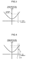
- Figs. 3 and 4 are graphs for explaining a relationship between a current that flows in the detection coil 14 and an output voltage of the peak detecting circuit 15a.
- Fig. 3 a situation in which no zero-phase current is flowing in the electric power line 10 is shown.
- Fig. 4 a situation in which a zero-phase current is flowing in the electric power line 10 is shown.
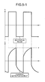
- Fig. 5-1 is an output waveform of the current detector 12a in a situation where no zero-phase current is flowing.
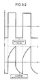
- Fig. 5-2 is an output waveform of the current detector 12a in a situation where a zero-phase current is flowing.
- an excitation pulse signal generated by the pulse generator 11a is input to one end of the detection coil 14 included in the zero-phase-sequence current transformer ZCT through which the electric power line 10 is inserted.
- the detection core (not shown) of the zero-phase-sequence current transformer ZCT is in an excited state.
- a zero-phase current flowing in the electric power line 10 is detected by the detection coil 14.
- the current detector 12a connected to the zero-phase-sequence current transformer ZCT converts the current flowing in the detection coil 14 into a voltage.
- the voltage output from the current detector 12a is input to the peak detecting circuit 15a.
- the peak detecting circuit 15a detects a peak value of the output of the current detector 12a and outputs the detected peak value.
- the output of the peak detecting circuit 15a is input to one of input terminals (i.e., the reversal input terminal) of the proportional integral controller 21.
- a target value ⁇ set by the target value output circuit 25a is input to the other of the input terminals (i.e., the non-reversal input terminal) of the proportional integral controller 21.
- the proportional integral controller 21 performs a proportional integral computation by using the difference between the target value ⁇ and the output of the peak detecting circuit 15a as an input signal.
- a proportional integral output is input to the current detector 12a.
- the current detector 12a converts the current flowing in the detection coil 14 into a voltage and outputs the voltage.
- the current detector 12a has the function to detect the current flowing in the zero-phase-sequence current transformer ZCT.
- the output of the proportional integral controller 21 is connected to a terminal (a second end) of the resistor 12b that is different from a connection terminal (a first end) being connected to the detection coil 14 included in the zero-phase-sequence current transformer ZCT.
- the output of the proportional integral controller 21 has an action to change the electric potential of the second end side of the resistor 12b that is used as a reference for the output of the current detector 12a (i.e., the output to the peak detecting circuit 15a). It is also acceptable to consider that this action is caused by a decrease in the voltage detected by the current detector 12a because a current that corresponds to the output of the proportional integral controller 21 flows toward the pulse generator 11a via the detection coil 14. In any case, the current detector 12a also has the current regulating function to regulate the current flowing in the detection coil 14, as shown in the functional diagram in Fig. 1 . It is also acceptable to consider that this current regulating function is realized by collaboration between the current detector 12a and the proportional integral controller 21 shown in Fig. 2 .
- a feedback loop is made up of the current detector 12a, the peak detecting circuit 15a, the target value output circuit 25a, and the proportional integral controller 21.
- the difference between the output of the peak detecting circuit 15a and the target value ⁇ is subjected to feedback control by the feedback loop and regulated so that the output of the peak detecting circuit 15a is always equal to the target value ⁇ .
- Fig. 3 The state in this situation is shown in Fig. 3 .
- the vertical axis shows the voltage output from the peak detecting circuit 15a
- the horizontal axis shows the current flowing in the current detector 12a (the detection coil 14).
- the current flows taking a course as follows: the proportional integral controller 21 ⁇ the current detector 12a ⁇ the zero-phase-sequence current transformer ZCT.
- This situation is the same as a state in which a zero-phase current I 0 is equivalently flowing in the electric power line 10.
- the output of the peak detecting circuit 15a is always constant regardless of the level of the zero-phase current flowing in the electric power line 10.
- the zero-phase current flowing in the electric power line 10 is offset by a compensating current (having the same level as ⁇ I and being in a direction opposite to the direction of ⁇ I) that is caused to flow in the zero-phase-sequence current transformer ZCT by a change in the output of the current detector 12a.
- the current that flows in the detection coil is constant and remains to be I 0 . Consequently, the flux in the detection core included in the zero-phase-sequence current transformer ZCT is maintained to be constant.
- the voltage output from the current detector 12a i.e., the voltage output from the present apparatus will be explained.
- the output waveform of the current detector 12a changes according to the excitation pulse signal generated by the pulse generator 11a in the manner shown in the lower half of Fig. 5-1 .
- the peak detecting circuit 15a detects a peak value ⁇ of the output of the current detector.
- the current flowing in the detection coil 14 maintains the constant value, as explained above; however, the electric potential at the other end of the current detector 12a, i.e., the output of the current detector 12a, changes as shown in Fig. 5-2 .
- the value of ⁇ is positively correlated with the level of the zero-phase current flowing in the electric power line 10. Accordingly, it is possible to output the value of the zero-phase current flowing in the electric power line 10, based on a difference between the value of ⁇ and the value of ⁇ .
- Fig. 6 is a graph for explaining the detection characteristic of the peak detecting circuit 15a.
- the detection characteristic of the peak detecting circuit 15a have linearity in the area K1 in the drawing.
- the detection characteristic of the peak detecting circuit 15a is non-linear in the area K2 in the drawing.
- the target value ⁇ being output by the target value output circuit 25a it is desirable to set the target value ⁇ being output by the target value output circuit 25a to be at such a level that the output of the peak detecting circuit 15a keeps its linearity. By setting the target value ⁇ at such a level, it is possible to detect the zero-phase current with a high level of precision.
- the proportional integral controller 21 shown in Fig. 2 is used as the adding unit 18 shown in Fig. 1 .
- the gain of the proportional integral controller 21 is not so large, it is acceptable to use a proportional controller that includes no capacitor in the feedback portion.
- Fig. 7 is a functional block diagram of a zero-phase current detecting apparatus according to a second embodiment of the present invention.
- the zero-phase current detecting apparatus according to the second embodiment, the configuration of the zero-phase current detecting apparatus shown in Fig. 1 is used as the base.
- the zero-phase current detecting apparatus further includes a control polarity reversal preventing unit 30 provided between the adding unit 18 and the current regulating unit 20.
- the control polarity reversal preventing unit 30 has a function (called an operation range limiting function) to prevent the operating point of the peak detecting unit 15 from going out of a control range so that the detection core included in the zero-phase-sequence current transformer ZCT does not become saturated.
- Fig. 8 is a graph for explaining the function of the control polarity reversal preventing unit 30.
- the output of the peak detecting unit 15 when the output of the peak detecting unit 15 is larger than the target value Y, the output of the peak detecting unit 15 changes so as to become equal to the target value ⁇ . This situation is equivalent to a situation obtained when a negative zero-phase current is caused to flow in the zero-phase-sequence current transformer ZCT.
- the output of the peak detecting unit 15 is smaller than the target value ⁇ , the output of the peak detecting unit 15 changes so as to equal to the target value ⁇ . This situation is equivalent to a situation obtained when a positive zero-phase current is caused to flow in the zero-phase-sequence current transformer ZCT.
- control polarity reversal preventing unit 30 is provided between the adding unit 18 and the current regulating unit 20.
- Fig. 9 is a diagram of an exemplary circuit configuration of the zero-phase current detecting apparatus according to the second embodiment of the present invention to materialize the functional configuration shown in Fig. 7 .
- a control polarity reversal preventing circuit 30a is provided as a constituent element that corresponds to the control polarity reversal preventing unit 30 shown in Fig. 7 . It is possible to configure the control polarity reversal preventing circuit 30a by combining circuit elements such as an operational amplifier and a diode as shown in the drawings.
- Other constituent elements are the same as the ones in the circuit configuration shown in Fig. 2 . Those constituent elements will be referred to by using the same reference characters, and the explanation thereof will be omitted.
- the output of the proportional integral controller 21 serves an input signal to the control polarity reversal preventing circuit 30a and is input to a non-reversal input terminal of the operational amplifier.
- the non-reversal input terminal of the operational amplifier is connected to a ground via the diode.
- Fig. 10 is a functional block diagram of a zero-phase current detecting apparatus according to a third embodiment of the present invention.
- the configuration of the zero-phase current detecting apparatus shown in Fig. 1 is used as the base.
- the zero-phase current detecting apparatus further includes a magnetization forcing unit 32 that acts on the current detecting unit 12 or the detection coil 14.
- the magnetization forcing unit 32 has a function to exercise control so that the detection core included in the zero-phase-sequence current transformer ZCT is in a predetermined magnetized state.
- Fig. 11 is a graph for explaining the function of the magnetization forcing unit 32.
- the current regulating unit 20 operates so as to exercise control in such a manner that the current flowing in the detection coil is constant.
- the magnetic flux within the detection core included in the zero-phase-sequence current transformer ZCT changes.
- the magnetized state of the detection core also changes. If the magnetized state of the detection core changes, the output characteristic of the peak detecting unit 15 changes, for example, from the one shown with a broken line to the one shown with a solid line, as shown in Fig. 11 .
- the level of precision in the detection process is lowered.
- the magnetization forcing unit 32 that acts on the current detecting unit 12 or the detection coil 14 is provided, as explained above.
- Fig. 12 is a diagram of an exemplary circuit configuration of the zero-phase current detecting apparatus according to the third embodiment of the present invention to materialize the functional configuration shown in Fig. 10 .
- the control polarity reversal preventing circuit 30a shown in Fig. 9 is also provided at the same time. However, needless to say, it is acceptable to use a configuration in which the control polarity reversal preventing circuit 30a is not included.
- a magnetization forcing circuit 32a and a magnetization instruction generator 32b that controls the magnetization forcing circuit 32a are provided as constituent elements that correspond to the magnetization forcing unit 32 shown in Fig. 10 . It is possible to configure the magnetization forcing circuit 32a by combining circuit elements such as a transistor and a resistor as shown in the drawing. It is possible to configure the magnetization instruction generator 32b by using a digital processor such as a microcomputer. Other constituent elements are the same as the ones in the circuit configuration shown in Fig. 9 . Those constituent elements will be referred to by using the same reference characters, and the explanation thereof will be omitted.
- the magnetization forcing circuit 32a brings the current flowing in the detection coil 14 into the magnetization forcing circuit 32a (when I 1 >0) or sends a current into the detection coil 14 (when I 1 ⁇ 0), based on the control of the magnetization instruction generator 32b.
- the magnetization instruction generator 32b exercises control so that the magnetized state of the detection core included in the zero-phase-sequence current transformer ZCT maintains a predetermined state (for example, the state obtained at a reference point in time) by regulating the magnetizing current I 1 that is caused to flow in the detection coil 14 via the magnetization forcing circuit 32a.
- the zero-phase current detecting apparatus because the magnetized state of the detection core included in the zero-phase-sequence current transformer ZCT is stabilized, changes in the output characteristic of the peak detecting unit 15 are inhibited. Thus, it is possible to detect the current with a high level of precision, without receiving any influence from external magnetizing factors.
- magnetization instruction generator 32b it is acceptable to configure the magnetization instruction generator 32b by using a controller other than a microcomputer. It should be noted, however, that by configuring the magnetization instruction generator 32b by using a microcomputer, it is possible to exercise control in a finely-tuned manner with regard to magnetization instructions (e.g. magnetization periods and magnetization timing) and the like. Thus, it is possible to detect the current with an even higher level of precision.
- magnetization instructions e.g. magnetization periods and magnetization timing
- the magnetizing current I 1 that is caused to flow in the detection coil 14 is regulated via the magnetization forcing circuit 32a; however, another arrangement is also acceptable in which a secondary coil (i.e., a magnetization control coil) that is different from the detection coil 14 is provided so that the magnetizing current I 1 is caused to flow in the magnetization control coil.
- a secondary coil i.e., a magnetization control coil
- the current level proportional to the ratio of the number of turns of the coil is considered to be equivalent to the level of a current flowing through the detection core included in the zero-phase-sequence current transformer ZCT.
- the current used in the magnetization control it is possible to make the current used in the magnetization control smaller.
- the zero-phase current detecting apparatus when the method in which a current is caused to flow on the primary side of the zero-phase-sequence current transformer ZCT is used, it is also possible to use a general-purpose zero-phase-sequence current transformer ZCT. Thus, it is possible to configure the zero-phase current detecting apparatus at a low cost.
- the zero-phase current detecting apparatus according to the fourth embodiment is characterized in that it provides a control method to maintain detection performances with an even higher level of precision by appropriately controlling the magnetizing current applied to the detection core included in the zero-phase-sequence current transformer ZCT so as to prevent the detection core included in the zero-phase-sequence current transformer ZCT from becoming saturated.
- the zero-phase current detecting apparatus according to the fourth embodiment may have a configuration similar to that of the zero-phase current detecting apparatus according to the third embodiment.
- the detection core included in the zero-phase-sequence current transformer ZCT may become saturated, depending on the current amount of the magnetizing current that is forcibly caused to flow. In such a situation, it is difficult to detect a zero-phase current. Accordingly, to prevent the detection core included in the zero-phase-sequence current transformer ZCT from becoming saturated, it is necessary to control the current amount of the magnetizing current so as to be at an appropriate level.
- magnetizing operation For example, it is desirable to continuously perform an operation to cause a magnetizing pulse current to flow (hereinafter, "magnetizing operation") for a short period of time.
- magnetizing operation By exercising control this way, it is possible to prevent the detection core included in the zero-phase-sequence current transformer ZCT from becoming saturated and to perform the detection process with an even higher level of precision.
- the magnetizing pulse current when the magnetizing operation is continuously performed for a short period of time as described above, it is desirable to cause the magnetizing pulse current to flow in synchronization with an excitation pulse.
- the state of the magnetic flux of the detection core included in the zero-phase-sequence current transformer ZCT during a cycle period in which the magnetizing operation is performed is different from the state of the magnetic flux during a cycle period in which no magnetizing operation is performed.
- the output of the peak detecting circuit is not stable.
- the magnetizing operation is performed in synchronization with the excitation pulse, it is possible to stabilize the operation of the peak detecting circuit.
- the length of the period in which the magnetizing operation is performed for a short period of time is equal to or shorter than 20% of the excitation cycle period (more preferably, equal to or shorter than 5% of the excitation cycle period) and also so that one output is made in every excitation cycle period.
- Fig. 14 is a functional block diagram of a zero-phase current detecting apparatus according to a fifth embodiment of the present invention.
- the configuration of the zero-phase current detecting apparatus shown in Fig. 1 is used as the base.
- the zero-phase current detecting apparatus further includes a high frequency passing unit 34 provided between the adding unit 18 and the output terminal 26.
- the high frequency passing unit 34 has a function to filter an output fluctuation caused by a temperature characteristic of the zero-phase-sequence current transformer ZCT.
- Other configurations of the zero-phase current detecting apparatus according to the fifth embodiment are the same as or similar to the configuration of the zero-phase current detecting apparatus according to the first embodiment shown in Fig. 1 .
- the constituent elements in the same or similar configurations will be referred to by using the same reference characters, and the explanation thereof will be omitted.
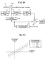
- Fig. 15 is a graph of an example of the temperature characteristic of the zero-phase-sequence current transformer ZCT.
- the vertical axis shows the detection output of the zero-phase-sequence current transformer ZCT, while the horizontal axis shows the zero-phase current.
- the output of zero-phase-sequence current transformer ZCT largely fluctuates, depending on changes in the ambient temperature thereof. Thus, the level of precision in the process to detect the zero-phase current can be lowered.
- the high frequency passing unit 34 is provided between the adding unit 18 and the output terminal 26, as shown in Fig. 14 .
- the changes in the detection output of the zero-phase-sequence current transformer ZCT are determined by a time constant for the changes in the ambient temperature.
- the time constant is sufficiently larger than a time required to perform the zero-phase current detection.
- the time constant of the high frequency passing unit 34 is arranged to be a short period of time, there is a higher possibility that a change in the output caused by detection of a zero-phase current and a change in the output caused by a change in the ambient temperature are erroneously detected.
- the time constant of the high frequency passing unit 34 is equal to or longer than 10 seconds, it is possible to detect a component that has a frequency equal to or higher than 0.016 hertz (Hz), out of the detection output of the peak detecting unit.
- Hz hertz
- the time constant of the high frequency passing unit 34 is, for example, equal to or longer than 1 minute, or equal to or longer than 20 minutes.
- the magnetization forcing unit 32 it is possible to configure the high frequency passing unit 34 by using a microcomputer.
- the high frequency passing unit 34 is configured by using a microcomputer, there is no need to provide a filtering circuit.
- the example has been explained in which the configuration including the high frequency passing unit 34 provided between the adding unit 18 and the output terminal 26 is applied to the zero-phase current detecting apparatus according to the first embodiment shown in Fig. 1 .
- Fig. 16 is a functional block diagram of a zero-phase current detecting apparatus according to a sixth embodiment of the present invention.
- the zero-phase current detecting apparatus according to the sixth embodiment further includes a time constant changing unit 36 that is operable to change the time constant of the high frequency passing unit 34, in addition to the configuration of the zero-phase current detecting apparatus shown in Fig. 14 .
- Other configurations of the zero-phase current detecting apparatus according to the sixth embodiment are the same as or similar to the configuration of the zero-phase current detecting apparatus according to the sixth embodiment shown in Fig. 14 .
- the constituent elements in the same or similar configurations will be referred to by using the same reference characters, and the explanation thereof will be omitted.
- the time constant of the high frequency passing unit 34 is arranged to be, for example, equal to or longer than 10 seconds, so that it is possible to detect the component that has a frequency equal to or higher than 0.016 hertz, out of the detection output of the peak detecting unit.
- V(t) ( 1 - e - t / T ) * V 0
- t detection period
- T time constant
- V 0 regulated target voltage
- the time constant changing unit 36 when the offset calibration process is performed, temporarily changes the time constant of the high frequency passing unit 34 (i.e., makes it smaller). By performing the time constant changing control this way, it is possible to shorten the period of time required to adjust the zero point.
- the example has been explained in which the configuration including the time constant changing unit 36 is applied to the zero-phase current detecting apparatus according to the fifth embodiment shown in Fig. 14 .
- the zero-phase current detecting apparatus according to the seventh embodiment is characterized in that it provides a control method to maintain detection performances with an even higher level of precision by preventing a ripple component related to an excitation frequency of the excitation pulse from being present in a detection output.
- the zero-phase current detecting apparatus according to the seventh embodiment may have a configuration similar to that of the zero-phase current detecting apparatus according to any one of the first to the sixth embodiment.
- an arrangement is made so that discrete values are each obtained from a predetermined phase every time (i.e., the phase is the same every time) in synchronization with the excitation cycle period of the excitation pulse, as shown in Fig. 17 .
- the zero-phase current detecting apparatus according to the eighth embodiment is characterized in that, after a detection output is obtained as discrete values by using a sampling interval having a cycle period shorter than a half of the excitation cycle period (i.e., the frequency is two or more times higher), an excitation frequency component is eliminated by performing a digital signal processing.
- the zero-phase current detecting apparatus according to the eighth embodiment may have a configuration similar to that of the zero-phase current detecting apparatus according to any one of the first to the seventh embodiments.
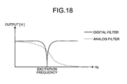
- Fig. 18 is a graph for explaining a filter characteristic of a digital filter of which the eliminating frequency is set to be the excitation frequency of the excitation pulse. Also, the characteristic of an analog filter equivalent to this digital filter is shown in the graph.
- a sampling is performed on the detection output while the sampling frequency is set to be 4.7 kilohertz (kHz), when the excitation frequency of the excitation pulse is 2 kilohertz.
- a filtering process is performed on a sampled output, based on the digital filter shown in Fig. 18 .
- the sampling is performed by using a higher sampling frequency, compared to the process performed according to the seventh embodiment.
- the digital filter lowers the gain precipitously near the target frequency.
- the digital filter is able to eliminate only the target frequency components with a high level of precision.
- digital filters have better temperature characteristic than analog filters. Thus, it is possible to perform the detection process with an even higher level of precision.
- the feedback loop is made up of the current detecting unit, the peak detecting unit, the adding unit, and the current regulating unit.
- the output of the peak detecting unit is regulated so as to be the target value by the control of the feedback loop.
- a zero-phase current flowing in the zero-phase-sequence current transformer is detected based on the output of the adding unit obtained when the output of the peak detecting unit is regulated so as to be equal to the target value.
- the control polarity reversal preventing unit provided between the output of the adding unit and the input of the current regulating unit operates so as to prevent the operating point of the peak detecting unit from reversing.
- the operating point of the peak detecting unit does not go out of the control range.
- the magnetization forcing unit controls the magnetized state of the detection core included in the zero-phase-sequence current transformer.
- the detection core included in the zero-phase-sequence current transformer maintains the predetermined magnetized state.
- the magnetization forcing unit repeatedly and continuously performs the magnetizing operation that lasts for a shorter period of time than the excitation cycle period of the excitation pulse output by the pulse generating unit, once in every regular or non-regular cycle period of the excitation pulse.
- the magnetization forcing unit repeatedly and continuously performs the magnetizing operation that lasts for a shorter period of time than the excitation cycle period of the excitation pulse output by the pulse generating unit, once in every regular or non-regular cycle period of the excitation pulse.
- the time constant of the high frequency passing unit that passes the high frequency component in the output of the adding unit is arranged to be equal to or longer than one second.
- the time constant changing unit that is operable to change the time constant of the high frequency passing unit temporarily makes the time constant smaller than the arranged value used during the operation. Thus, it is possible to shorten the period of time required to perform the zero adjustment.
- the digital processor that has the function of the high frequency passing unit outputs, as discrete values, sampled values out of the output of the adding unit that are obtained in synchronization with the excitation cycle period of the excitation pulse.
- the digital processor when outputting the sampled values out of the output of the adding unit as the discrete values, the digital processor that has the function of the high frequency passing unit obtains the sampled values by using a cycle period shorter than a half of the excitation cycle period of the excitation pulse and also eliminates the excitation frequency component of the excitation pulse contained in the discrete values by performing a digital signal processing.
- the digital processor that has the function of the high frequency passing unit obtains the sampled values by using a cycle period shorter than a half of the excitation cycle period of the excitation pulse and also eliminates the excitation frequency component of the excitation pulse contained in the discrete values by performing a digital signal processing.
- the zero-phase current detecting apparatus may be used as, for example, a ground-fault detecting circuit for a grid-connected inverter apparatus.
- the grid-connected inverter apparatus may be an inverter apparatus for a photovoltaic power generation system. It is more useful to apply the zero-phase current detecting apparatus according to the present invention to such a photovoltaic power generation system that has gotten a lot of attention as a clean energy source against the backdrop of recent increases in environmental problems on a world-wide scale.
- the zero-phase current detecting apparatus is useful for application to, for example, a ground-fault detecting circuit for a grid-connected inverter apparatus.
Landscapes
- Physics & Mathematics (AREA)
- General Physics & Mathematics (AREA)
- Measurement Of Current Or Voltage (AREA)
- Measuring Instrument Details And Bridges, And Automatic Balancing Devices (AREA)
Abstract
Description
- The present invention generally relates to a zero-phase current detecting apparatus. The present invention specifically relates to a zero-phase current detecting apparatus in which a zero-phase-sequence current transformer is used.
- A Zero-phase-sequence Current Transformer (ZCT) is a device that detects a zero-phase current flowing in an electric power line inserted through its own detection core. A ZCT is used, for example, in switchboards, electrical devices and the like, as a detector that detects a ground-fault current caused by a ground fault.
- Patent Documents 1 and 2 are examples of documents that disclose a current detecting apparatus and the like in which a ZCT is used. For example, Patent Document 1 discloses a direct-current ground-fault detecting apparatus that detects a ground fault of a direct current at a low cost with a high level of precision thereby ensuring a high level of safety. Patent Document 2 discloses a direct-current ground-fault current detecting circuit that accurately detects whether a direct-current ground-fault current has generated or accurately detects a direct-current value at a given moment without being influenced by the hysteresis characteristics of a ZCT.
- Patent Document 1: Japanese Patent Application Laid-open No.
2004-153991
Patent Document 2: Japanese Patent Application Laid-open No.2005-065382 - In the direct-current ground-fault detecting apparatus disclosed in Patent Document 1, a detection output from the ZCT is corrected based on a detection output from a temperature sensor that detects an atmospheric temperature near the ZCT. Accordingly, it is necessary to modify data used in the correction process depending on the type and the model of the ZCT being used and also to store, in advance, the data used in the correction process into a storage device such as a ROM. Consequently, this direct-current ground-fault detecting apparatus has a problem in that the mode of control for detecting a zero-phase current with a high level of precision becomes complicated, and the costs of designing and manufacturing the detecting apparatus become high.
- In he direct-current ground-fault current detecting circuit disclosed in Patent Document 2, the detecting circuit detects a current that flows on the secondary side of the ZCT (the side on which a detection coil wound around a detection core included in the ZCT is positioned; hereinafter, "the secondary side") by causing an offset current to flow on the primary side of the ZCT (the side on which the electric power line inserted through the detection core is positioned; hereinafter, "the primary side"). In this configuration, however, an output gain for the detection current detected in the detection coil on the secondary side varies, depending on the amount of the offset current that is caused to flow on the primary side. Thus, there is a problem in the direct-current ground-fault current detecting circuit disclosed in Patent Document 2 that the level of precision in the detection process for the zero-phase current degrades.
- This invention has been made in view of the above. It is an object of the present invention to provide a zero-phase current detecting apparatus in which a ZCT is used and that makes it possible to prevent degradation in the level of precision in the detection process without increasing the costs.
- To solve the above problems and achieve the objects, a zero-phase current detecting apparatus comprising a zero-phase-sequence current transformer that includes a detection coil and is operable to detect, via the detection coil, a zero-phase current flowing in an electric power line inserted through the zero-phase-sequence current transformer, includes a pulse generating unit that applies an excitation pulse signal to one end of the detection coil included in the zero-phase-sequence current transformer; a current detecting unit that is connected to other end of the detection coil and converts a current flowing via the detection coil into a voltage output; a peak detecting unit that detects a peak value of the output voltage output from the current detecting unit; an adding unit that outputs a difference value between a predetermined target value and the peak value; and a current regulating unit that regulates the current flowing in the detection coil based on an output of the adding unit, wherein a feedback loop is made up of the current detecting unit, the peak detecting unit, the adding unit, and the current regulating unit, and the zero-phase current is detected based on the output of the adding unit obtained when an output of the peak detecting unit is regulated so as to be the target value under the control of the feedback loop.
- In the zero-phase current detecting apparatus according to the present invention, a feedback loop is made up of the current detecting unit, the peak detecting unit, the adding unit, and the current regulating unit. A zero-phase current is detected based on an output of the adding unit obtained when an output of the peak detecting unit is regulated so as to be equal to the target value under the control of the feedback loop. Thus, an advantageous effect is achieved where it is possible to provide a zero-phase current detecting apparatus that makes it possible to prevent degradation in the level of precision in the detection process without increasing the costs.
-
- [
Fig. 1] Fig. 1 is a functional block diagram of a zero-phase current detecting apparatus according to a first embodiment of the present invention. - [
Fig. 2] Fig. 2 is a diagram of an exemplary circuit configuration of the zero-phase current detecting apparatus according to the first embodiment of the present invention to materialize the functional configuration shown inFig. 1 . - [
Fig. 3] Fig. 3 is a graph for explaining a relationship between a current that flows in a detection coil and a voltage output from a peak detecting circuit (when no zero-phase current flows). - [
Fig. 4] Fig. 4 is a graph for explaining a relationship between a current that flows in the detection coil and a voltage output from the peak detecting circuit (when a zero-phase current flows). - [
Fig. 5-1] Fig. 5-1 is a waveform diagram of the output of a current detector when no zero-phase current is flowing. - [
Fig. 5-2] Fig. 5-2 is a waveform diagram of the output of the current detector when a zero-phase current is flowing. - [
Fig. 6] Fig. 6 is a graph of the detection characteristic of the peak detecting circuit. - [
Fig. 7] Fig. 7 is a functional block diagram of a zero-phase current detecting apparatus according to a second embodiment of the present invention. - [
Fig. 8] Fig. 8 is a graph for explaining the function of a control polarity reversal preventing unit. - [
Fig. 9] Fig. 9 is a diagram of an exemplary circuit configuration of the zero-phase current detecting apparatus according to the second embodiment of the present invention to materialize the functional configuration shown inFig. 7 . - [
Fig. 10] Fig. 10 is a functional block diagram of a zero-phase current detecting apparatus according to a third embodiment of the present invention. - [
Fig. 11] Fig. 11 is a graph for explaining a function of a magnetization forcing unit. - [
Fig. 12] Fig. 12 is a diagram of an exemplary circuit configuration of the zero-phase current detecting apparatus according to the third embodiment of the present invention to materialize the functional configuration shown inFig. 10 . - [
Fig. 13] Fig. 13 is a graph of an exemplary embodiment for explaining an operation of a zero-phase current detecting apparatus according to a fourth embodiment of the present invention. - [
Fig. 14] Fig. 14 is a functional block diagram of a zero-phase current detecting apparatus according to a fifth embodiment of the present invention. - [
Fig. 15] Fig. 15 is a graph of an example of a temperature characteristic of a zero-phase-sequence current transformer ZCT. - [
Fig. 16] Fig. 16 is a functional block diagram of a zero-phase current detecting apparatus according to a sixth embodiment of the present invention. - [
Fig. 17] Fig. 17 is a graph of an exemplary embodiment for explaining an operation of a zero-phase current detecting apparatus according to a seventh embodiment of the present invention. - [
Fig. 18] Fig. 18 is a graph for explaining a filter characteristic of a digital filter of which the eliminating frequency is set to be an excitation frequency of an excitation pulse. -
- ZCT: zero-phase-sequence current transformer
- 10: electric power line
- 11: pulse generating unit
- 11a: pulse generator
- 12: current detecting unit
- 12a: current detector
- 12b: resistor
- 14: detection coil
- 15: peak detecting unit
- 15a: peak detecting circuit
- 18: adding unit
- 20: current regulating unit
- 21: proportional integral controller
- 25: target value
- 25a: target value output circuit
- 26: output terminal
- 30: control polarity reversal preventing unit
- 30a: control polarity reversal preventing circuit
- 32: magnetization forcing unit
- 32a: magnetization forcing circuit
- 32b: magnetization instruction generator
- 34: high frequency passing unit
- 36: time constant changing unit
- Exemplary embodiments of a zero-phase current detecting apparatus according to the present invention will be explained in detail with reference to the accompanying drawings. It should be noted that the present invention is not limited to these exemplary embodiments.
-
Fig. 1 is a functional block diagram of a zero-phase current detecting apparatus according to a first embodiment of the present invention. As shown in the drawing, the zero-phase current detecting apparatus according to the first embodiment is configured so as to include a zero-phase-sequence current transformer ZCT, apulse generating unit 11, a current detectingunit 12, apeak detecting unit 15, an addingunit 18, and acurrent regulating unit 20. - Next, a connection configuration of the zero-phase current detecting apparatus shown in
Fig. 1 will be explained. In the drawing, anelectric power line 10, which is a detection target for detecting whether a zero-phase current flows in it, is inserted through the zero-phase-sequence current transformer ZCT. The zero-phase-sequence current transformer ZCT includes adetection coil 14 that is wound around a detection core. Thepulse generating unit 11 is connected to one end of thedetection coil 14. The current detectingunit 12 is connected to the other end of thedetection coil 14. The output of the current detectingunit 12 serves as an input signal to thepeak detecting unit 15. The output of thepeak detecting unit 15 serves as an input signal to the addingunit 18. In addition to the output of thepeak detecting unit 15, apredetermined target value 25 is input to the addingunit 18. An output of the addingunit 18 is configured into an output terminal ("OUT PUT") 26 of the zero-phase current detecting apparatus according to this embodiment and also serves as an input signal to thecurrent regulating unit 20. The output of thecurrent regulating unit 20 is input to an input terminal of the current detectingunit 12 while acting on the current detectingunit 12 or thedetection coil 14. In the zero-phase current detecting apparatus according to this embodiment, as a result of the connections as described above, a feedback loop is made up of the current detectingunit 12, thepeak detecting unit 15, the addingunit 18, and thecurrent regulating unit 20, and the output of the addingunit 18 is output from theoutput terminal 26 as the output of the zero-phase current detecting apparatus. -
Fig. 2 is a diagram of an exemplary circuit configuration of the zero-phase current detecting apparatus according to the first embodiment of the present invention to materialize the functional configuration shown inFig. 1 . InFig. 2 , apulse generator 11a corresponds to thepulse generating unit 11 shown inFig. 1 . Similarly, acurrent detector 12a corresponds to the current detectingunit 12 and thecurrent regulating unit 20. Apeak detecting circuit 15a corresponds to thepeak detecting unit 15. A proportionalintegral controller 21 corresponds to the addingunit 18. A targetvalue output circuit 25a corresponds to thetarget value 25. It is possible to configure thecurrent detector 12a by using asingle resistor 12b, as shown in the drawing. It is possible to configure thepeak detecting circuit 15a by combining circuit elements such as an operational amplifier, a resistor, a capacitor, and a diode, as shown in the drawing. It is possible to configure the targetvalue output circuit 25a by using, for example, two resistors, as shown in the drawing. It is possible to configure the proportionalintegral controller 21 by combining circuit elements such as an operational amplifier, a resistor, and a capacitor, as shown in the drawing. In this manner, thecurrent detector 12a has the function of thecurrent regulating unit 20, in addition to the function of the current detectingunit 12. The details of the functions of thecurrent detector 12a will be explained later. - Next, the operation of the zero-phase current detecting apparatus according to the first embodiment will be explained, with reference to
Figs. 2 to 5 .Figs. 3 and 4 are graphs for explaining a relationship between a current that flows in thedetection coil 14 and an output voltage of thepeak detecting circuit 15a. InFig. 3 , a situation in which no zero-phase current is flowing in theelectric power line 10 is shown. Conversely, inFig. 4 , a situation in which a zero-phase current is flowing in theelectric power line 10 is shown.Fig. 5-1 is an output waveform of thecurrent detector 12a in a situation where no zero-phase current is flowing.Fig. 5-2 is an output waveform of thecurrent detector 12a in a situation where a zero-phase current is flowing. - In
Fig. 2 , an excitation pulse signal generated by thepulse generator 11a is input to one end of thedetection coil 14 included in the zero-phase-sequence current transformer ZCT through which theelectric power line 10 is inserted. As a result, the detection core (not shown) of the zero-phase-sequence current transformer ZCT is in an excited state. On the other hand, a zero-phase current flowing in theelectric power line 10 is detected by thedetection coil 14. Thecurrent detector 12a connected to the zero-phase-sequence current transformer ZCT converts the current flowing in thedetection coil 14 into a voltage. The voltage output from thecurrent detector 12a is input to thepeak detecting circuit 15a. Thepeak detecting circuit 15a detects a peak value of the output of thecurrent detector 12a and outputs the detected peak value. - The output of the
peak detecting circuit 15a is input to one of input terminals (i.e., the reversal input terminal) of the proportionalintegral controller 21. A target value γ set by the targetvalue output circuit 25a is input to the other of the input terminals (i.e., the non-reversal input terminal) of the proportionalintegral controller 21. The proportionalintegral controller 21 performs a proportional integral computation by using the difference between the target value γ and the output of thepeak detecting circuit 15a as an input signal. A proportional integral output is input to thecurrent detector 12a. - Next, the function of the
current detector 12a will be explained. As explained above, thecurrent detector 12a converts the current flowing in thedetection coil 14 into a voltage and outputs the voltage. In other words, thecurrent detector 12a has the function to detect the current flowing in the zero-phase-sequence current transformer ZCT. On the other hand, if we take a look at the connection of theresistor 12b that is included in thecurrent detector 12a, the output of the proportionalintegral controller 21 is connected to a terminal (a second end) of theresistor 12b that is different from a connection terminal (a first end) being connected to thedetection coil 14 included in the zero-phase-sequence current transformer ZCT. Because of this connection state, the output of the proportionalintegral controller 21 has an action to change the electric potential of the second end side of theresistor 12b that is used as a reference for the output of thecurrent detector 12a (i.e., the output to thepeak detecting circuit 15a). It is also acceptable to consider that this action is caused by a decrease in the voltage detected by thecurrent detector 12a because a current that corresponds to the output of the proportionalintegral controller 21 flows toward thepulse generator 11a via thedetection coil 14. In any case, thecurrent detector 12a also has the current regulating function to regulate the current flowing in thedetection coil 14, as shown in the functional diagram inFig. 1 . It is also acceptable to consider that this current regulating function is realized by collaboration between thecurrent detector 12a and the proportionalintegral controller 21 shown inFig. 2 . - Returning to the description of
Fig. 2 , a feedback loop is made up of thecurrent detector 12a, thepeak detecting circuit 15a, the targetvalue output circuit 25a, and the proportionalintegral controller 21. The difference between the output of thepeak detecting circuit 15a and the target value γ is subjected to feedback control by the feedback loop and regulated so that the output of thepeak detecting circuit 15a is always equal to the target value γ. In other words, when the output of thepeak detecting circuit 15a is expressed as η, the feedback control is exercised so that η=γ is always satisfied. - The state in this situation is shown in
Fig. 3 . InFig. 3 , the vertical axis shows the voltage output from thepeak detecting circuit 15a, while the horizontal axis shows the current flowing in thecurrent detector 12a (the detection coil 14). As explained above, while the output of thepeak detecting circuit 15a is controlled so as to be equal to the target value γ, the current flows taking a course as follows: the proportionalintegral controller 21 → thecurrent detector 12a → the zero-phase-sequence current transformer ZCT. This situation is the same as a state in which a zero-phase current I0 is equivalently flowing in theelectric power line 10. - From the situation shown in
Fig. 3 , if a zero-phase current ΔI flows in theelectric power line 10, the current flowing in thecurrent detector 12a via thedetection coil 14 has a tendency to change from I0 to I0+ΔI, and also, the output of thepeak detecting circuit 15a has a tendency to change from γ to γ', as shown with broken lines inFig. 4 . However, because the proportionalintegral controller 21 gives feedback of a control amount based on the difference between the target values γ and γ' to thecurrent detector 12a, the output of thepeak detecting circuit 15a is arranged so as to be always equal to the target value γ. As a result, the output of thepeak detecting circuit 15a is always constant regardless of the level of the zero-phase current flowing in theelectric power line 10. Also, the zero-phase current flowing in theelectric power line 10 is offset by a compensating current (having the same level as ΔI and being in a direction opposite to the direction of ΔI) that is caused to flow in the zero-phase-sequence current transformer ZCT by a change in the output of thecurrent detector 12a. Thus, the current that flows in the detection coil is constant and remains to be I0. Consequently, the flux in the detection core included in the zero-phase-sequence current transformer ZCT is maintained to be constant. - Next, the voltage output from the
current detector 12a, i.e., the voltage output from the present apparatus will be explained. First, when no zero-phase current is flowing in theelectric power line 10, the output waveform of thecurrent detector 12a changes according to the excitation pulse signal generated by thepulse generator 11a in the manner shown in the lower half ofFig. 5-1 . In this situation, thepeak detecting circuit 15a detects a peak value α of the output of the current detector. On the other hand, when a zero-phase current flows in theelectric power line 10, the current flowing in thedetection coil 14 maintains the constant value, as explained above; however, the electric potential at the other end of thecurrent detector 12a, i.e., the output of thecurrent detector 12a, changes as shown inFig. 5-2 . When the output of thepeak detecting circuit 15a at that time is expressed as β, the value of β is positively correlated with the level of the zero-phase current flowing in theelectric power line 10. Accordingly, it is possible to output the value of the zero-phase current flowing in theelectric power line 10, based on a difference between the value of α and the value of β. - Next, the current value (corresponding to I0 above) that is caused to flow in the
detection coil 14 in advance will be explained.Fig. 6 is a graph for explaining the detection characteristic of thepeak detecting circuit 15a. When a predetermined current is caused to flow in thedetection coil 14 in advance (corresponding to the situation shown inFig. 4 in which the current I0 is caused to flow in the detection coil 14), the detection characteristic of thepeak detecting circuit 15a have linearity in the area K1 in the drawing. Thus, it is possible to achieve a high level of precision in the detection process. On the other hand, when the level of the current caused to flow in thedetection coil 14 is small, the detection characteristic of thepeak detecting circuit 15a is non-linear in the area K2 in the drawing. Thus, it is difficult to keep the level of precision in the detection process high. Accordingly, it is desirable to set the target value γ being output by the targetvalue output circuit 25a to be at such a level that the output of thepeak detecting circuit 15a keeps its linearity. By setting the target value γ at such a level, it is possible to detect the zero-phase current with a high level of precision. - According to the first embodiment, the proportional
integral controller 21 shown inFig. 2 is used as the addingunit 18 shown inFig. 1 . However, when the gain of the proportionalintegral controller 21 is not so large, it is acceptable to use a proportional controller that includes no capacitor in the feedback portion. -
Fig. 7 is a functional block diagram of a zero-phase current detecting apparatus according to a second embodiment of the present invention. As shown in the drawing, in the zero-phase current detecting apparatus according to the second embodiment, the configuration of the zero-phase current detecting apparatus shown inFig. 1 is used as the base. In addition, the zero-phase current detecting apparatus further includes a control polarityreversal preventing unit 30 provided between the addingunit 18 and thecurrent regulating unit 20. The control polarityreversal preventing unit 30 has a function (called an operation range limiting function) to prevent the operating point of thepeak detecting unit 15 from going out of a control range so that the detection core included in the zero-phase-sequence current transformer ZCT does not become saturated. Other configurations of the zero-phase current detecting apparatus according to the second embodiment are the same as or similar to the configuration of the zero-phase current detecting apparatus according to the first embodiment shown inFig. 1 . The constituent elements in the same or similar configurations will be referred to by using the same reference characters, and the explanation thereof will be omitted. -
Fig. 8 is a graph for explaining the function of the control polarityreversal preventing unit 30. As explained above, when the output of thepeak detecting unit 15 is larger than the target value Y, the output of thepeak detecting unit 15 changes so as to become equal to the target value γ. This situation is equivalent to a situation obtained when a negative zero-phase current is caused to flow in the zero-phase-sequence current transformer ZCT. Also, when the output of thepeak detecting unit 15 is smaller than the target value γ, the output of thepeak detecting unit 15 changes so as to equal to the target value γ. This situation is equivalent to a situation obtained when a positive zero-phase current is caused to flow in the zero-phase-sequence current transformer ZCT. - On the other hand, if a large zero-phase current flows in this situation, the current that flows in the current detecting unit 12 (i.e., the detection coil 14) is reversed, as shown in
Fig. 8 . As a result, the operating point at which the target value γ is output moves from the point A (the current value I0) to the point A' (the current value I'). In this situation, when the output of thepeak detecting unit 15 is larger than the target value γ, the output of thepeak detecting unit 15 changes so as to become equal to the target value γ. This operation is equivalent to an action of causing a large negative zero-phase current corresponding to ΔI' shown inFig. 8 to flow in the zero-phase-sequence current transformer ZCT. Thus, the operation is out of a normal control range, and the detection core included in the zero-phase-sequence current transformer ZCT becomes saturated. - Generally speaking, a situation rarely occurs in which the operation is out of the control range because of a large zero-phase current. However, if a large zero-phase current should flow by any chance, there is a possibility that the operation goes out of the control range assumed by the zero-phase current detecting apparatus according to the present invention.
- To cope with this problem, according to the second embodiment, the control polarity
reversal preventing unit 30 is provided between the addingunit 18 and thecurrent regulating unit 20. -
Fig. 9 is a diagram of an exemplary circuit configuration of the zero-phase current detecting apparatus according to the second embodiment of the present invention to materialize the functional configuration shown inFig. 7 . In the configuration shown inFig. 9 , a control polarityreversal preventing circuit 30a is provided as a constituent element that corresponds to the control polarityreversal preventing unit 30 shown inFig. 7 . It is possible to configure the control polarityreversal preventing circuit 30a by combining circuit elements such as an operational amplifier and a diode as shown in the drawings. Other constituent elements are the same as the ones in the circuit configuration shown inFig. 2 . Those constituent elements will be referred to by using the same reference characters, and the explanation thereof will be omitted. - In
Fig. 9 , the output of the proportionalintegral controller 21 serves an input signal to the control polarityreversal preventing circuit 30a and is input to a non-reversal input terminal of the operational amplifier. The non-reversal input terminal of the operational amplifier is connected to a ground via the diode. Thus, even if a current that exceeds the control range limit value flows on the primary side (i.e., the electric power line 10) of the zero-phase-sequence current transformer ZCT, the output of the proportionalintegral controller 21 is input to thecurrent detector 12a after being clipped based on the control range limit value determined by the circuit elements of the control polarityreversal preventing circuit 30a. Consequently, even if a large zero-phase current should flow, the detection core included in the zero-phase-sequence current transformer ZCT is prevented from becoming saturated. It is therefore possible to detect the zero-phase current with a high level of precision. -
Fig. 10 is a functional block diagram of a zero-phase current detecting apparatus according to a third embodiment of the present invention. As shown in the drawing, in the zero-phase current detecting apparatus according to the third embodiment, the configuration of the zero-phase current detecting apparatus shown inFig. 1 is used as the base. In addition, the zero-phase current detecting apparatus further includes amagnetization forcing unit 32 that acts on the current detectingunit 12 or thedetection coil 14. Themagnetization forcing unit 32 has a function to exercise control so that the detection core included in the zero-phase-sequence current transformer ZCT is in a predetermined magnetized state. Other configurations of the zero-phase current detecting apparatus according to the third embodiment are the same as or similar to the configuration of the zero-phase current detecting apparatus according to the first embodiment shown inFig. 1 . The constituent elements in the same or similar configurations will be referred to by using the same reference characters, and the explanation thereof will be omitted. -
Fig. 11 is a graph for explaining the function of themagnetization forcing unit 32. As explained above, in the zero-phase current detecting apparatus according to the first or the second embodiment, thecurrent regulating unit 20 operates so as to exercise control in such a manner that the current flowing in the detection coil is constant. However, when a zero-phase current flows in theelectric power line 10, the magnetic flux within the detection core included in the zero-phase-sequence current transformer ZCT changes. After the magnetic flux has changed repeatedly, the magnetized state of the detection core also changes. If the magnetized state of the detection core changes, the output characteristic of thepeak detecting unit 15 changes, for example, from the one shown with a broken line to the one shown with a solid line, as shown inFig. 11 . Thus, there is a possibility that the level of precision in the detection process is lowered. - To cope with this problem, according to the third embodiment, the
magnetization forcing unit 32 that acts on the current detectingunit 12 or thedetection coil 14 is provided, as explained above. -
Fig. 12 is a diagram of an exemplary circuit configuration of the zero-phase current detecting apparatus according to the third embodiment of the present invention to materialize the functional configuration shown inFig. 10 . InFig. 12 , the control polarityreversal preventing circuit 30a shown inFig. 9 is also provided at the same time. However, needless to say, it is acceptable to use a configuration in which the control polarityreversal preventing circuit 30a is not included. - In
Fig. 12 , amagnetization forcing circuit 32a and amagnetization instruction generator 32b that controls themagnetization forcing circuit 32a are provided as constituent elements that correspond to themagnetization forcing unit 32 shown inFig. 10 . It is possible to configure themagnetization forcing circuit 32a by combining circuit elements such as a transistor and a resistor as shown in the drawing. It is possible to configure themagnetization instruction generator 32b by using a digital processor such as a microcomputer. Other constituent elements are the same as the ones in the circuit configuration shown inFig. 9 . Those constituent elements will be referred to by using the same reference characters, and the explanation thereof will be omitted. - As shown in
Fig. 12 , themagnetization forcing circuit 32a brings the current flowing in thedetection coil 14 into themagnetization forcing circuit 32a (when I1>0) or sends a current into the detection coil 14 (when I1<0), based on the control of themagnetization instruction generator 32b. In other words, themagnetization instruction generator 32b exercises control so that the magnetized state of the detection core included in the zero-phase-sequence current transformer ZCT maintains a predetermined state (for example, the state obtained at a reference point in time) by regulating the magnetizing current I1 that is caused to flow in thedetection coil 14 via themagnetization forcing circuit 32a. Accordingly, in the zero-phase current detecting apparatus according to the third embodiment, because the magnetized state of the detection core included in the zero-phase-sequence current transformer ZCT is stabilized, changes in the output characteristic of thepeak detecting unit 15 are inhibited. Thus, it is possible to detect the current with a high level of precision, without receiving any influence from external magnetizing factors. - It is acceptable to configure the
magnetization instruction generator 32b by using a controller other than a microcomputer. It should be noted, however, that by configuring themagnetization instruction generator 32b by using a microcomputer, it is possible to exercise control in a finely-tuned manner with regard to magnetization instructions (e.g. magnetization periods and magnetization timing) and the like. Thus, it is possible to detect the current with an even higher level of precision. - In the configuration described above, the magnetizing current I1 that is caused to flow in the
detection coil 14 is regulated via themagnetization forcing circuit 32a; however, another arrangement is also acceptable in which a secondary coil (i.e., a magnetization control coil) that is different from thedetection coil 14 is provided so that the magnetizing current I1 is caused to flow in the magnetization control coil. - Yet another arrangement is also acceptable in which a control line that is different from the
electric power line 10 is inserted through the detection core included in the zero-phase-sequence current transformer ZCT so that the magnetizing current is caused to flow in the control line. temporarily - When a method that employs the detection coil or a secondary coil such as the magnetization control coil is used, the current level proportional to the ratio of the number of turns of the coil is considered to be equivalent to the level of a current flowing through the detection core included in the zero-phase-sequence current transformer ZCT. Thus, it is possible to make the current used in the magnetization control smaller.
- Also, when a method that employs such a secondary coil is used, if an exclusive-use coil such as the magnetization control coil is employed, it is possible to exercise control simultaneously and independently so that the output voltage of the peak detecting circuit is stabilized, and also the magnetized state of the detection core included in the zero-phase-sequence current transformer ZCT is stabilized. Thus, it is possible to maintain the ease with which the control is exercised. Consequently, it is possible to exercise control with an even higher level of precision.
- On the other hand, when a method that employs such a secondary coil is used, if the detection coil is employed, it is possible to use a general-purpose zero-phase-sequence current transformer ZCT. Thus, it is possible to configure the zero-phase current detecting apparatus at a low cost.
- In addition, when the method in which a current is caused to flow on the primary side of the zero-phase-sequence current transformer ZCT is used, it is also possible to use a general-purpose zero-phase-sequence current transformer ZCT. Thus, it is possible to configure the zero-phase current detecting apparatus at a low cost.
- Next, a zero-phase current detecting apparatus according to a fourth embodiment of the present invention will be explained. The zero-phase current detecting apparatus according to the fourth embodiment is characterized in that it provides a control method to maintain detection performances with an even higher level of precision by appropriately controlling the magnetizing current applied to the detection core included in the zero-phase-sequence current transformer ZCT so as to prevent the detection core included in the zero-phase-sequence current transformer ZCT from becoming saturated. The zero-phase current detecting apparatus according to the fourth embodiment may have a configuration similar to that of the zero-phase current detecting apparatus according to the third embodiment.
- Based on the configuration of the zero-phase current detecting apparatus according to the third embodiment, let us discuss a situation in which a magnetizing current is forcibly caused to flow in a predetermined coil so that the magnetized state of the detection core included in the zero-phase-sequence current transformer ZCT can be controlled. In this situation, the detection core included in the zero-phase-sequence current transformer ZCT may become saturated, depending on the current amount of the magnetizing current that is forcibly caused to flow. In such a situation, it is difficult to detect a zero-phase current. Accordingly, to prevent the detection core included in the zero-phase-sequence current transformer ZCT from becoming saturated, it is necessary to control the current amount of the magnetizing current so as to be at an appropriate level.
- For example, it is desirable to continuously perform an operation to cause a magnetizing pulse current to flow (hereinafter, "magnetizing operation") for a short period of time. By exercising control this way, it is possible to prevent the detection core included in the zero-phase-sequence current transformer ZCT from becoming saturated and to perform the detection process with an even higher level of precision.
- Also, when the magnetizing operation is continuously performed for a short period of time as described above, it is desirable to cause the magnetizing pulse current to flow in synchronization with an excitation pulse. When the magnetizing pulse current is not in synchronization with an excitation pulse, the state of the magnetic flux of the detection core included in the zero-phase-sequence current transformer ZCT during a cycle period in which the magnetizing operation is performed is different from the state of the magnetic flux during a cycle period in which no magnetizing operation is performed. Thus, the output of the peak detecting circuit is not stable. However, if the magnetizing operation is performed in synchronization with the excitation pulse, it is possible to stabilize the operation of the peak detecting circuit.
- Accordingly, by performing the magnetizing operation one or more times in every excitation cycle period, it is possible to exercise control so that the magnetized state of the detection core included in the zero-phase-sequence current transformer ZCT maintains the predetermined state. Thus, it is possible to maintain a stable magnetized state.
- It is preferable to have an arrangement so that the length of the period in which the magnetizing operation is performed for a short period of time is equal to or shorter than 20% of the excitation cycle period (more preferably, equal to or shorter than 5% of the excitation cycle period) and also so that one output is made in every excitation cycle period. With this arrangement, it is possible to prevent the detection core included in the zero-phase-sequence current transformer ZCT from becoming saturated and to perform the detection process with an even higher level of precision.
- For example, as shown in
Fig. 13 , by having an arrangement so that the magnetizing pulse is in synchronization with the excitation pulse and so that the cycle period of the magnetizing pulse is 5% of the excitation cycle period, it is possible to maintain a stable magnetized state and to perform the detection process with a high level of precision. -
Fig. 14 is a functional block diagram of a zero-phase current detecting apparatus according to a fifth embodiment of the present invention. As shown in the drawing, in the zero-phase current detecting apparatus according to the fifth embodiment, the configuration of the zero-phase current detecting apparatus shown inFig. 1 is used as the base. In addition, the zero-phase current detecting apparatus further includes a highfrequency passing unit 34 provided between the addingunit 18 and theoutput terminal 26. The highfrequency passing unit 34 has a function to filter an output fluctuation caused by a temperature characteristic of the zero-phase-sequence current transformer ZCT. Other configurations of the zero-phase current detecting apparatus according to the fifth embodiment are the same as or similar to the configuration of the zero-phase current detecting apparatus according to the first embodiment shown inFig. 1 . The constituent elements in the same or similar configurations will be referred to by using the same reference characters, and the explanation thereof will be omitted. -
Fig. 15 is a graph of an example of the temperature characteristic of the zero-phase-sequence current transformer ZCT. The vertical axis shows the detection output of the zero-phase-sequence current transformer ZCT, while the horizontal axis shows the zero-phase current. As shown in the drawing, the output of zero-phase-sequence current transformer ZCT largely fluctuates, depending on changes in the ambient temperature thereof. Thus, the level of precision in the process to detect the zero-phase current can be lowered. To cope with this problem, according to the fifth embodiment, the highfrequency passing unit 34 is provided between the addingunit 18 and theoutput terminal 26, as shown inFig. 14 . - On the other hand, the changes in the detection output of the zero-phase-sequence current transformer ZCT are determined by a time constant for the changes in the ambient temperature. The time constant is sufficiently larger than a time required to perform the zero-phase current detection. Thus, it is possible to perform a filtering process by using the high
frequency passing unit 34. By performing the filtering process, it is possible to limit the influence from the changes in the ambient temperature and to perform the zero-phase current detection process with a high level of precision. - When the time constant of the high
frequency passing unit 34 is arranged to be a short period of time, there is a higher possibility that a change in the output caused by detection of a zero-phase current and a change in the output caused by a change in the ambient temperature are erroneously detected. To cope with this problem, it is desirable to have an arrangement in which the time constant of the highfrequency passing unit 34 is, for example, equal to or longer than 10 seconds. By having the arrangement in which the time constant of the highfrequency passing unit 34 is equal to or longer than 10 seconds, it is possible to detect a component that has a frequency equal to or higher than 0.016 hertz (Hz), out of the detection output of the peak detecting unit. Thus, it is possible to inhibit influence from the changes in the ambient temperature and to perform the detection process with a high level of precision. - Also, depending on the degree with which the ambient temperature changes (the difference when the environment is good and when the environment is bad), another arrangement is acceptable in which the time constant of the high
frequency passing unit 34 is, for example, equal to or longer than 1 minute, or equal to or longer than 20 minutes. By having the arrangement in which the value of the time constant is changed, as necessary, depending on the usage environment, it is possible to reduce the amount of undetected components related to the zero-phase current. It is also possible to lower the possibility of erroneous detection caused by the changes in the ambient temperature. - Like the
magnetization forcing unit 32 according to the third embodiment, it is possible to configure the highfrequency passing unit 34 by using a microcomputer. When the highfrequency passing unit 34 is configured by using a microcomputer, there is no need to provide a filtering circuit. Thus, it is possible to perform the detection process with a high level of precision at a low cost. - In the description of the fifth embodiment, the example has been explained in which the configuration including the high
frequency passing unit 34 provided between the addingunit 18 and theoutput terminal 26 is applied to the zero-phase current detecting apparatus according to the first embodiment shown inFig. 1 . However, it is also acceptable to apply the configuration including the highfrequency passing unit 34 to the configuration according to the second embodiment in which the control polarityreversal preventing unit 30 is included or to the configuration according to the third embodiment in which themagnetization forcing unit 32 is included. In these situations, it is possible to achieve the advantageous effect of those embodiments, in addition to the advantageous effect of the fifth embodiment. -
Fig. 16 is a functional block diagram of a zero-phase current detecting apparatus according to a sixth embodiment of the present invention. As shown in the drawing, the zero-phase current detecting apparatus according to the sixth embodiment further includes a timeconstant changing unit 36 that is operable to change the time constant of the highfrequency passing unit 34, in addition to the configuration of the zero-phase current detecting apparatus shown inFig. 14 . Other configurations of the zero-phase current detecting apparatus according to the sixth embodiment are the same as or similar to the configuration of the zero-phase current detecting apparatus according to the sixth embodiment shown inFig. 14 . The constituent elements in the same or similar configurations will be referred to by using the same reference characters, and the explanation thereof will be omitted. - In the description of the fifth embodiment, the example has been explained in which the time constant of the high
frequency passing unit 34 is arranged to be, for example, equal to or longer than 10 seconds, so that it is possible to detect the component that has a frequency equal to or higher than 0.016 hertz, out of the detection output of the peak detecting unit. - On the other hand, to detect a zero-phase current, it is necessary to adjust a zero point (i.e., to perform an offset calibration) so that an output obtained when no zero-phase current is flowing is zero.
- When the filtered output of the high
frequency passing unit 34 is expressed as V(t), it is possible to express V(t) by using Equation (1):
where t=detection period, T=time constant, and V0=regulated target voltage - As understood from Equation (1), when the time constant is large, it takes a longer period of time to adjust the zero point.
- To cope with this problem, in the zero-phase current detecting apparatus according to the sixth embodiment, when the offset calibration process is performed, the time
constant changing unit 36 temporarily changes the time constant of the high frequency passing unit 34 (i.e., makes it smaller). By performing the time constant changing control this way, it is possible to shorten the period of time required to adjust the zero point. - If the time constant used when the zero point adjustment is performed is changed to 1 second, and the calibration period is 4 seconds, it is possible to obtain the following Equation from Equation (1) :

It means that it is possible to make a fluctuation in the zero point adjustment equal to or lower than 2%, with a calibration period of 4 seconds. - In the description of the sixth embodiment, the example has been explained in which the configuration including the time
constant changing unit 36 is applied to the zero-phase current detecting apparatus according to the fifth embodiment shown inFig. 14 . However, it is also acceptable to apply the configuration including the timeconstant changing unit 36 to the configuration according to any one of the first to the fourth embodiments including the highfrequency passing unit 34. In these situations, it is possible to achieve the advantageous effect of those embodiments, in addition to the advantageous effect of the sixth embodiment. - Next, a zero-phase current detecting apparatus according to a seventh embodiment of the present invention will be explained. The zero-phase current detecting apparatus according to the seventh embodiment is characterized in that it provides a control method to maintain detection performances with an even higher level of precision by preventing a ripple component related to an excitation frequency of the excitation pulse from being present in a detection output. The zero-phase current detecting apparatus according to the seventh embodiment may have a configuration similar to that of the zero-phase current detecting apparatus according to any one of the first to the sixth embodiment.
- For example, in the zero-phase current detecting apparatus according to the first embodiment, an arrangement is made so that discrete values are each obtained from a predetermined phase every time (i.e., the phase is the same every time) in synchronization with the excitation cycle period of the excitation pulse, as shown in
Fig. 17 . By exercising control this way, it is possible to effectively suppress the ripple component contained in the detection output. Thus, it is possible to maintain a high level of precision in the detection process. - Next, a zero-phase current detecting apparatus according to an eighth embodiment of the present invention will be explained. The zero-phase current detecting apparatus according to the eighth embodiment is characterized in that, after a detection output is obtained as discrete values by using a sampling interval having a cycle period shorter than a half of the excitation cycle period (i.e., the frequency is two or more times higher), an excitation frequency component is eliminated by performing a digital signal processing. The zero-phase current detecting apparatus according to the eighth embodiment may have a configuration similar to that of the zero-phase current detecting apparatus according to any one of the first to the seventh embodiments.
-
Fig. 18 is a graph for explaining a filter characteristic of a digital filter of which the eliminating frequency is set to be the excitation frequency of the excitation pulse. Also, the characteristic of an analog filter equivalent to this digital filter is shown in the graph. - For example, by using the zero-phase current detecting apparatus according to the first embodiment, a sampling is performed on the detection output while the sampling frequency is set to be 4.7 kilohertz (kHz), when the excitation frequency of the excitation pulse is 2 kilohertz. After that, a filtering process is performed on a sampled output, based on the digital filter shown in
Fig. 18 . More specifically, according to the eighth embodiment, the sampling is performed by using a higher sampling frequency, compared to the process performed according to the seventh embodiment. As a result, after many of signal components (i.e., the target components) contained in the detection output are extracted, it is possible to eliminate the ripple component (i.e., the excitation frequency component) contained in the extracted components by using the precipitous digital filter. Accordingly, when the zero-phase current detecting apparatus according to the eighth embodiment is used, it is possible to effectively suppress the ripple component contained in the detection output. Thus, it is possible to maintain an even higher level of precision in the detection process. - As shown in
Fig. 18 , compared to the analog filter, the digital filter lowers the gain precipitously near the target frequency. Thus, the digital filter is able to eliminate only the target frequency components with a high level of precision. Also, digital filters have better temperature characteristic than analog filters. Thus, it is possible to perform the detection process with an even higher level of precision. - As explained above, in the zero-phase current detecting apparatus according to the first embodiment, the feedback loop is made up of the current detecting unit, the peak detecting unit, the adding unit, and the current regulating unit. The output of the peak detecting unit is regulated so as to be the target value by the control of the feedback loop. A zero-phase current flowing in the zero-phase-sequence current transformer is detected based on the output of the adding unit obtained when the output of the peak detecting unit is regulated so as to be equal to the target value. Thus, it is possible to have the detection characteristic of the peak detecting unit positioned in a linear area having linearity. Thus, it is possible to achieve a high level of precision in the detection process. In addition, there is no need to choose a special detector to maintain the level of precision in the detection process. Thus, it is possible to configure a zero-phase current detecting apparatus having a high level of precision in the detection process at a low cost.
- Also, in the zero-phase current detecting apparatus according to the second embodiment, the control polarity reversal preventing unit provided between the output of the adding unit and the input of the current regulating unit operates so as to prevent the operating point of the peak detecting unit from reversing. Thus, even if a large current flows, the operating point of the peak detecting unit does not go out of the control range. Thus, it is possible to maintain a high level of precision in the detection process.
- Further, in the zero-phase current detecting apparatus according to the third embodiment, the magnetization forcing unit controls the magnetized state of the detection core included in the zero-phase-sequence current transformer. Thus, the detection core included in the zero-phase-sequence current transformer maintains the predetermined magnetized state. Thus, it is possible to detect the current with a high level of precision, without receiving any influence from external magnetizing factors.
- Furthermore, in the zero-phase current detecting apparatus according to the fourth embodiment, the magnetization forcing unit repeatedly and continuously performs the magnetizing operation that lasts for a shorter period of time than the excitation cycle period of the excitation pulse output by the pulse generating unit, once in every regular or non-regular cycle period of the excitation pulse. Thus, it is possible to maintain a stable magnetized state. Accordingly, it is possible to perform the detection process with a high level of precision.
- Also, in the zero-phase current detecting apparatus according to the fifth embodiment, the time constant of the high frequency passing unit that passes the high frequency component in the output of the adding unit is arranged to be equal to or longer than one second. Thus, it is possible to detect a component that has a frequency equal to or higher than 0.016 hertz, out of the detection output of the peak detecting unit. Consequently, it is possible to inhibit the influence from the changes in the ambient temperature and to perform the detection process with a high level of precision.
- Further, in the zero-phase current detecting apparatus according to the sixth embodiment, when a zero point adjustment is performed upon an activation of the zero-phase current detecting apparatus, the time constant changing unit that is operable to change the time constant of the high frequency passing unit temporarily makes the time constant smaller than the arranged value used during the operation. Thus, it is possible to shorten the period of time required to perform the zero adjustment.
- Furthermore, in the zero-phase current detecting apparatus according to the seventh embodiment, the digital processor that has the function of the high frequency passing unit outputs, as discrete values, sampled values out of the output of the adding unit that are obtained in synchronization with the excitation cycle period of the excitation pulse. Thus, it is possible to effectively suppress the ripple component contained in the detection output. Consequently, it is possible to maintain a high level of precision in the detection process.
- Also, in the zero-phase current detecting apparatus according to the eighth embodiment, when outputting the sampled values out of the output of the adding unit as the discrete values, the digital processor that has the function of the high frequency passing unit obtains the sampled values by using a cycle period shorter than a half of the excitation cycle period of the excitation pulse and also eliminates the excitation frequency component of the excitation pulse contained in the discrete values by performing a digital signal processing. Thus, it is possible to effectively suppress the ripple component contained in the detection output. Consequently, it is possible to maintain an even higher level of precision in the detection process.
- It is possible to use the zero-phase current detecting apparatus according to any one of the first to the eighth embodiments as, for example, a ground-fault detecting circuit for a grid-connected inverter apparatus. In particular, the grid-connected inverter apparatus may be an inverter apparatus for a photovoltaic power generation system. It is more useful to apply the zero-phase current detecting apparatus according to the present invention to such a photovoltaic power generation system that has gotten a lot of attention as a clean energy source against the backdrop of recent increases in environmental problems on a world-wide scale.
- As explained above, the zero-phase current detecting apparatus according to the present invention is useful for application to, for example, a ground-fault detecting circuit for a grid-connected inverter apparatus.
Claims (20)
- A zero-phase current detecting apparatus comprising a zero-phase-sequence current transformer that includes a detection coil and is operable to detect, via the detection coil, a zero-phase current flowing in an electric power line inserted through the zero-phase-sequence current transformer, the zero-phase current detecting apparatus comprising:a pulse generating unit that applies an excitation pulse signal to one end of the detection coil included in the zero-phase-sequence current transformer;a current detecting unit that is connected to other end of the detection coil and converts a current flowing via the detection coil into a voltage output;a peak detecting unit that detects a peak value of the output voltage output from the current detecting unit;an adding unit that outputs a difference value between a predetermined target value and the peak value; anda current regulating unit that regulates the current flowing in the detection coil based on an output of the adding unit, whereina feedback loop is made up of the current detecting unit, the peak detecting unit, the adding unit, and the current regulating unit, andthe zero-phase current is detected based on the output of the adding unit obtained when an output of the peak detecting unit is regulated so as to be the target value under the control of the feedback loop.
- The zero-phase current detecting apparatus according to claim 1, further comprising a target-value setting circuit that is operable to change the predetermined target value, wherein
the predetermined target value is set so that an operating point of the peak detecting unit is positioned in a linear area within an output characteristic of the peak detecting unit. - The zero-phase current detecting apparatus according to claim 2, further comprising an operation-range limiting unit that prevents an operating point of the peak detecting unit from going out of a control range, the operation-range limiting unit being provided between an output of the adding unit and an input of the current regulating unit.
- The zero-phase current detecting apparatus according to claim 1, further comprising a magnetization forcing unit that controls a magnetized state of a detection core of the zero-phase-sequence current transformer.
- The zero-phase current detecting apparatus according to claim 4, wherein a magnetization control exercised by the magnetization forcing unit is achieved by causing a current to flow through a secondary coil of the zero-phase-sequence current transformer.
- The zero-phase current detecting apparatus according to claim 5, wherein the secondary coil of the zero-phase-sequence current transformer is the detection coil.
- The zero-phase current detecting apparatus according to claim 5, wherein the secondary coil of the zero-phase-sequence current transformer is a magnetization control coil that is different from the detection coil and is wound around the detection core.
- The zero-phase current detecting apparatus according to claim 4, wherein a magnetization control exercised by the magnetization forcing unit is achieved by causing a current to flow through a primary side of the zero-phase-sequence current transformer.
- The zero-phase current detecting apparatus according to claim 4, wherein the magnetization forcing unit repeatedly and continuously performs a magnetizing operation that lasts for a shorter period of time than an excitation cycle of the excitation pulse output by the pulse generating unit, once in every regular or non-regular cycle period of the excitation pulse.
- The zero-phase current detecting apparatus according to claim 4, wherein when exercising a magnetization control, the magnetization forcing unit suppresses a magnetizing current that is caused to flow so that the flowing of the magnetizing current is equal to or shorter than 20% of an excitation cycle of the excitation pulse.
- The zero-phase current detecting apparatus according to claim 4, wherein the magnetization forcing unit performs a magnetizing operation one or more times in every excitation cycle period.
- The zero-phase current detecting apparatus according to claim 4, wherein the magnetization forcing unit is configured with a digital processor.
- The zero-phase current detecting apparatus according to claim 1, further comprising a high-frequency passing unit that passes a high frequency component in the output of the adding unit, wherein
a time constant of the high-frequency passing unit is arranged to be equal to or longer than one second. - The zero-phase current detecting apparatus according to claim 13, further comprising a time-constant changing unit that is operable to change the time constant of the high-frequency passing unit, wherein
when a zero point adjustment is performed upon an activation of the zero-phase current detecting apparatus, the time-constant changing unit temporarily makes the time constant smaller than the arranged value. - The zero-phase current detecting apparatus according to claim 14, wherein the high-frequency passing unit and the time-constant changing unit are configured with a digital processor.
- The zero-phase current detecting apparatus according to claim 15, wherein the digital processor outputs, as discrete values, sampled values out of the output of the adding unit that are obtained in synchronization with an excitation cycle period of the excitation pulse.
- The zero-phase current detecting apparatus according to claim 16, wherein the digital processor obtains the discrete values from a predetermined phase position within the excitation cycle period.
- The zero-phase current detecting apparatus according to claim 16, wherein the digital processor obtains the discrete values by using a cycle period shorter than a half of the excitation cycle period and eliminates an excitation frequency component of the excitation pulse contained in the discrete values by performing a digital signal processing.
- The zero-phase current detecting apparatus according to any one of claims 1 to 18, wherein the zero-phase current detecting apparatus is used as a ground-fault detecting circuit for a grid-connected inverter apparatus.
- The zero-phase current detecting apparatus according to claim 19, wherein the grid-connected inverter apparatus is an inverter apparatus for a photovoltaic power generation system.
Applications Claiming Priority (1)
| Application Number | Priority Date | Filing Date | Title |
|---|---|---|---|
| PCT/JP2006/317195 WO2008026276A1 (en) | 2006-08-31 | 2006-08-31 | Zero-phase current detecting apparatus |
Publications (2)
| Publication Number | Publication Date |
|---|---|
| EP1933156A1 true EP1933156A1 (en) | 2008-06-18 |
| EP1933156A4 EP1933156A4 (en) | 2011-03-02 |
Family
ID=39135568
Family Applications (1)
| Application Number | Title | Priority Date | Filing Date |
|---|---|---|---|
| EP06797155A Withdrawn EP1933156A4 (en) | 2006-08-31 | 2006-08-31 | DEVICE FOR DETECTING ZERO CURRENT |
Country Status (4)
| Country | Link |
|---|---|
| US (1) | US7696743B2 (en) |
| EP (1) | EP1933156A4 (en) |
| JP (1) | JP4885121B2 (en) |
| WO (1) | WO2008026276A1 (en) |
Families Citing this family (17)
| Publication number | Priority date | Publication date | Assignee | Title |
|---|---|---|---|---|
| JP4306781B2 (en) * | 2007-10-30 | 2009-08-05 | ダイキン工業株式会社 | Earth leakage detection circuit |
| US8488342B2 (en) | 2008-10-21 | 2013-07-16 | On-Bright Electronics (Shanghai) Co., Ltd. | Systems and methods for constant voltage mode and constant current mode in flyback power converters with primary-side sensing and regulation |
| CN102812369B (en) * | 2010-04-14 | 2014-12-10 | 三菱电机株式会社 | Insulation deterioration diagnosis device |
| CN102769383B (en) | 2011-05-05 | 2015-02-04 | 广州昂宝电子有限公司 | System and method for constant-current control via primary side sensing and regulating |
| US9250274B2 (en) * | 2011-08-25 | 2016-02-02 | Asco Power Technologies, L.P. | Power analysis module for monitoring an electrical power source |
| CN105246194B (en) | 2011-11-15 | 2018-07-03 | 昂宝电子(上海)有限公司 | For the LED illumination System and method of the current constant control in various operation modes |
| JP5825135B2 (en) * | 2012-02-15 | 2015-12-02 | オムロン株式会社 | Detection apparatus and method, and program |
| CN103368400B (en) | 2012-03-31 | 2015-02-18 | 昂宝电子(上海)有限公司 | System and method for constant voltage control and constant current control |
| CN102790531B (en) | 2012-07-24 | 2015-05-27 | 昂宝电子(上海)有限公司 | System for electric current control of power supply alternation system |
| CN103076486A (en) * | 2013-01-18 | 2013-05-01 | 浪潮电子信息产业股份有限公司 | Wiring method capable of improving power supply feedback precision |
| US20150247886A1 (en) | 2014-02-28 | 2015-09-03 | International Business Machines Corporation | Transformer Phase Permutation Causing More Uniform Transformer Phase Aging and general switching network suitable for same |
| CN103956900B (en) | 2014-04-23 | 2017-08-11 | 广州昂宝电子有限公司 | Systems and methods for output current regulation in power conversion systems |
| KR101803132B1 (en) * | 2014-04-28 | 2017-11-29 | 엘에스산전 주식회사 | Apparatus for Monitoring Residual Current of Transformer-less PV Inverter |
| JP2017150817A (en) * | 2014-07-04 | 2017-08-31 | パナソニックIpマネジメント株式会社 | Current detection device and current detection method |
| CN104793034A (en) * | 2015-03-24 | 2015-07-22 | 西南交通大学 | Steady self-adaptation harmonic current detecting method |
| CN113406531B (en) * | 2021-05-14 | 2026-01-06 | 上海盛位电子技术有限公司 | A leakage current detection device, a leakage current detection method, and a charging device. |
| KR20230017636A (en) * | 2021-07-28 | 2023-02-06 | 현대자동차주식회사 | Solar cell system |
Family Cites Families (12)
| Publication number | Priority date | Publication date | Assignee | Title |
|---|---|---|---|---|
| US5223789A (en) * | 1989-06-23 | 1993-06-29 | Fuji Electric Co., Ltd. | AC/DC current detecting method |
| JPH03216559A (en) | 1990-01-22 | 1991-09-24 | Fujitsu Ltd | Current detector |
| US5283726A (en) * | 1991-12-20 | 1994-02-01 | Wilkerson A W | AC line current controller utilizing line connected inductance and DC voltage component |
| US5493211A (en) | 1993-07-15 | 1996-02-20 | Tektronix, Inc. | Current probe |
| JPH07280853A (en) | 1994-04-14 | 1995-10-27 | Hitachi Ltd | Physical quantity measuring method and measuring apparatus |
| JPH11248754A (en) | 1998-03-02 | 1999-09-17 | Omron Corp | DC current sensor and solar inverter using the same |
| JP2000055940A (en) | 1998-08-07 | 2000-02-25 | Sumitomo Special Metals Co Ltd | Dc current sensor |
| TW534999B (en) | 1998-12-15 | 2003-06-01 | Tdk Corp | Magnetic sensor apparatus and current sensor apparatus |
| JP4245236B2 (en) | 1999-08-30 | 2009-03-25 | 株式会社エヌエフ回路設計ブロック | Current detection circuit |
| JP2003035730A (en) | 2001-07-24 | 2003-02-07 | Setto Engineering:Kk | Current detector |
| JP2004153991A (en) * | 2002-10-10 | 2004-05-27 | Sanyo Electric Co Ltd | DC ground fault detecting device, and grid-connected power generation device using the DC ground fault detecting device |
| JP3966251B2 (en) | 2003-08-08 | 2007-08-29 | オムロン株式会社 | DC current detection circuit and DC ground fault current detection circuit |
-
2006
- 2006-08-31 US US11/814,835 patent/US7696743B2/en not_active Expired - Fee Related
- 2006-08-31 JP JP2007505300A patent/JP4885121B2/en not_active Expired - Fee Related
- 2006-08-31 WO PCT/JP2006/317195 patent/WO2008026276A1/en not_active Ceased
- 2006-08-31 EP EP06797155A patent/EP1933156A4/en not_active Withdrawn
Also Published As
| Publication number | Publication date |
|---|---|
| JP4885121B2 (en) | 2012-02-29 |
| US20090289618A1 (en) | 2009-11-26 |
| EP1933156A4 (en) | 2011-03-02 |
| US7696743B2 (en) | 2010-04-13 |
| JPWO2008026276A1 (en) | 2010-01-14 |
| WO2008026276A1 (en) | 2008-03-06 |
Similar Documents
| Publication | Publication Date | Title |
|---|---|---|
| US7696743B2 (en) | Zero-phase current detecting apparatus | |
| EP2924450B1 (en) | Current detecting device | |
| US4676112A (en) | Electromagnetic flow meter | |
| DK2732293T3 (en) | METHOD AND DEVICE FOR MEASURING ELECTRIC CURRENTS USING A POWER TRANSFORMER | |
| US20090219009A1 (en) | Current Measurement Device | |
| US9217763B2 (en) | Mixed mode fluxgate current transducer | |
| US20090015221A1 (en) | Voltage generating apparatus | |
| US6853928B1 (en) | Two-wire electromagnetic flowmeter | |
| WO2012098054A1 (en) | Current measuring device | |
| CN101233467A (en) | DC-DC converter with switchable estimator | |
| CN104321662A (en) | Magnetic element control device, magnetic element control method, and magnetic detection device | |
| EP4113144B1 (en) | Leakage current detection circuit and method, and leakage current detector | |
| JP5516079B2 (en) | Current detector | |
| JP5702592B2 (en) | Current detector | |
| JP2009195093A (en) | DC current component detection method, DC current component detection device, and grid-connected power generation device | |
| EP1777530B1 (en) | Method and arrangement for measuring inverter output currents | |
| JP2000009409A (en) | Inductance change detection circuit | |
| JP2008289267A (en) | Power converter and control method thereof | |
| JP2829237B2 (en) | Inverter device | |
| US6320370B1 (en) | Circuit with improved dynamic response for measuring current in pulse width modulated amplifiers | |
| EP3296752A1 (en) | Improvements in or relating to the measurement of current within a conductor | |
| EP3650977B1 (en) | Voltage regulator error detection and correction | |
| KR100622003B1 (en) | Torque sensor for steering device of vehicle | |
| JP4425648B2 (en) | Ground fault detection device | |
| JP3779542B2 (en) | Switching power supply |
Legal Events
| Date | Code | Title | Description |
|---|---|---|---|
| PUAI | Public reference made under article 153(3) epc to a published international application that has entered the european phase |
Free format text: ORIGINAL CODE: 0009012 |
|
| 17P | Request for examination filed |
Effective date: 20070831 |
|
| AK | Designated contracting states |
Kind code of ref document: A1 Designated state(s): AT BE BG CH CY CZ DE DK EE ES FI FR GB GR HU IE IS IT LI LT LU LV MC NL PL PT RO SE SI SK TR |
|
| AX | Request for extension of the european patent |
Extension state: AL BA HR MK RS |
|
| RBV | Designated contracting states (corrected) |
Designated state(s): AT DE ES IT |
|
| DAX | Request for extension of the european patent (deleted) | ||
| A4 | Supplementary search report drawn up and despatched |
Effective date: 20110201 |
|
| STAA | Information on the status of an ep patent application or granted ep patent |
Free format text: STATUS: THE APPLICATION HAS BEEN WITHDRAWN |
|
| 18W | Application withdrawn |
Effective date: 20150318 |