EP1933104A1 - Method and device for conditioning free-flowing fluidisable bulk solids - Google Patents
Method and device for conditioning free-flowing fluidisable bulk solids Download PDFInfo
- Publication number
- EP1933104A1 EP1933104A1 EP06025942A EP06025942A EP1933104A1 EP 1933104 A1 EP1933104 A1 EP 1933104A1 EP 06025942 A EP06025942 A EP 06025942A EP 06025942 A EP06025942 A EP 06025942A EP 1933104 A1 EP1933104 A1 EP 1933104A1
- Authority
- EP
- European Patent Office
- Prior art keywords
- bulk material
- gas
- heat transfer
- sectional areas
- process space
- Prior art date
- Legal status (The legal status is an assumption and is not a legal conclusion. Google has not performed a legal analysis and makes no representation as to the accuracy of the status listed.)
- Withdrawn
Links
Images


Classifications
-
- F—MECHANICAL ENGINEERING; LIGHTING; HEATING; WEAPONS; BLASTING
- F28—HEAT EXCHANGE IN GENERAL
- F28C—HEAT-EXCHANGE APPARATUS, NOT PROVIDED FOR IN ANOTHER SUBCLASS, IN WHICH THE HEAT-EXCHANGE MEDIA COME INTO DIRECT CONTACT WITHOUT CHEMICAL INTERACTION
- F28C3/00—Other direct-contact heat-exchange apparatus
- F28C3/10—Other direct-contact heat-exchange apparatus one heat-exchange medium at least being a fluent solid, e.g. a particulate material
- F28C3/12—Other direct-contact heat-exchange apparatus one heat-exchange medium at least being a fluent solid, e.g. a particulate material the heat-exchange medium being a particulate material and a gas, vapour, or liquid
- F28C3/16—Other direct-contact heat-exchange apparatus one heat-exchange medium at least being a fluent solid, e.g. a particulate material the heat-exchange medium being a particulate material and a gas, vapour, or liquid the particulate material forming a bed, e.g. fluidised, on vibratory sieves
-
- F—MECHANICAL ENGINEERING; LIGHTING; HEATING; WEAPONS; BLASTING
- F26—DRYING
- F26B—DRYING SOLID MATERIALS OR OBJECTS BY REMOVING LIQUID THEREFROM
- F26B17/00—Machines or apparatus for drying materials in loose, plastic, or fluidised form, e.g. granules, staple fibres, with progressive movement
- F26B17/12—Machines or apparatus for drying materials in loose, plastic, or fluidised form, e.g. granules, staple fibres, with progressive movement with movement performed solely by gravity, i.e. the material moving through a substantially vertical drying enclosure, e.g. shaft
- F26B17/16—Machines or apparatus for drying materials in loose, plastic, or fluidised form, e.g. granules, staple fibres, with progressive movement with movement performed solely by gravity, i.e. the material moving through a substantially vertical drying enclosure, e.g. shaft the materials passing down a heated surface, e.g. fluid-heated closed ducts or other heating elements in contact with the moving stack of material
Definitions
- the invention relates to an apparatus and a method for conditioning free-flowing, fluidizable solids according to the preambles of claims 1 and 15.
- Another way to condition granular bulk materials is to bring them in direct contact with heat transfer surfaces. These heat transfer surfaces are flowed through by a heat transfer medium, so that the bulk material remains spatially separated from the heat transfer medium.
- the heat transfer coefficients are low in comparison to a flowing contact with the heat transfer medium, since the contact surface is smaller and limited only to the contact surfaces.
- the permitted temperature difference between the bulk material and the heat transfer surfaces is limited by the product properties of the bulk material.
- the EP 444 338 A1 describes a shaft cooler of the type mentioned.
- a variant of a shaft cooler is from the WO 98/25091 known, in which gravitational bulk material slides along cooling surfaces. The bulk material is pressed downwards by gravity and the overpressure present in the upper part of the cooler, inclined baffles cause the bulk material to be in contact with an inner cooling body, so that cooled bulk material can be removed at atmospheric pressure at the lower outlet.
- the GB 1,299,246 A1 describes a fluidized bed apparatus with juxtaposed, vertically extending chambers in which heat transfer surfaces are arranged. From below, a fluidizing gas is flowed in, so that the bulk material is kept in a fluidized state. By a flow guide, a horizontal transport is ensured by the introduction chamber to the discharge, wherein the discharge is arranged above the inflow floor; without a flow from below no bulk material transport will take place and the apparatus will run full if the supply is not interrupted.
- the heat transfer in such a fluidized bed apparatus with built-in heat transfer surfaces takes place partly via the gas and partly directly on the heat transfer surfaces. The heat transfer rates are high, since the fluidized bed intensifies the heat transfer from the heat transfer surfaces to the gas and the gas in turn reaches the entire surface of the bulk material.
- the US 3,721,107 describes a cooling tower with a fixed distributor bottom and vibrating conveyors for discharging a cooled product. Fluidization of the bulk material does not take place. A similar device is in the US 2,656,007 described.
- the object of the present invention is to provide a device and a method with which, when using a minimum amount of gas for fluidizing the bulk material, a high efficiency of the heat and optionally mass transfer can be achieved and reliable process control can be ensured.
- the apparatus for conditioning flowable, fluidizable bulk materials having a process container having an inlet for supplying the bulk material and an outlet arranged below the inlet for discharging the solids, the process container having a process space arranged below the inlet with at least one heat transfer element arranged therein can be traversed by a gaseous or liquid medium and in which below the heat exchanger or a lower boundary is arranged with openings through which a process gas from below into the process chamber can be introduced, provides a lower boundary, which is an upper level and a lower level which are at least partially displaceable relative to each other and form the free cross-sectional areas of variable size.
- the countercurrent process gas quantity is much smaller compared to conventional fluidized bed plants.
- the bulk material thus passes down through the lower boundary and exits the device through an outlet which is below the actual process space in which the conditioning takes place.
- the free cross-sectional areas thus serve simultaneously for the process gas passage as well as for the solids passage.
- top and bottom are to be understood in the usual meaning with respect to the direction of gravity.
- a development of the invention provides that the lower level of the lower boundary of the process space is completely or partially lowered, so that the lower level or parts or elements thereof seen from the upper level is beyond the bulk material or lie.
- the free cross-sectional areas through which both the process gas and the bulk material pass through, can be changed in size.
- the free cross-sectional areas are increased.
- the plane is raised.
- the upper level is preferably arranged rigidly at the lower boundary of the process space in order to ensure the easiest possible assignment of the levels to one another.
- both levels are movably displaced in the region of the lower boundary of the process space and can be changed by a corresponding actuation in position.
- the planes may be tiltable or rotatable relative to each other. A displacement of the planes to each other can be done manually or by motor, in particular pneumatically. If one of the levels consists of several components or elements, these can be designed to be movable individually or in groups so as to provide different cross sections of the free cross-sectional areas distributed over the area of the lower boundary of the process space.
- the upper level of roof-shaped elements in particular elongated profiles are formed, which are arranged spaced from each other.
- the roof-shaped configuration of the profiles prevents an accumulation of bulk particles on the surface of the upper level, since the particles or solid particles slide down along the inclined surfaces. Furthermore, the roof-shaped profile arrangement increases the stability of the elements in the upper level.
- the lower level may also be formed of roof-shaped elements, preferably with a flat roof angle.
- the arranged below the upper level roof-shaped elements are dimensioned so that they cover the spaces between the elements of the upper level seen in the flow direction, that are offset from the profiles or elements of the upper level.
- an overall closed lower boundary of the process space is formed in the projection, the free cross-sectional areas for flowing through or passing through process gas and bulk material are formed by a distance of the elements from one another, so that the process gas flow and the bulk material flow undergo a directional deflection.
- the lower boundary of the process space may be completely closed or for the planes to be arranged relative to one another in such a way that there is a minimal gap or a minimum free cross-sectional area through which the process gas can flow, but the bulk material can not pass due to the particle size or the angle of repose.
- the roof-shaped or otherwise formed lower-level elements may be individually, in groups or jointly displaced relative to the upper level, in particular lowered or raised in order to achieve the desired effects within the process space.
- the individual elements or profiles can each be coupled to an actuator by which a single control is possible.
- a further embodiment provides that a plurality of heat exchanger elements are arranged one above the other, which are flowed through separately by a heat transfer medium.
- the heat transfer elements which may also be arranged in packages of heat transfer elements, are arranged in particular perpendicular to the gas flow direction, ie predominantly horizontally, and consist of a plurality of juxtaposed and superimposed, fluid-flowed tubular body or tube body sections of a heat transfer element.
- the heat transfer elements are formed as a plurality of individual tubular body or as a meander-like bent tube, or the one of a Heat transfer medium, such as gas or liquid, is flowed through.
- the individual heat exchanger elements are formed horizontally spaced from each other to allow bulk material and process gas to pass from top to bottom and vice versa through the process space. If a plurality of layers of heat transfer elements are arranged one above the other, then they are preferably offset relative to one another so that the heat transfer elements of the lower level are below the interstices of the heat transfer elements of the next higher level. Individual heat exchanger elements can be combined to form packages of heat exchanger elements.
- the arrangement of the heat transfer elements or tubular body within the process chamber, the gas flow and the flow behavior of the fluidized bulk material is made uniform, so that especially in fine-grained bulk solids blistering and eruptive passage of the process gas through the packed layer is avoided.
- the vertical arrangement of the heat exchanger elements or packages allows a space-saving design, which has a small footprint and is limited only by the height.
- a development of the invention provides that at the upper end of the process chamber, a return line for the process gas is arranged, which returns the process gas to a fan or compressor.
- a return line for the process gas is arranged, which returns the process gas to a fan or compressor.
- different devices can be used, in particular rotary blower or centrifugal fans are provided. Due to the self-cleaning capability of the device, it is also possible to use a non-dedusted process gas.
- a conditioning unit for the process gas is connected upstream of the fan or compressor, so that the process gas is cleaned, dehumidified or optionally dedusted. The conditioning unit can adapt the process gas to the desired conditioning properties of the bulk material.
- a discharge lock is arranged, through which the bulk material passed through the process space is removed.
- the Discharge lock ensures a pressure seal, so that within the process chamber a controllable process pressure prevails.
- the lower boundary of the process chamber is designed so that the angle of repose of the solids is prevented from exiting at closed levels or even at minimally spaced levels. If the distance is increased or the free cross-sectional areas are increased, it is possible to ensure a bulk material transport even without process gas or recycle gas, since the particles of the bulk material pass through the process space gravitationally driven. Thus, a discharge of the bulk material in case of failure of the fan is possible, so that the conditioning process does not have to be interrupted even with a defect or at least can be stopped controlled.
- the inventive method for conditioning, in particular cooling free-flowing, fluidizable bulk materials in a process space in which introduced from above the bulk material and discharged below a lower boundary of the process chamber via an outlet, provides that the lower boundary of the process chamber has free cross-sectional areas, the used simultaneously for the discharge of the bulk material down and the supply of process gas in countercurrent upward into the process space, wherein the free cross-sectional areas within the lower limit depending on a process variable, in particular a measured pressure or a level within the process space increased or be downsized.
- the flow rate of the bulk material is controlled by preferably periodically opening or closing or increasing or decreasing the free cross-sectional areas within the lower boundary, with the aim of keeping the pressure within the packed bed or fluidized bed or level constant and a smooth process with uniform results to obtain.
- the pressure within the fluidized bed is proportional to the amount of bulk material in the fluidized bed.
- periodic opening and closing or increasing or decreasing the openings within the lower boundary of the process space is a uniform distribution of Dwell time of the bulk material in the device achieved, so that a uniform Konditionier65 while ensuring a secure process is possible.
- the pressure loss of the lower boundary which may consist of a fixed plane with roof-shaped profiles, between which there is a distance, is very low because of the relatively low gas velocities.
- the gas distribution takes place primarily via the bulk material movement, through which the gas flow is deflected uniformly and distributed over the entire cross-sectional area of the process space.
- the process gas is preferably injected into the bulk material at a relatively low velocity, which is between the vortex point velocity of the bulk material and half the Einzelkornsink technically the mean particle diameter of the bulk material, so that there is a whirling movement within the process space.
- a relatively low velocity which is between the vortex point velocity of the bulk material and half the Einzelkornsink technically the mean particle diameter of the bulk material, so that there is a whirling movement within the process space.
- fluidized bulk particles deflected downward by impulse exchange are moved in the direction of the outlet.
- the process gas can be conducted as cycle gas, whereby an environmental impact is avoided or reduced, wherein the process gas can be conditioned before blowing into the packed bed.
- conditioning is meant in particular the cleaning, cooling or heating or dehumidifying.
- conditioned fresh gas can be supplied to the cycle gas.
- the control of the enlargement or reduction of the free cross-sectional areas via a parameter measurement, in particular level or pressure measurement within the process space. If a predetermined pressure or a certain level is reached or exceeded, the openings are enlarged. The duration and the interval times of the opening depend on the desired throughput.
- a certain pressure value is measured, for example, when the bulk material has reached the upper end of the heat transfer element or the packages of heat transfer elements. If this is the case, the free cross-sectional areas are increased, for example by lowering the lower element level or parts thereof. If the predetermined pressure or level falls below, the cross sections are reduced again until the predetermined pressure value or level value is reached again.
- the conditioning process can be carried out both continuously and batchwise, with an internal dedusting is possible because only small amounts of air for conditioning the bulk material are needed.
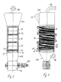
- FIG. 1 shows a schematic representation of a fluidized bed system 10 for conditioning fluidizable, free-flowing bulk materials, such as granulated sugar, fertilizer or the like.
- the device 10 has an inlet 11 for product delivery.
- the inlet 11 is arranged at the upper end of the system 10.
- a process space 12 is formed, in which the bulk material is fluidized.
- an outlet 13 for the product outlet in the conditioned state is provided below the process space 12, an outlet 13 for the product outlet in the conditioned state is provided below the outlet 13 a discharge lock 14 is provided, which is driven by a motor and ensures a product discharge under pressure.
- packages 15, 16, 17 of heat exchanger elements 171 are arranged, in which the heat transfer elements 171 are present in the form of tubular bodies, which are flowed through by a heat transfer medium, for example, cooled or heated liquid or cooled or heated gas.
- a heat transfer medium for example, cooled or heated liquid or cooled or heated gas.
- the packages 15, 16, 17 are supplied by the heat transfer medium via a supply line 21 with the heat transfer medium.
- the heat transfer medium passes through all packages 15, 16, 17 of heat transfer elements from bottom to top and is then passed via a return line 22 to a kind of cooling or heating station.
- all packages 15, 16, 17 of heat exchanger elements 171 can be supplied separately with a heat transfer medium.
- cooled fluid is introduced through the supply line 21 into the packages 15, 16, 17 of heat transfer elements.
- process gas is introduced into the process space through the lower boundary 50 at a recycle gas inlet point 181.
- the process gas is, like the heat transfer medium, also passed in countercurrent through the process chamber 12 and simultaneously cools or dries the bulk material, such as granulated sugar.
- the heat exchanger elements 171 within the packages 15, 16, 17 of heat exchanger elements additionally ensure a homogenization of the air flow within the process chamber 12 as well as an avoidance of blistering, which occurs or can occur especially in fine-grained bulk solids.
- a return line 18 is arranged at a process gas outlet 182, so that the recycle gas can be returned to the fan 20. If exhaust gases occur, they are discharged through a drain 180 from the process. Within the return line 18, a conditioning or conditioning unit for the process gas can be switched on.
- fresh process gas 19 is introduced into the return line 18.
- a load cell 40 measures the pressure and other parameters of the fresh gas.
- a pressure measuring unit 30 measures the pressure in the region of the lower limit 50 at the lower end of the process space. If a critical value is reached, an actuator 60 is put into operation via an integrated control unit, which increases or reduces the free cross-sectional areas 55 within the lower limit 50, by lowering or raising the levels 51, 52, not shown, of the lower boundary 50. This serves to control the product pass. In this case, the openings within the lower boundary 50 are not completely closed, so that process gas can pass through, but the passage cross-section is chosen so that the bulk material can not fall through. If a certain level within the process chamber 12 is reached, the pressure loss within the process chamber 12 due to the bulk material therein is so great that the pressure measuring unit 30 determines a corresponding value and then increases the free passage cross-sections. As a result, the bulk material moves through the free cross-sectional areas 55 within the lower boundary 50 and is conveyed through the discharge lock 14 to the outlet and transported away therefrom.
- FIG. 2 is an exploded perspective view.
- the device 10 is partially shown and shows an upper part 101 and a lower part 102 with an inlet 11 and an outlet 13.
- the process gas is introduced through the process gas inlet 181, which is arranged on the lower part 102 and discharged through the process gas outlet 182 on the upper part 101 .
- a package 17 of heat exchanger elements with a plurality of tubular, each other vertically and horizontally offset heat transfer elements 171 is arranged between the upper part 101 and the lower part 102.
- a feed line 21 and a return line 22 provide for the supply and removal of the heat transfer medium, which is passed in countercurrent, ie from bottom to top through the package 17 of heat transfer elements.
- the process space 12 Shooting sidewalls are not shown for clarity.
- a lower boundary 50 which consists of two levels 51, 52. These levels are formed by roof-shaped profiles 1, 2, whose arrangement in FIG. 5 is shown and will be discussed later.
- the two levels 51, 52 are mutually displaceable, in the present embodiment, the lower level 51 can be lowered down, while the upper level 52 is fixed.
- the upper level 52 consists of roof-shaped, spaced-apart longitudinal profiles 2. This prevents that the bulk material remains lying on the profiles 1, 2.
- FIGS. 3 and 4 which show a section of various orientations along the vertical axis of the device 10, it can be seen that the packages 15, 16, 17 of heat transfer elements 171 have separate supply ports and discharge ports.
- the plurality of heat exchanger elements 171 which are arranged substantially horizontally and are arranged transversely to the flow direction of the process gas and to the passage direction of the bulk material, can be recognized.
- the bulk material comes into intensive contact with both the heat transfer elements 171 and with the process gas.
- the bulk material is swirled in countercurrent;
- a heat transfer and optionally a mass transfer is carried out so that the bulk material is dehumidified or moistened.
- FIGS. 3 and 4 to recognize the roof-shaped embodiments of the lower level 51 and the upper level 52 with a steeper roof-shaped structure.
- pneumatic actuators 60 are arranged, which can be lowered to increase the flow cross-section or the free cross-sectional areas 55 within the lower boundary 50.
- the lower level 51 of the profiles is lowered, the gap between the profiles of the lower level 51 and the upper level 52 is increased and a larger flow of bulk material is passed through.
- the structure of the levels 51, 52 and the lower limit 50 is in the FIG. 5 in which a detail of the lower limit 50 is shown.
- the upper level 52 is formed by a plurality of parallel, roof-shaped profiles 2, which are arranged spaced from each other. These profiles 2 are preferably fixedly arranged on the lower boundary of the process space 12. Alternatively, these profiles 2 can be designed to be movable.
- the lower level 51 is arranged with a plurality of slightly roof-shaped profiles 1, which are held by a rail 3 at a fixed distance from each other. The distances can be adjustable. Below this rail 3, the actuators 60 are arranged in the FIG. 5 are not shown.
- the respective profiles 1, 2 are offset from each other and spaced apart within the plane 51, 52, so that the free spaces formed between the respective profiles 1, 2 in the respective plane 51, 52 are covered by the underlying or overlying plane.
- the angle of the roof-shaped profiles 1 is chosen so that no bulk material remains on the surface.
- Between the planes 51, 52 may be provided a permanent distance a, for example, ensured by spacer elements, so that always a minimum amount of process gas can flow through the lower boundary 50 therethrough.
- the distance a is chosen so that the bulk material can not pass through the flow opening, which is formed by the spacing of the two planes 51, 52 to each other.
- the lower level 51 is lowered via a control device 30 and the flow cross section and the passage cross section between the levels 51, 52 enlarged.
- the passage rate is increased if a continuous process takes place, or allows the bulk material to escape during batchwise process control.
- the entire product, including any resulting dusts, is passed through the free cross-sectional areas 55 transported and falls down into the funnel-shaped lower part 102.
- the product passing through eliminates any existing contamination in the free cross-sectional areas 55 due to the abrasive effects of the bulk material.
- the inflow velocity of the process gas in the process chamber 12 is below the speed at which the bulk material would be discharged upward, preferably at a value between the vortex point speed and the half of Einzelkornsink Malawi a bulk material grain with average particle diameter.
- tilting of the levels 51, 52 relative to each other can take place in order to change the size of the free cross-sectional areas 55. It is also possible, in an alternative embodiment, to change the free cross-sectional areas 55 by a displacement in the horizontal plane in order to discharge the bulk material through the lower boundary 50 from the process space 12.
- a displacement in the horizontal plane in order to discharge the bulk material through the lower boundary 50 from the process space 12.
- pyramidal elements may be provided as upper or lower level.
- the amount of fresh gas is such that the optionally desired mass transfer, z. B. drying, is possible.
- the feeding of the bulk material takes place in the upper part 101 of the device 10, which is preferably under a slight negative pressure. If an internal dedusting be provided, a dedusting device, such as a cyclone, also within the upper part 101, which is designed as a hood arranged.
- the free cross-sectional areas 55 clean themselves so that dust-containing gas can be supplied to the fluidized bed without the free cross-sectional areas 55 becoming clogged.
- the cross section is chosen so that the angle of repose of the bulk material prevents leakage of the bulk material.
- the size of the free cross-sectional areas 55 can be adapted to the grain size of the respective product.
- FIG. 6 which has an enlarged section of the FIG. 3 represents, the arrangement of the individual profiles 1, 2 can be seen in the respective planes 51, 52.
- the lower level 51 of the profiles 1 is mounted on a common rail 3 and can be changed via the actuator 60, in this case a pneumatic cylinder, in the vertical position. This is indicated by the double arrow.
- the actuator 60 in this case a pneumatic cylinder, in the vertical position.
- the likewise elongated free cross-sectional areas 55 are formed through which both the process gas flow from bottom to top and the bulk material can pass from top to bottom.
- a package 17 of heat exchanger elements 171 with a plurality of heat exchanger elements 171 is shown above the lower boundary 50.
- the individual heat exchanger elements 171 are arranged substantially horizontally and can extend parallel to one another and offset relative to one another, alternatively or additionally, the heat exchanger elements 171 can also be arranged so as to be oriented horizontally in a horizontal orientation.
- each element 1 or profile 1 can be individually couple with an actuator 60 to lower or raise these individually or in groups.
- the planes 51, 52 can be rotated, shifted or tilted relative to each other. It is also possible to move the individual elements or profiles 1, 2 to each other, to twist or tilt, to cause changes in the free cross-sectional areas 55 to the desired extent.
Abstract
Description
Die Erfindung betrifft eine Vorrichtung und ein Verfahren zum Konditionieren rieselfähiger, fluidisierbarer Festkörper gemäß den Oberbegriffen der Ansprüche 1 und 15.The invention relates to an apparatus and a method for conditioning free-flowing, fluidizable solids according to the preambles of
Bei der Herstellung und Verarbeitung rieselfähiger, fluidisierbarer Schüttgüter werden diese einer Vielzahl verfahrenstechnischer Operationen unterworfen. Zur Lagerung, Verpackung oder zum Einleiten nachfolgender Verfahrensschritte ist es vielfach notwendig, diese Schüttgüter zu konditionieren, beispielsweise zu kühlen, zu entfeuchten oder dergleichen. Insbesondere zum Einlagern von Schüttgütern ist es notwendig, dass sowohl deren Temperatur als auch deren Feuchtegehalt korrekt eingestellt wird, beispielsweise um ein Verderben der Produkte oder eine Agglomeration der Schüttgüter zu vermeiden. Ebenfalls kann es notwendig sein, dass die jeweiligen Schüttgüter erwärmt werden müssen.In the production and processing of free-flowing, fluidisable bulk materials, these are subjected to a large number of process engineering operations. For storage, packaging or to initiate subsequent process steps, it is often necessary to condition these bulk materials, for example, to cool, dehumidify or the like. In particular, for storing bulk materials, it is necessary that both their temperature and their moisture content is adjusted correctly, for example, to prevent spoilage of the products or agglomeration of the bulk materials. It may also be necessary that the respective bulk materials must be heated.
Zur Konditionierung körniger Schüttgüter ist es bekannt, dass die Schüttgüter in Kontakt mit einem gasförmigen Medium gebracht werden, wodurch der Wärmeübergang erfolgt. Die dadurch erreichte Temperaturdifferenz des gasförmigen Mediums und die Menge des Mediums bestimmen die übertragene Wärmemenge. Da die Wärmekapazität von Gasen gering ist und die zur Verfügung stehende Temperaturdifferenz insbesondere zum Kühlen begrenzt ist, werden für dieses Verfahren oft erhebliche Gasmengen benötigt. Der Wärmeübergang wird häufig auch in Kombination mit einem Stoffübergang benutzt, so dass das Schüttgut getrocknet wird. Darüber hinaus kommt es zu einem Austrag von Staub und kleiner Partikel, so dass Entstaubungsanlagen zwingend einzubauen sind. Trommelkühler oder Wirbelschichtapparate ohne Einbauten sind Beispiele für solche Konditioniereinrichtungen.For the conditioning of granular bulk materials, it is known that the bulk materials are brought into contact with a gaseous medium, whereby the Heat transfer occurs. The resulting temperature difference of the gaseous medium and the amount of the medium determine the amount of heat transferred. Since the heat capacity of gases is low and the available temperature difference is limited in particular for cooling, this method often requires significant amounts of gas. The heat transfer is often used in combination with a mass transfer, so that the bulk material is dried. In addition, there is a discharge of dust and small particles, so that dedusting plants are mandatory to install. Drum coolers or fluidized bed apparatus without internals are examples of such conditioning equipment.
Eine weitere Möglichkeit zur Konditionierung körniger Schüttgüter besteht darin, diese in direktem Kontakt mit Wärmeübergangsflächen zu bringen. Diese Wärmeübergangsflächen werden von einem Wärmeträgermedium durchströmt, so dass das Schüttgut von dem Wärmeträgermedium räumlich getrennt bleibt. Die Wärmeübergangszahlen sind im Vergleich zu einem umströmenden Kontakt mit dem Wärmeträgermedium gering, da die Kontaktfläche geringer ist und nur auf die Berührungsflächen begrenzt ist. Darüber hinaus ist der erlaubte Temperaturunterschied zwischen dem Schüttgut und den Wärmeübergangsflächen durch die Produkteigenschaften des Schüttgutes limitiert.Another way to condition granular bulk materials is to bring them in direct contact with heat transfer surfaces. These heat transfer surfaces are flowed through by a heat transfer medium, so that the bulk material remains spatially separated from the heat transfer medium. The heat transfer coefficients are low in comparison to a flowing contact with the heat transfer medium, since the contact surface is smaller and limited only to the contact surfaces. In addition, the permitted temperature difference between the bulk material and the heat transfer surfaces is limited by the product properties of the bulk material.
Aufgrund einer vorhandenen Relativbewegung zwischen den Wärmeübergangsflächen und dem Schüttgut kann es zudem zu einem Abrieb des Schüttgutes kommen. Die
Eine zusätzliche Möglichkeit zur Konditionierung körniger Schüttgüter besteht in einer Kombination aus direktem und indirektem Wärmeübergang. Die
Um die erforderliche Wärmeübergangsflächen zur Verfügung stellen zu können, müssen mehrere Sektionen horizontal nebeneinander angeordnet werden, da die maximale Höhe der Wirbelschicht wegen der notwendigen, gleichmäßigen Verweilzeitverteilung der Feststoffpartikel beim Durchlauf durch den Apparat begrenzt ist. Damit der Produkttransport funktioniert, muss ein nicht unerheblicher Druckverlust durch den Gasverteil- oder Anströmboden aufgebracht werden. Die Gasgeschwindigkeit in der Wirbelschicht muss dabei so eingestellt werden, dass sie etwa 6- 7 Mal so groß ist wie die Gasgeschwindigkeit, bei der die Schüttung zu wirbeln beginnt. Der Gasverteil- oder Anströmboden besteht aus gelochten Blechen. Die Löcher müssen so klein gewählt werden, dass kein Produkt hindurch fällt. Dadurch werden sie anfällig gegen Zusetzungen durch Verschmutzungen, wodurch die Fluidisierung verschlechtert und der Feststofftransport behindert wird. Ist eine zu große Anzahl an freie Querschnittflächen verstopft, müssen die Gasverteilböden aufwendig gereinigt werden. Um das Zusetzen der freie Querschnittflächen weitestgehend zu vermeiden, muss das Prozessgas aufwendig entstaubt werden. Aufgrund der hohen Gasmenge, die zum Erreichen einer Fluidisierung und einem Stofftransport notwendig ist, ist die Aufbereitung des Prozessgases außerordentlich aufwendig.In order to provide the required heat transfer surfaces available, several sections must be arranged horizontally next to each other, since the maximum height of the fluidized bed is limited because of the necessary, uniform residence time distribution of the solid particles as they pass through the apparatus. In order for the product transport to work, a considerable pressure loss must be applied through the gas distributor or distributor plate. The gas velocity in the fluidized bed must be set to be approximately 6-7 times the gas velocity at which the bed begins to whirl. The Gasverteil- or distributor bottom consists of perforated plates. The holes must be chosen so small that no product falls through. As a result, they become susceptible to contamination by contamination, whereby the fluidization deteriorates and the transport of solids is hindered. If too large a number of free cross-sectional areas are clogged, the gas distribution trays must be thoroughly cleaned. To avoid the clogging of the free cross-sectional areas as far as possible, the process gas must be dedusted consuming. Due to the high amount of gas required to achieve a fluidization and a Mass transport is necessary, the treatment of the process gas is extremely expensive.
Die
Aufgabe der vorliegenden Erfindung ist es, eine Vorrichtung und ein Verfahren bereitzustellen, mit denen bei Einsatz einer minimalen Gasmenge zur Fluidisierung des Schüttgutes eine hohe Effizienz des Wärme- und gegebenenfalls Stoffüberganges erreicht und eine zuverlässige Prozessführung gewährleistet werden.The object of the present invention is to provide a device and a method with which, when using a minimum amount of gas for fluidizing the bulk material, a high efficiency of the heat and optionally mass transfer can be achieved and reliable process control can be ensured.
Erfindungsgemäß wird diese Aufgabe durch eine Vorrichtung mit den Merkmalen des Anspruchs 1 sowie ein Verfahren nach den Merkmalen des Anspruchs 15 gelöst. Vorteilhafte Ausgestaltungen und Weiterbildungen der Erfindung sind in den jeweiligen Unteransprüchen angeführt.According to the invention this object is achieved by a device having the features of claim 1 and a method according to the features of
Die Vorrichtung zur Konditionierung rieselfähiger, fluidisierbarer Schüttgüter mit einem Prozessbehälter, der einen Einlass zur Zufuhr des Schüttgutes und einen unterhalb des Einlasses angeordneten Auslass zum Austrag der Festkörper aufweist, wobei der Prozessbehälter einen unterhalb des Einlasses angeordneten Prozessraum mit zumindest einem darin angeordneten Wärmeübertragerelement aufweist, das von einem gasförmigen oder flüssigen Medium durchströmbar ist und bei dem unterhalb des oder der Wärmeübertragerelemente eine untere Begrenzung mit Öffnungen angeordnet ist, durch den ein Prozessgas von unten in den Prozessraum einleitbar ist, sieht eine untere Begrenzung vor, die eine obere Ebene und eine untere Ebene aufweist, die zumindest teilweise relativ zueinander verlagerbar sind und die freie Querschnittflächen veränderlicher Größe ausbilden. Durch die bewegliche Ausgestaltung der beiden Ebenen insgesamt oder von Teilen der Ebenen zueinander, die gemeinsam die untere Begrenzung oder einen Teil der untern Begrenzung des Prozessraumes bilden, ist es möglich, eine Anpassung der Vorrichtung einerseits an die erforderlichen Konditionierungsaufgaben und andererseits an die gegebenen Eigenschaften des Schüttgutes wie Partikelgröße, Partikelgrößenverteilung, Klebrigkeit etc. vorzunehmen. Je nach Art und Menge des vorhandenen Prozessgases ist es möglich, eine Anpassung der Größe der freien Querschnittflächen vorzunehmen. Ebenfalls besteht die Möglichkeit, dass im Falle von zugesetzten freien Querschnittflächen diese vergrößert werden, so dass durchströmendes Schüttgut die Anlagerungen beseitigt. Der Transport des Schüttgutes erfolgt dabei anders als bei den üblichen Wirbelschichttrocknern oder Wirbelschichtkühlern in Richtung der Gravitation von oben nach unten mit einem Auslass unterhalb der unteren Begrenzung des Prozessraumes. Hierbei ist die im Gegenstrom geführte Prozessgasmenge im Vergleich zu herkömmlichen Wirbelschichtanlagen deutlich kleiner. Das Schüttgut tritt somit durch die untere Begrenzung nach unten hindurch und verlässt die Vorrichtung durch einen Auslass, der unterhalb des eigentlichen Prozessraumes liegt, in dem die Konditionierung erfolgt. Die freien Querschnittflächen dienen somit gleichzeitig für den Prozessgasdurchgang als auch für den Feststoffdurchgang. Die Bezeichnungen "oben" und "unten" sind dabei in der üblichen Bedeutung in Bezug auf die Gravitationsrichtung zu verstehen.The apparatus for conditioning flowable, fluidizable bulk materials having a process container having an inlet for supplying the bulk material and an outlet arranged below the inlet for discharging the solids, the process container having a process space arranged below the inlet with at least one heat transfer element arranged therein can be traversed by a gaseous or liquid medium and in which below the heat exchanger or a lower boundary is arranged with openings through which a process gas from below into the process chamber can be introduced, provides a lower boundary, which is an upper level and a lower level which are at least partially displaceable relative to each other and form the free cross-sectional areas of variable size. Due to the movable design of the two levels in total or parts of the planes to each other, which together form the lower boundary or part of the lower boundary of the process space, it is possible to adapt the Device on the one hand to the required conditioning tasks and on the other hand to the given properties of the bulk material such as particle size, particle size distribution, stickiness etc. make. Depending on the type and amount of the existing process gas, it is possible to make an adjustment of the size of the free cross-sectional areas. It is also possible that in the case of added free cross-sectional areas they are increased so that flowing bulk material eliminates the deposits. The transport of the bulk material takes place differently than in the conventional fluidized bed dryers or fluidized bed coolers in the direction of gravity from top to bottom with an outlet below the lower boundary of the process chamber. Here, the countercurrent process gas quantity is much smaller compared to conventional fluidized bed plants. The bulk material thus passes down through the lower boundary and exits the device through an outlet which is below the actual process space in which the conditioning takes place. The free cross-sectional areas thus serve simultaneously for the process gas passage as well as for the solids passage. The terms "top" and "bottom" are to be understood in the usual meaning with respect to the direction of gravity.
Eine Weiterbildung der Erfindung sieht vor, dass die untere Ebene der unteren Begrenzung des Prozessraumes ganz oder teilweise absenkbar ist, so dass die untere Ebene oder Teile oder Elemente davon von der oberen Ebene gesehen jenseits des Schüttgutes liegt oder liegen. Durch das Absenken der unteren Ebene können die freien Querschnittsflächen, durch die sowohl das Prozessgas als auch das Schüttgut hindurch treten, in ihrer Größe verändert werden. Beim Absenken werden die freien Querschnittsflächen vergrößert. Selbstverständlich ist es vorgesehen, dass umgekehrt zur Verkleinerung der freien Querschnittflächen bzw. des Strömungs- oder Durchtrittsquerschnittes die Ebene angehoben wird. Neben einer Verlagerbarkeit der ersten Ebene in oder entgegen der Gasströmungsrichtung ist es möglich, diese verschiebbar zu gestalten, um dadurch die Strömungs- und Durchtrittsquerschnitte zu vergrößern oder zu verkleinern. Die obere Ebene ist dabei bevorzugt starr an der unteren Begrenzung des Prozessraumes angeordnet, um eine möglichst leichte Zuordnung der Ebenen zueinander zu gewährleisten. Grundsätzlich ist es möglich, dass beide Ebenen beweglich verlagerbar im Bereich der unteren Begrenzung des Prozessraumes gelagert sind und durch eine entsprechende Aktuierung in ihrer Position verändert werden können. Beispielsweise können die Ebenen zueinander kippbar oder drehbar gelagert sein. Eine Verlagerung der Ebenen zueinander kann manuell oder motorisch, insbesondere pneumatisch erfolgen. Besteht eine der Ebenen aus mehreren Komponenten oder Elementen können diese einzeln oder in Gruppen verfahrbar ausgestaltet sein, um so über die Fläche der unteren Begrenzung des Prozessraumes verteilt unterschiedliche Querschnitte der freien Querschnittflächen bereitzustellen.A development of the invention provides that the lower level of the lower boundary of the process space is completely or partially lowered, so that the lower level or parts or elements thereof seen from the upper level is beyond the bulk material or lie. By lowering the lower level, the free cross-sectional areas, through which both the process gas and the bulk material pass through, can be changed in size. When lowering the free cross-sectional areas are increased. Of course, it is provided that, conversely, to reduce the size of the free cross-sectional areas or of the flow or passage cross-section, the plane is raised. In addition to a displaceability of the first plane in or against the gas flow direction, it is possible to make these displaceable, thereby increasing or decreasing the flow and passage cross-sections. The upper level is preferably arranged rigidly at the lower boundary of the process space in order to ensure the easiest possible assignment of the levels to one another. in principle it is possible that both levels are movably displaced in the region of the lower boundary of the process space and can be changed by a corresponding actuation in position. For example, the planes may be tiltable or rotatable relative to each other. A displacement of the planes to each other can be done manually or by motor, in particular pneumatically. If one of the levels consists of several components or elements, these can be designed to be movable individually or in groups so as to provide different cross sections of the free cross-sectional areas distributed over the area of the lower boundary of the process space.
In einer vorteilhaften Ausgestaltung der Erfindung ist vorgesehen, dass die obere Ebene aus dachförmigen Elementen, insbesondere langgestreckten Profilen ausgebildet sind, die zueinander beabstandet angeordnet sind. Die dachförmige Ausgestaltung der Profile verhindert eine Anlagerung von Schüttgutpartikeln auf der Oberfläche der oberen Ebene, da die Partikel oder Festkörperteilchen entlang der schrägen Flächen herunterrutschen. Weiterhin erhöht die dachförmige Profilanordnung die Stabilität der Elemente in der oberen Ebene.In an advantageous embodiment of the invention it is provided that the upper level of roof-shaped elements, in particular elongated profiles are formed, which are arranged spaced from each other. The roof-shaped configuration of the profiles prevents an accumulation of bulk particles on the surface of the upper level, since the particles or solid particles slide down along the inclined surfaces. Furthermore, the roof-shaped profile arrangement increases the stability of the elements in the upper level.
Die untere Ebene kann ebenfalls aus dachförmigen Elementen ausgebildet sein, bevorzugt mit einem flachen Dachwinkel. Dabei sind die unterhalb der oberen Ebene angeordneten dachförmigen Elemente so dimensioniert, dass sie in Strömungsrichtung gesehen die Zwischenräume zwischen den Elementen der oberen Ebene abdecken, also versetzt zu den Profilen oder Elementen der oberen Ebene angeordnet sind. In der Projektion ist dadurch eine insgesamt geschlossene untere Begrenzung des Prozessraumes ausgebildet, die freien Querschnittsflächen zum Durchströmen oder Durchtreten von Prozessgas und Schüttgut werden durch einen Abstand der Elemente zueinander ausgebildet, so dass der Prozessgas- und der Schüttgutstrom eine Richtungsablenkung erfahren. Durch die Überdeckung ist es möglich, dass die untere Begrenzung des Prozessraumes komplett geschlossen sein kann oder die Ebenen so zueinander angeordnet werden können, dass ein minimaler Spalt bzw. eine minimale freie Querschnittfläche vorhanden ist, durch die das Prozessgas hindurch strömen kann, das Schüttgut jedoch aufgrund der Partikelgröße oder des Schüttwinkels nicht hindurchtreten kann. Die dachförmigen oder anders ausgebildeten Elemente der unteren Ebene können einzeln, in Gruppen oder gemeinsam relativ zu der oberen Ebene verlagert, insbesondere abgesenkt oder angehoben werden, um die gewünschten Effekte innerhalb des Prozessraumes zu erreichen. Dazu können die einzelnen Elemente oder Profile jeweils mit einem Aktuator gekoppelt sein, durch den eine Einzelansteuerung möglich ist.The lower level may also be formed of roof-shaped elements, preferably with a flat roof angle. Here, the arranged below the upper level roof-shaped elements are dimensioned so that they cover the spaces between the elements of the upper level seen in the flow direction, that are offset from the profiles or elements of the upper level. As a result, an overall closed lower boundary of the process space is formed in the projection, the free cross-sectional areas for flowing through or passing through process gas and bulk material are formed by a distance of the elements from one another, so that the process gas flow and the bulk material flow undergo a directional deflection. As a result of the overlapping, it is possible for the lower boundary of the process space to be completely closed or for the planes to be arranged relative to one another in such a way that there is a minimal gap or a minimum free cross-sectional area through which the process gas can flow, but the bulk material can not pass due to the particle size or the angle of repose. The roof-shaped or otherwise formed lower-level elements may be individually, in groups or jointly displaced relative to the upper level, in particular lowered or raised in order to achieve the desired effects within the process space. For this purpose, the individual elements or profiles can each be coupled to an actuator by which a single control is possible.
Um zu gewährleisten, dass stets ein minimaler Gasstrom durch die freien Querschnittsflächen und Öffnungen in den Ebenen hindurchtreten kann, ist in einer Weiterbildung vorgesehen, dass zwischen der unteren und der oberen Ebene bzw. zwischen den Elementen der Ebenen Abstandshalter angeordnet sind, die bei einem Verfahren der Ebenen oder Elementen aufeinander zu einen mechanischen Anschlag bilden. Werden die freien Querschnittflächen vergrößert, also über dasjenige Maß hinaus, in dem der Schüttwinkel des Schüttgutes ein Austreten durch die freie Querschnittflächen verhindert, kommt es zu dem gewünschten Effekt, dass die Öffnungen durch das durchtretende Schüttgut selbst gereinigt werden, so dass es auch möglich ist, staubhaltiges Gas der Schüttgutschicht zuzuführen, ohne dass die freien Querschnittsflächen sich zusetzen und die untere Begrenzung verschließen. Ein Selbstreinigungseffekt tritt ein, sobald das Schüttgut gravitationsgetrieben entgegen dem Gasstrom durch die freien Querschnittsflächen hindurchtritt. Die Verstellbarkeit der freien Querschnittsflächen ermöglicht auch das Verarbeiten von Schüttgütern unterschiedlicher Körnungen.In order to ensure that a minimum gas flow can always pass through the free cross-sectional areas and openings in the planes, it is provided in a development that spacers are arranged between the lower and the upper level or between the elements of the levels, which in one method of the planes or elements towards each other form a mechanical stop. If the free cross-sectional areas are increased, ie beyond that level in which the angle of repose of the bulk material prevents leakage through the free cross-sectional areas, the result is that the openings themselves are cleaned by the passing bulk material, so that it is also possible to supply dusty gas to the bulk material layer without the free cross-sectional areas becoming clogged and closing the lower boundary. A self-cleaning effect occurs as soon as the bulk material passes gravitationally against the gas flow through the free cross-sectional areas. The adjustability of the free cross-sectional areas also allows the processing of bulk materials of different grain sizes.
Eine Weiterbildung sieht vor, dass mehrere Wärmeübertragerelemente übereinander angeordnet sind, die separat von einem Wärmeträgermedium durchströmt sind. Dadurch können unterschiedliche Wärmeübergangsgrade bzw. Temperaturgradienten eingestellt werden. Die Wärmeübertragerelemente, die auch in Paketen von Wärmeübertragerelementen angeordnet sein können, sind insbesondere senkrecht zur Gasdurchströmungsrichtung angeordnet, also vorwiegend horizontal, und bestehen aus einer Vielzahl nebeneinander und übereinander angeordneter, fluiddurchströmter Rohrkörper oder Rohrkörperabschnitte eines Wärmeübertragerelementes. Die Wärmeübertragerelemente sind als eine Vielzahl einzelner Rohrkörper oder als ein mäanderartig gebogenes Rohr ausgebildet, die oder das von einem Wärmeträgermedium, z.B. Gas oder Flüssigkeit, durchströmt ist. Die einzelnen Wärmeübertragerelemente sind horizontal beabstandet zueinander ausgebildet, um Schüttgut und Prozessgas von oben nach unten und umgekehrt durch den Prozessraum hindurchtreten zu lassen. Sind mehrere Lagen an Wärmeübertragerelementen übereinander angeordnet, so sind sie bevorzugt versetzt zueinander angeordnet, so dass die Wärmeübertragerelemente der unteren Ebene unter den Zwischenräumen der Wärmeübertragerelemente der nächsthöheren Ebene liegen. Einzelne Wärmeübertragerelemente können zu Paketen von Wärmeübertragerelementen zusammengefasst sein.A further embodiment provides that a plurality of heat exchanger elements are arranged one above the other, which are flowed through separately by a heat transfer medium. As a result, different heat transfer grades or temperature gradients can be set. The heat transfer elements, which may also be arranged in packages of heat transfer elements, are arranged in particular perpendicular to the gas flow direction, ie predominantly horizontally, and consist of a plurality of juxtaposed and superimposed, fluid-flowed tubular body or tube body sections of a heat transfer element. The heat transfer elements are formed as a plurality of individual tubular body or as a meander-like bent tube, or the one of a Heat transfer medium, such as gas or liquid, is flowed through. The individual heat exchanger elements are formed horizontally spaced from each other to allow bulk material and process gas to pass from top to bottom and vice versa through the process space. If a plurality of layers of heat transfer elements are arranged one above the other, then they are preferably offset relative to one another so that the heat transfer elements of the lower level are below the interstices of the heat transfer elements of the next higher level. Individual heat exchanger elements can be combined to form packages of heat exchanger elements.
Durch die Anordnung der Wärmeübertragerelemente oder Rohrkörper innerhalb des Prozessraumes wird die Gasströmung und das Fließverhalten des fluidisierten Schüttgutes vergleichmäßigt, so dass insbesondere bei feinkörnigen Schüttgütern eine Blasenbildung und eruptives Hindurchtreten des Prozessgases durch die Schüttschicht vermieden wird. Die vertikale Anordnung der Wärmeübertragerelemente oder -pakete ermöglicht eine platzsparende Konstruktion, die einen geringen Grundflächenbedarf hat und nur durch die Bauhöhe limitiert ist.The arrangement of the heat transfer elements or tubular body within the process chamber, the gas flow and the flow behavior of the fluidized bulk material is made uniform, so that especially in fine-grained bulk solids blistering and eruptive passage of the process gas through the packed layer is avoided. The vertical arrangement of the heat exchanger elements or packages allows a space-saving design, which has a small footprint and is limited only by the height.
Eine Weiterbildung der Erfindung sieht vor, dass an dem oberen Ende des Prozessraumes eine Rückführleitung für das Prozessgas angeordnet ist, die das Prozessgas zu einem Ventilator oder Kompressor zurückführt. Zur Beschleunigung des Prozessgases können unterschiedliche Vorrichtungen eingesetzt werden, insbesondere werden Drehkolbengebläse oder Radialventilatoren vorgesehen. Aufgrund der Selbstreinigungsfähgigkeit der Vorrichtung kann auch ein nicht entstaubtes Prozessgas eingesetzt werden. Ebenfalls ist es möglich, dass eine Konditioniereinheit für das Prozessgas dem Ventilator oder Kompressor vorgeschaltet ist, so dass das Prozessgas gereinigt, entfeuchtet oder gegebenenfalls entstaubt wird. Die Konditioniereinheit kann das Prozessgas an die gewünschten Konditioniereigenschaften des Schüttgutes anpassen.A development of the invention provides that at the upper end of the process chamber, a return line for the process gas is arranged, which returns the process gas to a fan or compressor. To accelerate the process gas different devices can be used, in particular rotary blower or centrifugal fans are provided. Due to the self-cleaning capability of the device, it is also possible to use a non-dedusted process gas. It is also possible that a conditioning unit for the process gas is connected upstream of the fan or compressor, so that the process gas is cleaned, dehumidified or optionally dedusted. The conditioning unit can adapt the process gas to the desired conditioning properties of the bulk material.
Unterhalb des Prozessraumes ist eine Austragsschleuse angeordnet, durch die das durch den Prozessraum hindurchgeführte Schüttgut abtransportiert wird. Die Austragsschleuse gewährleistet einen Druckabschluss, so dass innerhalb des Prozessraumes ein kontrollierbarer Prozessdruck herrscht.Below the process space, a discharge lock is arranged, through which the bulk material passed through the process space is removed. The Discharge lock ensures a pressure seal, so that within the process chamber a controllable process pressure prevails.
Die untere Begrenzung des Prozessraumes ist so ausgebildet, dass der Schüttwinkel der Feststoffe einen Austritt bei geschlossenen Ebenen bzw. auch bei minimal beabstandeten Ebenen verhindert wird. Wird der Abstand vergrößert bzw. werden die freien Querschnittflächen vergrößert, ist es möglich, auch ohne Prozessgas bzw. Kreisgas einen Schüttguttransport zu gewährleisten, da die Partikel des Schüttgutes gravitationsgetrieben durch den Prozessraum hindurchtreten. Somit ist ein Ausbringen des Schüttgutes bei einem Ausfall der Lüfter möglich, so dass der Konditionierprozess auch bei einem Defekt nicht unterbrochen werden muss oder zumindest kontrolliert beendet werden kann.The lower boundary of the process chamber is designed so that the angle of repose of the solids is prevented from exiting at closed levels or even at minimally spaced levels. If the distance is increased or the free cross-sectional areas are increased, it is possible to ensure a bulk material transport even without process gas or recycle gas, since the particles of the bulk material pass through the process space gravitationally driven. Thus, a discharge of the bulk material in case of failure of the fan is possible, so that the conditioning process does not have to be interrupted even with a defect or at least can be stopped controlled.
Das erfindungsgemäße Verfahren zum Konditionieren, insbesondere Kühlen rieselfähiger, fluidisierbarer Schüttgüter in einem Prozessraum, in dem von oben das Schüttgut eingeführt und unterhalb einer unteren Begrenzung des Prozessraumes über einen Auslass ausgetragen wird, sieht vor, dass die untere Begrenzung des Prozessraumes freie Querschnittsflächen besitzt, die gleichzeitig für den Austrag des Schüttgutes nach unten und das Zuführen von Prozessgas im Gegenstrom nach oben in den Prozessraum genutzt werden, wobei die freien Querschnittsflächen innerhalb der unteren Begrenzung in Abhängigkeit von einer Prozessgröße, insbesondere einem gemessenen Druck oder einem Füllstand, innerhalb des Prozessraumes vergrößert oder verkleinert werden. Die Durchtrittmenge des Schüttgutes wird durch ein bevorzugt periodisches Öffnen oder Schließen bzw. Vergrößern oder Verkleinern der freien Querschnittflächen innerhalb der unteren Begrenzung geregelt, mit dem Ziel, den Druck innerhalb der Schüttschicht oder Wirbelschicht oder den Füllstand konstant zu halten und einen gleichmäßigen Prozess mit gleichmäßigen Ergebnissen zu erhalten.The inventive method for conditioning, in particular cooling free-flowing, fluidizable bulk materials in a process space in which introduced from above the bulk material and discharged below a lower boundary of the process chamber via an outlet, provides that the lower boundary of the process chamber has free cross-sectional areas, the used simultaneously for the discharge of the bulk material down and the supply of process gas in countercurrent upward into the process space, wherein the free cross-sectional areas within the lower limit depending on a process variable, in particular a measured pressure or a level within the process space increased or be downsized. The flow rate of the bulk material is controlled by preferably periodically opening or closing or increasing or decreasing the free cross-sectional areas within the lower boundary, with the aim of keeping the pressure within the packed bed or fluidized bed or level constant and a smooth process with uniform results to obtain.
Bei einer druckbasierten Regelung ist der Druck innerhalb der Wirbelschicht proportional zu der Schüttgutmenge in der Wirbelschicht. Durch das z.B. periodische Öffnen und Schließen bzw. Vergrößern oder Verkleinern der Öffnungen innerhalb der unteren Begrenzung des Prozessraumes wird eine gleichmäßige Verteilung der Verweilzeit des Schüttgutes in der Vorrichtung erreicht, so dass ein gleichmäßiges Konditionierergebnis bei gleichzeitiger Gewährleistung eines sicheren Prozesses ermöglicht wird. Der Druckverlust der unteren Begrenzung, die aus einer festen Ebene mit dachförmigen Profilen bestehen kann, zwischen denen ein Abstand herrscht, ist wegen der relativ geringen Gasgeschwindigkeiten sehr gering. Die Gasverteilung erfolgt dabei vorrangig über die Schüttgutbewegung, durch die der Gasstrom gleichmäßig umgelenkt und über die gesamte Querschnittsfläche des Prozessraumes verteilt wird.In a pressure-based control, the pressure within the fluidized bed is proportional to the amount of bulk material in the fluidized bed. By eg periodic opening and closing or increasing or decreasing the openings within the lower boundary of the process space is a uniform distribution of Dwell time of the bulk material in the device achieved, so that a uniform Konditionierergebnis while ensuring a secure process is possible. The pressure loss of the lower boundary, which may consist of a fixed plane with roof-shaped profiles, between which there is a distance, is very low because of the relatively low gas velocities. The gas distribution takes place primarily via the bulk material movement, through which the gas flow is deflected uniformly and distributed over the entire cross-sectional area of the process space.
Das Prozessgas wird bevorzugt mit einer relativ geringen Geschwindigkeit in das Schüttgut eingeblasen, die zwischen der Wirbelpunktgeschwindigkeit des Schüttgutes und der Hälfte der Einzelkornsinkgeschwindigkeit des mittleren Partikeldurchmessers des Schüttgutes liegt, so dass es zu einer Wirbelbewegung innerhalb des Prozessraumes kommt. Im Bereich der Durchtrittsöffnungen werden durch Impulsaustausch nach unten abgelenkte fluidisierte Schüttgutpartikel in Richtung des Auslasses bewegt.The process gas is preferably injected into the bulk material at a relatively low velocity, which is between the vortex point velocity of the bulk material and half the Einzelkornsinkgeschwindigkeit the mean particle diameter of the bulk material, so that there is a whirling movement within the process space. In the area of the passage openings, fluidized bulk particles deflected downward by impulse exchange are moved in the direction of the outlet.
Das Prozessgas kann als Kreisgas geführt werden, wodurch eine Umweltbelastung vermieden oder verringert wird, wobei das Prozessgas vor dem Einblasen in die Schüttschicht konditioniert werden kann. Unter Konditionieren wird insbesondere das Reinigen, Kühlen bzw. Erwärmen oder auch Entfeuchten verstanden.The process gas can be conducted as cycle gas, whereby an environmental impact is avoided or reduced, wherein the process gas can be conditioned before blowing into the packed bed. By conditioning is meant in particular the cleaning, cooling or heating or dehumidifying.
Um Prozessgasverluste auszugleichen oder um die Beladung des Prozessgases mit Staub oder Feuchtigkeit nicht über einen kritischen Wert ansteigen zu lassen, kann konditioniertes Frischgas dem Kreisgas zugeführt werden.To compensate for process gas losses or to prevent the loading of the process gas with dust or moisture does not rise above a critical value, conditioned fresh gas can be supplied to the cycle gas.
Die Steuerung des Vergrößerns oder Verkleinerns der freien Querschnittflächen erfolgt über eine Parametermessung, insbesondere Füllstands- oder Druckbemessung innerhalb des Prozessraumes. Wird ein vorbestimmter Druck oder ein bestimmter Füllstand erreicht oder überschritten, werden die Öffnungen vergrößert. Die Dauer und die Intervallzeiten des Öffnens sind von dem gewünschten Durchsatz abhängig.The control of the enlargement or reduction of the free cross-sectional areas via a parameter measurement, in particular level or pressure measurement within the process space. If a predetermined pressure or a certain level is reached or exceeded, the openings are enlarged. The duration and the interval times of the opening depend on the desired throughput.
Ein bestimmter Druckwert wird gemessen, beispielsweise, wenn das Schüttgut den oberen Abschluss des Wärmeübertragerelementes bzw. der Pakete von Wärmeübertragerelementen erreicht hat. Ist dies der Fall, werden die freien Querschnittflächen vergrößert, beispielsweise durch Absenken der unteren Elementenebene oder Teilen davon. Werden der vorbestimmte Druck oder Füllstand unterschritten, werden die Querschnitte wieder verkleinert, bis der vorgegebene Druckwert oder Füllstandswert wieder erreicht wird.A certain pressure value is measured, for example, when the bulk material has reached the upper end of the heat transfer element or the packages of heat transfer elements. If this is the case, the free cross-sectional areas are increased, for example by lowering the lower element level or parts thereof. If the predetermined pressure or level falls below, the cross sections are reduced again until the predetermined pressure value or level value is reached again.
Das Konditionierverfahren kann sowohl kontinuierlich als auch chargenweise durchgeführt werden, wobei eine interne Entstaubung möglich ist, da nur geringe Luftmengen zur Konditionierung des Schüttgutes benötigt werden.The conditioning process can be carried out both continuously and batchwise, with an internal dedusting is possible because only small amounts of air for conditioning the bulk material are needed.
Nachfolgend wird ein Ausführungsbeispiel der Erfindung anhand der beigefügten Figuren näher erläutert. Es zeigen:
- Figur 1 -
- eine schematische Darstellung der Vorrichtung;
- Figur 2 -
- eine Explosionsdarstellung der Vorrichtung;
- Figur 3 -
- eine Längsschnittdarstellung der Vorrichtung;
- Figur 4 -
- eine Längsschnittdarstellung in einem anderen Winkel;
- Figur 5 -
- eine Detaildarstellung einer unteren Begrenzung; sowie
- Figur 6 -
- eine Detaildarstellung der
Figur 3
- FIG. 1 -
- a schematic representation of the device;
- FIG. 2 -
- an exploded view of the device;
- FIG. 3 -
- a longitudinal sectional view of the device;
- FIG. 4 -
- a longitudinal sectional view at a different angle;
- FIG. 5 -
- a detailed representation of a lower limit; such as
- FIG. 6 -
- a detailed view of the
FIG. 3 ,
Die Pakete 15, 16, 17 werden von dem Wärmeträgermedium über eine Zuführleitung 21 mit dem Wärmeträgermedium versorgt. In der dargestellten schematischen Anordnung durchläuft das Wärmeträgermedium sämtliche Pakete 15, 16, 17 von Wärmeübertragerelementen von unten nach oben und wird dann über eine Rückführleitung 22 zu einer Art Kühl- oder Aufheizstation geleitet. Alternativ dazu können sämtliche Pakete 15, 16, 17 von Wärmeübertragerelementen 171 separat mit einem Wärmeträgermedium versorgt werden.The
Soll beispielsweise das durch den Einlass 11 eingeführte Schüttgut gekühlt werden, wird gekühltes Fluid durch die Zuleitung 21 in die Pakete 15, 16, 17 von Wärmeübertragerelementen eingeführt. Gleichzeitig wird über einen Ventilator 20, der über einen Motor 201 angetrieben wird, an einer Kreisgaseinlassstelle 181 Prozessgas in den Prozessraum durch die untere Begrenzung 50 eingeleitet. Durch die gleichmäßig über den Querschnitt des Prozessraumes 12 verteilten freien Querschnittflächen 55 erfolgt eine gleichmäßige Beaufschlagung des Schüttgutes mit dem Prozessgas. Das Prozessgas wird, wie das Wärmeträgermedium, ebenfalls im Gegenstrom durch den Prozessraum 12 hindurch geleitet und kühlt bzw. trocknet gleichzeitig das Schüttgut, beispielsweise Kristallzucker. Durch den Gegenstrombetrieb stellt sich eine Fluidisierung des Schüttgutes innerhalb des Prozessraumes 12 ein, so dass sämtliche Schüttgutpartikel einerseits von dem Prozessgas durchströmt werden und andererseits in einen intensiven Kontakt mit den Wärmeübertragerelementen 171 innerhalb der Pakete 15, 16, 17 von Wärmeübertragerelementen geraten. Die Wärmeübertragerelemente 171 innerhalb der Pakete 15, 16, 17 von Wärmeübertragerelementen sorgen zusätzlich für eine Vergleichmäßigung der Luftströmung innerhalb des Prozessraumes 12 sowie für eine Vermeidung von Blasenbildung, die insbesondere bei feinkörnigen Schüttgütern auftritt bzw. auftreten kann.If, for example, the bulk material introduced through the
Am oberen Ende der Vorrichtung 10 ist an einem Prozessgasaustritt 182 eine Rückführleitung 18 angeordnet, damit das Kreisgas zum Ventilator 20 zurückgeführt werden kann. Sofern Abgase auftreten, werden die durch eine Ableitung 180 aus dem Prozess ausgeführt. Innerhalb der Rückführleitung 18 kann eine Konditionier- bzw. Aufbereitungseinheit für das Prozessgas eingeschaltet sein.At the upper end of the
Sofern frisches Prozessgas benötigt wird, wird Frischgas 19 in die Rückführleitung 18 eingeleitet. Eine Messdose 40 misst den Druck und andere Parameter des Frischgases.If fresh process gas is needed,
Eine Druckmesseinheit 30 misst am unteren Ende des Prozessraumes den Druck im Bereich der unteren Begrenzung 50. Wird ein kritischer Wert erreicht, wird über eine integrierte Steuereinheit ein Aktuator 60 in Betrieb genommen, der die freien Querschnittsflächen 55 innerhalb der unteren Begrenzung 50 vergrößert oder verkleinert, indem er die nicht dargestellten Ebenen 51, 52 der unteren Begrenzung 50 absenkt oder anhebt. Dies dient zur Steuerung des Produktdurchlaufes. Dabei sind die Öffnungen innerhalb der unteren Begrenzung 50 nicht vollständig geschlossen, so dass Prozessgas hindurchtreten kann, allerdings ist der Durchlassquerschnitt so gewählt, dass das Schüttgut nicht hindurch fallen kann. Wird ein gewisser Füllstand innerhalb des Prozessraumes 12 erreicht, ist der Druckverlust innerhalb des Prozessraumes 12 aufgrund des darin befindlichen Schüttgutes so groß, dass die Druckmesseinheit 30 einen entsprechenden Wert ermittelt und daraufhin die freien Durchtrittsquerschnitte vergrößert. Dadurch bewegt sich das Schüttgut durch die freien Querschnittflächen 55 innerhalb der unteren Begrenzung 50 und wird durch die Austragsschleuse 14 zum Auslass befördert und von dort abtransportiert.A
Einen detailierteren Aufbau zeigt die
In den Darstellungen 3 und 4, die einen Schnitt verschiedener Orientierungen entlang der Vertikalachse der Vorrichtung 10 zeigen, ist zu erkennen, dass die Pakete 15, 16, 17 von Wärmeübertragerelementen 171 separate Zufuhranschlüsse und Abfuhranschlüsse aufweisen. Ebenfalls sind die Vielzahl der Wärmeübertragerelemente 171, die im Wesentlichen horizontal angeordnet und quer zur Strömungsrichtung des Prozessgases und zur Durchlaufrichtung des Schüttgutes angeordnet sind, zu erkennen. Durch diese Anordnung, die sich über die gesamte Höhe und den gesamten Querschnitt des Prozessraumes 12 erstreckt, gelangt das Schüttgut in einen intensiven Kontakt sowohl mit den Wärmeübertragerelementen 171 als auch mit dem Prozessgas. Durch das Prozessgas wird das Schüttgut im Gegenstrom verwirbelt; weiter wird ein Wärmeübergang und gegebenenfalls ein Stoffübergang durchgeführt, so dass das Schüttgut entfeuchtet oder befeuchtet wird.In FIGS. 3 and 4, which show a section of various orientations along the vertical axis of the
Ebenfalls sind in den
Der Aufbau der Ebenen 51, 52 und der unteren Begrenzung 50 ist in der
Wird innerhalb des Prozessraumes 12 ein bestimmtes Druckniveau oder eine bestimmte Schichthöhe erreicht oder werden andere Produkt- oder Prozessparameter erreicht, beispielsweise die gewünschte Temperatur oder die gewünschte Trocknung, wird über eine Steuereinrichtung 30 die untere Ebene 51 abgesenkt und der Durchströmquerschnitt und der Durchtrittsquerschnitt zwischen den Ebenen 51, 52 vergrößert. Dadurch wird die Durchtrittsmenge erhöht, sofern ein kontinuierlicher Prozess abläuft, oder ein Austreten des Schüttgutes bei einer chargenweisen Prozessführung ermöglicht. Das gesamte Produkt, einschließlich eventuell anfallender Stäube, wird durch die freien Querschnittflächen 55 hindurch transportiert und fällt nach unten in das trichterförmig ausgebildete Unterteil 102. Durch das hindurchtretende Produkt werden eventuell vorhandene Verschmutzungen in den freien Querschnittflächen 55 aufgrund der abrasiven Effekte des Schüttgutes beseitigt. Die Anströmgeschwindigkeit des Prozessgases in dem Prozessraum 12 liegt dabei unterhalb der Geschwindigkeit, bei der das Schüttgut nach oben ausgetragen werden würde, bevorzugt bei einem Wert zwischen der Wirbelpunktgeschwindigkeit und der Hälfte der Einzelkornsinkgeschwindigkeit eines Schüttgutkornes mit mittlerem Partikeldurchmesser.If a specific pressure level or a certain layer height is reached within the
Alternativ zu einer rein linearen Verlagerung der unteren Ebene 51 kann eine Verkippung der Ebenen 51, 52 zueinander erfolgen, um die freien Querschnittflächen 55 in ihrer Größe zu verändern. Ebenfalls ist es möglich, bei einer alternativen Ausgestaltung die freien Querschnittflächen 55 durch ein Verschieben in horizontaler Ebene zu verändern, um das Schüttgut durch die untere Begrenzung 50 aus dem Prozessraum 12 zu entlassen. Neben einer langgestreckten Ausgestaltung können auch pyramidenförmige Elemente als obere oder untere Ebene vorgesehen sein.As an alternative to a purely linear displacement of the
Sofern Frischgas in den Prozess eingeführt wird, wird die Frischgasmenge so bemessen, dass der gegebenenfalls erwünschte Stoffübergang, z. B. Trocknung, möglich ist. Das Zuführen des Schüttgutes erfolgt im Oberteil 101 der Vorrichtung 10, die bevorzugt unter einem leichten Unterdruck steht. Sollte eine interne Entstaubung vorgesehen sein, ist eine Entstaubungsvorrichtung, beispielsweise ein Zyklon, ebenfalls innerhalb des Oberteils 101, das als Haube ausgestaltet ist, angeordnet.If fresh gas is introduced into the process, the amount of fresh gas is such that the optionally desired mass transfer, z. B. drying, is possible. The feeding of the bulk material takes place in the
Durch den Durchtritt des Schüttgutes durch die freien Querschnittflächen 55 innerhalb der unteren Begrenzung 50 reinigen sich die freien Querschnittsflächen 55 selbständig, so dass auch staubhaltiges Gas der Wirbelschicht zuzuführen ist, ohne dass sich die freien Querschnittsflächen 55 zusetzen. Im geschlossenen Zustand der unteren Begrenzung 50, also bei einer minimalen Beabstandung der Ebenen 51, 52 zueinander, ist der Querschnitt so gewählt, dass der Schüttwinkel des Schüttgutes ein Austreten des Schüttgutes verhindert. Die Größe der freien Querschnittsflächen 55 kann dabei an die Körnung des jeweiligen Produktes angepasst werden.As a result of the passage of the bulk material through the free
In der
Statt einer gemeinsamen Absenkung der unteren Ebene 51 bzw. der Elemente 1 der unteren Ebene 51 ist es möglich, jedes Element 1 bzw. Profil 1 einzeln mit einem Aktuator 60 zu koppeln, um diese einzeln oder in Gruppen abzusenken oder anzuheben. Ebenfalls können die Ebenen 51, 52 zueinander verdreht, verschoben oder verkippt werden. Auch ist es möglich, die Einzelelemente bzw. Profile 1, 2 zueinander zu verschieben, zu verdrehen oder zu verkippen, um Veränderungen der freien Querschnittflächen 55 in dem gewünschten Maße zu bewirken.Instead of a common lowering of the
Claims (20)
Priority Applications (1)
| Application Number | Priority Date | Filing Date | Title |
|---|---|---|---|
| EP06025942A EP1933104A1 (en) | 2006-12-14 | 2006-12-14 | Method and device for conditioning free-flowing fluidisable bulk solids |
Applications Claiming Priority (1)
| Application Number | Priority Date | Filing Date | Title |
|---|---|---|---|
| EP06025942A EP1933104A1 (en) | 2006-12-14 | 2006-12-14 | Method and device for conditioning free-flowing fluidisable bulk solids |
Publications (1)
| Publication Number | Publication Date |
|---|---|
| EP1933104A1 true EP1933104A1 (en) | 2008-06-18 |
Family
ID=38055151
Family Applications (1)
| Application Number | Title | Priority Date | Filing Date |
|---|---|---|---|
| EP06025942A Withdrawn EP1933104A1 (en) | 2006-12-14 | 2006-12-14 | Method and device for conditioning free-flowing fluidisable bulk solids |
Country Status (1)
| Country | Link |
|---|---|
| EP (1) | EP1933104A1 (en) |
Cited By (4)
| Publication number | Priority date | Publication date | Assignee | Title |
|---|---|---|---|---|
| DE102009036119A1 (en) * | 2009-08-05 | 2011-02-10 | Uhde Gmbh | Method and device for cooling a fine-grained solid with simultaneous replacement of the gap space gas contained therein |
| CN101762178B (en) * | 2008-10-29 | 2012-10-17 | 中国恩菲工程技术有限公司 | Fluidization cooler |
| WO2014044584A1 (en) * | 2012-09-18 | 2014-03-27 | Thyssenkrupp Uhde Gmbh | Method for cooling a solid, and system for carrying out the method |
| US20180112926A1 (en) * | 2016-10-21 | 2018-04-26 | Solex Thermal Science Inc. | Bulk solids heat exchanger |
Citations (14)
| Publication number | Priority date | Publication date | Assignee | Title |
|---|---|---|---|---|
| US2148946A (en) * | 1935-12-04 | 1939-02-28 | American Lurgi Corp | Device for discharging materials |
| FR1345666A (en) * | 1962-10-19 | 1963-12-13 | Neyrpic Ets | Improvements to heat exchangers using the fluidization process |
| US3241248A (en) * | 1960-07-23 | 1966-03-22 | Glanzstoff Ag | Drying method and apparatus |
| FR1570475A (en) * | 1968-08-02 | 1969-06-13 | ||
| DE2805244A1 (en) * | 1978-02-08 | 1979-08-09 | Metallgesellschaft Ag | METHOD AND DEVICE FOR COOLING DUSTY OR FINE-GRAINED SOLIDS |
| GB2107451A (en) * | 1981-10-07 | 1983-04-27 | Henricus Theodorus J Heinemans | Cooler for granular products |
| US4458428A (en) * | 1981-03-16 | 1984-07-10 | Olin Corporation | Glass batch pellet production and drying process and apparatus |
| US4683665A (en) * | 1985-10-28 | 1987-08-04 | Geelen Pierre M L | Device for cooling a granular product |
| EP0341347A1 (en) * | 1988-05-11 | 1989-11-15 | Waagner-Biro Aktiengesellschaft | Apparatus for the indirect heating of a fluidised bed |
| DE4003499A1 (en) * | 1989-02-06 | 1990-08-09 | Steinmueller Gmbh L & C | Fuel-drying and combustion system - passes fuel and vapour from drier through mill to burners |
| US5375342A (en) * | 1992-11-12 | 1994-12-27 | Donmar Welding & Fabricating Ltd. | Counterflow air cooler for granular materials |
| US5701683A (en) * | 1996-07-22 | 1997-12-30 | California Pellet Mill Company | Counter flow cooler |
| US5794358A (en) * | 1997-06-12 | 1998-08-18 | Consolidated Process Machinery, Inc. | Apparatus for cooling and drying bulk products using primary and auxiliary air |
| WO2001036887A1 (en) * | 1999-11-15 | 2001-05-25 | Energy Engineering International (Pty) Ltd. | A fluidized bed apparatus |
-
2006
- 2006-12-14 EP EP06025942A patent/EP1933104A1/en not_active Withdrawn
Patent Citations (14)
| Publication number | Priority date | Publication date | Assignee | Title |
|---|---|---|---|---|
| US2148946A (en) * | 1935-12-04 | 1939-02-28 | American Lurgi Corp | Device for discharging materials |
| US3241248A (en) * | 1960-07-23 | 1966-03-22 | Glanzstoff Ag | Drying method and apparatus |
| FR1345666A (en) * | 1962-10-19 | 1963-12-13 | Neyrpic Ets | Improvements to heat exchangers using the fluidization process |
| FR1570475A (en) * | 1968-08-02 | 1969-06-13 | ||
| DE2805244A1 (en) * | 1978-02-08 | 1979-08-09 | Metallgesellschaft Ag | METHOD AND DEVICE FOR COOLING DUSTY OR FINE-GRAINED SOLIDS |
| US4458428A (en) * | 1981-03-16 | 1984-07-10 | Olin Corporation | Glass batch pellet production and drying process and apparatus |
| GB2107451A (en) * | 1981-10-07 | 1983-04-27 | Henricus Theodorus J Heinemans | Cooler for granular products |
| US4683665A (en) * | 1985-10-28 | 1987-08-04 | Geelen Pierre M L | Device for cooling a granular product |
| EP0341347A1 (en) * | 1988-05-11 | 1989-11-15 | Waagner-Biro Aktiengesellschaft | Apparatus for the indirect heating of a fluidised bed |
| DE4003499A1 (en) * | 1989-02-06 | 1990-08-09 | Steinmueller Gmbh L & C | Fuel-drying and combustion system - passes fuel and vapour from drier through mill to burners |
| US5375342A (en) * | 1992-11-12 | 1994-12-27 | Donmar Welding & Fabricating Ltd. | Counterflow air cooler for granular materials |
| US5701683A (en) * | 1996-07-22 | 1997-12-30 | California Pellet Mill Company | Counter flow cooler |
| US5794358A (en) * | 1997-06-12 | 1998-08-18 | Consolidated Process Machinery, Inc. | Apparatus for cooling and drying bulk products using primary and auxiliary air |
| WO2001036887A1 (en) * | 1999-11-15 | 2001-05-25 | Energy Engineering International (Pty) Ltd. | A fluidized bed apparatus |
Cited By (9)
| Publication number | Priority date | Publication date | Assignee | Title |
|---|---|---|---|---|
| CN101762178B (en) * | 2008-10-29 | 2012-10-17 | 中国恩菲工程技术有限公司 | Fluidization cooler |
| DE102009036119A1 (en) * | 2009-08-05 | 2011-02-10 | Uhde Gmbh | Method and device for cooling a fine-grained solid with simultaneous replacement of the gap space gas contained therein |
| WO2014044584A1 (en) * | 2012-09-18 | 2014-03-27 | Thyssenkrupp Uhde Gmbh | Method for cooling a solid, and system for carrying out the method |
| CN104641194A (en) * | 2012-09-18 | 2015-05-20 | 蒂森克虏伯工业解决方案股份公司 | Method for cooling a solid, and system for carrying out the method |
| RU2627749C2 (en) * | 2012-09-18 | 2017-08-11 | Тюссенкрупп Индастриал Солюшнс Аг | Solid cooling method and system for its implementation |
| US9739536B2 (en) | 2012-09-18 | 2017-08-22 | Thyssenkrupp Industrial Solutions Ag | Method for cooling a solid and system for carrying out the method |
| AU2013320433B2 (en) * | 2012-09-18 | 2018-02-01 | Thyssenkrupp Uhde Gmbh | Method for cooling a solid, and system for carrying out the method |
| CN104641194B (en) * | 2012-09-18 | 2018-10-12 | 蒂森克虏伯工业解决方案股份公司 | The method of cooling solid and the system for executing this method |
| US20180112926A1 (en) * | 2016-10-21 | 2018-04-26 | Solex Thermal Science Inc. | Bulk solids heat exchanger |
Similar Documents
| Publication | Publication Date | Title |
|---|---|---|
| DE102008013012B4 (en) | Tunnel dryers for drying moldings, with air inlets spaced transversely from one another | |
| EP0371971B1 (en) | Bubble layer chamber | |
| DE10352106B4 (en) | Method for controlling the gas throughput of bulk materials | |
| EP1933104A1 (en) | Method and device for conditioning free-flowing fluidisable bulk solids | |
| DE2744449C2 (en) | Device for controlling the flow of granular material through a drying tower | |
| DE102009014786A1 (en) | Processing plant for bulk material | |
| EP1555251B1 (en) | Process for burning of particulate mineral solids | |
| DE2010601A1 (en) | ||
| DE2229810A1 (en) | COOLING DEVICE FOR LITTLE OVEN GOODS | |
| DE4002643C2 (en) | ||
| EP0029194A1 (en) | Rotatable heat exchanging tube to be heated or cooled from the outside for the heat treatment of pulverulent to granular flotational, possibly sludged material | |
| DE3029398C2 (en) | Process for drying and preheating of moist fine goods and device for carrying out the process | |
| DE19728332C2 (en) | Method and device for preheating and / or drying glass-forming feed material by means of exhaust gases from glass melting furnaces | |
| EP0867675A2 (en) | Tunnel for drying layers of vertically-through-flowed bricks | |
| DE19852043C2 (en) | Process for drying and dryer for carrying out the process | |
| EP0331111B1 (en) | Fluidised-bed apparatus, particularly for granulating pulverulent material | |
| DE3305585C2 (en) | Filter system for cleaning hot raw gases | |
| DE3246461C2 (en) | ||
| DE1558059A1 (en) | Countercurrent fluidized bed heat exchanger | |
| DE2313900C3 (en) | Heat exchanger for piece and grain material | |
| DE3223047C2 (en) | Fluid bed heat exchanger | |
| AT298320B (en) | Two-stage cooler for items to be fired | |
| DE3224903C2 (en) | ||
| DE1916182A1 (en) | Continuous discharge of fluidised bed furnace - material | |
| DE10303836B4 (en) | Spouted bed apparatus for performing physical, chemical and / or biological processes on granular, non-sticky bulk material |
Legal Events
| Date | Code | Title | Description |
|---|---|---|---|
| PUAI | Public reference made under article 153(3) epc to a published international application that has entered the european phase |
Free format text: ORIGINAL CODE: 0009012 |
|
| AK | Designated contracting states |
Kind code of ref document: A1 Designated state(s): AT BE BG CH CY CZ DE DK EE ES FI FR GB GR HU IE IS IT LI LT LU LV MC NL PL PT RO SE SI SK TR |
|
| AX | Request for extension of the european patent |
Extension state: AL BA HR MK RS |
|
| AKX | Designation fees paid | ||
| STAA | Information on the status of an ep patent application or granted ep patent |
Free format text: STATUS: THE APPLICATION IS DEEMED TO BE WITHDRAWN |
|
| 18D | Application deemed to be withdrawn |
Effective date: 20081219 |