EP1933088A2 - Combustion-type exhaust gas treatment apparatus - Google Patents
Combustion-type exhaust gas treatment apparatus Download PDFInfo
- Publication number
- EP1933088A2 EP1933088A2 EP07023594A EP07023594A EP1933088A2 EP 1933088 A2 EP1933088 A2 EP 1933088A2 EP 07023594 A EP07023594 A EP 07023594A EP 07023594 A EP07023594 A EP 07023594A EP 1933088 A2 EP1933088 A2 EP 1933088A2
- Authority
- EP
- European Patent Office
- Prior art keywords
- water
- combustion
- exhaust gas
- pipe
- treatment apparatus
- Prior art date
- Legal status (The legal status is an assumption and is not a legal conclusion. Google has not performed a legal analysis and makes no representation as to the accuracy of the status listed.)
- Granted
Links
Images







Classifications
-
- F—MECHANICAL ENGINEERING; LIGHTING; HEATING; WEAPONS; BLASTING
- F23—COMBUSTION APPARATUS; COMBUSTION PROCESSES
- F23G—CREMATION FURNACES; CONSUMING WASTE PRODUCTS BY COMBUSTION
- F23G7/00—Incinerators or other apparatus for consuming industrial waste, e.g. chemicals
- F23G7/06—Incinerators or other apparatus for consuming industrial waste, e.g. chemicals of waste gases or noxious gases, e.g. exhaust gases
- F23G7/061—Incinerators or other apparatus for consuming industrial waste, e.g. chemicals of waste gases or noxious gases, e.g. exhaust gases with supplementary heating
- F23G7/065—Incinerators or other apparatus for consuming industrial waste, e.g. chemicals of waste gases or noxious gases, e.g. exhaust gases with supplementary heating using gaseous or liquid fuel
-
- F—MECHANICAL ENGINEERING; LIGHTING; HEATING; WEAPONS; BLASTING
- F23—COMBUSTION APPARATUS; COMBUSTION PROCESSES
- F23G—CREMATION FURNACES; CONSUMING WASTE PRODUCTS BY COMBUSTION
- F23G5/00—Incineration of waste; Incinerator constructions; Details, accessories or control therefor
- F23G5/24—Incineration of waste; Incinerator constructions; Details, accessories or control therefor having a vertical, substantially cylindrical, combustion chamber
-
- F—MECHANICAL ENGINEERING; LIGHTING; HEATING; WEAPONS; BLASTING
- F23—COMBUSTION APPARATUS; COMBUSTION PROCESSES
- F23M—CASINGS, LININGS, WALLS OR DOORS SPECIALLY ADAPTED FOR COMBUSTION CHAMBERS, e.g. FIREBRIDGES; DEVICES FOR DEFLECTING AIR, FLAMES OR COMBUSTION PRODUCTS IN COMBUSTION CHAMBERS; SAFETY ARRANGEMENTS SPECIALLY ADAPTED FOR COMBUSTION APPARATUS; DETAILS OF COMBUSTION CHAMBERS, NOT OTHERWISE PROVIDED FOR
- F23M5/00—Casings; Linings; Walls
-
- F—MECHANICAL ENGINEERING; LIGHTING; HEATING; WEAPONS; BLASTING
- F23—COMBUSTION APPARATUS; COMBUSTION PROCESSES
- F23G—CREMATION FURNACES; CONSUMING WASTE PRODUCTS BY COMBUSTION
- F23G2209/00—Specific waste
- F23G2209/14—Gaseous waste or fumes
- F23G2209/142—Halogen gases, e.g. silane
Definitions
- the present invention relates to a combustion-type exhaust gas treatment apparatus for treating a harmful and combustible exhaust gas, which contains, for example, silane gas (SiH 4 ) or halogen gas (NF 3 , ClF 3 , SF 6 , CHF 3 , C 2 F 6 , CF 4 , or the like), by combustion so as to render the exhaust gas harmless.
- a harmful and combustible exhaust gas which contains, for example, silane gas (SiH 4 ) or halogen gas (NF 3 , ClF 3 , SF 6 , CHF 3 , C 2 F 6 , CF 4 , or the like)
- a semiconductor fabrication apparatus discharges a gas including a harmful and combustible exhaust gas, e.g., silane gas (SiH 4 ) or halogen gas (NF 3 , ClF 3 , SF 6 , CHF 3 , C 2 F 6 , CF 4 ).
- a harmful and combustible exhaust gas e.g., silane gas (SiH 4 ) or halogen gas (NF 3 , ClF 3 , SF 6 , CHF 3 , C 2 F 6 , CF 4 ).
- a harmful and combustible exhaust gas e.g., silane gas (SiH 4 ) or halogen gas (NF 3 , ClF 3 , SF 6 , CHF 3 , C 2 F 6 , CF 4 ).
- NF 3 , ClF 3 , SF 6 , CHF 3 , C 2 F 6 , CF 4 halogen gas
- a combustion-type exhaust gas treatment apparatus for use in a semiconductor industry and a liquid crystal industry potentially discharges a large amount of dust (mainly SiO 2 ) and a large amount of an acid gas as by-products of combustion treatment of the exhaust gas. Consequently, regular maintenance operation is required so as to remove the dust from a treatment section, or an additional mechanism, such as a scraper, is required so as to regularly scrape away the dust attached to and deposited on an inner surface of a cylindrical body of a combustion treatment chamber.
- the dust attached and deposited is composed mainly of SiO 2 (i.e., silicon dioxide). Other than SiO 2 , however, the dust may probably have toxic dust mixed therewith.
- the dust has various diameters ranging from 0.1 micrometers to several tens of micrometers. Moreover, the dust may exist as large blocks. Consequently, it is necessary to ensure operational safety of the dust-removal maintenance so as not to cause health damage from suction of the dust.
- a temperature of a combustion gas in the combustion treatment chamber is as high as about 1700°C
- a heat-resisting material such as alumina-base glass ceramic
- the temperature of the combustion treatment chamber is high, and if a fluorine or chlorine gas exists, the inner surface of the cylindrical body would be corroded and wasted. Therefore, it is necessary to regularly replace the cylindrical body. Such replacement of the high-priced cylindrical body incurs a cost and requires a time-consuming maintenance.
- the present invention has been made in view of the above drawbacks. It is therefore an object of the present invention to provide a combustion-type exhaust gas treatment apparatus which can use a low-priced material for a body that surrounds a combustion treatment chamber, can prevent attachment of dust to an inner surface of the combustion treatment chamber, can prevent damage from a corrosive gas to the inner surface of the combustion treatment chamber, and can reduce a time-consuming maintenance and a maintenance cost.
- a combustion-type exhaust gas treatment apparatus includes a combustion treatment section for performing combustion treatment on an exhaust gas, a cooling section for cooling the exhaust gas which has been treated in the combustion treatment section, and a washing section for washing the exhaust gas with water so as to remove by-products produced by the combustion treatment.
- the combustion treatment section includes an exhaust-gas treatment combustor, a body made from metal and having a roughened inner surface, and a water-film formation mechanism adapted to form a water film on the inner surface of the body. The combustion treatment of the exhaust gas is performed in the body.
- the present invention provides the combustion-type exhaust gas treatment apparatus including the metal body with the roughened inner surface, so that the exhaust gas is treated by combustion in the body.
- the water film which is formed on the inner surface of the body, provides a water-resisting structure. Therefore, a low-priced material, such as stainless steel, can be used to form the body. Moreover, the water film, which is formed on the inner surface of the body, can wash away the dust to thereby prevent the dust from adhering to the inner surface of the body. Furthermore, the water film can wash away the corrosive gas, and therefore the inner surface of the body is not damaged. As a result, a low-priced material, such as stainless steel, can be used to form the body, thus lowering the manufacturing cost of the body itself. In addition, the time-consuming maintenance and the maintenance cost can be reduced.
- FIG 1 is a cross-sectional view showing a combustion treatment section of a combustion-type exhaust gas treatment apparatus according to an embodiment of the present invention.
- the combustion treatment section 11 comprises an exhaust-gas treatment combustor 12.
- An exhaust gas is supplied through nozzles 13, and is then mixed with swirling flows of air supplied through air nozzles 14 and with a combustion-supporting gas supplied through combustion-supporting-gas nozzles 15. The mixture is combusted to thereby form flames 17.
- a combustion treatment chamber (flame holding chamber) 19 which is surrounded by a cylindrical body 18, is provided downstream of the flames 17. Combustion and treatment of the exhaust gas progress in this combustion treatment chamber 19.
- a water-flow flange 20 is provided between the exhaust-gas treatment combustor 12 and the cylindrical body 18, so that water flows down along an inner surface of the cylindrical body 18, thereby forming a water film A on the inner surface of the cylindrical body 18.
- stainless steel is used to form the cylindrical body 18.
- the inner surface of this cylindrical body 18 comprises a roughened surface. Since the inner surface of the cylindrical body 18 is roughened, a wettability of the inner surface is improved, and thus a uniform water film can be formed on the inner surface in its entirety. If a stainless steel, which is a hydrophobic material, has a mirror-finished inner surface, water droplets are likely to be formed thereon. Accordingly, it is difficult to form a uniform water film on the inner surface in its entirety. Because the inner surface of the cylindrical body 18 is roughened in its entirety, the stable water film can be formed on the inner surface in its entirety of the cylindrical body 18 with no water break.
- the roughened surface can be formed by blasting, which is a method of forming a rough surface with a desired roughness by ejecting abrasives (e.g., sands or glass beads) at high speed to a surface using a compressed air or centrifugal force.
- the roughened surface may be formed by machining, such as cutting (broaching) which uses multiple blades or a spline method which scrapes a workpiece by a combination of a vertically-linear motion of a tool and a feed motion of the workpiece.
- the roughened surface may be formed by surface treatment, such as pickling or hydrophilic coating.
- Pickling is conducted by immersing a workpiece in a chemical liquid (e.g., nitric acid, hydrofluoric acid, hydrochloric acid, sulfuric acid), removing the workpiece from the chemical liquid, washing the workpiece with water, and drying the workpiece.
- a chemical liquid e.g., nitric acid, hydrofluoric acid, hydrochloric acid, sulfuric acid
- Hydrophilic coating is conducted by coating an inner surface with a hydrophilic film, such as glass fiber, silicon polymer, or Teflon (registered trademark).
- a preferable temperature for decomposition of the exhaust gas is at least 1700°C. Therefore, a temperature in the combustion treatment chamber 19 is kept at around 1700°C.
- An amount of water supplied from the water-flow flange 20 is adjusted such that the water film A has a thickness of at least 2 mm.
- the water film A with a thickness of at least 2 mm can provide a heat-resisting structure, whereby the temperature of the cylindrical body 18 is kept at substantially an ordinary temperature (not more than 50°C). Therefore, a low-priced material, such as stainless steel, can be used for the cylindrical body 18, instead of the high-priced alumina-base glass ceramic.
- the temperature of the water in the water-flow flange 20 is 30°C, the temperature of the water at an outlet of the cylindrical body 18 can be at several tens of degrees or less.
- the inner surface of the cylindrical body 18 has a cylindrical shape with an inside diameter being constant from an upper end to a lower end of the cylindrical body 18.
- the inner surface of the cylindrical body 18 may have a conical shape with an inside diameter being gradually reduced in size from an upper end to a lower end of the cylindrical body 18.
- the cylindrical shape has advantages of eliminating a welded portion from the combustion treatment chamber to thereby avoid the water break, and simplifying the production of the cylindrical body to thereby reduce the manufacturing cost.
- the conical shape has an advantage in that the water film is easily formed because of its tapered shape. On the other hand, the conical shape requires a technical skill of welding so as not to cause the water break, and as a result, the manufacturing cost would be increased.
- FIGS. 2 through 10 show examples of mechanism for forming the water film on the inner surface of the cylindrical body.
- FIG 2 is a cross-sectional view showing an example of the water-flow flange (water-film formation mechanism) 20.
- This example of the water-film formation mechanism 20 comprises an annular water reservoir 24 and a weir 18a.
- the weir 18a forms part of the water reservoir 24.
- the weir 18a has a top portion with a uniform height. Therefore, a uniform water film with a uniform thickness can be formed on the inner surface of the cylindrical body 18.
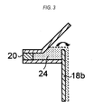
- FIG 3 shows a cylindrical weir 18b having a rounded inside top edge.
- the basic structure of this example of the water-film formation mechanism is the same as that in FIG 2 . This example can form a smooth flow of the water overflowing the weir 18b.
- FIG 4 is a modified example of FIG 2 , and shows a weir 18c having a top portion with a L-shaped cross section.
- This example of the water-film formation mechanism comprises annular water reservoir 24 and the weir 18c.
- the weir 18c forms part of the water reservoir 24.
- FIG 5 shows a cylindrical weir 18d having a top portion with a L-shaped cross section and having a rounded inside top edge.
- the basic structure of this example of the water-film formation mechanism is the same as that in FIG 4 .
- FIG 6 shows an example in which a cylindrical member 33 is provided radially inwardly of a cylindrical weir 18e and water flows down through a small gap between the weir 18e and the cylindrical member 33.
- This example of the water-film formation mechanism comprises annular water reservoir 24, the weir 18e, and the cylindrical member 33.
- the weir 18e forms part of the water reservoir 24.
- FIG 7A and FIG 7B show an example in which rectangular openings 20f are formed below a top portion of a cylindrical weir 18f such that water flows through the openings 20f to the inner surface of the cylindrical body 18.
- This example of the water-film formation mechanism comprises annular water reservoir 24, the weir 18f, and the rectangular openings 20f formed in the weir 18f.
- FIG 8A and FIG 8B show outlets 20g through which water flows out to form spiral flow on the inner circumferential surface of the cylindrical body 18.
- This example of the water-film formation mechanism comprises the plural outlets 20g formed in the inner surface of the cylindrical body 18. More specifically, the outlets 20g form the water flows in a horizontal direction along the inner circumferential surface of the cylindrical body 18.
- FIGS. 9A through 9C show outlets 20h through which water flows out to form spiral flow on the inner circumferential surface of the cylindrical body 18.
- This example of the water-film formation mechanism comprises annular water reservoir 24, and the vertically-elongated outlets 20h formed in the inner surface of the cylindrical body 18.
- Each of the outlets 20h has a rectangular shape whose one side is opened, so that the water flows out horizontally in the tangential direction to form the water film that covers the rectangular outlet 20h itself.
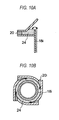
- FIG 10A and FIG 10B show an example in which water is supplied from a tangential direction into water reservoir 24 so as to form a swirling flow in the water reservoir 24 such that the water overflows the weir 18i to form spiral flow.
- This example of the water-film formation mechanism comprises the annular water reservoir 24, the weir 18i, and at least one supply port 20i for supplying the water from the tangential direction of the water reservoir 24 into the water reservoir 24.
- the weir 18i forms part of the water reservoir 24.
- a water level in the water reservoir 24 is uniformly increased throughout the circumferential direction thereof, and the water overflows the weir 18i uniformly onto the inner surface of the cylindrical body 18.
- One or more supply port 20i can be provided. Even if a single supply port 20i is provided, the swirling flow of the water can be formed in the water reservoir 24. Therefore, a uniform water film can be formed on the inner surface of the cylindrical body 18. According to this example, even if the cylindrical body 18 is inclined at a certain degree (for example, with a gradient such that height to length is 1 cm to 200 cm) from the horizontal direction due to installation conditions of the exhaust-gas treatment apparatus 10, a uniform water film can be formed stably.
- FIG 11 is a whole structural example of the combustion-type exhaust gas treatment apparatus 10.
- Fuel and oxygen are supplied via pipes 35 and 36 to a premixer 37, where the fuel and the oxygen are mixed with each other to form a premixed fuel.
- This premixed fuel is supplied to the combustion treatment section 11 via a pipe 38.
- Air which serves as an oxygen source for combusting (i.e., oxidizing) the exhaust gas, is supplied to the combustion treatment section 11 via a pipe 39.
- the combustion-type exhaust gas treatment apparatus 10 comprises a cooling section 21 for cooling the exhaust gas that has been subjected to the combustion treatment, and a circulation tank 25 for storing and circulating the water which was used to form the water film A on the inner surface of the cylindrical body 18.
- the cooling section 21 is located downstream of the cylindrical body 18.
- the cooling section 21 comprises a pipe 22 which couples a lower end portion of the cylindrical body 18 and the circulation tank 25 to each other, and a pipe 27 which branches off the pipe 22 to a washing section 31.
- the pipe 27, which branches off the pipe 22, is inclined upwardly and is coupled to a lower end portion of the washing section (washing chamber) 31 via a vertical pipe.
- a water-spraying mechanism 28 for forming a water film on an inner surface of the pipe 27 is provided near a connection portion between the pipe 27 and the vertical pipe.
- An inner surface of the pipe 22 is covered in its entirety with the water film which has flowed down from the cylindrical body 18, and the inner surface of the pipe 27 is covered in its entirety with the water film formed by the water-spraying mechanism 28. Because these water films serve as a heat-resisting material, temperatures of the pipes 22 and 27 can be kept at substantially ordinary temperature (not more than 50°C), regardless of a high temperature of the exhaust gas which has been subjected to the combustion treatment. Moreover, the water films can prevent damages from the corrosive gas to the pipes. Therefore, a low-priced stainless steel can be used for the pipes 22 and 27.
- FIGS. 12A , 12B through 16A , 16B show examples of the cooling-acceleration mechanism such as fin or baffle plate.
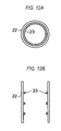
- FIG 12A and FIG 12B show ring-shaped fins 23 arranged on the inner surface of the pipe 22.
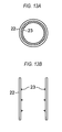
- FIG 13A and FIG 13B also show ring-shaped fins 23.
- the example shown in FIG 13A and FIG 13B is different from the example shown in FIG 12A and FIG 12B in that the fin 23 in FIG 12A and FIG 12B has a rectangular cross section and the fin 23 in FIG 13A and FIG 13B has a triangular cross section.
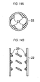
- FIG 14A and FIG 14B show short fins 23 inclined along the flowing direction of the exhaust gas in the pipe 22.
- FIG 15A and FIG 15B show semicircular baffle plates 23 provided on the inner surface of the pipe 22.
- Each of the semicircular baffle plates 23 is in such a shape as to fit a portion of the inner surface of the pipe 22.
- the baffle plates 23 are arranged at different vertical positions and different circumferential positions. The exhaust gas flows through the pipe 22 while contacting the inner surface of the pipe 22 and the baffle plates 23. In this manner, the cooling effect of the exhaust gas can be accelerated by the fins or baffle plates which are covered with the water film.
- FIG 16A and FIG 16B show a spiral fin 23 provided on the inner circumferential surface of the pipe 22.
- the washing section 31 of the combustion-type exhaust gas treatment apparatus 10 comprises filters 31a and water-spraying mechanisms 31b. After the combustion treatment, the exhaust gas is cooled by the cooling section 21, and then introduced into the washing section 31. This washing section 31 washes the exhaust gas with water so as to capture and remove by-products including the dust and the oxidizing gas produced by the combustion treatment of the exhaust gas. The dust is removed by the filters 31a, and goes down with water sprayed from the water-spraying mechanisms 31b. The dust with the water flows through the pipes 27 and 22 into the circulation tank 25, and is stored in the tank 25. In this manner, the exhaust gas is rendered harmless by the combustion treatment, cooled in the cooling section 21, and washed with water in the washing section 31. The treated exhaust gas flows through a pipe 32 and is then released into the atmosphere or other space.
- the circulation tank 25 has a weir 26 therein. After flowing down through the pipe 22, the water enters a chamber at a left side of the weir 26 as in the drawing. The water in the left chamber overflows the weir 26 into a chamber at a right side of the weir 26 as in the drawing. The water in the right chamber is sucked by a pump 30 and delivered to a heat exchanger 40 via a supply pipe 34. The heat exchanger 40 performs heat exchange between the water and cooling water so that the water has a suitable temperature. Thereafter, this water is reused as circulation water. The water, containing a large amount of dust, flows into the left chamber of the circulation tank 25. The dust is formed by particles, some of which have large diameters.
- the large particles are heavy, they sink to a bottom of the chamber.
- particles with very small diameters are lightweight, and thus overflow the weir 26 into the right chamber.
- the particles that were moved to the right chamber are mixed into the water that is to be used as the circulation water.
- the particles, mixed into the circulation water may not have an adverse effect in use of the circulation water, so long as the particles have a diameter of about 50 ⁇ m. Accordingly, it is preferable that the weir 26 have a height such that particles with a diameter of more than 50 ⁇ m cannot overflow the weir 26.
- the water is supplied as water W1 to the water-flow flange 20.
- the water W1 is used to form the water film A on the inner surface of the cylindrical body 18, and to form the water film on the inner circumferential surface of the pipe 22.
- the water is returned to the circulation tank 25.
- Part of the water, whose temperature has been adjusted in the heat exchanger 40 is supplied to the water-spraying mechanisms 31b of the washing sections 31, and is returned to the circulation tank 25.
- part of the water, whose temperature has been adjusted in the heat exchanger 40 is supplied to the water-spraying mechanism 28, which forms the water film on the inner circumferential surface of the pipe 22. Then, the water is returned to the circulation tank 25.
- the combustion-type exhaust gas treatment apparatus 10 has an advantage of requiring a very small amount of city water or industrial water for replenishment because most of the water used in operations of the apparatus 10 is the circulation water. Furthermore, because the water is reused as the circulation water, even if the water becomes a thin hydrofluoric acid after washing the exhaust gas, this acid is not expelled to the exterior of the apparatus 10.
- Part of the cooling water to be supplied to the heat exchanger 40 is supplied as cooling water W2 to a non-illustrated cooling-water passage provided in the combustion treatment section 11.
- This water W2 serves to cool the exhaust-gas treatment combustor 12.
- Part of the water delivered by the pump 30 is supplied as water W3 to the circulation tank 25 so that the water W3 flows into the circulation tank 25 from a side portion of the circulation tank 25.
- the water, which has flowed into the circulation tank 25, sweeps away the by-products deposited on the bottom of the circulation tank 25 toward the weir 26, thereby preventing clogging of a lower end opening of the pipe 22 with the by-products.
- the combustion-type exhaust gas treatment apparatus 10 comprises a temperature sensor 41 on the cylindrical body 18, and monitors an increase in temperature of the cylindrical body 18 with the temperature sensor 41. If the water break occurs on the inner surface of the cylindrical body 18, the heat resisting effect disappears at that portion. In such a case, the cylindrical body 18 is in direct contact with the high-temperature exhaust gas, which potentially causes damage to the inner surface of the cylindrical body 18. In order to detect such situations, the temperature sensor 41 is provided on the cylindrical body 18 so as to secure the safety.
- a leak sensor 42 is provided on a portion that serves as a saucer of the cylindrical body 18. If the cylindrical body 18 is damaged and a through-hole is formed, the leak sensor 42 can detect the presence of such a through-hole. In this manner, providing the leak sensor 42 can improve the safety.
Landscapes
- Engineering & Computer Science (AREA)
- Mechanical Engineering (AREA)
- General Engineering & Computer Science (AREA)
- Environmental & Geological Engineering (AREA)
- Chemical & Material Sciences (AREA)
- Combustion & Propulsion (AREA)
- Incineration Of Waste (AREA)
Abstract
Description
- The present invention relates to a combustion-type exhaust gas treatment apparatus for treating a harmful and combustible exhaust gas, which contains, for example, silane gas (SiH4) or halogen gas (NF3, ClF3, SF6, CHF3, C2F6, CF4, or the like), by combustion so as to render the exhaust gas harmless.
- A semiconductor fabrication apparatus discharges a gas including a harmful and combustible exhaust gas, e.g., silane gas (SiH4) or halogen gas (NF3, ClF3, SF6, CHF3, C2F6, CF4). Such an exhaust gas cannot be released as it is into the atmosphere. Thus, the exhaust gas is generally introduced to a treatment apparatus, where the exhaust gas is oxidized by combustion so as to be rendered harmless. A widely-used treatment process of this type is such that a combustion-supporting gas is used to form flames in a furnace in which the exhaust gas is combusted by the flames, as seen in
Japanese laid-open patent publication No. 11-218317 - A combustion-type exhaust gas treatment apparatus for use in a semiconductor industry and a liquid crystal industry potentially discharges a large amount of dust (mainly SiO2) and a large amount of an acid gas as by-products of combustion treatment of the exhaust gas. Consequently, regular maintenance operation is required so as to remove the dust from a treatment section, or an additional mechanism, such as a scraper, is required so as to regularly scrape away the dust attached to and deposited on an inner surface of a cylindrical body of a combustion treatment chamber.
- The dust attached and deposited is composed mainly of SiO2 (i.e., silicon dioxide). Other than SiO2, however, the dust may probably have toxic dust mixed therewith. The dust has various diameters ranging from 0.1 micrometers to several tens of micrometers. Moreover, the dust may exist as large blocks. Consequently, it is necessary to ensure operational safety of the dust-removal maintenance so as not to cause health damage from suction of the dust.
- In the case of providing the scraping mechanism, the number of components is increased. As a result, a manufacturing cost of products would be increased, and replacement of the scraping mechanism would be regularly required, thus increasing a running cost.
- Because a temperature of a combustion gas in the combustion treatment chamber is as high as about 1700°C, a heat-resisting material, such as alumina-base glass ceramic, is used for the cylindrical body that surrounds the combustion treatment chamber. However, the temperature of the combustion treatment chamber is high, and if a fluorine or chlorine gas exists, the inner surface of the cylindrical body would be corroded and wasted. Therefore, it is necessary to regularly replace the cylindrical body. Such replacement of the high-priced cylindrical body incurs a cost and requires a time-consuming maintenance.
- The present invention has been made in view of the above drawbacks. It is therefore an object of the present invention to provide a combustion-type exhaust gas treatment apparatus which can use a low-priced material for a body that surrounds a combustion treatment chamber, can prevent attachment of dust to an inner surface of the combustion treatment chamber, can prevent damage from a corrosive gas to the inner surface of the combustion treatment chamber, and can reduce a time-consuming maintenance and a maintenance cost.
- A combustion-type exhaust gas treatment apparatus according to the present invention includes a combustion treatment section for performing combustion treatment on an exhaust gas, a cooling section for cooling the exhaust gas which has been treated in the combustion treatment section, and a washing section for washing the exhaust gas with water so as to remove by-products produced by the combustion treatment. The combustion treatment section includes an exhaust-gas treatment combustor, a body made from metal and having a roughened inner surface, and a water-film formation mechanism adapted to form a water film on the inner surface of the body. The combustion treatment of the exhaust gas is performed in the body.
- As described above, the present invention provides the combustion-type exhaust gas treatment apparatus including the metal body with the roughened inner surface, so that the exhaust gas is treated by combustion in the body. The water film, which is formed on the inner surface of the body, provides a water-resisting structure. Therefore, a low-priced material, such as stainless steel, can be used to form the body. Moreover, the water film, which is formed on the inner surface of the body, can wash away the dust to thereby prevent the dust from adhering to the inner surface of the body. Furthermore, the water film can wash away the corrosive gas, and therefore the inner surface of the body is not damaged. As a result, a low-priced material, such as stainless steel, can be used to form the body, thus lowering the manufacturing cost of the body itself. In addition, the time-consuming maintenance and the maintenance cost can be reduced.
-
-
FIG 1 is a cross-sectional view showing a combustion treatment section according to an embodiment of the present invention; -
FIG 2 is a cross-sectional view showing an example of a water-film formation mechanism; -
FIG 3 is a cross-sectional view showing a modified example of the water-film formation mechanism; -
FIG 4 is a cross-sectional view showing another modified example of the water-film formation mechanism; -
FIG 5 is a cross-sectional view showing still another modified example of the water-film formation mechanism; -
FIG 6 is a cross-sectional view showing still another modified example of the water-film formation mechanism; -
FIG 7A is a cross-sectional view showing still another modified example of the water-film formation mechanism; -
FIG 7B is a front view of the water-film formation mechanism shown inFIG 7A ; -
FIG 8A is a plan view showing still another modified example of the water-film formation mechanism; -
FIG 8B is a cross-sectional view of the water-film formation mechanism shown inFIG 8A ; -
FIG 9A is a plan view showing still another modified example of the water-film formation mechanism; -
FIG 9B is a cross-sectional view of the water-film formation mechanism shown inFIG 9A ; -
FIG 9C is a front view of the water-film formation mechanism shown inFIG 9A ; -
FIG 10A is a cross-sectional view showing still another modified example of the water-film formation mechanism; -
FIG 10B is a plan view of the water-film formation mechanism shown inFIG 10A ; -
FIG 11 is a block diagram showing a combustion-type exhaust gas treatment apparatus according to an embodiment of the present invention; -
FIG 12A is a plan view showing an example of a cooling-acceleration mechanism; -
FIG 12B is a cross-sectional view of the mechanism shown inFIG 12A ; -
FIG 13A is a plan view showing another example of the cooling-acceleration mechanism; -
FIG 13B is a cross-sectional view of the mechanism shown inFIG 13A ; -
FIG 14A is a plan view showing another example of the cooling-acceleration mechanism; -
FIG 14B is a cross-sectional view of the mechanism shown inFIG 14A ; -
FIG 15A is a plan view showing another example of the cooling-acceleration mechanism; -
FIG 15B is a cross-sectional view of the mechanism shown inFIG 15A ; -
FIG 16A is a plan view showing another example of the cooling-acceleration mechanism; and -
FIG 16B is a cross-sectional view of the mechanism shown inFIG 16A . - Embodiments of the present invention will be described below with reference to the drawings. In the drawings, components or elements having the same function or structure are denoted by the same reference numerals.
-
FIG 1 is a cross-sectional view showing a combustion treatment section of a combustion-type exhaust gas treatment apparatus according to an embodiment of the present invention. Thecombustion treatment section 11 comprises an exhaust-gas treatment combustor 12. An exhaust gas is supplied throughnozzles 13, and is then mixed with swirling flows of air supplied throughair nozzles 14 and with a combustion-supporting gas supplied through combustion-supporting-gas nozzles 15. The mixture is combusted to thereby formflames 17. A combustion treatment chamber (flame holding chamber) 19, which is surrounded by acylindrical body 18, is provided downstream of theflames 17. Combustion and treatment of the exhaust gas progress in thiscombustion treatment chamber 19. A water-flow flange 20 is provided between the exhaust-gas treatment combustor 12 and thecylindrical body 18, so that water flows down along an inner surface of thecylindrical body 18, thereby forming a water film A on the inner surface of thecylindrical body 18. - In this embodiment, stainless steel is used to form the
cylindrical body 18. The inner surface of thiscylindrical body 18 comprises a roughened surface. Since the inner surface of thecylindrical body 18 is roughened, a wettability of the inner surface is improved, and thus a uniform water film can be formed on the inner surface in its entirety. If a stainless steel, which is a hydrophobic material, has a mirror-finished inner surface, water droplets are likely to be formed thereon. Accordingly, it is difficult to form a uniform water film on the inner surface in its entirety. Because the inner surface of thecylindrical body 18 is roughened in its entirety, the stable water film can be formed on the inner surface in its entirety of thecylindrical body 18 with no water break. - The roughened surface can be formed by blasting, which is a method of forming a rough surface with a desired roughness by ejecting abrasives (e.g., sands or glass beads) at high speed to a surface using a compressed air or centrifugal force. The roughened surface may be formed by machining, such as cutting (broaching) which uses multiple blades or a spline method which scrapes a workpiece by a combination of a vertically-linear motion of a tool and a feed motion of the workpiece. Alternatively, the roughened surface may be formed by surface treatment, such as pickling or hydrophilic coating. Pickling is conducted by immersing a workpiece in a chemical liquid (e.g., nitric acid, hydrofluoric acid, hydrochloric acid, sulfuric acid), removing the workpiece from the chemical liquid, washing the workpiece with water, and drying the workpiece. Hydrophilic coating is conducted by coating an inner surface with a hydrophilic film, such as glass fiber, silicon polymer, or Teflon (registered trademark).
- A preferable temperature for decomposition of the exhaust gas is at least 1700°C. Therefore, a temperature in the
combustion treatment chamber 19 is kept at around 1700°C. An amount of water supplied from the water-flow flange 20 is adjusted such that the water film A has a thickness of at least 2 mm. The water film A with a thickness of at least 2 mm can provide a heat-resisting structure, whereby the temperature of thecylindrical body 18 is kept at substantially an ordinary temperature (not more than 50°C). Therefore, a low-priced material, such as stainless steel, can be used for thecylindrical body 18, instead of the high-priced alumina-base glass ceramic. When the temperature of the water in the water-flow flange 20 is 30°C, the temperature of the water at an outlet of thecylindrical body 18 can be at several tens of degrees or less. - When dust, which has been produced in the
combustion treatment chamber 19, approaches the inner surface of thecylindrical body 18, the water film A washes away the dust, thereby preventing the dust from adhering to the inner surface of thecylindrical body 18. Similarly, when molecules of a corrosive gas approach the inner surface of thecylindrical body 18, the water film A washes away the molecules of the corrosive gas. For example, when a fluorine by-product is produced in the combustion treatment, such a fluorine by-product becomes a thin hydrofluoric acid, which does not cause damage to the inner surface of thecylindrical body 18. Therefore, even if a low-priced material, such as stainless steel, is used for thecylindrical body 18, the dust does not adhere to the inner surface, and the inner surface is not corroded by the oxidizing gas. As a result, the time-consuming maintenance and the maintenance cost can be greatly reduced. - In
FIG 1 , the inner surface of thecylindrical body 18 has a cylindrical shape with an inside diameter being constant from an upper end to a lower end of thecylindrical body 18. Alternatively, the inner surface of thecylindrical body 18 may have a conical shape with an inside diameter being gradually reduced in size from an upper end to a lower end of thecylindrical body 18. The cylindrical shape has advantages of eliminating a welded portion from the combustion treatment chamber to thereby avoid the water break, and simplifying the production of the cylindrical body to thereby reduce the manufacturing cost. The conical shape has an advantage in that the water film is easily formed because of its tapered shape. On the other hand, the conical shape requires a technical skill of welding so as not to cause the water break, and as a result, the manufacturing cost would be increased. -
FIGS. 2 through 10 show examples of mechanism for forming the water film on the inner surface of the cylindrical body. -
FIG 2 is a cross-sectional view showing an example of the water-flow flange (water-film formation mechanism) 20. This example of the water-film formation mechanism 20 comprises anannular water reservoir 24 and aweir 18a. Theweir 18a forms part of thewater reservoir 24. Theweir 18a has a top portion with a uniform height. Therefore, a uniform water film with a uniform thickness can be formed on the inner surface of thecylindrical body 18.FIG 3 shows acylindrical weir 18b having a rounded inside top edge. The basic structure of this example of the water-film formation mechanism is the same as that inFIG 2 . This example can form a smooth flow of the water overflowing theweir 18b. -
FIG 4 is a modified example ofFIG 2 , and shows aweir 18c having a top portion with a L-shaped cross section. This example of the water-film formation mechanism comprisesannular water reservoir 24 and theweir 18c. Theweir 18c forms part of thewater reservoir 24.FIG 5 shows acylindrical weir 18d having a top portion with a L-shaped cross section and having a rounded inside top edge. The basic structure of this example of the water-film formation mechanism is the same as that inFIG 4 .FIG 6 shows an example in which acylindrical member 33 is provided radially inwardly of acylindrical weir 18e and water flows down through a small gap between theweir 18e and thecylindrical member 33. This example of the water-film formation mechanism comprisesannular water reservoir 24, theweir 18e, and thecylindrical member 33. Theweir 18e forms part of thewater reservoir 24. -
FIG 7A and FIG 7B show an example in whichrectangular openings 20f are formed below a top portion of acylindrical weir 18f such that water flows through theopenings 20f to the inner surface of thecylindrical body 18. This example of the water-film formation mechanism comprisesannular water reservoir 24, theweir 18f, and therectangular openings 20f formed in theweir 18f.FIG 8A and FIG 8B show outlets 20g through which water flows out to form spiral flow on the inner circumferential surface of thecylindrical body 18. This example of the water-film formation mechanism comprises theplural outlets 20g formed in the inner surface of thecylindrical body 18. More specifically, theoutlets 20g form the water flows in a horizontal direction along the inner circumferential surface of thecylindrical body 18. Because theplural outlets 20g are provided, a water film with a uniform thickness is formed on the inner circumferential surface of thecylindrical body 18.FIGS. 9A through 9C show outlets 20h through which water flows out to form spiral flow on the inner circumferential surface of thecylindrical body 18. This example of the water-film formation mechanism comprisesannular water reservoir 24, and the vertically-elongatedoutlets 20h formed in the inner surface of thecylindrical body 18. Each of theoutlets 20h has a rectangular shape whose one side is opened, so that the water flows out horizontally in the tangential direction to form the water film that covers therectangular outlet 20h itself. -
FIG 10A and FIG 10B show an example in which water is supplied from a tangential direction intowater reservoir 24 so as to form a swirling flow in thewater reservoir 24 such that the water overflows theweir 18i to form spiral flow. This example of the water-film formation mechanism comprises theannular water reservoir 24, theweir 18i, and at least onesupply port 20i for supplying the water from the tangential direction of thewater reservoir 24 into thewater reservoir 24. Theweir 18i forms part of thewater reservoir 24. When the water is supplied to thewater reservoir 24 through thesupply port 20i, the swirling flow of the water is formed in thewater reservoir 24. As a result, a water level in thewater reservoir 24 is uniformly increased throughout the circumferential direction thereof, and the water overflows theweir 18i uniformly onto the inner surface of thecylindrical body 18. One ormore supply port 20i can be provided. Even if asingle supply port 20i is provided, the swirling flow of the water can be formed in thewater reservoir 24. Therefore, a uniform water film can be formed on the inner surface of thecylindrical body 18. According to this example, even if thecylindrical body 18 is inclined at a certain degree (for example, with a gradient such that height to length is 1 cm to 200 cm) from the horizontal direction due to installation conditions of the exhaust-gas treatment apparatus 10, a uniform water film can be formed stably. -
FIG 11 is a whole structural example of the combustion-type exhaustgas treatment apparatus 10. Fuel and oxygen are supplied viapipes premixer 37, where the fuel and the oxygen are mixed with each other to form a premixed fuel. This premixed fuel is supplied to thecombustion treatment section 11 via apipe 38. Air, which serves as an oxygen source for combusting (i.e., oxidizing) the exhaust gas, is supplied to thecombustion treatment section 11 via apipe 39. - The combustion-type exhaust
gas treatment apparatus 10 comprises acooling section 21 for cooling the exhaust gas that has been subjected to the combustion treatment, and acirculation tank 25 for storing and circulating the water which was used to form the water film A on the inner surface of thecylindrical body 18. Thecooling section 21 is located downstream of thecylindrical body 18. Thecooling section 21 comprises apipe 22 which couples a lower end portion of thecylindrical body 18 and thecirculation tank 25 to each other, and apipe 27 which branches off thepipe 22 to awashing section 31. Thepipe 27, which branches off thepipe 22, is inclined upwardly and is coupled to a lower end portion of the washing section (washing chamber) 31 via a vertical pipe. A water-sprayingmechanism 28 for forming a water film on an inner surface of thepipe 27 is provided near a connection portion between thepipe 27 and the vertical pipe. - An inner surface of the
pipe 22 is covered in its entirety with the water film which has flowed down from thecylindrical body 18, and the inner surface of thepipe 27 is covered in its entirety with the water film formed by the water-sprayingmechanism 28. Because these water films serve as a heat-resisting material, temperatures of thepipes pipes - It is preferable to provide a cooling-acceleration mechanism, such as fin or baffle plate, on the inner surface of the
pipe 22 or thepipe 27.FIGS. 12A ,12B through 16A ,16B show examples of the cooling-acceleration mechanism such as fin or baffle plate.FIG 12A and FIG 12B show ring-shapedfins 23 arranged on the inner surface of thepipe 22.FIG 13A and FIG 13B also show ring-shapedfins 23. The example shown inFIG 13A and FIG 13B is different from the example shown inFIG 12A and FIG 12B in that thefin 23 inFIG 12A and FIG 12B has a rectangular cross section and thefin 23 inFIG 13A and FIG 13B has a triangular cross section.FIG 14A and FIG 14B showshort fins 23 inclined along the flowing direction of the exhaust gas in thepipe 22.FIG 15A and FIG 15B showsemicircular baffle plates 23 provided on the inner surface of thepipe 22. Each of thesemicircular baffle plates 23 is in such a shape as to fit a portion of the inner surface of thepipe 22. In thepipe 22, thebaffle plates 23 are arranged at different vertical positions and different circumferential positions. The exhaust gas flows through thepipe 22 while contacting the inner surface of thepipe 22 and thebaffle plates 23. In this manner, the cooling effect of the exhaust gas can be accelerated by the fins or baffle plates which are covered with the water film.FIG 16A and FIG 16B show aspiral fin 23 provided on the inner circumferential surface of thepipe 22. - The
washing section 31 of the combustion-type exhaustgas treatment apparatus 10 comprisesfilters 31a and water-sprayingmechanisms 31b. After the combustion treatment, the exhaust gas is cooled by thecooling section 21, and then introduced into thewashing section 31. Thiswashing section 31 washes the exhaust gas with water so as to capture and remove by-products including the dust and the oxidizing gas produced by the combustion treatment of the exhaust gas. The dust is removed by thefilters 31a, and goes down with water sprayed from the water-sprayingmechanisms 31b. The dust with the water flows through thepipes circulation tank 25, and is stored in thetank 25. In this manner, the exhaust gas is rendered harmless by the combustion treatment, cooled in thecooling section 21, and washed with water in thewashing section 31. The treated exhaust gas flows through apipe 32 and is then released into the atmosphere or other space. - The
circulation tank 25 has aweir 26 therein. After flowing down through thepipe 22, the water enters a chamber at a left side of theweir 26 as in the drawing. The water in the left chamber overflows theweir 26 into a chamber at a right side of theweir 26 as in the drawing. The water in the right chamber is sucked by apump 30 and delivered to aheat exchanger 40 via asupply pipe 34. Theheat exchanger 40 performs heat exchange between the water and cooling water so that the water has a suitable temperature. Thereafter, this water is reused as circulation water. The water, containing a large amount of dust, flows into the left chamber of thecirculation tank 25. The dust is formed by particles, some of which have large diameters. Since the large particles are heavy, they sink to a bottom of the chamber. On the other hand, particles with very small diameters are lightweight, and thus overflow theweir 26 into the right chamber. The particles that were moved to the right chamber are mixed into the water that is to be used as the circulation water. The particles, mixed into the circulation water, may not have an adverse effect in use of the circulation water, so long as the particles have a diameter of about 50 µm. Accordingly, it is preferable that theweir 26 have a height such that particles with a diameter of more than 50 µm cannot overflow theweir 26. - After the temperature is adjusted in the
heat exchanger 40, the water is supplied as water W1 to the water-flow flange 20. The water W1 is used to form the water film A on the inner surface of thecylindrical body 18, and to form the water film on the inner circumferential surface of thepipe 22. Then, the water is returned to thecirculation tank 25. Part of the water, whose temperature has been adjusted in theheat exchanger 40, is supplied to the water-sprayingmechanisms 31b of thewashing sections 31, and is returned to thecirculation tank 25. In addition, part of the water, whose temperature has been adjusted in theheat exchanger 40, is supplied to the water-sprayingmechanism 28, which forms the water film on the inner circumferential surface of thepipe 22. Then, the water is returned to thecirculation tank 25. In this manner, the water circulates. Therefore, the combustion-type exhaustgas treatment apparatus 10 has an advantage of requiring a very small amount of city water or industrial water for replenishment because most of the water used in operations of theapparatus 10 is the circulation water. Furthermore, because the water is reused as the circulation water, even if the water becomes a thin hydrofluoric acid after washing the exhaust gas, this acid is not expelled to the exterior of theapparatus 10. - Part of the cooling water to be supplied to the
heat exchanger 40 is supplied as cooling water W2 to a non-illustrated cooling-water passage provided in thecombustion treatment section 11. This water W2 serves to cool the exhaust-gas treatment combustor 12. Part of the water delivered by thepump 30 is supplied as water W3 to thecirculation tank 25 so that the water W3 flows into thecirculation tank 25 from a side portion of thecirculation tank 25. The water, which has flowed into thecirculation tank 25, sweeps away the by-products deposited on the bottom of thecirculation tank 25 toward theweir 26, thereby preventing clogging of a lower end opening of thepipe 22 with the by-products. - The combustion-type exhaust
gas treatment apparatus 10 comprises atemperature sensor 41 on thecylindrical body 18, and monitors an increase in temperature of thecylindrical body 18 with thetemperature sensor 41. If the water break occurs on the inner surface of thecylindrical body 18, the heat resisting effect disappears at that portion. In such a case, thecylindrical body 18 is in direct contact with the high-temperature exhaust gas, which potentially causes damage to the inner surface of thecylindrical body 18. In order to detect such situations, thetemperature sensor 41 is provided on thecylindrical body 18 so as to secure the safety. - A
leak sensor 42 is provided on a portion that serves as a saucer of thecylindrical body 18. If thecylindrical body 18 is damaged and a through-hole is formed, theleak sensor 42 can detect the presence of such a through-hole. In this manner, providing theleak sensor 42 can improve the safety. - Although certain preferred embodiments of the present invention have been described, it should be understood that the present invention is not limited to the embodiments described above, and various changes and modifications may be made without departing from the scope of the present invention.
Claims (12)
- A combustion-type exhaust gas treatment apparatus, comprising:a combustion treatment section for performing combustion treatment on an exhaust gas;a cooling section for cooling the exhaust gas which has been treated in said combustion treatment section; anda washing section for washing the exhaust gas with water so as to remove by-products produced by the combustion treatment,wherein said combustion treatment section includes:an exhaust-gas treatment combustor;a body made from metal and having a roughened inner surface, the combustion treatment of the exhaust gas being performed in said body; anda water-film formation mechanism adapted to form a water film on said inner surface of said body.
- The combustion-type exhaust gas treatment apparatus according to claim 1, wherein said inner surface of said body has a cylindrical shape with an inside diameter being constant from an upper end to a lower end of said body.
- The combustion-type exhaust gas treatment apparatus according to claim 1, wherein said inner surface of said body has a conical shape with an inside diameter being gradually reduced in size from an upper end to a lower end of the body.
- The combustion-type exhaust gas treatment apparatus according to claim 1, further comprising:a circulation tank provided downstream of said body, said circulation tank being coupled to said cooling section.
- The combustion-type exhaust gas treatment apparatus according to claim 4, wherein said circulation tank has a weir therein which prevents circulation of the by-products having a predetermined size.
- The combustion-type exhaust gas treatment apparatus according to claim 4, wherein said cooling section comprises:a first pipe configured to couple a lower end of said body and said circulation tank to each other;a second pipe branching off said first pipe to said washing section; andmechanisms adapted to form water films on inner surfaces of said first pipe and said second pipe.
- The combustion-type exhaust gas treatment apparatus according to claim 6, wherein:said second pipe is inclined upwardly from a portion where said second pipe branches off said first pipe; anda water-spraying mechanism is provided for spraying water toward said inner surface of said second pipe.
- The combustion-type exhaust gas treatment apparatus according to claim 6, further comprising:a fin or baffle plate provided on said inner surface of said first pipe or said second pipe.
- The combustion-type exhaust gas treatment apparatus according to claim 4, further comprising:a supply pipe and a pump for supplying water stored in said circulation tank to said water-film formation mechanism, said washing section, and said cooling section; anda heat exchanger coupled to said supply pipe.
- The combustion-type exhaust gas treatment apparatus according to claim 9, wherein the water, which has been supplied to said water-film formation mechanism and said washing section, is returned to said circulation tank via said cooling section.
- The combustion-type exhaust gas treatment apparatus according to claim 1, further comprising:a temperature sensor provided on said body, said temperature sensor being for detecting an increase in temperature of said body.
- The combustion-type exhaust gas treatment apparatus according to claim 1, further comprising:a leak sensor for detecting leakage of the water from said body.
Applications Claiming Priority (2)
| Application Number | Priority Date | Filing Date | Title |
|---|---|---|---|
| JP2006328248 | 2006-12-05 | ||
| JP2007296395A JP4937886B2 (en) | 2006-12-05 | 2007-11-15 | Combustion exhaust gas treatment equipment |
Publications (3)
| Publication Number | Publication Date |
|---|---|
| EP1933088A2 true EP1933088A2 (en) | 2008-06-18 |
| EP1933088A3 EP1933088A3 (en) | 2013-07-17 |
| EP1933088B1 EP1933088B1 (en) | 2015-08-26 |
Family
ID=39093006
Family Applications (1)
| Application Number | Title | Priority Date | Filing Date |
|---|---|---|---|
| EP07023594.0A Active EP1933088B1 (en) | 2006-12-05 | 2007-12-05 | Combustion-type exhaust gas treatment apparatus with film cooling |
Country Status (2)
| Country | Link |
|---|---|
| US (1) | US8591819B2 (en) |
| EP (1) | EP1933088B1 (en) |
Cited By (2)
| Publication number | Priority date | Publication date | Assignee | Title |
|---|---|---|---|---|
| EP3270058A4 (en) * | 2015-03-12 | 2018-11-21 | Ebara Corporation | Exhaust-gas treatment apparatus |
| EP3533509A1 (en) * | 2018-02-26 | 2019-09-04 | Ebara Corporation | Wet abatement system |
Families Citing this family (17)
| Publication number | Priority date | Publication date | Assignee | Title |
|---|---|---|---|---|
| DE102004001975A1 (en) * | 2004-01-13 | 2005-10-06 | Basf Ag | Process for the preparation of membranes |
| JP6196481B2 (en) * | 2013-06-24 | 2017-09-13 | 株式会社荏原製作所 | Exhaust gas treatment equipment |
| JP6895342B2 (en) | 2016-08-19 | 2021-06-30 | 株式会社荏原製作所 | Burner head for exhaust gas treatment equipment and its manufacturing method, and combustion chamber for exhaust gas treatment equipment, its manufacturing method and maintenance method |
| CN111306559A (en) * | 2017-07-07 | 2020-06-19 | 鉴锋国际股份有限公司 | Device and system for controlling decomposition and oxidation of gaseous pollutants |
| TWI754084B (en) * | 2017-08-03 | 2022-02-01 | 日商荏原製作所股份有限公司 | Exhaust gas treatment apparatus |
| WO2020185154A1 (en) * | 2019-03-12 | 2020-09-17 | Valmet Ab | System for recovering heat from flue gas, control arrangement for use in such a system and a method performed by such a control arrangement |
| JP7195439B2 (en) * | 2019-11-21 | 2022-12-23 | エコシス ピーティーイー リミテッド | Gas pollutant treatment equipment |
| CN110898621B (en) * | 2019-12-06 | 2022-05-17 | 东莞励国照明有限公司 | Oily air purification device and purification method thereof |
| CN111603870A (en) * | 2020-04-27 | 2020-09-01 | 陈艳梅 | Concrete processing apparatus is used in highway bridge construction |
| CN113803731B (en) * | 2021-10-12 | 2023-10-03 | 上海市计量测试技术研究院 | A high-efficiency regenerative catalytic combustion device for industrial organic waste gas |
| CN114788980B (en) * | 2022-05-18 | 2023-11-21 | 四川铸创安全科技有限公司 | Waste gas treatment equipment for chemical industry safety environmental protection |
| CN114923193B (en) * | 2022-06-07 | 2023-03-17 | 上海协微环境科技有限公司 | A Harmful Gas Combustion Reactor |
| US12577673B2 (en) | 2022-07-18 | 2026-03-17 | Applied Materials, Inc. | In-situ EPI growth rate control of crystal thickness using parametric resonance sensing |
| CN115254424B (en) * | 2022-07-28 | 2023-05-16 | 上海协微环境科技有限公司 | Tail gas treatment system with high-efficiency dust removal function |
| CN116717640B (en) * | 2023-05-29 | 2023-12-08 | 上海协微环境科技有限公司 | A flange component and exhaust gas treatment system that prevents vapor backflow |
| CN117065525B (en) * | 2023-10-11 | 2023-12-29 | 山西紫罗蓝新材料科技有限公司 | Falling film absorption tower |
| CN118059623B (en) * | 2024-04-19 | 2024-07-05 | 浙江奔乐生物科技股份有限公司 | Water film dust removal equipment |
Citations (1)
| Publication number | Priority date | Publication date | Assignee | Title |
|---|---|---|---|---|
| JPH11218317A (en) | 1997-11-21 | 1999-08-10 | Ebara Corp | Waste gas treating combustion device |
Family Cites Families (12)
| Publication number | Priority date | Publication date | Assignee | Title |
|---|---|---|---|---|
| US5123836A (en) * | 1988-07-29 | 1992-06-23 | Chiyoda Corporation | Method for the combustion treatment of toxic gas-containing waste gas |
| DE4320044A1 (en) | 1993-06-17 | 1994-12-22 | Das Duennschicht Anlagen Sys | Process and device for cleaning exhaust gases |
| US5591415A (en) * | 1994-01-27 | 1997-01-07 | Rpc Waste Management Services, Inc. | Reactor for supercritical water oxidation of waste |
| US5510093A (en) * | 1994-07-25 | 1996-04-23 | Alzeta Corporation | Combustive destruction of halogenated compounds |
| US6322756B1 (en) * | 1996-12-31 | 2001-11-27 | Advanced Technology And Materials, Inc. | Effluent gas stream treatment system having utility for oxidation treatment of semiconductor manufacturing effluent gases |
| US5955037A (en) * | 1996-12-31 | 1999-09-21 | Atmi Ecosys Corporation | Effluent gas stream treatment system having utility for oxidation treatment of semiconductor manufacturing effluent gases |
| US5833888A (en) * | 1996-12-31 | 1998-11-10 | Atmi Ecosys Corporation | Weeping weir gas/liquid interface structure |
| TW550112B (en) * | 1997-11-14 | 2003-09-01 | Hitachi Ltd | Method for processing perfluorocarbon, and apparatus therefor |
| DE10342692B4 (en) | 2003-09-09 | 2006-01-12 | DAS-Dünnschicht Anlagen Systeme GmbH Dresden | Device for the thermal treatment of pollutants containing process gases |
| US7569193B2 (en) * | 2003-12-19 | 2009-08-04 | Applied Materials, Inc. | Apparatus and method for controlled combustion of gaseous pollutants |
| DE102004047440B4 (en) | 2004-09-28 | 2007-11-08 | Centrotherm Clean Solutions Gmbh & Co.Kg | Arrangement for the purification of toxic gases from production processes |
| US7736599B2 (en) * | 2004-11-12 | 2010-06-15 | Applied Materials, Inc. | Reactor design to reduce particle deposition during process abatement |
-
2007
- 2007-12-04 US US11/987,764 patent/US8591819B2/en active Active
- 2007-12-05 EP EP07023594.0A patent/EP1933088B1/en active Active
Patent Citations (1)
| Publication number | Priority date | Publication date | Assignee | Title |
|---|---|---|---|---|
| JPH11218317A (en) | 1997-11-21 | 1999-08-10 | Ebara Corp | Waste gas treating combustion device |
Cited By (4)
| Publication number | Priority date | Publication date | Assignee | Title |
|---|---|---|---|---|
| EP3270058A4 (en) * | 2015-03-12 | 2018-11-21 | Ebara Corporation | Exhaust-gas treatment apparatus |
| US10215407B2 (en) | 2015-03-12 | 2019-02-26 | Ebara Corporation | Exhaust gas treatment apparatus |
| EP3533509A1 (en) * | 2018-02-26 | 2019-09-04 | Ebara Corporation | Wet abatement system |
| US11400406B2 (en) | 2018-02-26 | 2022-08-02 | Ebara Corporation | Wet abatement system |
Also Published As
| Publication number | Publication date |
|---|---|
| US8591819B2 (en) | 2013-11-26 |
| EP1933088B1 (en) | 2015-08-26 |
| EP1933088A3 (en) | 2013-07-17 |
| US20080131334A1 (en) | 2008-06-05 |
Similar Documents
| Publication | Publication Date | Title |
|---|---|---|
| EP1933088B1 (en) | Combustion-type exhaust gas treatment apparatus with film cooling | |
| KR101375202B1 (en) | Combustion-type exhaust gas treatment apparatus | |
| TWI680792B (en) | Exhaust gas treating device | |
| US6969250B1 (en) | Exhaust gas treating device | |
| US8246732B2 (en) | Exhaust gas cleaning apparatus | |
| US7985379B2 (en) | Reactor design to reduce particle deposition during process abatement | |
| JPWO2000032990A1 (en) | Exhaust gas treatment equipment | |
| US10920981B2 (en) | Burner head for exhaust gas processing apparatus, manufacturing method of the same, combustion chamber for exhaust gas processing apparatus, and manufacturing method and maintenance method of the same | |
| JP4084338B2 (en) | Heat treatment equipment for process exhaust gas containing pollutants | |
| KR20030007560A (en) | Treatment system for removing hazardous substances from a semiconductor process waste gas stream | |
| EP3533509B1 (en) | Wet abatement system | |
| JP2006255573A (en) | Exhaust gas cleaning cooling tower | |
| JP6659471B2 (en) | Exhaust gas treatment equipment | |
| RU2635626C1 (en) | Method for wet gas purification and device for its implementation | |
| KR102524186B1 (en) | Exhaust gas treatment device and exhaust gas treatment method | |
| KR20230096964A (en) | Exhaust gas treatment equipment | |
| JP2013166146A (en) | Exhaust gas cleaning method | |
| TW202005703A (en) | Gas abatement apparatus | |
| KR101576212B1 (en) | Scrubber With Function for Pre Wet |
Legal Events
| Date | Code | Title | Description |
|---|---|---|---|
| PUAI | Public reference made under article 153(3) epc to a published international application that has entered the european phase |
Free format text: ORIGINAL CODE: 0009012 |
|
| AK | Designated contracting states |
Kind code of ref document: A2 Designated state(s): AT BE BG CH CY CZ DE DK EE ES FI FR GB GR HU IE IS IT LI LT LU LV MC MT NL PL PT RO SE SI SK TR |
|
| AX | Request for extension of the european patent |
Extension state: AL BA HR MK RS |
|
| PUAL | Search report despatched |
Free format text: ORIGINAL CODE: 0009013 |
|
| AK | Designated contracting states |
Kind code of ref document: A3 Designated state(s): AT BE BG CH CY CZ DE DK EE ES FI FR GB GR HU IE IS IT LI LT LU LV MC MT NL PL PT RO SE SI SK TR |
|
| AX | Request for extension of the european patent |
Extension state: AL BA HR MK RS |
|
| RIC1 | Information provided on ipc code assigned before grant |
Ipc: F23G 7/06 20060101ALI20130610BHEP Ipc: F23G 5/24 20060101AFI20130610BHEP Ipc: F23M 5/00 20060101ALI20130610BHEP |
|
| 17P | Request for examination filed |
Effective date: 20140116 |
|
| RBV | Designated contracting states (corrected) |
Designated state(s): AT BE BG CH CY CZ DE DK EE ES FI FR GB GR HU IE IS IT LI LT LU LV MC MT NL PL PT RO SE SI SK TR |
|
| AKX | Designation fees paid |
Designated state(s): AT CH DE FR GB IT LI |
|
| 17Q | First examination report despatched |
Effective date: 20140307 |
|
| GRAP | Despatch of communication of intention to grant a patent |
Free format text: ORIGINAL CODE: EPIDOSNIGR1 |
|
| INTG | Intention to grant announced |
Effective date: 20150306 |
|
| GRAS | Grant fee paid |
Free format text: ORIGINAL CODE: EPIDOSNIGR3 |
|
| GRAA | (expected) grant |
Free format text: ORIGINAL CODE: 0009210 |
|
| AK | Designated contracting states |
Kind code of ref document: B1 Designated state(s): AT CH DE FR GB IT LI |
|
| REG | Reference to a national code |
Ref country code: GB Ref legal event code: FG4D |
|
| REG | Reference to a national code |
Ref country code: CH Ref legal event code: EP |
|
| REG | Reference to a national code |
Ref country code: AT Ref legal event code: REF Ref document number: 745415 Country of ref document: AT Kind code of ref document: T Effective date: 20150915 |
|
| REG | Reference to a national code |
Ref country code: DE Ref legal event code: R096 Ref document number: 602007042749 Country of ref document: DE |
|
| REG | Reference to a national code |
Ref country code: CH Ref legal event code: NV Representative=s name: RIEDERER HASLER AND PARTNER PATENTANWAELTE AG, LI |
|
| REG | Reference to a national code |
Ref country code: FR Ref legal event code: PLFP Year of fee payment: 9 |
|
| REG | Reference to a national code |
Ref country code: DE Ref legal event code: R097 Ref document number: 602007042749 Country of ref document: DE |
|
| PLBE | No opposition filed within time limit |
Free format text: ORIGINAL CODE: 0009261 |
|
| STAA | Information on the status of an ep patent application or granted ep patent |
Free format text: STATUS: NO OPPOSITION FILED WITHIN TIME LIMIT |
|
| 26N | No opposition filed |
Effective date: 20160530 |
|
| REG | Reference to a national code |
Ref country code: FR Ref legal event code: PLFP Year of fee payment: 10 |
|
| REG | Reference to a national code |
Ref country code: FR Ref legal event code: PLFP Year of fee payment: 11 |
|
| REG | Reference to a national code |
Ref country code: AT Ref legal event code: UEP Ref document number: 745415 Country of ref document: AT Kind code of ref document: T Effective date: 20150826 |
|
| PGFP | Annual fee paid to national office [announced via postgrant information from national office to epo] |
Ref country code: CH Payment date: 20201215 Year of fee payment: 14 Ref country code: FR Payment date: 20201112 Year of fee payment: 14 Ref country code: IT Payment date: 20201110 Year of fee payment: 14 |
|
| REG | Reference to a national code |
Ref country code: CH Ref legal event code: PL |
|
| PG25 | Lapsed in a contracting state [announced via postgrant information from national office to epo] |
Ref country code: FR Free format text: LAPSE BECAUSE OF NON-PAYMENT OF DUE FEES Effective date: 20211231 |
|
| PG25 | Lapsed in a contracting state [announced via postgrant information from national office to epo] |
Ref country code: LI Free format text: LAPSE BECAUSE OF NON-PAYMENT OF DUE FEES Effective date: 20211231 Ref country code: CH Free format text: LAPSE BECAUSE OF NON-PAYMENT OF DUE FEES Effective date: 20211231 |
|
| PG25 | Lapsed in a contracting state [announced via postgrant information from national office to epo] |
Ref country code: IT Free format text: LAPSE BECAUSE OF NON-PAYMENT OF DUE FEES Effective date: 20211205 |
|
| P01 | Opt-out of the competence of the unified patent court (upc) registered |
Effective date: 20230517 |
|
| PGFP | Annual fee paid to national office [announced via postgrant information from national office to epo] |
Ref country code: DE Payment date: 20251028 Year of fee payment: 19 |
|
| PGFP | Annual fee paid to national office [announced via postgrant information from national office to epo] |
Ref country code: GB Payment date: 20251030 Year of fee payment: 19 |
|
| PGFP | Annual fee paid to national office [announced via postgrant information from national office to epo] |
Ref country code: AT Payment date: 20251126 Year of fee payment: 19 |