EP1933024A2 - O-ring retainer for a fuel injector in a fuel rail socket - Google Patents
O-ring retainer for a fuel injector in a fuel rail socket Download PDFInfo
- Publication number
- EP1933024A2 EP1933024A2 EP07121309A EP07121309A EP1933024A2 EP 1933024 A2 EP1933024 A2 EP 1933024A2 EP 07121309 A EP07121309 A EP 07121309A EP 07121309 A EP07121309 A EP 07121309A EP 1933024 A2 EP1933024 A2 EP 1933024A2
- Authority
- EP
- European Patent Office
- Prior art keywords
- ring
- fuel
- fuel tube
- arrangement
- retaining ring
- Prior art date
- Legal status (The legal status is an assumption and is not a legal conclusion. Google has not performed a legal analysis and makes no representation as to the accuracy of the status listed.)
- Withdrawn
Links
Images

Classifications
-
- F—MECHANICAL ENGINEERING; LIGHTING; HEATING; WEAPONS; BLASTING
- F02—COMBUSTION ENGINES; HOT-GAS OR COMBUSTION-PRODUCT ENGINE PLANTS
- F02M—SUPPLYING COMBUSTION ENGINES IN GENERAL WITH COMBUSTIBLE MIXTURES OR CONSTITUENTS THEREOF
- F02M55/00—Fuel-injection apparatus characterised by their fuel conduits or their venting means; Arrangements of conduits between fuel tank and pump F02M37/00
- F02M55/004—Joints; Sealings
- F02M55/005—Joints; Sealings for high pressure conduits, e.g. connected to pump outlet or to injector inlet
-
- F—MECHANICAL ENGINEERING; LIGHTING; HEATING; WEAPONS; BLASTING
- F16—ENGINEERING ELEMENTS AND UNITS; GENERAL MEASURES FOR PRODUCING AND MAINTAINING EFFECTIVE FUNCTIONING OF MACHINES OR INSTALLATIONS; THERMAL INSULATION IN GENERAL
- F16L—PIPES; JOINTS OR FITTINGS FOR PIPES; SUPPORTS FOR PIPES, CABLES OR PROTECTIVE TUBING; MEANS FOR THERMAL INSULATION IN GENERAL
- F16L21/00—Joints with sleeve or socket
- F16L21/02—Joints with sleeve or socket with elastic sealing rings between pipe and sleeve or between pipe and socket, e.g. with rolling or other prefabricated profiled rings
- F16L21/035—Joints with sleeve or socket with elastic sealing rings between pipe and sleeve or between pipe and socket, e.g. with rolling or other prefabricated profiled rings placed around the spigot end before connection
Definitions
- the present invention relates to fuel injectors for internal combustion engines; more particularly, to means for sealing the fuel tube of a fuel injector into a fuel rail socket; and most particularly, to an improved O-ring retainer arrangement wherein the end of the fuel tube is inhibited from damaging either the fuel rail socket surface or a sealing O-ring, and wherein the O-ring retainer has an improved retention force tolerance.
- fuel typically is provided to the individual cylinders by individual fuel injectors that draw fuel from a common fuel distributor, known in the art as a fuel rail.
- a fuel rail Each fuel injector is mated to the fuel rail via an injector socket.
- a typical injector socket has a cylindrical inner wall or bore that intersects the fuel rail wall to permit fuel to flow from the fuel rail into the socket.
- a fuel injector includes a cylindrical fuel tube for insertion into the socket and further includes one or more O-rings disposed on the fuel tube for sealing against fuel leakage between the fuel tube and the socket.
- the O-ring typically is retained on the fuel tube by a retainer mechanism attached to or formed from the outer end of the fuel tube.
- the retainer mechanism is typically formed prior to installation of the O-ring onto the fuel tube; thus, the O-ring must pass over the retainer mechanism to complete the assembly. Further, should the injector be serviced later and the O-ring replaced, the replacement O-ring must again be stretched over the retainer mechanism.
- the retainer is a stamped metal part swaged onto the fuel tube or a radially flared end of the fuel tube itself. Either arrangement typically leaves a rough metal edge on the retainer that can inflict damage on the O-ring during assembly, causing a fuel leak during subsequent use of the injector. Further, if the fuel injector is cocked slightly when entering into the socket, the metal retainer edge can inadvertently score the socket wall, which may cause a fuel leak during injector use. Smoothing of the metal retainer is an added manufacturing cost and cannot fully assure that such damages will not occur. Alternatively, the retainer may be overmolded onto the fuel tube with a softer plastic material to prevent scoring of the socket wall. However, this too adds to the manufacturing costs and raises durability issues as well.
- annular groove is formed in the outer wall of the fuel tube and a plastic retainer is either overmolded into the groove or is pressed thereinto.
- An overmolded or pressed retainer in the groove is subject to breakage due to torsional forces acting on the ring because the axial stress vectors are not directly opposed. Either of these forming and assembly process can add significantly to the manufacturing cost of an injector. What is needed in the art is an inexpensive, reliable O-ring retainer arrangement for retaining an O-ring on the fuel tube of a fuel injector wherein the arrangement cannot damage the bore of an injector socket and wherein the retainer has superior compressive shock resistance.
- the end of the fuel tube is radially flared to retain the ring on the tube, the radial extent of the flare being less than or equal to the outer radius of the ring such that the flare cannot come into contact with the bore of a fuel rail socket.
- the ring is formed such that compressive forces exerted on the ring are outside the fuel tube body and preferably are directly opposed, thus exerting no toroidal torque on the ring.
- the ring is free to move axially on the fuel tube surface.
- a stamped metal retaining ring 102 is swaged onto the outer (fuel entrance) end 104 of a fuel tube 106 of a fuel injector 107.
- An elastomeric O-ring 108 is installed by stretching over end 104 and past retaining ring 102.
- O-ring 108 seals against both the outer surface 110 of fuel tube 106 and the inner surface 112 of a socket 114 in a fuel supply rail 116.
- a significant hazard in arrangement 100 is a sharp edge 118 on retaining ring 102 which can easily damage O-ring 108 during installation thereof onto fuel tube 106.
- edge 118 may inadvertently be engaged with surface 112 during insertion of the fuel injector into the socket, thus damaging surface 112 such that the surface cannot be sealed in use by contact with O-ring 108.
- a second prior art arrangement 200 the outer end 204 of a fuel tube 206 is flared radially to provide a radial retaining flange 202 for O-ring 208.
- This arrangement suffers from the same problems as arrangement 100.
- a groove 320 having an arcuate cross-section is formed in the outer surface 310 of a fuel tube 306.
- a plastic retaining ring 302 is overmolded onto tube 306, filling groove 320 and extending radially from surface 310 to retain an O-ring on tube 306.
- a problem is created by extending retaining ring 302 both into groove 320 and radially from surface 310.
- the O-ring is urged against ring 302 on a vector 322 at a mean location 324 radially off-spaced from surface 310 of tube 306, whereas a resistance vector 326 acts at groove corner 328 on surface 310, thus creating a torque couple which may lead to failure of ring 302 or failure of the joint between ring 302 and fuel tube 306.
- a rectangular groove 420 is machined into outer tube surface 410 and a multi-part plastic ring 402 is pressed into groove 420.
- a torque couple is formed between first vector 422 and resistance vector 426, which act at differing radial distances and therefore are not directly opposed, resulting in eventual failure of ring 402 at groove corner 428.
- a fuel injector fuel tube 506 is flared radially outwards defining a radial flange 502, similar to prior art flange 202.
- an additional retaining ring 502a is provided on the outer surface 510 of tube 506.
- Ring 502a is formed of an overmolded, rigid plastic and extends radially beyond the end of flange 502, thus preventing flange 502 from engaging and damaging the wall of the fuel socket during insertion, as can occur in prior art arrangements 100,200.
- Ring 502a is formed preferably from nylon 6 which is 33% glass filled.
- Radial flange 502 is formed in the end of fuel tube 506 after retaining ring 502a is installed over the fuel tube.
- the inside diameter of retaining ring 502a is greater than the outer diameter of the fuel tube allowing the retaining ring to slide freely on the outer surface of the fuel tube.
- ring 502a includes a first bearing protuberance 530 centered at a first radial distance 532 from wall surface 510 for engaging flange 502, and includes a second bearing protuberance 534 centered at a second radial distance 536 from wall surface 510 for engaging an O-ring; wherein first radial distance 532 and second radial distance 536 are equal. Therefore, no couple is created between vectors 538,540, being directly opposed, and no torsional stress is exerted on ring 502a.
- a second embodiment 600 of an O-ring retainer arrangement in accordance with the invention is similar to embodiment 500 except that the inner surface 650 of retaining ring 602a is arcuate and the entire ring is disposed in a region 652 of reduced diameter of fuel tube 606 adjacent radial flange 602.
- the inside diameter of retaining ring 602a is selected so that the ring slides freely only in region 652.
- a third embodiment 700 of an O-ring retainer arrangement in accordance with the invention comprises a retaining ring 702a having a generally rectangular cross-sectional shape; preferably inner ring corner 703 is radiused or chamfered to prevent contact and force accumulation at this point.
- the entire ring 702a is formed outside the cylindrical extension of surface 710 of fuel tube 706, thus allowing the compressive forces on the ring, as discussed previously in respect of embodiment 500, to be opposed and therefore to create no toroidal stress on the retaining ring.
- the inner diameter of retaining ring 702a is greater than the outer diameter of the associated fuel tube, allowing the retaining ring to slide freely on the outer surface of the fuel tube.
- the improved O-ring retaining arrangements 500,600,700 disclosed herein are improvements over prior art arrangements 100,200,300,400 in immunity from damaging fuel socket walls, and immunity from damaging an O-ring during installation thereof onto the fuel tube.
Landscapes
- Engineering & Computer Science (AREA)
- General Engineering & Computer Science (AREA)
- Mechanical Engineering (AREA)
- Chemical & Material Sciences (AREA)
- Combustion & Propulsion (AREA)
- Fuel-Injection Apparatus (AREA)
Abstract
Description
- The present invention relates to fuel injectors for internal combustion engines; more particularly, to means for sealing the fuel tube of a fuel injector into a fuel rail socket; and most particularly, to an improved O-ring retainer arrangement wherein the end of the fuel tube is inhibited from damaging either the fuel rail socket surface or a sealing O-ring, and wherein the O-ring retainer has an improved retention force tolerance.
- In modern internal combustion engines, either gasoline (spark ignited) or diesel (compression ignited), fuel typically is provided to the individual cylinders by individual fuel injectors that draw fuel from a common fuel distributor, known in the art as a fuel rail. Each fuel injector is mated to the fuel rail via an injector socket.
- A typical injector socket has a cylindrical inner wall or bore that intersects the fuel rail wall to permit fuel to flow from the fuel rail into the socket. A fuel injector includes a cylindrical fuel tube for insertion into the socket and further includes one or more O-rings disposed on the fuel tube for sealing against fuel leakage between the fuel tube and the socket. The O-ring typically is retained on the fuel tube by a retainer mechanism attached to or formed from the outer end of the fuel tube. During manufacture of the fuel injector, the retainer mechanism is typically formed prior to installation of the O-ring onto the fuel tube; thus, the O-ring must pass over the retainer mechanism to complete the assembly. Further, should the injector be serviced later and the O-ring replaced, the replacement O-ring must again be stretched over the retainer mechanism.
- In some prior art arrangements, the retainer is a stamped metal part swaged onto the fuel tube or a radially flared end of the fuel tube itself. Either arrangement typically leaves a rough metal edge on the retainer that can inflict damage on the O-ring during assembly, causing a fuel leak during subsequent use of the injector. Further, if the fuel injector is cocked slightly when entering into the socket, the metal retainer edge can inadvertently score the socket wall, which may cause a fuel leak during injector use. Smoothing of the metal retainer is an added manufacturing cost and cannot fully assure that such damages will not occur. Alternatively, the retainer may be overmolded onto the fuel tube with a softer plastic material to prevent scoring of the socket wall. However, this too adds to the manufacturing costs and raises durability issues as well.
- In some other prior art arrangements, an annular groove is formed in the outer wall of the fuel tube and a plastic retainer is either overmolded into the groove or is pressed thereinto. An overmolded or pressed retainer in the groove is subject to breakage due to torsional forces acting on the ring because the axial stress vectors are not directly opposed. Either of these forming and assembly process can add significantly to the manufacturing cost of an injector.
What is needed in the art is an inexpensive, reliable O-ring retainer arrangement for retaining an O-ring on the fuel tube of a fuel injector wherein the arrangement cannot damage the bore of an injector socket and wherein the retainer has superior compressive shock resistance. - It is a principal object of the present invention to prevent damage to an O-ring during installation of the O-ring onto a fuel tube of a fuel injector.
- It is a further object of the present invention to prevent damage to a fuel injector socket during assembly of a fuel injector into the socket.
- It is a still further object of the present invention to prevent compressive strain of an O-ring retaining means during use.
- Briefly described, an improved O-ring retainer arrangement for retaining an O-ring on a fuel tube of a fuel injector comprises an overmolded hard plastic ring disposed on the cylindrical outer surface of the fuel tube. The end of the fuel tube is radially flared to retain the ring on the tube, the radial extent of the flare being less than or equal to the outer radius of the ring such that the flare cannot come into contact with the bore of a fuel rail socket. The ring is formed such that compressive forces exerted on the ring are outside the fuel tube body and preferably are directly opposed, thus exerting no toroidal torque on the ring. Preferably, the ring is free to move axially on the fuel tube surface.
- The present invention will now be described, by way of example, with reference to the accompanying drawings, in which:
-
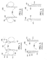
FIG. 1 is a schematic cross-sectional view of a first prior art arrangement for retaining an O-ring on a fuel injector fuel tube; -
FIG. 2 is a schematic cross-sectional view of a second prior art arrangement for retaining an O-ring on a fuel injector fuel tube; -
FIG. 3 is a schematic cross-sectional view of a third prior art arrangement for retaining an O-ring on a fuel injector fuel tube; -
FIG. 4 is a schematic cross-sectional view of a fourth prior art arrangement for retaining an O-ring on a fuel injector fuel tube; -
FIG. 5 is a schematic cross-sectional view of a first arrangement in accordance with the invention for retaining an O-ring on a fuel injector fuel tube; -
FIG. 6 is a schematic cross-sectional view of a second arrangement in accordance with the invention for retaining an O-ring on a fuel injector fuel tube; and -
FIG. 7 is a schematic cross-sectional view of a third arrangement in accordance with the invention for retaining an O-ring on a fuel injector fuel tube. - Corresponding reference characters indicate corresponding parts throughout the several views. The exemplifications set out herein illustrate currently-preferred embodiments of the invention, in several forms, and such exemplifications are not to be construed as limiting the scope of the invention in any manner.
- Referring to
FIG. 1 , in a firstprior art arrangement 100, a stampedmetal retaining ring 102 is swaged onto the outer (fuel entrance)end 104 of afuel tube 106 of afuel injector 107. An elastomeric O-ring 108 is installed by stretching overend 104 andpast retaining ring 102. In use, O-ring 108 seals against both theouter surface 110 offuel tube 106 and theinner surface 112 of asocket 114 in afuel supply rail 116. As noted above, a significant hazard inarrangement 100 is asharp edge 118 onretaining ring 102 which can easily damage O-ring 108 during installation thereof ontofuel tube 106. Further, because the O-ring is compliant and compressible,edge 118 may inadvertently be engaged withsurface 112 during insertion of the fuel injector into the socket, thusdamaging surface 112 such that the surface cannot be sealed in use by contact with O-ring 108. - Referring to
FIG. 2 , in a secondprior art arrangement 200, theouter end 204 of afuel tube 206 is flared radially to provide aradial retaining flange 202 for O-ring 208. This arrangement suffers from the same problems asarrangement 100. - In the remaining examples, both of the prior art and of the invention, the O-ring is omitted for convenience but should be recognized as being present as shown in
FIGS. 1 and 2 . - Referring to
FIG. 3 , in a thirdprior art arrangement 300, agroove 320 having an arcuate cross-section is formed in theouter surface 310 of afuel tube 306. Aplastic retaining ring 302 is overmolded ontotube 306, fillinggroove 320 and extending radially fromsurface 310 to retain an O-ring ontube 306. A problem is created by extendingretaining ring 302 both intogroove 320 and radially fromsurface 310. The O-ring is urged againstring 302 on avector 322 at amean location 324 radially off-spaced fromsurface 310 oftube 306, whereas aresistance vector 326 acts atgroove corner 328 onsurface 310, thus creating a torque couple which may lead to failure ofring 302 or failure of the joint betweenring 302 andfuel tube 306. - Similarly, referring to
FIG. 4 , in a fourthprior art embodiment 400, arectangular groove 420 is machined intoouter tube surface 410 and a multi-partplastic ring 402 is pressed intogroove 420. As inembodiment 300, a torque couple is formed betweenfirst vector 422 andresistance vector 426, which act at differing radial distances and therefore are not directly opposed, resulting in eventual failure ofring 402 atgroove corner 428. - Referring now to
FIG. 5 , in afirst embodiment 500 of an O-ring retainer arrangement in accordance with the invention, theouter end 504 of a fuelinjector fuel tube 506 is flared radially outwards defining aradial flange 502, similar toprior art flange 202. However, contrary toprior art arrangement 200, an additionalretaining ring 502a is provided on theouter surface 510 oftube 506.Ring 502a is formed of an overmolded, rigid plastic and extends radially beyond the end offlange 502, thus preventingflange 502 from engaging and damaging the wall of the fuel socket during insertion, as can occur in prior art arrangements 100,200. Ring 502a is formed preferably from nylon 6 which is 33% glass filled.Radial flange 502 is formed in the end offuel tube 506 after retainingring 502a is installed over the fuel tube. The inside diameter ofretaining ring 502a is greater than the outer diameter of the fuel tube allowing the retaining ring to slide freely on the outer surface of the fuel tube. Further,ring 502a includes a first bearingprotuberance 530 centered at a firstradial distance 532 fromwall surface 510 forengaging flange 502, and includes a second bearingprotuberance 534 centered at a second radial distance 536 fromwall surface 510 for engaging an O-ring; wherein firstradial distance 532 and second radial distance 536 are equal. Therefore, no couple is created between vectors 538,540, being directly opposed, and no torsional stress is exerted onring 502a. - Referring now to
FIG. 6 , asecond embodiment 600 of an O-ring retainer arrangement in accordance with the invention is similar toembodiment 500 except that theinner surface 650 ofretaining ring 602a is arcuate and the entire ring is disposed in aregion 652 of reduced diameter offuel tube 606 adjacentradial flange 602. The inside diameter ofretaining ring 602a is selected so that the ring slides freely only inregion 652. - Referring now to
FIG. 7 , athird embodiment 700 of an O-ring retainer arrangement in accordance with the invention comprises aretaining ring 702a having a generally rectangular cross-sectional shape; preferablyinner ring corner 703 is radiused or chamfered to prevent contact and force accumulation at this point. As inembodiment 500, and again unlike the prior art arrangements, theentire ring 702a is formed outside the cylindrical extension ofsurface 710 offuel tube 706, thus allowing the compressive forces on the ring, as discussed previously in respect ofembodiment 500, to be opposed and therefore to create no toroidal stress on the retaining ring. As inembodiment 500, the inner diameter of retainingring 702a is greater than the outer diameter of the associated fuel tube, allowing the retaining ring to slide freely on the outer surface of the fuel tube. - In summary, the improved O-ring retaining arrangements 500,600,700 disclosed herein are improvements over prior art arrangements 100,200,300,400 in immunity from damaging fuel socket walls, and immunity from damaging an O-ring during installation thereof onto the fuel tube.
- While the invention has been described by reference to various specific embodiments, it should be understood that numerous changes may be made within the spirit and scope of the inventive concepts described. Accordingly, it is intended that the invention not be limited to the described embodiments, but will have full scope defined by the language of the following claims.
Claims (11)
- An arrangement for retaining an O-ring on the outer surface of a fuel tube of a fuel injector, comprising:a) a flange extending radially from said outer surface; andb) a rigid retaining ring disposed on said outer surface for engagement with said flange and for spacing said O-ring from said flange,wherein an outer radius of said retaining ring is at least equal to a radius of said flange, and
wherein axial compression vectors acting on said retaining ring are outside said outer surface of said fuel tube. - An arrangement in accordance with Claim 1 wherein said axial compression vectors are directly opposed.
- An arrangement in accordance with Claim 1 wherein said rigid retaining ring is slidably disposed on said fuel tube.
- An arrangement in accordance with Claim 1 wherein said outer radius of said retaining ring is greater than said radius of said flange.
- An arrangement in accordance with Claim 1 wherein an inner radius of said retaining ring is greater than an outer radius of said fuel tube.
- An arrangement in accordance with Claim 1 wherein an inner corner of said retaining ring is radiused or chamfered.
- An arrangement in accordance with Claim 1 wherein said retaining ring is formed from a filled organic polymer.
- An arrangement in accordance with Claim 7 wherein said filled organic polymer is glass-filled nylon.
- An arrangement in accordance with Claim 1 wherein said rigid retaining ring is slidably disposed within a limited region on said fuel tube.
- A fuel injector comprising an arrangement for retaining an O-ring on the outer surface of a fuel tube of said fuel injector,
wherein said arrangement includes a flange extending radially from said outer surface, and a rigid retaining ring disposed on said outer surface for engagement with said flange and for spacing said O-ring from said flange,
wherein an outer radius of said retaining ring is at least equal to a radius of said flange, and
wherein axial compression vectors acting on said retaining ring are outside said outer surface of said fuel tube. - An arrangement for sealing a fuel tube of a fuel injector in an injector socket of a fuel rail, comprising:a) a flange extending radially from an outer surface of said fuel tube;b) a rigid retaining ring disposed on said outer surface for engagement with said flange; andc) an O-ring disposed on said outer surface adjacent said retaining ring for sealing against said outer surface and said injector socket,wherein an outer radius of said retaining ring is at least equal to a radius of said flange, and
wherein axial compression vectors acting on said retaining ring are outside said outer surface of said fuel tube.
Applications Claiming Priority (1)
| Application Number | Priority Date | Filing Date | Title |
|---|---|---|---|
| US11/638,594 US7455050B2 (en) | 2006-12-13 | 2006-12-13 | O-ring retainer for a fuel injector in a fuel rail socket |
Publications (2)
| Publication Number | Publication Date |
|---|---|
| EP1933024A2 true EP1933024A2 (en) | 2008-06-18 |
| EP1933024A3 EP1933024A3 (en) | 2009-09-09 |
Family
ID=39110573
Family Applications (1)
| Application Number | Title | Priority Date | Filing Date |
|---|---|---|---|
| EP07121309A Withdrawn EP1933024A3 (en) | 2006-12-13 | 2007-11-22 | O-ring retainer for a fuel injector in a fuel rail socket |
Country Status (2)
| Country | Link |
|---|---|
| US (1) | US7455050B2 (en) |
| EP (1) | EP1933024A3 (en) |
Families Citing this family (4)
| Publication number | Priority date | Publication date | Assignee | Title |
|---|---|---|---|---|
| US7810471B2 (en) * | 2008-01-14 | 2010-10-12 | Millennium Industries | Two-piece injector cup and method of manufacturing same |
| EP3153698B8 (en) * | 2015-10-07 | 2019-12-18 | CPT Group GmbH | Fuel rail assembly |
| US10406727B2 (en) | 2016-04-29 | 2019-09-10 | Cnh Industrial America Llc | System and method for processing elastomeric load rings of face seals to provide improved load tolerance |
| US11174825B2 (en) * | 2019-02-11 | 2021-11-16 | Caterpillar Inc. | Seal configuration for fuel injector |
Family Cites Families (19)
| Publication number | Priority date | Publication date | Assignee | Title |
|---|---|---|---|---|
| US2398555A (en) * | 1944-02-18 | 1946-04-16 | Parker Appliance Co | Coupling for tubes |
| US2427260A (en) * | 1944-05-03 | 1947-09-09 | Rudolph Wm Lotz | Metallic conduit and coupling therefor |
| US2826437A (en) * | 1954-11-30 | 1958-03-11 | Lockheed Aircraft Corp | Flexible coupling for rigid beaded tubes |
| US3669472A (en) * | 1971-02-03 | 1972-06-13 | Wiggins Inc E B | Coupling device with spring locking detent means |
| US3823965A (en) * | 1973-02-26 | 1974-07-16 | J Emberson | Pipe joint |
| US4610470A (en) * | 1984-08-06 | 1986-09-09 | Aeroquip Corporation | Conduit coupling |
| US4844515A (en) * | 1986-02-14 | 1989-07-04 | General Motors Corporation | Fuel connection |
| US4691944A (en) * | 1986-05-22 | 1987-09-08 | The Boeing Company | Tubing connector |
| US5176121A (en) | 1992-04-06 | 1993-01-05 | Siemens Automotive Limited | Bumpers for protecting an O-ring seal of a fuel injector during the injector's insertion into a socket |
| US5935397A (en) * | 1998-04-30 | 1999-08-10 | Rockwell Semiconductor Systems, Inc. | Physical vapor deposition chamber |
| US6186122B1 (en) * | 1999-06-30 | 2001-02-13 | Siemens Automotive Corporation | Snap-lock retainer for a fuel injector |
| US6419282B1 (en) * | 2000-08-09 | 2002-07-16 | Siemens Automotive Corporation | Compliant zero evaporative fuel connection |
| DE10056038A1 (en) * | 2000-11-11 | 2002-05-16 | Bosch Gmbh Robert | Fuel injection system has seals ring-grooved for movement at seal support endfaces plus upstream safety ring to reinforce operational sealing. |
| DE10393981T5 (en) * | 2002-12-27 | 2005-11-10 | Nok Corp. | connector device |
| JP4342845B2 (en) * | 2003-06-12 | 2009-10-14 | ゴムノイナキ株式会社 | Seal member joining structure |
| JP4030478B2 (en) * | 2003-07-29 | 2008-01-09 | 株式会社デンソー | Piping joint for refrigeration cycle |
| DE602004032376D1 (en) * | 2003-12-04 | 2011-06-01 | Eaton Corp | QUICK CONNECTION PIPE COUPLING |
| US7299791B2 (en) * | 2005-06-23 | 2007-11-27 | Siemens Vdo Automotive Corp. | Pump spacer/dampening structure for fuel delivery system |
| US7222889B2 (en) * | 2005-08-23 | 2007-05-29 | Stanley Aviation Corporation | Self-locking self-bonding rigid coupling |
-
2006
- 2006-12-13 US US11/638,594 patent/US7455050B2/en not_active Expired - Fee Related
-
2007
- 2007-11-22 EP EP07121309A patent/EP1933024A3/en not_active Withdrawn
Also Published As
| Publication number | Publication date |
|---|---|
| EP1933024A3 (en) | 2009-09-09 |
| US7455050B2 (en) | 2008-11-25 |
| US20080141978A1 (en) | 2008-06-19 |
Similar Documents
| Publication | Publication Date | Title |
|---|---|---|
| JP4145123B2 (en) | Fitting | |
| US20100012093A1 (en) | High-pressure fuel injector to fuel rail connection | |
| EP2876335B1 (en) | Sealing structure | |
| US11458523B2 (en) | Plug assembly for use in a vehicle | |
| EP1933024A2 (en) | O-ring retainer for a fuel injector in a fuel rail socket | |
| WO1991011610A1 (en) | Fuel injector having adapter grommet | |
| EP0987479A2 (en) | Fuel injection valve and method of manufacturing the fuel injection valve | |
| RU2011102672A (en) | COMBINING ELEMENT FOR FUEL INJECTION DEVICE | |
| US9488143B2 (en) | Fuel injector | |
| US9746111B2 (en) | Hydraulic tube for vehicle | |
| US6830035B2 (en) | Structure of installing injector in common rail and method of the same | |
| US20150034742A1 (en) | Fuel injector and fuel injection device using the same | |
| US5619961A (en) | Poppet valve retainer system for internal combustion engine | |
| US4273091A (en) | Fuel injection pump for internal combustion engines | |
| US10948084B2 (en) | Jig for press-fitting divided sealing ring | |
| EP0238156B1 (en) | Fuel connection | |
| JP2011506814A (en) | Device for aligning and prestressing components of a fuel injector assembly | |
| EP2821646A1 (en) | High pressure pump | |
| US9771911B2 (en) | Fuel injection valve | |
| JP4853633B2 (en) | Sealing device | |
| US20060141869A1 (en) | Tube for transporting fluid | |
| EP0566059B1 (en) | Seal for a rod sliding against the action of elastic means, in particular an internal combustion engine valve stem | |
| EP3198132B1 (en) | Adjustment device for a fuel injection valve and fuel-injection system | |
| CN210650538U (en) | Clamp spring mounting tool for holes | |
| JP3945654B2 (en) | Fuel injection valve seal structure |
Legal Events
| Date | Code | Title | Description |
|---|---|---|---|
| PUAI | Public reference made under article 153(3) epc to a published international application that has entered the european phase |
Free format text: ORIGINAL CODE: 0009012 |
|
| AK | Designated contracting states |
Kind code of ref document: A2 Designated state(s): AT BE BG CH CY CZ DE DK EE ES FI FR GB GR HU IE IS IT LI LT LU LV MC MT NL PL PT RO SE SI SK TR |
|
| AX | Request for extension of the european patent |
Extension state: AL BA HR MK RS |
|
| PUAL | Search report despatched |
Free format text: ORIGINAL CODE: 0009013 |
|
| AK | Designated contracting states |
Kind code of ref document: A3 Designated state(s): AT BE BG CH CY CZ DE DK EE ES FI FR GB GR HU IE IS IT LI LT LU LV MC MT NL PL PT RO SE SI SK TR |
|
| AX | Request for extension of the european patent |
Extension state: AL BA HR MK RS |
|
| RIC1 | Information provided on ipc code assigned before grant |
Ipc: F16L 21/035 20060101ALI20090731BHEP Ipc: F02M 55/00 20060101AFI20080304BHEP |
|
| AKX | Designation fees paid | ||
| STAA | Information on the status of an ep patent application or granted ep patent |
Free format text: STATUS: THE APPLICATION IS DEEMED TO BE WITHDRAWN |
|
| 18D | Application deemed to be withdrawn |
Effective date: 20100310 |