EP1933023A1 - Egr cooler - Google Patents
Egr cooler Download PDFInfo
- Publication number
- EP1933023A1 EP1933023A1 EP06811385A EP06811385A EP1933023A1 EP 1933023 A1 EP1933023 A1 EP 1933023A1 EP 06811385 A EP06811385 A EP 06811385A EP 06811385 A EP06811385 A EP 06811385A EP 1933023 A1 EP1933023 A1 EP 1933023A1
- Authority
- EP
- European Patent Office
- Prior art keywords
- tubes
- spiral protrusions
- ratio
- exhaust gas
- pitch
- Prior art date
- Legal status (The legal status is an assumption and is not a legal conclusion. Google has not performed a legal analysis and makes no representation as to the accuracy of the status listed.)
- Withdrawn
Links
Images


Classifications
-
- F—MECHANICAL ENGINEERING; LIGHTING; HEATING; WEAPONS; BLASTING
- F28—HEAT EXCHANGE IN GENERAL
- F28F—DETAILS OF HEAT-EXCHANGE AND HEAT-TRANSFER APPARATUS, OF GENERAL APPLICATION
- F28F1/00—Tubular elements; Assemblies of tubular elements
- F28F1/08—Tubular elements crimped or corrugated in longitudinal section
-
- F—MECHANICAL ENGINEERING; LIGHTING; HEATING; WEAPONS; BLASTING
- F02—COMBUSTION ENGINES; HOT-GAS OR COMBUSTION-PRODUCT ENGINE PLANTS
- F02M—SUPPLYING COMBUSTION ENGINES IN GENERAL WITH COMBUSTIBLE MIXTURES OR CONSTITUENTS THEREOF
- F02M26/00—Engine-pertinent apparatus for adding exhaust gases to combustion-air, main fuel or fuel-air mixture, e.g. by exhaust gas recirculation [EGR] systems
- F02M26/13—Arrangement or layout of EGR passages, e.g. in relation to specific engine parts or for incorporation of accessories
- F02M26/22—Arrangement or layout of EGR passages, e.g. in relation to specific engine parts or for incorporation of accessories with coolers in the recirculation passage
- F02M26/29—Constructional details of the coolers, e.g. pipes, plates, ribs, insulation or materials
- F02M26/32—Liquid-cooled heat exchangers
-
- F—MECHANICAL ENGINEERING; LIGHTING; HEATING; WEAPONS; BLASTING
- F02—COMBUSTION ENGINES; HOT-GAS OR COMBUSTION-PRODUCT ENGINE PLANTS
- F02M—SUPPLYING COMBUSTION ENGINES IN GENERAL WITH COMBUSTIBLE MIXTURES OR CONSTITUENTS THEREOF
- F02M26/00—Engine-pertinent apparatus for adding exhaust gases to combustion-air, main fuel or fuel-air mixture, e.g. by exhaust gas recirculation [EGR] systems
- F02M26/50—Arrangements or methods for preventing or reducing deposits, corrosion or wear caused by impurities
-
- F—MECHANICAL ENGINEERING; LIGHTING; HEATING; WEAPONS; BLASTING
- F28—HEAT EXCHANGE IN GENERAL
- F28D—HEAT-EXCHANGE APPARATUS, NOT PROVIDED FOR IN ANOTHER SUBCLASS, IN WHICH THE HEAT-EXCHANGE MEDIA DO NOT COME INTO DIRECT CONTACT
- F28D7/00—Heat-exchange apparatus having stationary tubular conduit assemblies for both heat-exchange media, the media being in contact with different sides of a conduit wall
- F28D7/16—Heat-exchange apparatus having stationary tubular conduit assemblies for both heat-exchange media, the media being in contact with different sides of a conduit wall the conduits being arranged in parallel spaced relation
-
- F—MECHANICAL ENGINEERING; LIGHTING; HEATING; WEAPONS; BLASTING
- F28—HEAT EXCHANGE IN GENERAL
- F28F—DETAILS OF HEAT-EXCHANGE AND HEAT-TRANSFER APPARATUS, OF GENERAL APPLICATION
- F28F1/00—Tubular elements; Assemblies of tubular elements
- F28F1/10—Tubular elements and assemblies thereof with means for increasing heat-transfer area, e.g. with fins, with projections, with recesses
- F28F1/42—Tubular elements and assemblies thereof with means for increasing heat-transfer area, e.g. with fins, with projections, with recesses the means being both outside and inside the tubular element
-
- F—MECHANICAL ENGINEERING; LIGHTING; HEATING; WEAPONS; BLASTING
- F28—HEAT EXCHANGE IN GENERAL
- F28F—DETAILS OF HEAT-EXCHANGE AND HEAT-TRANSFER APPARATUS, OF GENERAL APPLICATION
- F28F1/00—Tubular elements; Assemblies of tubular elements
- F28F1/10—Tubular elements and assemblies thereof with means for increasing heat-transfer area, e.g. with fins, with projections, with recesses
- F28F1/42—Tubular elements and assemblies thereof with means for increasing heat-transfer area, e.g. with fins, with projections, with recesses the means being both outside and inside the tubular element
- F28F1/424—Means comprising outside portions integral with inside portions
- F28F1/426—Means comprising outside portions integral with inside portions the outside portions and the inside portions forming parts of complementary shape, e.g. concave and convex
-
- F—MECHANICAL ENGINEERING; LIGHTING; HEATING; WEAPONS; BLASTING
- F28—HEAT EXCHANGE IN GENERAL
- F28F—DETAILS OF HEAT-EXCHANGE AND HEAT-TRANSFER APPARATUS, OF GENERAL APPLICATION
- F28F9/00—Casings; Header boxes; Auxiliary supports for elements; Auxiliary members within casings
- F28F9/02—Header boxes; End plates
- F28F2009/0285—Other particular headers or end plates
- F28F2009/029—Other particular headers or end plates with increasing or decreasing cross-section, e.g. having conical shape
-
- F—MECHANICAL ENGINEERING; LIGHTING; HEATING; WEAPONS; BLASTING
- F28—HEAT EXCHANGE IN GENERAL
- F28F—DETAILS OF HEAT-EXCHANGE AND HEAT-TRANSFER APPARATUS, OF GENERAL APPLICATION
- F28F2210/00—Heat exchange conduits
- F28F2210/06—Heat exchange conduits having walls comprising obliquely extending corrugations, e.g. in the form of threads
Definitions
- the present invention relates to an EGR cooler associated with an EGR apparatus, which recirculates exhaust gas from a diesel engine to suppress generation of nitrogen oxides, so as to cool the exhaust gas for recirculation.
- EGR apparatus which recirculates part of exhaust gas from an engine in a vehicle or the like to the engine to suppress generation of nitrogen oxides.
- Some of such EGR apparatuses are equipped with, midway of an exhaust gas recirculation line to the engine, an EGR cooler for cooling the exhaust gas since cooling the exhaust gas to be recirculated to the engine will drop the temperature of and reduce the volume of the exhaust gas to lower the combustion temperature in the engine without substantial decrease in output of the engine, thereby effectively suppressing generation of nitrogen oxides.
- Fig. 1 is a sectional view showing an example of the EGR coolers in which reference numeral 1 denotes a cylindrical shell with axially opposite ends to which plates 2 are respectively fixed to close the ends of the shell 1. Penetratingly fixed to the respective plates 2 are opposite ends of a number of tubes 3 which extend axially within the shell 1.
- cooling water inlet and outlet pipes 4 and 5 Attached to the shell 1 from outside are cooling water inlet and outlet pipes 4 and 5 near one and the other ends of the shell 1, respectively, so that cooling water 9 is fed via the inlet pipe 4 into the shell 1, flows outside of the tubes 3 and is discharged via the outlet pipe 5 outside of the shell 1.
- the respective plates 2 have, on their sides away from the shell 1, bowl-shaped hoods 6 fixed to the respective plates 2 so as to enclose end faces of the plates.
- the one and the other hoods 6 provide central exhaust-gas inlet and outlet 7 and 8, respectively, so that exhaust gas 10 from the engine enters via the inlet 7 into the one hood 6, is cooled during passage through the number of tubes 3 by means of heat exchange with cooling water 9 flowing outside of the tubes 3 and is discharged to the other hood 6 to be recirculated via the outlet 8 to the engine.
- reference numeral 11 denotes a bypass outlet pipe arranged at a position diametrically opposed to the cooling water inlet pipe 4, part of the cooling water 9 being withdrawn through the bypass outlet pipe 11 so as to prevent the cooling water 9 from stagnating at the position diametrically opposed to the cooling water inlet pipe 4.
- a design concept conventionally adopted for formation of spiral protrusions on the inner periphery of each of the tubes 3 is such that a pitch ratio of the spiral protrusions to an inner diameter of each of the tubes (an inclination angle of the spiral protrusion or protrusions to a plane perpendicular to an axis of each of the tubes 3) is minimized in merely focusing attention on initial performance value. It has been revealed from experimental results by the inventors that application of such design concept to an diesel engine, from which the exhaust gas 10 with much sooty contents is discharged, unsmooths the flow of the exhaust gas 10, resulting in accumulation of soot within the tubes 3 with lapse of time and thus substantial lowering of the heat exchange efficiency.
- the invention was made in view of the above and has its object to provide an EGR cooler which can be satisfactorily applied to an diesel engine with no substantial lowering in performance.
- the invention is directed to an EGR cooler comprising tubes and a shell enclosing said tubes, cooling water being supplied to and discharged from said shell, exhaust gas being guided from a diesel engine into said tubes to be heat exchanged with said cooling water, characterized in that an inner periphery of each of said tubes is formed with three streaks of spiral protrusions running without crossing and with phases peripherally shifted or displaced with each other, a pitch ratio of each of said spiral protrusions to an inner diameter of each of said tubes being 2.0-4.0, a ridge height ratio of each of said spiral protrusions to said inner diameter of each of said tubes being 0.1-0.2.
- Such pitch ratio of each of the spiral protrusions to the inner diameter of each of the tubes set to 2.0-4.0 is slightly inferior in initial performance value on heat exchange efficiency to a pitch ratio of less than 2.0, but increases the tendency of each of the spiral protrusions slanting in the direction of the exhaust gas flow to keep the exhaust gas having less pressure loss and make the exhaust gas flow more smoothly with tendency of the soot being not accumulated on the inner periphery of each of the tubes, and therefore is superior in eventual performance value on heat exchange efficiency after final deterioration; in view of long use thereafter, it turns out that available is a prolonged time period with sufficient heat exchange efficiency maintained.
- the inner periphery of each of the tubes is formed with three streaks of spiral protrusions running without crossing and with phases peripherally shifted to each other. This enables the mutual distance between the respective protrusions to be decreased with the pitch ratio of each of the spiral protrusions being more than 2.0, whereby whirling force of the exhaust gas can be increased without increasing the pressure loss.
- a ridge height ratio of each of the spiral protrusions to the inner diameter of each of the tubes is set to 0.1-0.2. It has been ascertained by the inventors that, with the ridge height ratio being less than 0.1, whirling flow of the exhaust gas is hard to be sufficiently formed, resulting in lowering of an amount of heat exchanged to a minimum level; to increase the ridge height ratio to more than 0.2 is actually unattainable due to productive limitation.
- FIGS. 2 and 3 show the embodiment of the invention in which parts similar to those in Fig. 1 are designated by the same reference numerals.
- the embodiment is directed to an EGR cooler constructed substantially similarly to that has been explained with respect to Fig. 1 , and an inner periphery of each of tubes 3 through which exhaust gas 10 flows is formed with three streaks of spiral protrusions 12, 13 and 14 running without crossing and with phases peripherally shifted at 120° to each other, a pitch P ratio (P/D) of each of the spiral protrusions 12, 13 and 14 to an inner diameter D of each of said tubes 3 being set to 2.0-4.0.
- P/D pitch P ratio
- each of the tubes 3 may be spirally indented from outside by means of, for example, a roll with spiral convex streaks, so that portions pressed from outside provide the spiral protrusions 12, 13 and 13 on the inner periphery of the tube 3.
- the pitch P ratio (P/D) of each of spiral protrusions 12, 13 and 14 to the inner diameter D of each of the tubes 3 to 2.0-4.0
- ridge height H of each of the spiral protrusions 12, 13 and 14 from the inner periphery of each of the tubes 3 has a ratio (H/D) to the inner diameter D of each of the tubes 3 set to 0.1-0.2.
- pitch P ratio (P/D) of each of the spiral protrusions 12, 13 and 14 to the inner diameter D of each of the tubes 3 set to 2.0-4.0 is slightly inferior in initial performance value on heat exchange efficiency to a pitch P ratio (P/D) of less than 2.0, but increases the tendency of each of the spiral protrusions slanting in the direction of flow of the exhaust gas 10 to keep and cause the exhaust gas 10 to have less pressure loss and to flow smoothly with tendency of the soot not to be accumulated on the inner periphery of each of the tubes 3, and therefore is superior in eventual performance value on heat exchange efficiency after final deterioration; in view of long use thereafter, it turns out that available is a prolonged time period with sufficient heat exchange efficiency being maintained.
- Fig. 4 which shows a relationship between heat exchange efficiency and P/D (a pitch P ratio of each of the spiral protrusions 12, 13 and 14 to inner diameter D of each of the tubes 3)).
- Fig. 4 graphically shows differences of initial performance value and performance value after final deterioration between two examples of spiral protrusions 12, 13 and 14 higher and lower in ridge height H.
- the example lower in ridge height H it has a tendency substantially similar to that of the example higher in ridge height H so that omitted is the graphic representation of the former after the pitch P ratio (P/D) exceeds 2.0 and the tendency of staying flat is ascertained.
- a ridge height H ratio (H/D) of each of the spiral protrusions 12, 13 and 14 to the inner diameter D of each of the tubes 3 is set to 0.1-0.2. It has been ascertained by the inventors that, with the ridge height H ratio (H/D) being less than 0.1, whirling flow of the exhaust gas 10 is hard to be sufficiently formed, resulting in lowering of an amount of heat exchanged to a minimum level; to increase the ridge height H ratio (H/D) to more than 0.2 is actually unattainable due to productive limitation.
- the pitch P ratio (P/D) of each of the spiral protrusions 12, 13 and 14 to the inner diameter D of each of the tubes 3 is set to 2.0-4.0 and the ridge height H ratio (H/D) of each of the spiral protrusions 12, 13 and 14 to the inner diameter D of each of the tubes 3 is set to 0.1-0.2.
- the inner periphery of each of the tubes 3 is formed with three streaks of spiral protrusions 12, 13 and 14 running without crossing and with phases peripherally shifted to each other.
- This enables the mutual distance P' between the respective spiral protrusions 12, 13 and 14 to be decreased with the pitch P ratio (P/D) of each of the spiral protrusions 12, 13 and 14 being more than 2.0, whereby whirling force of the exhaust gas 10 can be increased without increasing the pressure loss.
Landscapes
- Engineering & Computer Science (AREA)
- Physics & Mathematics (AREA)
- Mechanical Engineering (AREA)
- General Engineering & Computer Science (AREA)
- Thermal Sciences (AREA)
- Geometry (AREA)
- Chemical & Material Sciences (AREA)
- Combustion & Propulsion (AREA)
- Exhaust-Gas Circulating Devices (AREA)
- Heat-Exchange Devices With Radiators And Conduit Assemblies (AREA)
Abstract
An EGR cooler is provided which is satisfactorily applicable to a diesel engine with no substantial lowering in performance.
With respect to the EGR cooler which is provided with tubes 3 and a shell 1 enclosing the tubes 3, cooling water 9 being supplied to and discharged from the shell 1, exhaust gas 10 being guided from a diesel engine into the tubes 3 to be heat exchanged with the cooling water 9, an inner periphery of each of the tubes 3 is formed with three streaks of spiral protrusions 12, 13 and 14 running without crossing and with phases peripherally shifted to each other, a pitch P ratio (P/D) of each of the spiral protrusions 12, 13 and 14 to an inner diameter D of each of the tubes 3 being 2.0-4.0, a ridge height H ratio (H/D) of each of the spiral protrusions 12, 13 and 14 to the inner diameter D of each of the tubes 3 being 0.1-0.2.
Description
- The present invention relates to an EGR cooler associated with an EGR apparatus, which recirculates exhaust gas from a diesel engine to suppress generation of nitrogen oxides, so as to cool the exhaust gas for recirculation.
- Known is an EGR apparatus which recirculates part of exhaust gas from an engine in a vehicle or the like to the engine to suppress generation of nitrogen oxides. Some of such EGR apparatuses are equipped with, midway of an exhaust gas recirculation line to the engine, an EGR cooler for cooling the exhaust gas since cooling the exhaust gas to be recirculated to the engine will drop the temperature of and reduce the volume of the exhaust gas to lower the combustion temperature in the engine without substantial decrease in output of the engine, thereby effectively suppressing generation of nitrogen oxides.
-
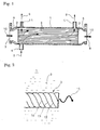
Fig. 1 is a sectional view showing an example of the EGR coolers in whichreference numeral 1 denotes a cylindrical shell with axially opposite ends to whichplates 2 are respectively fixed to close the ends of theshell 1. Penetratingly fixed to therespective plates 2 are opposite ends of a number oftubes 3 which extend axially within theshell 1. - Attached to the
shell 1 from outside are cooling water inlet andoutlet pipes shell 1, respectively, so that coolingwater 9 is fed via theinlet pipe 4 into theshell 1, flows outside of thetubes 3 and is discharged via theoutlet pipe 5 outside of theshell 1. - The
respective plates 2 have, on their sides away from theshell 1, bowl-shaped hoods 6 fixed to therespective plates 2 so as to enclose end faces of the plates. The one and theother hoods 6 provide central exhaust-gas inlet andoutlet exhaust gas 10 from the engine enters via theinlet 7 into the onehood 6, is cooled during passage through the number oftubes 3 by means of heat exchange with coolingwater 9 flowing outside of thetubes 3 and is discharged to theother hood 6 to be recirculated via theoutlet 8 to the engine. - In the figure,
reference numeral 11 denotes a bypass outlet pipe arranged at a position diametrically opposed to the coolingwater inlet pipe 4, part of thecooling water 9 being withdrawn through thebypass outlet pipe 11 so as to prevent thecooling water 9 from stagnating at the position diametrically opposed to the coolingwater inlet pipe 4. - Such conventional EGR cooler has poor heat exchange efficiency since the
exhaust gas 10 may flow straight in thetubes 3 and insufficiently contact inner peripheries of thetubes 3. Therefore, it has been proposed that an inner periphery of each of thetubes 3 is formed with spiral protrusions to causes theexhaust gas 10 passing through each of thetubes 3 to whirl, thereby increasing contact frequency and contact distance of theexhaust gas 10 to the inner periphery of each of thetubes 3 to enhance the heat exchange efficiency of the EGR cooler (see, for example,References 1 and 2).
[Reference 1]JP 2000-345925A
[Reference 2]JP 2001-254649A - However, a design concept conventionally adopted for formation of spiral protrusions on the inner periphery of each of the
tubes 3 is such that a pitch ratio of the spiral protrusions to an inner diameter of each of the tubes (an inclination angle of the spiral protrusion or protrusions to a plane perpendicular to an axis of each of the tubes 3) is minimized in merely focusing attention on initial performance value. It has been revealed from experimental results by the inventors that application of such design concept to an diesel engine, from which theexhaust gas 10 with much sooty contents is discharged, unsmooths the flow of theexhaust gas 10, resulting in accumulation of soot within thetubes 3 with lapse of time and thus substantial lowering of the heat exchange efficiency. - The invention was made in view of the above and has its object to provide an EGR cooler which can be satisfactorily applied to an diesel engine with no substantial lowering in performance.
- The invention is directed to an EGR cooler comprising tubes and a shell enclosing said tubes, cooling water being supplied to and discharged from said shell, exhaust gas being guided from a diesel engine into said tubes to be heat exchanged with said cooling water, characterized in that an inner periphery of each of said tubes is formed with three streaks of spiral protrusions running without crossing and with phases peripherally shifted or displaced with each other, a pitch ratio of each of said spiral protrusions to an inner diameter of each of said tubes being 2.0-4.0, a ridge height ratio of each of said spiral protrusions to said inner diameter of each of said tubes being 0.1-0.2.
- Such pitch ratio of each of the spiral protrusions to the inner diameter of each of the tubes set to 2.0-4.0 is slightly inferior in initial performance value on heat exchange efficiency to a pitch ratio of less than 2.0, but increases the tendency of each of the spiral protrusions slanting in the direction of the exhaust gas flow to keep the exhaust gas having less pressure loss and make the exhaust gas flow more smoothly with tendency of the soot being not accumulated on the inner periphery of each of the tubes, and therefore is superior in eventual performance value on heat exchange efficiency after final deterioration; in view of long use thereafter, it turns out that available is a prolonged time period with sufficient heat exchange efficiency maintained.
- In fact, it has been ascertained by the inventors' experiments that the pitch ratio of each of the spiral protrusions to the inner diameter of each of the tubes set to less than 2.0 increases the pressure loss with the tendency of soot being accumulated in the tubes, resulting in substantial lowering in performance. It has been also ensured that, with the pitch ratio of each of the spiral protrusions being in a range of 2.0-4.0, the eventual performance value after final deterioration substantially stays flat.
- On the other hand, it has been ensured that even with the pitch ratio of more than 4.0, it hardly contributes to lowering in pressure loss of the exhaust gas while an amount of heat exchanged tends to be drastically decreased by slight increase in pitch ratio (a number of whirl of the exhaust gas tends to be decreased due to excess slant of the spiral protrusions in the direction of the exhaust gas flow); moreover, insufficient whirling force afforded to the exhaust gas excessively impairs the action of the soot entrained in the exhaust gas gathering to the whirling axis, resulting inversely in a tendency of the soot to be accumulated on the inner periphery of each of the tubes.
- According to the invention, the inner periphery of each of the tubes is formed with three streaks of spiral protrusions running without crossing and with phases peripherally shifted to each other. This enables the mutual distance between the respective protrusions to be decreased with the pitch ratio of each of the spiral protrusions being more than 2.0, whereby whirling force of the exhaust gas can be increased without increasing the pressure loss.
- Theoretically, the more the number of streaks of spiral protrusions is, the more they work effectively. However, to machine three streaks of protrusions is actual limitation in current machining technology. It turns out that, at a practical level, such machining of three streaks of spiral protrusions can maximize eventual performance value after final deterioration.
- Upon setting the pitch ratio of each of the spiral protrusions to 2.0-4.0, it is preferable that a ridge height ratio of each of the spiral protrusions to the inner diameter of each of the tubes is set to 0.1-0.2. It has been ascertained by the inventors that, with the ridge height ratio being less than 0.1, whirling flow of the exhaust gas is hard to be sufficiently formed, resulting in lowering of an amount of heat exchanged to a minimum level; to increase the ridge height ratio to more than 0.2 is actually unattainable due to productive limitation.
- As is clear from the foregoing, various excellent features and advantages may be obtained according to an EGR cooler of the invention.
-
- (I) For improvement of heat exchange efficiency by means of whirling flow of the exhaust gas in the tubes, the pitch ratio of each of the spiral protrusions to the inner diameter of each of the tubes is set to 2.0-4.0 and the ridge height ratio of each of the spiral protrusions to the inner diameter of each of the tubes is set to 0.1-0.2, so that the soot can be suppressed from being accumulated on the inner periphery of each of the tubes. Thus, an EGR cooler can be provided which can keep performance value higher after final deterioration in comparison with an EGR cooler with the conventional design concept merely focusing attention on initial performance value and which is satisfactorily applicable to a diesel engine with highly sooty exhaust gas being discharged without substantial lowering in performance.
-
- (II) The three streaks of spiral protrusions are formed on the inner periphery of each of the tubes so as to run without crossing and with phases peripherally shifted to each other. As a result, while the pitch ratio of each of the spiral protrusions is set to more than 2.0, mutual distance between the respective spiral protrusions can be decreased and whirling force of the exhaust gas can be increased without pressure loss.
-
-
Fig. 1 is a sectional view showing a conventional EGR cooler; -
Fig. 2 is a side view showing an embodiment of the invention; -
Fig. 3 is a sectional view showing the spiral protrusions inFig. 2 ; -
Fig. 4 is a graph showing a relationship between heat exchange efficiency and a pitch P ratio (P/D); -
Fig. 5 is a view for explanation of a single spiral protrusion; -
Fig. 6 is a view for explanation of three spiral protrusions; and -
Fig. 7 is a graph showing a relationship between an amount of heat to be exchanged and a ratio of ridge height H (H/D). -
- 1
- shell
- 3
- tube
- 9
- cooling water
- 10
- exhaust gas
- 12
- spiral protrusion
- 13
- spiral protrusion
- 14
- spiral protrusion
- D
- inner diameter of tube
- H
- ridge height
- P
- pitch
- An embodiment of the invention will be described in conjunction with drawings.
Figs. 2 and3 show the embodiment of the invention in which parts similar to those inFig. 1 are designated by the same reference numerals. - As shown in
Fig. 2 , the embodiment is directed to an EGR cooler constructed substantially similarly to that has been explained with respect toFig. 1 , and an inner periphery of each oftubes 3 through whichexhaust gas 10 flows is formed with three streaks ofspiral protrusions spiral protrusions tubes 3 being set to 2.0-4.0. - Upon formation of each of the
spiral protrusions tubes 3 may be spirally indented from outside by means of, for example, a roll with spiral convex streaks, so that portions pressed from outside provide thespiral protrusions tube 3. - For setting, as shown in
Fig. 3 , the pitch P ratio (P/D) of each ofspiral protrusions tubes 3 to 2.0-4.0, it is preferable that ridge height H of each of thespiral protrusions tubes 3 has a ratio (H/D) to the inner diameter D of each of thetubes 3 set to 0.1-0.2. - Thus, such pitch P ratio (P/D) of each of the
spiral protrusions tubes 3 set to 2.0-4.0 is slightly inferior in initial performance value on heat exchange efficiency to a pitch P ratio (P/D) of less than 2.0, but increases the tendency of each of the spiral protrusions slanting in the direction of flow of theexhaust gas 10 to keep and cause theexhaust gas 10 to have less pressure loss and to flow smoothly with tendency of the soot not to be accumulated on the inner periphery of each of thetubes 3, and therefore is superior in eventual performance value on heat exchange efficiency after final deterioration; in view of long use thereafter, it turns out that available is a prolonged time period with sufficient heat exchange efficiency being maintained. - In fact, the inventors' experiments brought about the experimental results, for example, as graphically shown in
Fig. 4 (which shows a relationship between heat exchange efficiency and P/D (a pitch P ratio of each of thespiral protrusions spiral protrusions tubes 3 is set to less than 2.0, increase in pressure loss cause the soot to be easily accumulated in thetubes 3, resulting in substantial lowering in performance, and that, with the pitch P ratio (P/D) of each of thespiral protrusions - Here, performance value after final deterioration will be explained. With lapse of time from start of using the EGR cooler, accumulation of the soot in the
tubes 3 proceeds, which lowers heat exchange efficiency and increases pressure loss in theexhaust gas 10; eventually, a situation (saturation) is brought about where accumulation of the soot becomes not increased any more with the heat exchange efficiency and pressure loss being stabilized. Performance value in this situation is taken as performance value after final deterioration. - On the other hand, it has been ensured that even with the pitch P ratio (P/D) of more than 4.0, it hardly contribute to lowering in pressure loss of the exhaust gas while an amount of heat exchanged tends to be drastically decreased by slight increase in pitch P ratio (P/D) (a number of whirl of the
exhaust gas 10 tends to be decreased due to over-collapse of thespiral protrusions exhaust gas 10 excessively impairs the action of the soot entrained in theexhaust gas 10 gathering to the whirling axis, resulting inversely in a tendency of the soot to be accumulated on the inner periphery of each of thetubes 3. -
Fig. 4 graphically shows differences of initial performance value and performance value after final deterioration between two examples ofspiral protrusions - By reviewing an EGR cooler with proper size on the basis of the above-mentioned experimental results and in due consideration to mountability in an engine room, it turns out that most effective optimal condition is to specify a pitch P ratio (P/D) of each of the
spiral protrusions tubes 3 to 2.0-4.0. - When the pitch P ratio (P/D) of the
spiral protrusions tubes 3 is set to 2.0-4.0 and if, as schematically shown inFig. 5 , a single streak ofspiral protrusion 12 were applied, then axial pitch P of thespiral protrusion 12 would inevitably spatial with no spiral protrusion; as schematically shown inFig. 6 , if there are three streaks ofspiral protrusions spiral protrusions spiral protrusions exhaust gas 10 with no increase in pressure loss. - Theoretically, the more the number of streaks of
spiral protrusions spiral protrusions - Further, when the pitch P ratio (P/D) of each of the
spiral protrusions Fig. 7 , that a ridge height H ratio (H/D) of each of thespiral protrusions tubes 3 is set to 0.1-0.2. It has been ascertained by the inventors that, with the ridge height H ratio (H/D) being less than 0.1, whirling flow of theexhaust gas 10 is hard to be sufficiently formed, resulting in lowering of an amount of heat exchanged to a minimum level; to increase the ridge height H ratio (H/D) to more than 0.2 is actually unattainable due to productive limitation. - Thus, according to the embodiment, for improvement in heat exchange efficiency by means of the whirling flow of the
exhaust gas 10 in thetubes 3, the pitch P ratio (P/D) of each of thespiral protrusions tubes 3 is set to 2.0-4.0 and the ridge height H ratio (H/D) of each of thespiral protrusions tubes 3 is set to 0.1-0.2. As a result, the soot is suppressed from being accumulated on the inner periphery of each of thetubes 3 to keep performance value higher after final deterioration in comparison with an EGR cooler with a conventional design concept merely focusing attention on initial performance value, so that an EGR cooler is provided which is satisfactorily applicable to a diesel engine with highly sooty exhaust gas being discharged with no substantial lowering in performance. - Especially in the embodiment, the inner periphery of each of the
tubes 3 is formed with three streaks ofspiral protrusions respective spiral protrusions spiral protrusions exhaust gas 10 can be increased without increasing the pressure loss. - It is to be understood that an EGR cooler according to the invention is not limited to the above embodiment and that various changes and modifications may be made without leaving the spirit of the invention.
Claims (1)
- An EGR cooler comprising tubes (3) and a shell (1) enclosing said tubes (3), cooling water (9) being supplied to and discharged from said shell (1), exhaust gas (10) being guided from a diesel engine into said tubes (3) to be heat exchanged with said cooling water (9), characterized in that an inner periphery of each of said tubes (3) is formed with three streaks of spiral protrusions (12),(13),(14) running without crossing and with phases peripherally shifted or displaced with each other, a pitch (P) ratio of each of said spiral protrusions (12),(13),(14) to an inner diameter (D) of each of said tubes being 2.0-4.0, a ridge height (H) ratio of each of said spiral protrusions (12),(13),(14) to said inner diameter (D) of each of said tubes being 0.1-0.2.
Applications Claiming Priority (2)
| Application Number | Priority Date | Filing Date | Title |
|---|---|---|---|
| JP2005295010A JP2007100673A (en) | 2005-10-07 | 2005-10-07 | EGR cooler |
| PCT/JP2006/320058 WO2007043456A1 (en) | 2005-10-07 | 2006-10-06 | Egr cooler |
Publications (2)
| Publication Number | Publication Date |
|---|---|
| EP1933023A1 true EP1933023A1 (en) | 2008-06-18 |
| EP1933023A4 EP1933023A4 (en) | 2008-12-10 |
Family
ID=37942699
Family Applications (1)
| Application Number | Title | Priority Date | Filing Date |
|---|---|---|---|
| EP20060811385 Withdrawn EP1933023A4 (en) | 2005-10-07 | 2006-10-06 | Egr cooler |
Country Status (4)
| Country | Link |
|---|---|
| US (1) | US8079409B2 (en) |
| EP (1) | EP1933023A4 (en) |
| JP (1) | JP2007100673A (en) |
| WO (1) | WO2007043456A1 (en) |
Cited By (2)
| Publication number | Priority date | Publication date | Assignee | Title |
|---|---|---|---|---|
| DE102010032364A1 (en) | 2009-08-01 | 2011-02-03 | Ford Global Technologies, LLC, Dearborn | Exhaust gas recirculation arrangement |
| CN103758665A (en) * | 2013-12-31 | 2014-04-30 | 广西玉柴机器股份有限公司 | Arrangement structure of electric control EGR (Exhaust Gas Recirculation) system |
Families Citing this family (9)
| Publication number | Priority date | Publication date | Assignee | Title |
|---|---|---|---|---|
| DE102008002430C5 (en) * | 2007-07-11 | 2018-03-22 | Hanon Systems | Exhaust gas heat exchanger with vibration-damped exchanger tube bundle |
| DE102008001659B4 (en) * | 2007-07-11 | 2014-01-30 | Halla Visteon Climate Control Corp. | Exhaust gas heat exchanger with integrated mounting interface |
| US9605912B2 (en) | 2012-04-18 | 2017-03-28 | Kennieth Neal | Helical tube EGR cooler |
| US20140116668A1 (en) * | 2012-10-31 | 2014-05-01 | GM Global Technology Operations LLC | Cooler pipe and method of forming |
| US9964077B2 (en) | 2013-04-16 | 2018-05-08 | Kennieth Neal | Helical tube EGR cooler |
| JP6011499B2 (en) * | 2013-09-13 | 2016-10-19 | 株式会社デンソー | Adsorber |
| US9670830B2 (en) * | 2014-10-29 | 2017-06-06 | GM Global Technology Operations LLC | Method and apparatus for monitoring a coolant system for an exhaust gas recirculation system |
| JP6868146B1 (en) * | 2020-06-29 | 2021-05-12 | 株式会社クボタ | Pyrolysis tube with fluid agitation element |
| CN114719635B (en) * | 2022-04-28 | 2023-11-03 | 广西玉柴动力股份有限公司 | A heat exchange method and device for the exhaust pipe of a high-speed boat engine |
Family Cites Families (13)
| Publication number | Priority date | Publication date | Assignee | Title |
|---|---|---|---|---|
| US2252045A (en) * | 1938-10-18 | 1941-08-12 | Spanner Edward Frank | Tubular heat exchange apparatus |
| US3826304A (en) * | 1967-10-11 | 1974-07-30 | Universal Oil Prod Co | Advantageous configuration of tubing for internal boiling |
| US4330036A (en) * | 1980-08-21 | 1982-05-18 | Kobe Steel, Ltd. | Construction of a heat transfer wall and heat transfer pipe and method of producing heat transfer pipe |
| JPH09152290A (en) * | 1995-11-29 | 1997-06-10 | Sanyo Electric Co Ltd | Absorption refrigerating machine |
| JPH11108578A (en) | 1997-09-30 | 1999-04-23 | Usui Internatl Ind Co Ltd | Egr gas cooler |
| US20030111209A1 (en) * | 1999-01-20 | 2003-06-19 | Hino Motors, Ltd. | EGR cooler |
| JP2000345925A (en) | 1999-06-04 | 2000-12-12 | Hino Motors Ltd | EGR cooler |
| JP2001254649A (en) | 2000-03-13 | 2001-09-21 | Hino Motors Ltd | EGR cooler |
| JP2001304047A (en) * | 2000-04-24 | 2001-10-31 | Usui Internatl Ind Co Ltd | Egr gas cooling device |
| JP2001342909A (en) | 2000-06-05 | 2001-12-14 | Hino Motors Ltd | EGR cooler |
| JP2004028376A (en) * | 2002-06-21 | 2004-01-29 | Hino Motors Ltd | EGR cooler |
| US7171956B2 (en) * | 2002-08-28 | 2007-02-06 | T. Rad Co., Ltd. | EGR cooler |
| US20040244958A1 (en) * | 2003-06-04 | 2004-12-09 | Roland Dilley | Multi-spiral upset heat exchanger tube |
-
2005
- 2005-10-07 JP JP2005295010A patent/JP2007100673A/en active Pending
-
2006
- 2006-10-06 EP EP20060811385 patent/EP1933023A4/en not_active Withdrawn
- 2006-10-06 US US12/088,988 patent/US8079409B2/en not_active Expired - Fee Related
- 2006-10-06 WO PCT/JP2006/320058 patent/WO2007043456A1/en not_active Ceased
Cited By (3)
| Publication number | Priority date | Publication date | Assignee | Title |
|---|---|---|---|---|
| DE102010032364A1 (en) | 2009-08-01 | 2011-02-03 | Ford Global Technologies, LLC, Dearborn | Exhaust gas recirculation arrangement |
| US8528529B2 (en) | 2009-08-01 | 2013-09-10 | Ford Global Technologies, Llc | Exhaust gas recirculation cooler |
| CN103758665A (en) * | 2013-12-31 | 2014-04-30 | 广西玉柴机器股份有限公司 | Arrangement structure of electric control EGR (Exhaust Gas Recirculation) system |
Also Published As
| Publication number | Publication date |
|---|---|
| US8079409B2 (en) | 2011-12-20 |
| WO2007043456A1 (en) | 2007-04-19 |
| EP1933023A4 (en) | 2008-12-10 |
| US20090229802A1 (en) | 2009-09-17 |
| JP2007100673A (en) | 2007-04-19 |
Similar Documents
| Publication | Publication Date | Title |
|---|---|---|
| US7080634B2 (en) | EGR cooler | |
| US7594536B2 (en) | EGR cooler | |
| CN100526789C (en) | Exhaust gas heat exchanger, in particular exhaust gas cooler for exhaust gas recirculation of motor vehicles | |
| EP2025913B1 (en) | Three-pass heat exchanger for an EGR system | |
| US20090090486A1 (en) | Heat exchanger for a motor vehicle | |
| US8079409B2 (en) | EGR cooler | |
| US11179662B2 (en) | Gas-liquid separator | |
| JP2001027157A (en) | Structure of EGR cooler | |
| JP2005273564A (en) | Exhaust gas recirculation device | |
| JP4386215B2 (en) | EGR gas cooling device | |
| JP2006118436A (en) | Bonnet for egr gas cooling device | |
| JP4345470B2 (en) | Engine EGR cooler | |
| JP2005273512A (en) | Engine EGR cooler | |
| JP4248095B2 (en) | EGR cooler | |
| EP2764231B1 (en) | Heat exchanger for gases, especially engine exhaust gases | |
| JP2002310007A (en) | EGR gas cooling structure | |
| JP2002180915A (en) | EGR cooler | |
| US20080245502A1 (en) | Heat Exchanger | |
| CN204327322U (en) | Cooler for recycled exhaust gas | |
| JP2001254649A (en) | EGR cooler | |
| CN110017711A (en) | Equipment and its manufacturing method for heat transmitting | |
| CN200962008Y (en) | A pipe shell heat exchanger for U-shape cross spiral pipe | |
| CN100497924C (en) | Exhaust gas recirculation cooler | |
| JPH0988731A (en) | Egr gas cooling system | |
| JP2009024499A (en) | EGR cooler |
Legal Events
| Date | Code | Title | Description |
|---|---|---|---|
| PUAI | Public reference made under article 153(3) epc to a published international application that has entered the european phase |
Free format text: ORIGINAL CODE: 0009012 |
|
| 17P | Request for examination filed |
Effective date: 20080328 |
|
| AK | Designated contracting states |
Kind code of ref document: A1 Designated state(s): DE FR GB |
|
| A4 | Supplementary search report drawn up and despatched |
Effective date: 20081112 |
|
| DAX | Request for extension of the european patent (deleted) | ||
| RBV | Designated contracting states (corrected) |
Designated state(s): DE FR GB |
|
| 17Q | First examination report despatched |
Effective date: 20090302 |
|
| STAA | Information on the status of an ep patent application or granted ep patent |
Free format text: STATUS: THE APPLICATION IS DEEMED TO BE WITHDRAWN |
|
| 18D | Application deemed to be withdrawn |
Effective date: 20090914 |