EP1932946A2 - Magnesium alloy part and production method thereof - Google Patents
Magnesium alloy part and production method thereof Download PDFInfo
- Publication number
- EP1932946A2 EP1932946A2 EP20070022146 EP07022146A EP1932946A2 EP 1932946 A2 EP1932946 A2 EP 1932946A2 EP 20070022146 EP20070022146 EP 20070022146 EP 07022146 A EP07022146 A EP 07022146A EP 1932946 A2 EP1932946 A2 EP 1932946A2
- Authority
- EP
- European Patent Office
- Prior art keywords
- magnesium alloy
- paint film
- part body
- magnesium
- weight
- Prior art date
- Legal status (The legal status is an assumption and is not a legal conclusion. Google has not performed a legal analysis and makes no representation as to the accuracy of the status listed.)
- Granted
Links
Images




Classifications
-
- C—CHEMISTRY; METALLURGY
- C23—COATING METALLIC MATERIAL; COATING MATERIAL WITH METALLIC MATERIAL; CHEMICAL SURFACE TREATMENT; DIFFUSION TREATMENT OF METALLIC MATERIAL; COATING BY VACUUM EVAPORATION, BY SPUTTERING, BY ION IMPLANTATION OR BY CHEMICAL VAPOUR DEPOSITION, IN GENERAL; INHIBITING CORROSION OF METALLIC MATERIAL OR INCRUSTATION IN GENERAL
- C23C—COATING METALLIC MATERIAL; COATING MATERIAL WITH METALLIC MATERIAL; SURFACE TREATMENT OF METALLIC MATERIAL BY DIFFUSION INTO THE SURFACE, BY CHEMICAL CONVERSION OR SUBSTITUTION; COATING BY VACUUM EVAPORATION, BY SPUTTERING, BY ION IMPLANTATION OR BY CHEMICAL VAPOUR DEPOSITION, IN GENERAL
- C23C22/00—Chemical surface treatment of metallic material by reaction of the surface with a reactive liquid, leaving reaction products of surface material in the coating, e.g. conversion coatings, passivation of metals
- C23C22/05—Chemical surface treatment of metallic material by reaction of the surface with a reactive liquid, leaving reaction products of surface material in the coating, e.g. conversion coatings, passivation of metals using aqueous solutions
- C23C22/06—Chemical surface treatment of metallic material by reaction of the surface with a reactive liquid, leaving reaction products of surface material in the coating, e.g. conversion coatings, passivation of metals using aqueous solutions using aqueous acidic solutions with pH less than 6
- C23C22/34—Chemical surface treatment of metallic material by reaction of the surface with a reactive liquid, leaving reaction products of surface material in the coating, e.g. conversion coatings, passivation of metals using aqueous solutions using aqueous acidic solutions with pH less than 6 containing fluorides or complex fluorides
-
- C—CHEMISTRY; METALLURGY
- C23—COATING METALLIC MATERIAL; COATING MATERIAL WITH METALLIC MATERIAL; CHEMICAL SURFACE TREATMENT; DIFFUSION TREATMENT OF METALLIC MATERIAL; COATING BY VACUUM EVAPORATION, BY SPUTTERING, BY ION IMPLANTATION OR BY CHEMICAL VAPOUR DEPOSITION, IN GENERAL; INHIBITING CORROSION OF METALLIC MATERIAL OR INCRUSTATION IN GENERAL
- C23C—COATING METALLIC MATERIAL; COATING MATERIAL WITH METALLIC MATERIAL; SURFACE TREATMENT OF METALLIC MATERIAL BY DIFFUSION INTO THE SURFACE, BY CHEMICAL CONVERSION OR SUBSTITUTION; COATING BY VACUUM EVAPORATION, BY SPUTTERING, BY ION IMPLANTATION OR BY CHEMICAL VAPOUR DEPOSITION, IN GENERAL
- C23C22/00—Chemical surface treatment of metallic material by reaction of the surface with a reactive liquid, leaving reaction products of surface material in the coating, e.g. conversion coatings, passivation of metals
- C23C22/82—After-treatment
- C23C22/83—Chemical after-treatment
-
- C—CHEMISTRY; METALLURGY
- C23—COATING METALLIC MATERIAL; COATING MATERIAL WITH METALLIC MATERIAL; CHEMICAL SURFACE TREATMENT; DIFFUSION TREATMENT OF METALLIC MATERIAL; COATING BY VACUUM EVAPORATION, BY SPUTTERING, BY ION IMPLANTATION OR BY CHEMICAL VAPOUR DEPOSITION, IN GENERAL; INHIBITING CORROSION OF METALLIC MATERIAL OR INCRUSTATION IN GENERAL
- C23C—COATING METALLIC MATERIAL; COATING MATERIAL WITH METALLIC MATERIAL; SURFACE TREATMENT OF METALLIC MATERIAL BY DIFFUSION INTO THE SURFACE, BY CHEMICAL CONVERSION OR SUBSTITUTION; COATING BY VACUUM EVAPORATION, BY SPUTTERING, BY ION IMPLANTATION OR BY CHEMICAL VAPOUR DEPOSITION, IN GENERAL
- C23C28/00—Coating for obtaining at least two superposed coatings either by methods not provided for in a single one of groups C23C2/00 - C23C26/00 or by combinations of methods provided for in subclasses C23C and C25C or C25D
- C23C28/04—Coating for obtaining at least two superposed coatings either by methods not provided for in a single one of groups C23C2/00 - C23C26/00 or by combinations of methods provided for in subclasses C23C and C25C or C25D only coatings of inorganic non-metallic material
-
- Y—GENERAL TAGGING OF NEW TECHNOLOGICAL DEVELOPMENTS; GENERAL TAGGING OF CROSS-SECTIONAL TECHNOLOGIES SPANNING OVER SEVERAL SECTIONS OF THE IPC; TECHNICAL SUBJECTS COVERED BY FORMER USPC CROSS-REFERENCE ART COLLECTIONS [XRACs] AND DIGESTS
- Y10—TECHNICAL SUBJECTS COVERED BY FORMER USPC
- Y10T—TECHNICAL SUBJECTS COVERED BY FORMER US CLASSIFICATION
- Y10T428/00—Stock material or miscellaneous articles
- Y10T428/12—All metal or with adjacent metals
- Y10T428/12493—Composite; i.e., plural, adjacent, spatially distinct metal components [e.g., layers, joint, etc.]
- Y10T428/12729—Group IIA metal-base component
-
- Y—GENERAL TAGGING OF NEW TECHNOLOGICAL DEVELOPMENTS; GENERAL TAGGING OF CROSS-SECTIONAL TECHNOLOGIES SPANNING OVER SEVERAL SECTIONS OF THE IPC; TECHNICAL SUBJECTS COVERED BY FORMER USPC CROSS-REFERENCE ART COLLECTIONS [XRACs] AND DIGESTS
- Y10—TECHNICAL SUBJECTS COVERED BY FORMER USPC
- Y10T—TECHNICAL SUBJECTS COVERED BY FORMER US CLASSIFICATION
- Y10T428/00—Stock material or miscellaneous articles
- Y10T428/31504—Composite [nonstructural laminate]
- Y10T428/31678—Of metal
Definitions
- the present invention relates to magnesium alloy parts, and in particular to magnesium alloy parts having a paint film.
- the present invention also relates to a production method for such magnesium alloy parts.
- steels i.e., iron alloys containing carbon
- iron alloys containing carbon have frequently been used as component parts of transportation apparatuses because they excel in mechanical properties and ease of manufacturing while being inexpensive.
- the light-weight property of transportation apparatuses has been an issue in improving the mileage (fuel consumption) and running properties thereof, and use of materials that are lighter than iron has been under study.
- magnesium has a density which is about 23% of that of iron. Therefore, the weight of a transportation apparatus can be greatly reduced by using magnesium or a magnesium alloy.
- a paint film for protective or decorative purposes is provided on the surface of a magnesium alloy part.
- Electrostatic painting, electropainting, and the like are known methods for forming a paint film on the surface of a magnesium alloy.
- electropainting is able to uniformly form a paint film, and therefore is suitably used for parts with complex outer shapes.
- Japanese Laid-Open Patent Publication No. 2005-146329 discloses a technique of consecutively subjecting the surface of a magnesium alloy to an etching treatment with an organic acid and then a treatment with an aqueous solution of fluoride, followed by a conversion coating treatment with an aqueous solution of phosphate, thus reducing the electrical resistance and improving the painting anti-corrosiveness and paintability of the conversion coating.
- Japanese Laid-Open Patent Publication No. 2001-172772 discloses a technique of immersing a magnesium alloy in a treatment liquid containing a fluorochemical, to which a surface tension reducer is added, thus forming a conversion coating having an excellent anti-corrosiveness and smoothness on the surface of the magnesium alloy.
- preferred embodiments of the present invention improve the adhesion of a paint film which is formed on the surface of a magnesium alloy part.
- a magnesium alloy part according to a preferred embodiment of the present invention preferably includes a part body composed of a magnesium alloy containing aluminum; a paint film at least partially covering the part body; and a magnesium fluoride layer provided immediately under the paint film, wherein the magnesium alloy has an aluminum content of about 6.5 weight% or less.
- the magnesium alloy has an aluminum content of about 4.4 weight% or more.
- the paint film is formed by electropainting.
- an aluminum content in a region down to a depth of approximately 30 ⁇ m from a surface of the part body is about 5.0 weight% or less.
- the magnesium fluoride layer has a surface roughness of no less than about 1.6Rz JIS and no more than about 50Rz JIS .
- the magnesium fluoride layer is formed on a surface of the part body by a conversion treatment.
- a transportation apparatus includes a magnesium alloy part having the aforementioned construction.
- a production method for a magnesium alloy part preferably includes the steps of providing a part body which is composed of a magnesium alloy containing about 6.5 weight% or less of aluminum; forming a magnesium fluoride layer on a surface of the part body by immersing the part body in a solution containing a fluorochemical; and forming a paint film immediately above the magnesium fluoride layer.
- the step of forming a paint film is conducted by electropainting.
- the method further includes, before the step of forming the magnesium fluoride layer, a step of etching the surface of the part body.
- the magnesium alloy part according to various preferred embodiments of the present invention includes a magnesium fluoride layer which is provided immediately under a paint film. Therefore, the paint film exhibits a high adhesion as compared to a magnesium alloy part in which a paint film is formed upon a phosphate coating.
- the part body of the magnesium alloy part according to preferred embodiments of the present invention is composed of a magnesium alloy having an aluminum content of about 6.5 weight% or less. Therefore, lowering of the adhesion of the paint film due to any unstable aluminum fluoride that may be formed on the surface of the part body is prevented.
- the paint film which is formed on the surface of the magnesium alloy part has an improved adhesion (i.e., reluctance to peel).
- the magnesium alloy has an aluminum content of about 4.4 weight% or more.
- the inventive effect of improving the adhesion of a paint film becomes particularly prominent in the case where the paint film is formed by electropainting.
- the effect of suppressing aluminum fluoride formation on the surface of the part body is enhanced, whereby adhesion of the paint film can be further improved.
- the magnesium fluoride layer which is provided immediately under the paint film has a large surface roughness (preferably about 1.6Rz JIS or more).
- the magnesium fluoride layer has a surface roughness of about 50Rz JIS or less.
- the magnesium fluoride layer has a surface roughness (ten point-average roughness) of no less than about 1.6Rz JIS and no more than about 50Rz JIS .
- the magnesium fluoride layer of the magnesium alloy part according to preferred embodiments of the present invention is typically formed by a conversion treatment.
- the magnesium alloy part according to preferred embodiments of the present invention is excellent in terms of adhesion of the paint film, and therefore is suitably used for transportation apparatuses. Since transportation apparatuses are to be used mainly outdoor, their component parts are often subjected to harsh environments. However, by using the magnesium alloy part according to preferred embodiments of the present invention, it becomes possible to realize a light-weight transportation apparatus while preventing peeling of the paint film in harsh environments, thus improving the durability of the transportation apparatus.
- a paint film is formed immediately above the magnesium fluoride layer.
- the adhesion of the paint film can be enhanced as compared to a technique of forming a paint film upon a phosphate coating.
- the part body to be provided is composed of a magnesium alloy containing about 6.5 weight% or less of aluminum. Therefore, lowering of the adhesion of the paint film due to any unstable aluminum fluoride that may be formed on the surface of the part body is prevented.
- the paint film which is formed on the surface of the magnesium alloy part has an improved adhesion (i.e., reluctance to peel).
- the inventive effect of improving the adhesion of a paint film becomes particularly prominent in the case where the step of forming the paint film is conducted by electropainting.
- the paint film which is formed on the surface of the magnesium alloy part has an improved adhesion (i.e., reluctance to peel).
- FIG. 1 is a schematic diagram showing a cross-sectional structure of a magnesium alloy part 10 according to a preferred embodiment of the present invention.
- FIGS. 2A to 2D are step-by-step cross-sectional views schematically showing production steps of the magnesium alloy part 10.
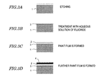
- FIGS. 3A to 3D are step-by-step cross-sectional views schematically showing production steps of the magnesium alloy part 10.
- FIG. 4 is a graph showing a depth-direction element distribution after a treatment with an aqueous solution of fluoride, analyzed by ESCA.
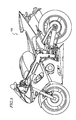
- FIG. 5 is a side view schematically showing a motorcycle.
- FIGS. 6A and 6B are a perspective view and a side view, respectively, schematically showing a frame of a motorcycle.
- FIG. 7 is an exploded perspective view schematically showing a crankcase.
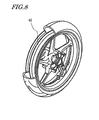
- FIG. 8 is a perspective view schematically showing a wheel.
- FIG. 1 shows a cross-sectional structure of a magnesium alloy part (which hereinafter may simply be referred to as a "part") 10 according to the present preferred embodiment.
- the part 10 includes a part body 1, a paint film 2 at least partially covering the part body 1, and a magnesium fluoride layer 3 provided immediately under the paint film 2.
- the magnesium fluoride layer 3 and the paint film 2 are stacked in this order.
- the part body 1 preferably is composed of a magnesium alloy containing aluminum.
- the part body 1 preferably is molded into a predetermined shape by casting, for example.
- the magnesium fluoride (MgF 2 ) layer 3 is preferably formed on the surface of the part body 1 by a conversion treatment.
- the paint film 2 is formed immediately above the magnesium fluoride layer 3.
- a phosphate conversion coating is formed by a conversion coating treatment using an aqueous solution of phosphate, as in the technique disclosed in Japanese Laid-Open Patent Publication No. 2005-146329 , the paint film may peel in a humidity test. This is considered because, under harshly humid conditions, the phosphate conversion coating reacts with water and becomes unstable.
- the magnesium fluoride layer 3 is provided immediately under the paint film 2.
- the paint film 2 is formed immediately above the magnesium fluoride layer 3. Since the magnesium fluoride layer 3 is more stable in a humid environment than a phosphate conversion coating, the magnesium alloy part 10 of the present preferred embodiment exhibits a strong adhesion of the paint film 2 as compared to a magnesium alloy part which is composed of a phosphate conversion coating having a paint film provided thereon.
- the part body 1 is composed of a magnesium alloy whose aluminum content accounts for a predetermined value or less, specifically, a magnesium alloy having an aluminum content of about 6.5 weight% or less. As a result, lowering of the adhesion of the paint film 2, which is associated with an unstable aluminum fluoride that is formed on the surface of the part body 1, is prevented.
- preferred embodiments of the present invention provides an improved adhesion (i.e., reluctance to peel) of the paint film 2 which is formed on the surface of the magnesium alloy part 10.
- FIGS. 2A to 2D and FIGS. 3A to 3D are step-by-step cross-sectional views schematically showing production steps of the part 10.
- a part body 1 which is formed of a magnesium alloy containing about 6.5 weight% or less of aluminum.
- AZ31B, AM60B, or AM50A may be used as the magnesium alloy containing about 6.5 weight% or less of aluminum.
- the magnesium alloys exemplified herein have compositions as shown (in weight%) in Table 1 below.
- the part body 1 has been molded into a predetermined shape by casting, for example. On the surface of the part body 1 fresh from casting, as shown in FIG. 2A, there are a contamination layer 11 which may have originated in a release agent that was applied on the die, etc., and some abnormal structures which may have occurred during casting.
- the magnesium alloy has an aluminum content of about 2.5 weight% or more. From the standpoint of realizing a high castability, it is preferable that the magnesium alloy has an aluminum content of about 4.4 weight% or more.
- the surface of the part body 1 is subjected to a blast treatment, such as shot blasting, in order to remove the contamination layer 11 and abnormal structures.
- This blast treatment also provides for a uniform exterior appearance of the part body 1 and removes small burrs.
- zinc (Zn) spheres having a diameter of about 0.6mm may be used as a shot medium 12, for example.
- the shooting speed and shooting density may be selected according to the size and purpose of the part 10 to be produced, the composition of the magnesium alloy, and the like.
- the shot medium 12 may be shot by a known method, e.g., centrifugal force, compressed air, or hydraulic technique.
- alkaline degreasing a cleaning with an alkaline solution
- An alkaline degreasing can be performed by, for example, immersing the part body 1 for about five minutes in a strong alkaline 15% aqueous solution (GFMG15SX from MILLION CHEMICAL CO.,LTD.), which serves as an alkaline solution (degreaser), while maintaining the aqueous solution at about 70°C.
- a strong alkaline 15% aqueous solution GMG15SX from MILLION CHEMICAL CO.,LTD.
- the surface of the part body is etched. This etching is performed to remove any release agent remaining on the surface of the part body 1 and any alloy segregation layer formed on the surface of the part body 1.
- the treatment liquid etchant
- a 2% aqueous solution of phosphoric acid can be used, for example. Such an etching with an aqueous solution of phosphoric acid may be performed for approximately one to five minutes, for example.
- the part body 1 is immersed in a solution containing a fluorochemical (aqueous solution of fluoride), thus forming a magnesium fluoride layer 3 on the surface of the part body 1.
- a fluorochemical aqueous solution of fluoride
- any iron and nickel which may have always been contained in the magnesium alloy or migrated from the die
- Formation of the magnesium fluoride layer 3 improves the anti-corrosiveness of the surface of the part body 1, and improves the adhesion of the paint film 2.
- aqueous solution of fluoride various kinds of aqueous solutions containing a fluorochemical can be used. For example, about 10% to about 30% (preferably about 20%) hydrofluoric acid (HF aqueous solution) can be used. It is also preferable to add a surface tension reducer (e.g., ethanol) to the aqueous solution of fluoride. Addition of a surface tension reducer will lower the surface tension of the aqueous solution of fluoride, thus making it easy to uniformly form the magnesium fluoride layer 3 even over the cold shuts and flow lines (which are surface defects that may be formed during casting), if any, of the part body 1.
- a surface tension reducer e.g., ethanol
- the temperature of the aqueous solution of fluoride only need to be maintained at a temperature such that the chemical reaction of the fluorochemical with the magnesium which is contained in the part body 1 occurs a moderate rate, e.g., about 10°C to about 40°C.
- the immersion time is to be appropriately set depending on the desired thickness of the magnesium fluoride layer 3. In order to ensure a sufficient anti-corrosiveness, it is preferable that the magnesium fluoride layer 3 is formed to a thickness of no less than about 0.1 ⁇ m and no more than about 1 ⁇ m, and the immersion time is about one to ten minutes, for example.
- the paint film 2 is formed on the magnesium fluoride layer 3, whereby the magnesium alloy part 10 is completed.
- the paint film 2 adds a design to the exterior appearance of the part 10, and ensures anti-corrosiveness of the part 10.
- electrostatic painting or electropainting may be used as a method of forming the paint film 2
- the problematic peeling of the paint film of a conventional magnesium alloy part is more likely to occur in electropainting, which is a type of immersion painting, than in electrostatic painting, which is a type of spray painting. Therefore, the inventive effect of improving the adhesion of the paint film 2 becomes more prominent in the case where the paint film 2 is formed by electropainting.
- a further paint film 4 may be formed by providing a top coating, as shown in FIG. 3D.
- Table2 below shows evaluation results of paint film adhesion with respect to the followings: Examples 1 to 3, in which the magnesium alloy had an aluminum content of about 6.5 weight% % or less and a magnesium fluoride layer was formed as a primary treatment; Comparative Examples 1 to 4, in which a manganese calcium phosphate-type conversion coating was formed as a primary treatment; and Comparative Examples 5 and 6, in which a magnesium fluoride layer was formed as a primary treatment but the magnesium alloy had an aluminum content over 6.5 weight% (specifically, 9.7 weight%). Note that the adhesion evaluations of the paint film were made according to JIS K5600-7-2 (corresponding international standard: IS06270 ), under the conditions of 95% humidity and 100% humidity.
- JIS K5600-7-2 corresponding international standard: IS06270
- the magnesium fluoride layer 3 is formed as a primary treatment, and the aluminum content of the magnesium alloy is prescribed to be about 6.5 weight% or less, whereby the paint film 2 maintains a high level of adhesion under harsh environments, irrespective of the method for forming the paint film 2.
- the anti-corrosiveness of magnesium alloys per se it is known that a higher aluminum content results in a higher anti-corrosiveness.
- the present preferred embodiment purposely prescribes a smaller aluminum content (specifically, about 6.5 weight% or less) in order to enhance the adhesion of the paint film 2, as a result of which the magnesium alloy part 10 achieves an enhanced anti-corrosiveness as a whole.
- Table 3 shows evaluation results of paint film adhesion and part body castability with respect to Examples 4 to 6 and Comparative Example 7, in each of which the part body was molded by casting one of various kinds of magnesium alloys with different aluminum contents, and a magnesium fluoride layer was formed as a primary treatment. Note that, the paint film was formed by electropainting. As in Table 2, the adhesion evaluations of the paint film were made according to JIS K5600-7-2 (corresponding international standard: IS06270 ), under the 100% humidity condition. Each paint film was partitioned into one hundred cells with cutting lines. Each numerical value shown in the adhesion evaluation column of Table 3 indicates the number of cells where the paint film showed peeling.
- Example 4 As can be seen from Table 3, in Comparative Example 7 having an aluminum content from 8.3 to 9.7 weight% (i.e., exceeding about 6.5 weight%), all cells showed peeling of the paint film. On the other hand, in Examples 4 to 6 having an aluminum content of about 6.5 weight% or less, none of the cells showed peeling of the paint film. However, Example 4 exhibited some casting defects when casting the part body 1, thus resulting in a lower moldability. Therefore, from the standpoint of enhancing the castability, it is preferable that the magnesium alloy has an aluminum content of about 4.4 weight% or more, as in Examples 5 and 6.
- the magnesium fluoride layer 3 which is provided immediately under the paint film 2, has a surface roughness (ten point-average roughness) of about 1.6Rz JIS or more.
- the magnesium fluoride layer 3 has a surface roughness not exceeding about 50Rz JIS .
- the magnesium fluoride layer has a surface roughness of no less than about 1.6Rz JIS and no more than about 50Rz JIS .
- the surface roughness of the magnesium fluoride layer 3 reflects the surface roughness of the part body 1, it is possible to ensure that the magnesium fluoride layer 3 has a surface roughness of no less than about 1.6Rz JIS and no more than about 50Rz JIS by ensuring that the surface roughness of the part body 1 is no less than about 1.6Rz JIS and no more than about 50Rz JIS before performing the step of forming the magnesium fluoride layer 3.
- the concentration and temperature of the treatment liquid and the treatment time may be adjusted so that the part body 1 after etching has a surface roughness of no less than about 1.6Rz JIS and no more than about 50Rz JIS.
- a mechanical polish may be conducted on the surface of the part body 1 before the etching step.
- the magnesium alloy which is the material composing the part body 1 has an aluminum content of about 6.5 weight% or less, formation of aluminum fluoride on the surface of the part body 1 can be prevented, whereby the adhesion of the paint film 2 can be improved.
- performing a step of etching the surface of the part body 1 before the step of forming the magnesium fluoride layer 3 can easily reduce the aluminum content near the surface of the part body 1.
- Etching the surface of the part body 1 removes and reduces the magnesium near the surface of the part body 1, which in turn results in an increased aluminum content near the surface.
- the aluminum near the surface will be more effectively removed. This makes it easy to reduce the aluminum content near the surface of the part body 1.
- the aluminum content near the surface of the part body 1 can be reduced even more easily.
- Table 4 below shows the aluminum content (average value) in the region down to a depth of approximately 30 ⁇ m from the surface of the part body 1 (which surface will later become an interface between the magnesium fluoride layer 3 and the part body 1) with respect to the following examples: Example 7, in which etching was not performed before step of forming the magnesium fluoride layer 3; Example 8, in which etching was performed by using an aqueous solution of organic acid; and Example 9, in which etching was performed by using an aqueous solution of phosphoric acid.
- Example 7 performing the etching reduces the aluminum content near the surface of the part body 1.
- use of an aqueous solution of phosphoric acid as the treatment liquid permits a greater reduction in the aluminum content near the surface (e.g., to 5 weight% or less as shown in Table4) than does an aqueous solution of organic acid.
- the aluminum content near the surface of the part body 1 can be reduced by etching the surface of the part body 1 before the step of forming the magnesium fluoride layer 3.
- the aluminum content near the surface of the part body 1 a region down to a depth of approximately 30 ⁇ m from the surface
- the aluminum content in the region down to a depth of approximately 30 ⁇ m from the surface of the part body 1 is about 1.0 weight% or more.
- the magnesium alloy part 10 of the present preferred embodiment is excellent in terms of adhesion of the paint film 2, and therefore is suitably used for various kinds of transportation apparatuses, such as a motorcycle 100 shown in FIG. 5.
- the magnesium alloy part 10 of the present preferred embodiment may be a frame 20 of a motorcycle as shown in FIGS. 6A and 6B, for example.
- the magnesium alloy part 10 of the present preferred embodiment may be a crankcase 30 as shown in FIG. 7, or a wheel 40 as shown in FIG. 8. It will be appreciated that, without being limited to those which are exemplified herein, the magnesium alloy part 10 of the present preferred embodiment can be suitably used as various parts of transportation apparatuses.
- the adhesion (reluctance to peel) of a paint film which is formed on the surface of a magnesium alloy part can be improved.
- the magnesium alloy part according to various preferred embodiments of the present invention can be widely used in various types of transportation apparatuses such as vehicles (e.g., motorcycles and four-wheeled automobiles), boats and airplanes.
- vehicles e.g., motorcycles and four-wheeled automobiles
- boats and airplanes e.g., airplanes.
Landscapes
- Chemical & Material Sciences (AREA)
- Metallurgy (AREA)
- Chemical Kinetics & Catalysis (AREA)
- Engineering & Computer Science (AREA)
- Materials Engineering (AREA)
- Mechanical Engineering (AREA)
- Organic Chemistry (AREA)
- General Chemical & Material Sciences (AREA)
- Inorganic Chemistry (AREA)
- Chemical Treatment Of Metals (AREA)
- Other Surface Treatments For Metallic Materials (AREA)
- Application Of Or Painting With Fluid Materials (AREA)
- Laminated Bodies (AREA)
- Superstructure Of Vehicle (AREA)
Abstract
Description
- The present invention relates to magnesium alloy parts, and in particular to magnesium alloy parts having a paint film. The present invention also relates to a production method for such magnesium alloy parts.
- Conventionally, steels (i.e., iron alloys containing carbon) have frequently been used as component parts of transportation apparatuses because they excel in mechanical properties and ease of manufacturing while being inexpensive. However, the light-weight property of transportation apparatuses has been an issue in improving the mileage (fuel consumption) and running properties thereof, and use of materials that are lighter than iron has been under study.
- In recent years, inexpensive refining methods for titanium, aluminum, magnesium, etc., which have smaller specific gravities than that of iron, and production methods for alloys containing such metals, have been developed. Moreover, techniques for improving the mechanical strength and ease of manufacturing of these metals and their alloys have also been developed.
- Therefore, use of titanium, aluminum, or magnesium as a material of component parts of transportation apparatuses has been proposed. In particular, magnesium has a density which is about 23% of that of iron. Therefore, the weight of a transportation apparatus can be greatly reduced by using magnesium or a magnesium alloy.
- In many cases, a paint film for protective or decorative purposes is provided on the surface of a magnesium alloy part. Electrostatic painting, electropainting, and the like are known methods for forming a paint film on the surface of a magnesium alloy. In particular, electropainting is able to uniformly form a paint film, and therefore is suitably used for parts with complex outer shapes.
- Methods for forming a painting underlayer on a magnesium alloy are proposed in
Japanese Laid-Open Patent Publication Nos. 2005-146329 2001-172772 -
Japanese Laid-Open Patent Publication No. 2005-146329 - Moreover,
Japanese Laid-Open Patent Publication No. 2001-172772 - By using a conversion coating which is formed by either of the techniques of
Japanese Laid-Open Patent Publication Nos. 2005-146329 2001-172772 - However, since transportation apparatuses are to be used mainly outdoor, their component parts are often subjected to harsh environments. This fact has led to the desire for a further improved adhesion (i.e., a stronger reluctance to peel) of a paint film. The inventors have conducted a humidity test for magnesium alloy parts each having a painting on a conversion coating which had been formed by either technique of
Japanese Laid-Open Patent Publication Nos. 2005-146329 2001-172772 - In order to overcome the problems described above, preferred embodiments of the present invention improve the adhesion of a paint film which is formed on the surface of a magnesium alloy part.
- A magnesium alloy part according to a preferred embodiment of the present invention preferably includes a part body composed of a magnesium alloy containing aluminum; a paint film at least partially covering the part body; and a magnesium fluoride layer provided immediately under the paint film, wherein the magnesium alloy has an aluminum content of about 6.5 weight% or less.
- In a preferred embodiment, the magnesium alloy has an aluminum content of about 4.4 weight% or more.
- In a preferred embodiment, the paint film is formed by electropainting.
- In a preferred embodiment, an aluminum content in a region down to a depth of approximately 30 µm from a surface of the part body is about 5.0 weight% or less.
- In a preferred embodiment, the magnesium fluoride layer has a surface roughness of no less than about 1.6RzJIS and no more than about 50RzJIS.
- In a preferred embodiment, the magnesium fluoride layer is formed on a surface of the part body by a conversion treatment.
- A transportation apparatus according to another preferred embodiment of the present invention includes a magnesium alloy part having the aforementioned construction.
- A production method for a magnesium alloy part according to yet another preferred embodiment of the present invention preferably includes the steps of providing a part body which is composed of a magnesium alloy containing about 6.5 weight% or less of aluminum; forming a magnesium fluoride layer on a surface of the part body by immersing the part body in a solution containing a fluorochemical; and forming a paint film immediately above the magnesium fluoride layer.
- In a preferred embodiment, the step of forming a paint film is conducted by electropainting.
- In a preferred embodiment, the method further includes, before the step of forming the magnesium fluoride layer, a step of etching the surface of the part body.
- The magnesium alloy part according to various preferred embodiments of the present invention includes a magnesium fluoride layer which is provided immediately under a paint film. Therefore, the paint film exhibits a high adhesion as compared to a magnesium alloy part in which a paint film is formed upon a phosphate coating. Moreover, the part body of the magnesium alloy part according to preferred embodiments of the present invention is composed of a magnesium alloy having an aluminum content of about 6.5 weight% or less. Therefore, lowering of the adhesion of the paint film due to any unstable aluminum fluoride that may be formed on the surface of the part body is prevented. Thus, according to preferred embodiments of the present invention, the paint film which is formed on the surface of the magnesium alloy part has an improved adhesion (i.e., reluctance to peel).
- From the standpoint of realizing a high castability, it is preferable that the magnesium alloy has an aluminum content of about 4.4 weight% or more.
- The inventive effect of improving the adhesion of a paint film becomes particularly prominent in the case where the paint film is formed by electropainting.
- By ensuring that the aluminum content is about 5.0 weight% or less in the region down to a depth of approximately 30 µm from the surface of the part body, the effect of suppressing aluminum fluoride formation on the surface of the part body is enhanced, whereby adhesion of the paint film can be further improved.
- From the standpoint of improving the adhesion of the paint film through an anchoring effect, it is preferable that the magnesium fluoride layer which is provided immediately under the paint film has a large surface roughness (preferably about 1.6RzJIS or more). However, if the surface roughness is too large, it will become difficult to uniformly form the paint film on the magnesium fluoride layer, thus causing a low anti-corrosiveness where the paint film is thin. Therefore, it is preferable that the magnesium fluoride layer has a surface roughness of about 50RzJIS or less. Thus, it is preferable that the magnesium fluoride layer has a surface roughness (ten point-average roughness) of no less than about 1.6RzJIS and no more than about 50RzJIS.
- The magnesium fluoride layer of the magnesium alloy part according to preferred embodiments of the present invention is typically formed by a conversion treatment.
- The magnesium alloy part according to preferred embodiments of the present invention is excellent in terms of adhesion of the paint film, and therefore is suitably used for transportation apparatuses. Since transportation apparatuses are to be used mainly outdoor, their component parts are often subjected to harsh environments. However, by using the magnesium alloy part according to preferred embodiments of the present invention, it becomes possible to realize a light-weight transportation apparatus while preventing peeling of the paint film in harsh environments, thus improving the durability of the transportation apparatus.
- In a production method for a magnesium alloy part according to preferred embodiments of the present invention, after forming a magnesium fluoride layer on the surface by immersing a part body which is composed of a magnesium alloy into a solution containing a fluorochemical, a paint film is formed immediately above the magnesium fluoride layer. As a result, the adhesion of the paint film can be enhanced as compared to a technique of forming a paint film upon a phosphate coating. Moreover, the part body to be provided is composed of a magnesium alloy containing about 6.5 weight% or less of aluminum. Therefore, lowering of the adhesion of the paint film due to any unstable aluminum fluoride that may be formed on the surface of the part body is prevented. Thus, according to the production method of preferred embodiments of the present invention, the paint film which is formed on the surface of the magnesium alloy part has an improved adhesion (i.e., reluctance to peel).
- The inventive effect of improving the adhesion of a paint film becomes particularly prominent in the case where the step of forming the paint film is conducted by electropainting.
- By etching the surface of the part body before the step of forming the magnesium fluoride layer, it becomes possible to effectively remove the aluminum near the surface of the part body when the part body is immersed in a solution containing a fluorochemical. Therefore, the aluminum content near the surface of the part body can be further reduced, thus resulting in an enhanced effect of suppressing aluminum fluoride formation.
- According to various preferred embodiments of the present invention, the paint film which is formed on the surface of the magnesium alloy part has an improved adhesion (i.e., reluctance to peel).
- Other features, elements, processes, steps, characteristics and advantages of the present invention will become more apparent from the following detailed description of preferred embodiments of the present invention with reference to the attached drawings.
- FIG. 1 is a schematic diagram showing a cross-sectional structure of a
magnesium alloy part 10 according to a preferred embodiment of the present invention. - FIGS. 2A to 2D are step-by-step cross-sectional views schematically showing production steps of the
magnesium alloy part 10. - FIGS. 3A to 3D are step-by-step cross-sectional views schematically showing production steps of the
magnesium alloy part 10. - FIG. 4 is a graph showing a depth-direction element distribution after a treatment with an aqueous solution of fluoride, analyzed by ESCA.
- FIG. 5 is a side view schematically showing a motorcycle.
- FIGS. 6A and 6B are a perspective view and a side view, respectively, schematically showing a frame of a motorcycle.
- FIG. 7 is an exploded perspective view schematically showing a crankcase.
- FIG. 8 is a perspective view schematically showing a wheel.
- Hereinafter, preferred embodiments of the present invention will be described with reference to the accompanying drawings. Note that the present invention is not to be limited to the preferred embodiments described herein.
- FIG. 1 shows a cross-sectional structure of a magnesium alloy part (which hereinafter may simply be referred to as a "part") 10 according to the present preferred embodiment. As shown in FIG. 1, the
part 10 includes apart body 1, apaint film 2 at least partially covering thepart body 1, and amagnesium fluoride layer 3 provided immediately under thepaint film 2. In other words, from the surface of thepart body 1, themagnesium fluoride layer 3 and thepaint film 2 are stacked in this order. - The
part body 1 preferably is composed of a magnesium alloy containing aluminum. Thepart body 1 preferably is molded into a predetermined shape by casting, for example. - The magnesium fluoride (MgF2)
layer 3 is preferably formed on the surface of thepart body 1 by a conversion treatment. Thepaint film 2 is formed immediately above themagnesium fluoride layer 3. - In the case where a phosphate conversion coating is formed by a conversion coating treatment using an aqueous solution of phosphate, as in the technique disclosed in
Japanese Laid-Open Patent Publication No. 2005-146329 - In the present preferred embodiment, the
magnesium fluoride layer 3 is provided immediately under thepaint film 2. In other words, thepaint film 2 is formed immediately above themagnesium fluoride layer 3. Since themagnesium fluoride layer 3 is more stable in a humid environment than a phosphate conversion coating, themagnesium alloy part 10 of the present preferred embodiment exhibits a strong adhesion of thepaint film 2 as compared to a magnesium alloy part which is composed of a phosphate conversion coating having a paint film provided thereon. - Moreover, with respect to a paint film which is formed on a conversion coating that has been formed by the technique disclosed in
Japanese Laid-Open Patent Publication No. 2001-172772 Japanese Laid-Open Patent Publication No. 2001-172772 - The
part body 1 according to the present preferred embodiment is composed of a magnesium alloy whose aluminum content accounts for a predetermined value or less, specifically, a magnesium alloy having an aluminum content of about 6.5 weight% or less. As a result, lowering of the adhesion of thepaint film 2, which is associated with an unstable aluminum fluoride that is formed on the surface of thepart body 1, is prevented. - As described above, preferred embodiments of the present invention provides an improved adhesion (i.e., reluctance to peel) of the
paint film 2 which is formed on the surface of themagnesium alloy part 10. - Hereinafter, with reference to FIGS. 2A to 2D and FIGS. 3A to 3D, a production method for the
part 10 will be specifically described. FIGS. 2A to 2D and FIGS. 3A to 3D are step-by-step cross-sectional views schematically showing production steps of thepart 10. - First, as shown in FIG. 2A, a
part body 1 is provided which is formed of a magnesium alloy containing about 6.5 weight% or less of aluminum. For example, AZ31B, AM60B, or AM50A may be used as the magnesium alloy containing about 6.5 weight% or less of aluminum. The magnesium alloys exemplified herein have compositions as shown (in weight%) in Table 1 below. Thepart body 1 has been molded into a predetermined shape by casting, for example. On the surface of thepart body 1 fresh from casting, as shown in FIG. 2A, there are acontamination layer 11 which may have originated in a release agent that was applied on the die, etc., and some abnormal structures which may have occurred during casting. Note that, in order to maintain a high mechanical strength worthy of a structural material, it is preferable that the magnesium alloy has an aluminum content of about 2.5 weight% or more. From the standpoint of realizing a high castability, it is preferable that the magnesium alloy has an aluminum content of about 4.4 weight% or more.Table 1 Al Zn Cu Fe Mn Ni Si others standard AZ31B 2.5
|
3.50.6
|
1.40.05 0 0.2
|
0.50 0.1 0.3 ASTM B107 AM60B 5.5
|
6.50.22 0.01 0 0.24
|
0.60 0.1 0.02 JIS H5303 AM50A 4.4
|
5.40.22 0.01 0.004 0.26
|
0.60.002 0.1 0.02 ASTM B94/94 - Next, as shown in FIG. 2B, the surface of the
part body 1 is subjected to a blast treatment, such as shot blasting, in order to remove thecontamination layer 11 and abnormal structures. This blast treatment also provides for a uniform exterior appearance of thepart body 1 and removes small burrs. In the case of performing a shot blasting treatment as the blast treatment, zinc (Zn) spheres having a diameter of about 0.6mm may be used as ashot medium 12, for example. The shooting speed and shooting density may be selected according to the size and purpose of thepart 10 to be produced, the composition of the magnesium alloy, and the like. Theshot medium 12 may be shot by a known method, e.g., centrifugal force, compressed air, or hydraulic technique. When a shot blasting treatment is performed, as shown in FIG. 2C, some of theshot medium 12 will be driven into thepart body 1. - Next, as shown in FIG. 2D, a cleaning with an alkaline solution (called "alkaline degreasing") is performed in order to remove any greasy soil and shot
medium 12 that is present on the surface of thepart body 1. An alkaline degreasing can be performed by, for example, immersing thepart body 1 for about five minutes in a strong alkaline 15% aqueous solution (GFMG15SX from MILLION CHEMICAL CO.,LTD.), which serves as an alkaline solution (degreaser), while maintaining the aqueous solution at about 70°C. - Thereafter, as shown in FIG. 3A, the surface of the part body is etched. This etching is performed to remove any release agent remaining on the surface of the
part body 1 and any alloy segregation layer formed on the surface of thepart body 1. As the treatment liquid (etchant), a 2% aqueous solution of phosphoric acid can be used, for example. Such an etching with an aqueous solution of phosphoric acid may be performed for approximately one to five minutes, for example. - Next, as shown in FIG. 3B, the
part body 1 is immersed in a solution containing a fluorochemical (aqueous solution of fluoride), thus forming amagnesium fluoride layer 3 on the surface of thepart body 1. At this time, any iron and nickel (which may have always been contained in the magnesium alloy or migrated from the die) remaining on the surface of thepart body 1 is melted away by the aqueous solution of fluoride. Formation of themagnesium fluoride layer 3 improves the anti-corrosiveness of the surface of thepart body 1, and improves the adhesion of thepaint film 2. - As the aqueous solution of fluoride, various kinds of aqueous solutions containing a fluorochemical can be used. For example, about 10% to about 30% (preferably about 20%) hydrofluoric acid (HF aqueous solution) can be used. It is also preferable to add a surface tension reducer (e.g., ethanol) to the aqueous solution of fluoride. Addition of a surface tension reducer will lower the surface tension of the aqueous solution of fluoride, thus making it easy to uniformly form the
magnesium fluoride layer 3 even over the cold shuts and flow lines (which are surface defects that may be formed during casting), if any, of thepart body 1. The temperature of the aqueous solution of fluoride only need to be maintained at a temperature such that the chemical reaction of the fluorochemical with the magnesium which is contained in thepart body 1 occurs a moderate rate, e.g., about 10°C to about 40°C. The immersion time is to be appropriately set depending on the desired thickness of themagnesium fluoride layer 3. In order to ensure a sufficient anti-corrosiveness, it is preferable that themagnesium fluoride layer 3 is formed to a thickness of no less than about 0.1 µm and no more than about 1 µm, and the immersion time is about one to ten minutes, for example. - Thereafter, as shown in FIG. 3C, the
paint film 2 is formed on themagnesium fluoride layer 3, whereby themagnesium alloy part 10 is completed. Thepaint film 2 adds a design to the exterior appearance of thepart 10, and ensures anti-corrosiveness of thepart 10. While electrostatic painting or electropainting may be used as a method of forming thepaint film 2, the problematic peeling of the paint film of a conventional magnesium alloy part is more likely to occur in electropainting, which is a type of immersion painting, than in electrostatic painting, which is a type of spray painting. Therefore, the inventive effect of improving the adhesion of thepaint film 2 becomes more prominent in the case where thepaint film 2 is formed by electropainting. Note that, as necessary, a further paint film 4 may be formed by providing a top coating, as shown in FIG. 3D. - Next, results obtained by actually prototyping the
magnesium alloy part 10 according to the present preferred embodiment and evaluating the adhesion of thepaint film 2 in a humid environment will be described. - Table2 below shows evaluation results of paint film adhesion with respect to the followings: Examples 1 to 3, in which the magnesium alloy had an aluminum content of about 6.5 weight% % or less and a magnesium fluoride layer was formed as a primary treatment; Comparative Examples 1 to 4, in which a manganese calcium phosphate-type conversion coating was formed as a primary treatment; and Comparative Examples 5 and 6, in which a magnesium fluoride layer was formed as a primary treatment but the magnesium alloy had an aluminum content over 6.5 weight% (specifically, 9.7 weight%). Note that the adhesion evaluations of the paint film were made according to JIS K5600-7-2 (corresponding international standard:
IS06270 Table 2 alloy Al content primary treatment painting method paint film adhesion evaluation MnCa phoshate type conversion coating magnesium fluoride layer electro-painting electro-static painting humidity 95 % humidity 100% Ex.1 AZ31B 3.5 wt% * * ○ ○ CEx.1 AM60B 6.5 wt% * * ○ × CEx.2 * * ○ ○ Ex.2 * * ○ ○ Ex.3 * * ○ ○ CEx.3 AZ91D 9.7 wt% * * ○ × CEx.4 * * ○ ○ CEx.5 * * ○ × CEx.6 * * ○ ○ Ex.= Example
CEx.=Comparative Example - As can be seen from Table 2, in all of Examples 1 to 3 and Comparative Examples 1 to 6, no peeling of the paint film occurred under the 95% humidity condition, thus indicating good adhesion. However, in Comparative Examples 1, 3 and 5 (in which electropainting was used as the painting method), some peeling of the paint film was observed under the 100% humidity condition, thus falling short of good adhesion. The presumable reason why the paint film is more likely to peel in the case of electropainting is that a portion of the conversion coating changes its nature during the electropainting step, and this changed portion undergoes a further change in the 100% humidity environment to result in a lower adhesion.
- On the other hand, when the aluminum content in the magnesium alloy is about 6.5 weight% or less and a magnesium fluoride layer is formed as a primary treatment, no peeling of the paint film occurred even under the 100% humidity condition (see Examples 1 to 3), and good adhesion was obtained under the 100% humidity condition even in the case where the painting method was electropainting (see Examples 1 and 2).
- As described above, according to preferred embodiments of the present embodiment, the
magnesium fluoride layer 3 is formed as a primary treatment, and the aluminum content of the magnesium alloy is prescribed to be about 6.5 weight% or less, whereby thepaint film 2 maintains a high level of adhesion under harsh environments, irrespective of the method for forming thepaint film 2. With respect to the anti-corrosiveness of magnesium alloys per se, it is known that a higher aluminum content results in a higher anti-corrosiveness. Contradictory to this conventional common technological knowledge, the present preferred embodiment purposely prescribes a smaller aluminum content (specifically, about 6.5 weight% or less) in order to enhance the adhesion of thepaint film 2, as a result of which themagnesium alloy part 10 achieves an enhanced anti-corrosiveness as a whole. - Table 3 below shows evaluation results of paint film adhesion and part body castability with respect to Examples 4 to 6 and Comparative Example 7, in each of which the part body was molded by casting one of various kinds of magnesium alloys with different aluminum contents, and a magnesium fluoride layer was formed as a primary treatment. Note that, the paint film was formed by electropainting. As in Table 2, the adhesion evaluations of the paint film were made according to JIS K5600-7-2 (corresponding international standard:
IS06270 Table 3 Ex. 4 Ex. 5 Ex. 6 CEx. 7 Mg alloy AZ31B AM50A AM60B AZ91D Al content 2.5 - 3.5weight% 4.4 - 5.4weight% 5.5 - 6.5 weight% 8.3 - 9.7 weight % adhesion evaluation 0 0 0 100 castability evaluation Δ ○ ○ ○ - As can be seen from Table 3, in Comparative Example 7 having an aluminum content from 8.3 to 9.7 weight% (i.e., exceeding about 6.5 weight%), all cells showed peeling of the paint film. On the other hand, in Examples 4 to 6 having an aluminum content of about 6.5 weight% or less, none of the cells showed peeling of the paint film. However, Example 4 exhibited some casting defects when casting the
part body 1, thus resulting in a lower moldability. Therefore, from the standpoint of enhancing the castability, it is preferable that the magnesium alloy has an aluminum content of about 4.4 weight% or more, as in Examples 5 and 6. - In order to confirm that the
magnesium fluoride layer 3 had been formed through a treatment using an aqueous solution of fluoride, a depth-direction profile of element concentration was measured by ESCA technique (electron spectroscopy for chemical analysis), after performing the treatment with an aqueous solution of fluoride (i.e., the step shown in FIG. 3B); the results are shown in FIG. 4. In FIG. 4, depth is shown on the horizontal axis (as converted into etching time (seconds)). It can be seen from FIG. 4 that the fluorine concentration increases at the surface of thepart body 1, thus indicating the presence of themagnesium fluoride layer 3 at the surface of thepart body 1. - From the standpoint of improving the adhesion of the
paint film 2 through an anchoring effect, it is preferable that themagnesium fluoride layer 3, which is provided immediately under thepaint film 2, has a surface roughness (ten point-average roughness) of about 1.6RzJIS or more. However, if the surface roughness is too large, it will become difficult to uniformly form thepaint film 2 on themagnesium fluoride layer 3, possibly causing a low anti-corrosiveness where thepaint film 2 is thin. Therefore, it is preferable that themagnesium fluoride layer 3 has a surface roughness not exceeding about 50RzJIS. Thus, it is preferable that the magnesium fluoride layer has a surface roughness of no less than about 1.6RzJIS and no more than about 50RzJIS. - Since the surface roughness of the
magnesium fluoride layer 3 reflects the surface roughness of thepart body 1, it is possible to ensure that themagnesium fluoride layer 3 has a surface roughness of no less than about 1.6RzJIS and no more than about 50RzJIS by ensuring that the surface roughness of thepart body 1 is no less than about 1.6RzJIS and no more than about 50RzJIS before performing the step of forming themagnesium fluoride layer 3. For example, in the etching step shown in FIG. 3A, the concentration and temperature of the treatment liquid and the treatment time may be adjusted so that thepart body 1 after etching has a surface roughness of no less than about 1.6RzJIS and no more than about 50RzJIS. Moreover, a mechanical polish may be conducted on the surface of thepart body 1 before the etching step. - As has already been described, by ensuring that the magnesium alloy which is the material composing the
part body 1 has an aluminum content of about 6.5 weight% or less, formation of aluminum fluoride on the surface of thepart body 1 can be prevented, whereby the adhesion of thepaint film 2 can be improved. In order to enhance the effect of suppressing aluminum fluoride formation, it is preferable to further reduce the aluminum content near the surface of thepart body 1.
Specifically, by ensuring that the aluminum content is about 5.0 weight% or less in the region down to a depth of approximately 30 µm from the surface of thepart body 1, the effect of suppressing aluminum fluoride formation is enhanced, whereby adhesion of thepaint film 2 can be further improved. - As is done in the present preferred embodiment, performing a step of etching the surface of the
part body 1 before the step of forming themagnesium fluoride layer 3 can easily reduce the aluminum content near the surface of thepart body 1. Etching the surface of thepart body 1 removes and reduces the magnesium near the surface of thepart body 1, which in turn results in an increased aluminum content near the surface. Thus, by increasing the aluminum content near the surface before immersing thepart body 1 into an aqueous solution of fluoride, the aluminum near the surface will be more effectively removed. This makes it easy to reduce the aluminum content near the surface of thepart body 1. - Moreover, by using an aqueous solution of phosphoric acid as the treatment liquid (etchant), the aluminum content near the surface of the
part body 1 can be reduced even more easily. Table 4 below shows the aluminum content (average value) in the region down to a depth of approximately 30 µm from the surface of the part body 1 (which surface will later become an interface between themagnesium fluoride layer 3 and the part body 1) with respect to the following examples: Example 7, in which etching was not performed before step of forming themagnesium fluoride layer 3; Example 8, in which etching was performed by using an aqueous solution of organic acid; and Example 9, in which etching was performed by using an aqueous solution of phosphoric acid. Note that, in all of Examples 7 to 9, AM60B was used as the magnesium alloy material composing thepart body 1, and the aluminum content was measured by energy dispersive X-ray spectroscopy. Table 4 also shows the concentration of the treatment liquid and the treatment time.Table 4 Ex. 7 no etching Ex. 8 etching with aqueous solution of organic acid Ex. 9 etching with aqueous solution of phosphoric acid concentration of treatment liquid (weight%) - 1 2 treatment time (seconds) - 60 60 Al content near the surface of the part body 6.5 6.0 5.0 - As can be seen from a comparison between Example 7 and Examples 8 and 9, performing the etching reduces the aluminum content near the surface of the
part body 1. As can be seen from a comparison between Examples 8 and 9, use of an aqueous solution of phosphoric acid as the treatment liquid permits a greater reduction in the aluminum content near the surface (e.g., to 5 weight% or less as shown in Table4) than does an aqueous solution of organic acid. - Note that, as described above, the aluminum content near the surface of the
part body 1 can be reduced by etching the surface of thepart body 1 before the step of forming themagnesium fluoride layer 3. However, in order to reduce the aluminum content near the surface of the part body 1 (a region down to a depth of approximately 30 µm from the surface) to less than about 2.9 weight%, it becomes necessary to ensure that the magnesium alloy material composing thepart body 1 has an aluminum content of less than about 4.4 weight%, which will result in a low castability. Therefore, from the standpoint of castability, it is preferable that the aluminum content in the region down to a depth of approximately 30 µm from the surface of thepart body 1 is about 2.9 weight% or more. Moreover, in order to reduce the aluminum content near the surface of thepart body 1 to less than about 1.0 weight%, it becomes necessary to ensure that the magnesium alloy material composing thepart body 1 has an aluminum content of less than about 2.5 weight%, which will result in a low mechanical strength. Therefore, from the standpoint of realizing a high mechanical strength worthy of a structural material, it is preferable that the aluminum content in the region down to a depth of approximately 30 µm from the surface of thepart body 1 is about 1.0 weight% or more. - The
magnesium alloy part 10 of the present preferred embodiment is excellent in terms of adhesion of thepaint film 2, and therefore is suitably used for various kinds of transportation apparatuses, such as amotorcycle 100 shown in FIG. 5. - Since transportation apparatuses are to be used mainly outdoors, their component parts are often subjected to harsh environments. However, by using the
magnesium alloy part 10 of the present preferred embodiment, it becomes possible to realize a light-weight transportation apparatus while suppressing peeling of thepaint film 2 in harsh environments, thus improving the durability of the transportation apparatus. - The
magnesium alloy part 10 of the present preferred embodiment may be aframe 20 of a motorcycle as shown in FIGS. 6A and 6B, for example. Alternatively, themagnesium alloy part 10 of the present preferred embodiment may be acrankcase 30 as shown in FIG. 7, or awheel 40 as shown in FIG. 8. It will be appreciated that, without being limited to those which are exemplified herein, themagnesium alloy part 10 of the present preferred embodiment can be suitably used as various parts of transportation apparatuses. - According to various preferred embodiments of the present invention, the adhesion (reluctance to peel) of a paint film which is formed on the surface of a magnesium alloy part can be improved.
- The magnesium alloy part according to various preferred embodiments of the present invention can be widely used in various types of transportation apparatuses such as vehicles (e.g., motorcycles and four-wheeled automobiles), boats and airplanes.
- While the present invention has been described with respect to preferred embodiments thereof, it will be apparent to those skilled in the art that the disclosed invention may be modified in numerous ways and may assume many embodiments other than those specifically described above. Accordingly, it is intended by the appended claims to cover all modifications of the invention that fall within the true spirit and scope of the invention.
Claims (10)
- A magnesium alloy part comprising:a part body composed of a magnesium alloy containing aluminum;a paint film at least partially covering the part body; anda magnesium fluoride layer provided immediately under the paint film; whereinthe magnesium alloy has an aluminum content of about 6.5 weight% or less.
- The magnesium alloy part of claim 1, wherein the magnesium alloy has an aluminum content of between about 4.4 weight% and 6.5 weight%.
- The magnesium alloy part of claim 1 or 2, wherein the paint film is electropainted paint film.
- The magnesium alloy part of any of claims 1 to 3, wherein an aluminum content in a region down to a depth of approximately 30 µm from a surface of the part body is about 5.0 weight% or less.
- The magnesium alloy part of any of claims 1 to 4, wherein the magnesium fluoride layer has a surface roughness of no less than about 1.6RzJIS and no more than about 50RzJIS.
- The magnesium alloy part of any of claims 1 to 5, wherein the magnesium fluoride layer is a conversion treated layer disposed on a surface of the part body.
- A transportation apparatus comprising the magnesium alloy part of any of claims 1 to 6.
- A production method for a magnesium alloy part, comprising the steps of:providing a part body which is composed of a magnesium alloy containing about 6.5 weight% or less of aluminum;forming a magnesium fluoride layer on a surface of the part body by immersing the part body in a solution containing a fluorochemical; andforming a paint film immediately above the magnesium fluoride layer.
- The production method for a magnesium alloy part of claim 8, wherein the step of forming a paint film is conducted by electropainting.
- The production method for a magnesium alloy part of claim 8 or 9, further comprising, before the step of forming the magnesium fluoride layer, a step of etching the surface of the part body.
Applications Claiming Priority (1)
| Application Number | Priority Date | Filing Date | Title |
|---|---|---|---|
| JP2006310260 | 2006-11-16 |
Publications (3)
| Publication Number | Publication Date |
|---|---|
| EP1932946A2 true EP1932946A2 (en) | 2008-06-18 |
| EP1932946A3 EP1932946A3 (en) | 2010-09-22 |
| EP1932946B1 EP1932946B1 (en) | 2012-01-11 |
Family
ID=39110391
Family Applications (1)
| Application Number | Title | Priority Date | Filing Date |
|---|---|---|---|
| EP20070022146 Active EP1932946B1 (en) | 2006-11-16 | 2007-11-14 | Magnesium alloy part and production method thereof |
Country Status (4)
| Country | Link |
|---|---|
| US (1) | US7935427B2 (en) |
| EP (1) | EP1932946B1 (en) |
| JP (1) | JP5191722B2 (en) |
| AT (1) | ATE541067T1 (en) |
Cited By (1)
| Publication number | Priority date | Publication date | Assignee | Title |
|---|---|---|---|---|
| CN109423641A (en) * | 2017-08-30 | 2019-03-05 | 通用汽车环球科技运作有限责任公司 | The inhibition of magnesium and magnesium alloy |
Families Citing this family (4)
| Publication number | Priority date | Publication date | Assignee | Title |
|---|---|---|---|---|
| KR101516381B1 (en) * | 2013-12-27 | 2015-05-06 | 재단법인 포항산업과학연구원 | Surface treatment method for magnesium or magnesium alloy |
| KR101516380B1 (en) * | 2013-12-27 | 2015-05-06 | 재단법인 포항산업과학연구원 | Surface treatment method for magnesium or magnesium alloy |
| KR101516382B1 (en) * | 2013-12-27 | 2015-05-06 | 재단법인 포항산업과학연구원 | Surface treatment method for magnesium or magnesium alloy |
| KR101516379B1 (en) * | 2013-12-27 | 2015-05-06 | 재단법인 포항산업과학연구원 | Surface treatment method for magnesium or magnesium alloy |
Citations (2)
| Publication number | Priority date | Publication date | Assignee | Title |
|---|---|---|---|---|
| JP2001172772A (en) | 1999-12-13 | 2001-06-26 | Matsushita Electric Ind Co Ltd | Base treatment method for metal coated objects |
| JP2005146329A (en) | 2003-11-13 | 2005-06-09 | Million Kagaku Kk | Method for chemical conversion treatment of magnesium alloy material with low electrical resistance film |
Family Cites Families (9)
| Publication number | Priority date | Publication date | Assignee | Title |
|---|---|---|---|---|
| US2288995A (en) * | 1940-04-13 | 1942-07-07 | Dow Chemical Co | Surface treatment of magnesium and its alloys |
| JPH07837B2 (en) * | 1987-04-08 | 1995-01-11 | 本田技研工業株式会社 | Magnesium alloy member with corrosion resistant structure |
| US5683522A (en) * | 1995-03-30 | 1997-11-04 | Sundstrand Corporation | Process for applying a coating to a magnesium alloy product |
| FR2825378B1 (en) * | 2001-05-31 | 2003-11-28 | Univ Paris Curie | COMPOSITION AND METHOD FOR THE TREATMENT OF MAGNESIUM ALLOYS |
| WO2003002776A2 (en) * | 2001-06-28 | 2003-01-09 | Algat Sherutey Gimur Teufati | Method of anodizing of magnesium and magnesium alloys and producing conductive layers on an anodized surface |
| US6887320B2 (en) * | 2002-02-11 | 2005-05-03 | United Technologies Corporation | Corrosion resistant, chromate-free conversion coating for magnesium alloys |
| JP3845328B2 (en) * | 2002-03-29 | 2006-11-15 | 株式会社栗本鐵工所 | Method for forming a chemical conversion coating on magnesium alloy |
| US6922038B2 (en) * | 2002-04-22 | 2005-07-26 | Sunonwealth Electric Machine Industry Co., Ltd. | Speed control circuit for a dc brushless motor |
| US7695771B2 (en) * | 2005-04-14 | 2010-04-13 | Chemetall Gmbh | Process for forming a well visible non-chromate conversion coating for magnesium and magnesium alloys |
-
2007
- 2007-11-09 JP JP2007291537A patent/JP5191722B2/en active Active
- 2007-11-14 AT AT07022146T patent/ATE541067T1/en active
- 2007-11-14 EP EP20070022146 patent/EP1932946B1/en active Active
- 2007-11-16 US US11/941,174 patent/US7935427B2/en active Active
Patent Citations (2)
| Publication number | Priority date | Publication date | Assignee | Title |
|---|---|---|---|---|
| JP2001172772A (en) | 1999-12-13 | 2001-06-26 | Matsushita Electric Ind Co Ltd | Base treatment method for metal coated objects |
| JP2005146329A (en) | 2003-11-13 | 2005-06-09 | Million Kagaku Kk | Method for chemical conversion treatment of magnesium alloy material with low electrical resistance film |
Cited By (1)
| Publication number | Priority date | Publication date | Assignee | Title |
|---|---|---|---|---|
| CN109423641A (en) * | 2017-08-30 | 2019-03-05 | 通用汽车环球科技运作有限责任公司 | The inhibition of magnesium and magnesium alloy |
Also Published As
| Publication number | Publication date |
|---|---|
| JP5191722B2 (en) | 2013-05-08 |
| EP1932946B1 (en) | 2012-01-11 |
| JP2008144268A (en) | 2008-06-26 |
| ATE541067T1 (en) | 2012-01-15 |
| US20080248325A1 (en) | 2008-10-09 |
| EP1932946A3 (en) | 2010-09-22 |
| US7935427B2 (en) | 2011-05-03 |
Similar Documents
| Publication | Publication Date | Title |
|---|---|---|
| EP3669015B1 (en) | Aluminum alloy articles having improved bond durability and inert surface aluminum alloy articles and methods of making and using the same | |
| EP2060642B1 (en) | Magnesium alloy member and method for producing the same | |
| EP1932946B1 (en) | Magnesium alloy part and production method thereof | |
| EP4036270A1 (en) | Plated steel sheet having excellent corrosion resistance, galling resistance, workability and surface property and method for manufacturing same | |
| JP5583023B2 (en) | Method for producing a corrosion-resistant surface of a nitriding or carbonitrided steel member | |
| JP5092702B2 (en) | Magnesium alloy parts | |
| EP3591098A1 (en) | Surface-treated steel sheet | |
| EP2841615B1 (en) | Method for manufacturing an oiled znalmg coated sheet and corresponding sheet | |
| JP4189350B2 (en) | Titanium material, manufacturing method thereof and exhaust pipe | |
| KR950002471B1 (en) | Nickel alloy electroplated cold-rolled steel sheet excellent in press-formability and phosphating-treatability and method for making the same | |
| KR101331975B1 (en) | Composition having a corrosion protection layer and process for producing it | |
| WO2010079534A1 (en) | Magnesium alloy member | |
| EP2841613B2 (en) | Method for manufacturing a znalmg precoated sheet and corresponding sheet | |
| EP2841614B2 (en) | Method for manufacturing a znalmg coated sheet comprising the application of mechanical forces on the coating and corresponding sheet | |
| EP3730664A1 (en) | Molten aluminum alloy-plated steel sheet having excellent corrosion resistance and weldability, and method for producing same | |
| US7892650B2 (en) | Magnesium alloy member, method for producing the same, and transporter comprising the same | |
| US7021343B2 (en) | Fuel filler pipe for automobile | |
| US8012597B2 (en) | Cast product having aluminum-based film and process for producing the same | |
| JP5097027B2 (en) | Titanium material, manufacturing method thereof and exhaust pipe | |
| JPS63250498A (en) | Magnesium alloy member with corrosion-resistant structure | |
| EP2511391B1 (en) | Magnesium alloy member | |
| JP2718310B2 (en) | Laminated plating Al plate and method for producing the same | |
| JPH09324279A (en) | Surface-treated steel sheet with excellent corrosion resistance after processing | |
| KR20220032715A (en) | Surface modifying method for galvanized steel sheet and surface modified galvanized steel sheet by thereof | |
| JPH06228789A (en) | Cr system composite plating steel plate excellent in corrosion resistance after work |
Legal Events
| Date | Code | Title | Description |
|---|---|---|---|
| PUAI | Public reference made under article 153(3) epc to a published international application that has entered the european phase |
Free format text: ORIGINAL CODE: 0009012 |
|
| AK | Designated contracting states |
Kind code of ref document: A2 Designated state(s): AT BE BG CH CY CZ DE DK EE ES FI FR GB GR HU IE IS IT LI LT LU LV MC MT NL PL PT RO SE SI SK TR |
|
| AX | Request for extension of the european patent |
Extension state: AL BA HR MK RS |
|
| PUAL | Search report despatched |
Free format text: ORIGINAL CODE: 0009013 |
|
| AK | Designated contracting states |
Kind code of ref document: A3 Designated state(s): AT BE BG CH CY CZ DE DK EE ES FI FR GB GR HU IE IS IT LI LT LU LV MC MT NL PL PT RO SE SI SK TR |
|
| AX | Request for extension of the european patent |
Extension state: AL BA HR MK RS |
|
| 17P | Request for examination filed |
Effective date: 20110322 |
|
| AKX | Designation fees paid |
Designated state(s): AT BE BG CH CY CZ DE DK EE ES FI FR GB GR HU IE IS IT LI LT LU LV MC MT NL PL PT RO SE SI SK TR |
|
| GRAP | Despatch of communication of intention to grant a patent |
Free format text: ORIGINAL CODE: EPIDOSNIGR1 |
|
| RIC1 | Information provided on ipc code assigned before grant |
Ipc: C23C 28/00 20060101AFI20110630BHEP Ipc: C23C 22/78 20060101ALI20110630BHEP Ipc: C23C 22/82 20060101ALI20110630BHEP Ipc: C23C 22/34 20060101ALI20110630BHEP |
|
| GRAS | Grant fee paid |
Free format text: ORIGINAL CODE: EPIDOSNIGR3 |
|
| GRAA | (expected) grant |
Free format text: ORIGINAL CODE: 0009210 |
|
| AK | Designated contracting states |
Kind code of ref document: B1 Designated state(s): AT BE BG CH CY CZ DE DK EE ES FI FR GB GR HU IE IS IT LI LT LU LV MC MT NL PL PT RO SE SI SK TR |
|
| REG | Reference to a national code |
Ref country code: GB Ref legal event code: FG4D |
|
| REG | Reference to a national code |
Ref country code: CH Ref legal event code: EP |
|
| REG | Reference to a national code |
Ref country code: AT Ref legal event code: REF Ref document number: 541067 Country of ref document: AT Kind code of ref document: T Effective date: 20120115 |
|
| REG | Reference to a national code |
Ref country code: IE Ref legal event code: FG4D |
|
| REG | Reference to a national code |
Ref country code: DE Ref legal event code: R096 Ref document number: 602007019924 Country of ref document: DE Effective date: 20120315 |
|
| REG | Reference to a national code |
Ref country code: NL Ref legal event code: VDEP Effective date: 20120111 |
|
| PG25 | Lapsed in a contracting state [announced via postgrant information from national office to epo] |
Ref country code: SI Free format text: LAPSE BECAUSE OF FAILURE TO SUBMIT A TRANSLATION OF THE DESCRIPTION OR TO PAY THE FEE WITHIN THE PRESCRIBED TIME-LIMIT Effective date: 20120111 |
|
| LTIE | Lt: invalidation of european patent or patent extension |
Effective date: 20120111 |
|
| PG25 | Lapsed in a contracting state [announced via postgrant information from national office to epo] |
Ref country code: IS Free format text: LAPSE BECAUSE OF FAILURE TO SUBMIT A TRANSLATION OF THE DESCRIPTION OR TO PAY THE FEE WITHIN THE PRESCRIBED TIME-LIMIT Effective date: 20120511 Ref country code: NL Free format text: LAPSE BECAUSE OF FAILURE TO SUBMIT A TRANSLATION OF THE DESCRIPTION OR TO PAY THE FEE WITHIN THE PRESCRIBED TIME-LIMIT Effective date: 20120111 Ref country code: BG Free format text: LAPSE BECAUSE OF FAILURE TO SUBMIT A TRANSLATION OF THE DESCRIPTION OR TO PAY THE FEE WITHIN THE PRESCRIBED TIME-LIMIT Effective date: 20120411 Ref country code: BE Free format text: LAPSE BECAUSE OF FAILURE TO SUBMIT A TRANSLATION OF THE DESCRIPTION OR TO PAY THE FEE WITHIN THE PRESCRIBED TIME-LIMIT Effective date: 20120111 Ref country code: LT Free format text: LAPSE BECAUSE OF FAILURE TO SUBMIT A TRANSLATION OF THE DESCRIPTION OR TO PAY THE FEE WITHIN THE PRESCRIBED TIME-LIMIT Effective date: 20120111 |
|
| PG25 | Lapsed in a contracting state [announced via postgrant information from national office to epo] |
Ref country code: GR Free format text: LAPSE BECAUSE OF FAILURE TO SUBMIT A TRANSLATION OF THE DESCRIPTION OR TO PAY THE FEE WITHIN THE PRESCRIBED TIME-LIMIT Effective date: 20120412 Ref country code: PL Free format text: LAPSE BECAUSE OF FAILURE TO SUBMIT A TRANSLATION OF THE DESCRIPTION OR TO PAY THE FEE WITHIN THE PRESCRIBED TIME-LIMIT Effective date: 20120111 Ref country code: PT Free format text: LAPSE BECAUSE OF FAILURE TO SUBMIT A TRANSLATION OF THE DESCRIPTION OR TO PAY THE FEE WITHIN THE PRESCRIBED TIME-LIMIT Effective date: 20120511 Ref country code: FI Free format text: LAPSE BECAUSE OF FAILURE TO SUBMIT A TRANSLATION OF THE DESCRIPTION OR TO PAY THE FEE WITHIN THE PRESCRIBED TIME-LIMIT Effective date: 20120111 Ref country code: LV Free format text: LAPSE BECAUSE OF FAILURE TO SUBMIT A TRANSLATION OF THE DESCRIPTION OR TO PAY THE FEE WITHIN THE PRESCRIBED TIME-LIMIT Effective date: 20120111 |
|
| REG | Reference to a national code |
Ref country code: AT Ref legal event code: MK05 Ref document number: 541067 Country of ref document: AT Kind code of ref document: T Effective date: 20120111 |
|
| PG25 | Lapsed in a contracting state [announced via postgrant information from national office to epo] |
Ref country code: CY Free format text: LAPSE BECAUSE OF FAILURE TO SUBMIT A TRANSLATION OF THE DESCRIPTION OR TO PAY THE FEE WITHIN THE PRESCRIBED TIME-LIMIT Effective date: 20120111 |
|
| PG25 | Lapsed in a contracting state [announced via postgrant information from national office to epo] |
Ref country code: CZ Free format text: LAPSE BECAUSE OF FAILURE TO SUBMIT A TRANSLATION OF THE DESCRIPTION OR TO PAY THE FEE WITHIN THE PRESCRIBED TIME-LIMIT Effective date: 20120111 Ref country code: DK Free format text: LAPSE BECAUSE OF FAILURE TO SUBMIT A TRANSLATION OF THE DESCRIPTION OR TO PAY THE FEE WITHIN THE PRESCRIBED TIME-LIMIT Effective date: 20120111 Ref country code: SE Free format text: LAPSE BECAUSE OF FAILURE TO SUBMIT A TRANSLATION OF THE DESCRIPTION OR TO PAY THE FEE WITHIN THE PRESCRIBED TIME-LIMIT Effective date: 20120111 Ref country code: RO Free format text: LAPSE BECAUSE OF FAILURE TO SUBMIT A TRANSLATION OF THE DESCRIPTION OR TO PAY THE FEE WITHIN THE PRESCRIBED TIME-LIMIT Effective date: 20120111 Ref country code: EE Free format text: LAPSE BECAUSE OF FAILURE TO SUBMIT A TRANSLATION OF THE DESCRIPTION OR TO PAY THE FEE WITHIN THE PRESCRIBED TIME-LIMIT Effective date: 20120111 |
|
| PLBE | No opposition filed within time limit |
Free format text: ORIGINAL CODE: 0009261 |
|
| STAA | Information on the status of an ep patent application or granted ep patent |
Free format text: STATUS: NO OPPOSITION FILED WITHIN TIME LIMIT |
|
| PG25 | Lapsed in a contracting state [announced via postgrant information from national office to epo] |
Ref country code: IT Free format text: LAPSE BECAUSE OF FAILURE TO SUBMIT A TRANSLATION OF THE DESCRIPTION OR TO PAY THE FEE WITHIN THE PRESCRIBED TIME-LIMIT Effective date: 20120111 Ref country code: SK Free format text: LAPSE BECAUSE OF FAILURE TO SUBMIT A TRANSLATION OF THE DESCRIPTION OR TO PAY THE FEE WITHIN THE PRESCRIBED TIME-LIMIT Effective date: 20120111 |
|
| 26N | No opposition filed |
Effective date: 20121012 |
|
| PG25 | Lapsed in a contracting state [announced via postgrant information from national office to epo] |
Ref country code: AT Free format text: LAPSE BECAUSE OF FAILURE TO SUBMIT A TRANSLATION OF THE DESCRIPTION OR TO PAY THE FEE WITHIN THE PRESCRIBED TIME-LIMIT Effective date: 20120111 |
|
| REG | Reference to a national code |
Ref country code: DE Ref legal event code: R097 Ref document number: 602007019924 Country of ref document: DE Effective date: 20121012 |
|
| PG25 | Lapsed in a contracting state [announced via postgrant information from national office to epo] |
Ref country code: ES Free format text: LAPSE BECAUSE OF FAILURE TO SUBMIT A TRANSLATION OF THE DESCRIPTION OR TO PAY THE FEE WITHIN THE PRESCRIBED TIME-LIMIT Effective date: 20120422 |
|
| REG | Reference to a national code |
Ref country code: CH Ref legal event code: PL |
|
| GBPC | Gb: european patent ceased through non-payment of renewal fee |
Effective date: 20121114 |
|
| PG25 | Lapsed in a contracting state [announced via postgrant information from national office to epo] |
Ref country code: LI Free format text: LAPSE BECAUSE OF NON-PAYMENT OF DUE FEES Effective date: 20121130 Ref country code: CH Free format text: LAPSE BECAUSE OF NON-PAYMENT OF DUE FEES Effective date: 20121130 |
|
| REG | Reference to a national code |
Ref country code: IE Ref legal event code: MM4A |
|
| PG25 | Lapsed in a contracting state [announced via postgrant information from national office to epo] |
Ref country code: IE Free format text: LAPSE BECAUSE OF NON-PAYMENT OF DUE FEES Effective date: 20121114 |
|
| PG25 | Lapsed in a contracting state [announced via postgrant information from national office to epo] |
Ref country code: MT Free format text: LAPSE BECAUSE OF FAILURE TO SUBMIT A TRANSLATION OF THE DESCRIPTION OR TO PAY THE FEE WITHIN THE PRESCRIBED TIME-LIMIT Effective date: 20120111 Ref country code: GB Free format text: LAPSE BECAUSE OF NON-PAYMENT OF DUE FEES Effective date: 20121114 |
|
| PG25 | Lapsed in a contracting state [announced via postgrant information from national office to epo] |
Ref country code: TR Free format text: LAPSE BECAUSE OF FAILURE TO SUBMIT A TRANSLATION OF THE DESCRIPTION OR TO PAY THE FEE WITHIN THE PRESCRIBED TIME-LIMIT Effective date: 20120111 Ref country code: MC Free format text: LAPSE BECAUSE OF NON-PAYMENT OF DUE FEES Effective date: 20121130 |
|
| PG25 | Lapsed in a contracting state [announced via postgrant information from national office to epo] |
Ref country code: LU Free format text: LAPSE BECAUSE OF NON-PAYMENT OF DUE FEES Effective date: 20121114 |
|
| PG25 | Lapsed in a contracting state [announced via postgrant information from national office to epo] |
Ref country code: HU Free format text: LAPSE BECAUSE OF FAILURE TO SUBMIT A TRANSLATION OF THE DESCRIPTION OR TO PAY THE FEE WITHIN THE PRESCRIBED TIME-LIMIT Effective date: 20071114 |
|
| REG | Reference to a national code |
Ref country code: FR Ref legal event code: PLFP Year of fee payment: 9 |
|
| REG | Reference to a national code |
Ref country code: FR Ref legal event code: PLFP Year of fee payment: 10 |
|
| REG | Reference to a national code |
Ref country code: FR Ref legal event code: PLFP Year of fee payment: 11 |
|
| P01 | Opt-out of the competence of the unified patent court (upc) registered |
Effective date: 20230526 |
|
| PGFP | Annual fee paid to national office [announced via postgrant information from national office to epo] |
Ref country code: DE Payment date: 20251119 Year of fee payment: 19 |
|
| PGFP | Annual fee paid to national office [announced via postgrant information from national office to epo] |
Ref country code: FR Payment date: 20251121 Year of fee payment: 19 |