EP1932659A1 - Noise suppression panel with fluid rejection capability and methods of making the same - Google Patents
Noise suppression panel with fluid rejection capability and methods of making the same Download PDFInfo
- Publication number
- EP1932659A1 EP1932659A1 EP07122568A EP07122568A EP1932659A1 EP 1932659 A1 EP1932659 A1 EP 1932659A1 EP 07122568 A EP07122568 A EP 07122568A EP 07122568 A EP07122568 A EP 07122568A EP 1932659 A1 EP1932659 A1 EP 1932659A1
- Authority
- EP
- European Patent Office
- Prior art keywords
- panel
- face plate
- microfibers
- bulk absorber
- noise suppression
- Prior art date
- Legal status (The legal status is an assumption and is not a legal conclusion. Google has not performed a legal analysis and makes no representation as to the accuracy of the status listed.)
- Withdrawn
Links
- 239000012530 fluid Substances 0.000 title claims abstract description 33
- 230000001629 suppression Effects 0.000 title claims abstract description 27
- 238000000034 method Methods 0.000 title description 14
- 239000006096 absorbing agent Substances 0.000 claims abstract description 29
- 239000000463 material Substances 0.000 claims abstract description 29
- 230000002940 repellent Effects 0.000 claims abstract description 18
- 239000005871 repellent Substances 0.000 claims abstract description 18
- 229920001410 Microfiber Polymers 0.000 claims description 32
- 239000003658 microfiber Substances 0.000 claims description 32
- 238000000576 coating method Methods 0.000 claims description 18
- 239000011230 binding agent Substances 0.000 claims description 13
- 239000011248 coating agent Substances 0.000 claims description 13
- 230000002787 reinforcement Effects 0.000 claims description 11
- 239000004811 fluoropolymer Substances 0.000 claims description 8
- 229920002313 fluoropolymer Polymers 0.000 claims description 8
- 239000002245 particle Substances 0.000 claims description 7
- 238000011282 treatment Methods 0.000 claims description 6
- 229920000049 Carbon (fiber) Polymers 0.000 claims description 3
- 239000004917 carbon fiber Substances 0.000 claims description 3
- 239000007787 solid Substances 0.000 claims description 3
- 239000004696 Poly ether ether ketone Substances 0.000 claims description 2
- 229920002530 polyetherether ketone Polymers 0.000 claims description 2
- 239000002759 woven fabric Substances 0.000 claims 2
- 229920002748 Basalt fiber Polymers 0.000 claims 1
- 239000000835 fiber Substances 0.000 description 13
- 238000004519 manufacturing process Methods 0.000 description 4
- KFZMGEQAYNKOFK-UHFFFAOYSA-N Isopropanol Chemical compound CC(C)O KFZMGEQAYNKOFK-UHFFFAOYSA-N 0.000 description 3
- 239000000853 adhesive Substances 0.000 description 3
- 230000001070 adhesive effect Effects 0.000 description 3
- 238000005229 chemical vapour deposition Methods 0.000 description 3
- 230000002209 hydrophobic effect Effects 0.000 description 3
- 229920002239 polyacrylonitrile Polymers 0.000 description 3
- 239000002491 polymer binding agent Substances 0.000 description 3
- 229920001709 polysilazane Polymers 0.000 description 3
- XQUPVDVFXZDTLT-UHFFFAOYSA-N 1-[4-[[4-(2,5-dioxopyrrol-1-yl)phenyl]methyl]phenyl]pyrrole-2,5-dione Chemical compound O=C1C=CC(=O)N1C(C=C1)=CC=C1CC1=CC=C(N2C(C=CC2=O)=O)C=C1 XQUPVDVFXZDTLT-UHFFFAOYSA-N 0.000 description 2
- VYPSYNLAJGMNEJ-UHFFFAOYSA-N Silicium dioxide Chemical compound O=[Si]=O VYPSYNLAJGMNEJ-UHFFFAOYSA-N 0.000 description 2
- 229910052782 aluminium Inorganic materials 0.000 description 2
- XAGFODPZIPBFFR-UHFFFAOYSA-N aluminium Chemical compound [Al] XAGFODPZIPBFFR-UHFFFAOYSA-N 0.000 description 2
- 239000004760 aramid Substances 0.000 description 2
- 229920003235 aromatic polyamide Polymers 0.000 description 2
- 230000033228 biological regulation Effects 0.000 description 2
- 238000000151 deposition Methods 0.000 description 2
- 230000008021 deposition Effects 0.000 description 2
- 238000005516 engineering process Methods 0.000 description 2
- 229910021485 fumed silica Inorganic materials 0.000 description 2
- 229910052751 metal Inorganic materials 0.000 description 2
- 239000002184 metal Substances 0.000 description 2
- ISWSIDIOOBJBQZ-UHFFFAOYSA-N phenol group Chemical group C1(=CC=CC=C1)O ISWSIDIOOBJBQZ-UHFFFAOYSA-N 0.000 description 2
- -1 poly(aromatic amide) Polymers 0.000 description 2
- 229920003192 poly(bis maleimide) Polymers 0.000 description 2
- 229920005596 polymer binder Polymers 0.000 description 2
- 239000000843 powder Substances 0.000 description 2
- 230000001846 repelling effect Effects 0.000 description 2
- 229910001220 stainless steel Inorganic materials 0.000 description 2
- 239000010935 stainless steel Substances 0.000 description 2
- 239000000126 substance Substances 0.000 description 2
- DVMSVWIURPPRBC-UHFFFAOYSA-N 2,3,3-trifluoroprop-2-enoic acid Chemical compound OC(=O)C(F)=C(F)F DVMSVWIURPPRBC-UHFFFAOYSA-N 0.000 description 1
- KXGFMDJXCMQABM-UHFFFAOYSA-N 2-methoxy-6-methylphenol Chemical compound [CH]OC1=CC=CC([CH])=C1O KXGFMDJXCMQABM-UHFFFAOYSA-N 0.000 description 1
- OKTJSMMVPCPJKN-UHFFFAOYSA-N Carbon Chemical compound [C] OKTJSMMVPCPJKN-UHFFFAOYSA-N 0.000 description 1
- 239000004593 Epoxy Substances 0.000 description 1
- LFQSCWFLJHTTHZ-UHFFFAOYSA-N Ethanol Chemical compound CCO LFQSCWFLJHTTHZ-UHFFFAOYSA-N 0.000 description 1
- 229920000271 Kevlar® Polymers 0.000 description 1
- 239000004698 Polyethylene Substances 0.000 description 1
- 229920006362 Teflon® Polymers 0.000 description 1
- 238000010521 absorption reaction Methods 0.000 description 1
- NIXOWILDQLNWCW-UHFFFAOYSA-N acrylic acid group Chemical group C(C=C)(=O)O NIXOWILDQLNWCW-UHFFFAOYSA-N 0.000 description 1
- 150000001721 carbon Chemical class 0.000 description 1
- 229910052799 carbon Inorganic materials 0.000 description 1
- 238000005137 deposition process Methods 0.000 description 1
- 238000003618 dip coating Methods 0.000 description 1
- 238000007598 dipping method Methods 0.000 description 1
- 230000007613 environmental effect Effects 0.000 description 1
- 239000004446 fluoropolymer coating Substances 0.000 description 1
- 239000006260 foam Substances 0.000 description 1
- 239000000446 fuel Substances 0.000 description 1
- 239000007788 liquid Substances 0.000 description 1
- 239000007769 metal material Substances 0.000 description 1
- 230000000116 mitigating effect Effects 0.000 description 1
- 239000000203 mixture Substances 0.000 description 1
- 238000012986 modification Methods 0.000 description 1
- 230000004048 modification Effects 0.000 description 1
- 229920001568 phenolic resin Polymers 0.000 description 1
- 239000005011 phenolic resin Substances 0.000 description 1
- 229920000573 polyethylene Polymers 0.000 description 1
- 229920000642 polymer Polymers 0.000 description 1
- 239000002952 polymeric resin Substances 0.000 description 1
- 229920000915 polyvinyl chloride Polymers 0.000 description 1
- 239000004800 polyvinyl chloride Substances 0.000 description 1
- 239000011148 porous material Substances 0.000 description 1
- 230000003014 reinforcing effect Effects 0.000 description 1
- 229920005989 resin Polymers 0.000 description 1
- 239000011347 resin Substances 0.000 description 1
- 229920003002 synthetic resin Polymers 0.000 description 1
- 229920001169 thermoplastic Polymers 0.000 description 1
- 229920001187 thermosetting polymer Polymers 0.000 description 1
- 239000004416 thermosoftening plastic Substances 0.000 description 1
- 238000005019 vapor deposition process Methods 0.000 description 1
Images
Classifications
-
- F—MECHANICAL ENGINEERING; LIGHTING; HEATING; WEAPONS; BLASTING
- F02—COMBUSTION ENGINES; HOT-GAS OR COMBUSTION-PRODUCT ENGINE PLANTS
- F02K—JET-PROPULSION PLANTS
- F02K1/00—Plants characterised by the form or arrangement of the jet pipe or nozzle; Jet pipes or nozzles peculiar thereto
- F02K1/78—Other construction of jet pipes
- F02K1/82—Jet pipe walls, e.g. liners
- F02K1/827—Sound absorbing structures or liners
-
- B—PERFORMING OPERATIONS; TRANSPORTING
- B32—LAYERED PRODUCTS
- B32B—LAYERED PRODUCTS, i.e. PRODUCTS BUILT-UP OF STRATA OF FLAT OR NON-FLAT, e.g. CELLULAR OR HONEYCOMB, FORM
- B32B5/00—Layered products characterised by the non- homogeneity or physical structure, i.e. comprising a fibrous, filamentary, particulate or foam layer; Layered products characterised by having a layer differing constitutionally or physically in different parts
- B32B5/22—Layered products characterised by the non- homogeneity or physical structure, i.e. comprising a fibrous, filamentary, particulate or foam layer; Layered products characterised by having a layer differing constitutionally or physically in different parts characterised by the presence of two or more layers which are next to each other and are fibrous, filamentary, formed of particles or foamed
- B32B5/24—Layered products characterised by the non- homogeneity or physical structure, i.e. comprising a fibrous, filamentary, particulate or foam layer; Layered products characterised by having a layer differing constitutionally or physically in different parts characterised by the presence of two or more layers which are next to each other and are fibrous, filamentary, formed of particles or foamed one layer being a fibrous or filamentary layer
- B32B5/26—Layered products characterised by the non- homogeneity or physical structure, i.e. comprising a fibrous, filamentary, particulate or foam layer; Layered products characterised by having a layer differing constitutionally or physically in different parts characterised by the presence of two or more layers which are next to each other and are fibrous, filamentary, formed of particles or foamed one layer being a fibrous or filamentary layer another layer next to it also being fibrous or filamentary
-
- F—MECHANICAL ENGINEERING; LIGHTING; HEATING; WEAPONS; BLASTING
- F02—COMBUSTION ENGINES; HOT-GAS OR COMBUSTION-PRODUCT ENGINE PLANTS
- F02C—GAS-TURBINE PLANTS; AIR INTAKES FOR JET-PROPULSION PLANTS; CONTROLLING FUEL SUPPLY IN AIR-BREATHING JET-PROPULSION PLANTS
- F02C7/00—Features, components parts, details or accessories, not provided for in, or of interest apart form groups F02C1/00 - F02C6/00; Air intakes for jet-propulsion plants
- F02C7/04—Air intakes for gas-turbine plants or jet-propulsion plants
- F02C7/045—Air intakes for gas-turbine plants or jet-propulsion plants having provisions for noise suppression
-
- F—MECHANICAL ENGINEERING; LIGHTING; HEATING; WEAPONS; BLASTING
- F02—COMBUSTION ENGINES; HOT-GAS OR COMBUSTION-PRODUCT ENGINE PLANTS
- F02C—GAS-TURBINE PLANTS; AIR INTAKES FOR JET-PROPULSION PLANTS; CONTROLLING FUEL SUPPLY IN AIR-BREATHING JET-PROPULSION PLANTS
- F02C7/00—Features, components parts, details or accessories, not provided for in, or of interest apart form groups F02C1/00 - F02C6/00; Air intakes for jet-propulsion plants
- F02C7/24—Heat or noise insulation
-
- F—MECHANICAL ENGINEERING; LIGHTING; HEATING; WEAPONS; BLASTING
- F04—POSITIVE - DISPLACEMENT MACHINES FOR LIQUIDS; PUMPS FOR LIQUIDS OR ELASTIC FLUIDS
- F04B—POSITIVE-DISPLACEMENT MACHINES FOR LIQUIDS; PUMPS
- F04B39/00—Component parts, details, or accessories, of pumps or pumping systems specially adapted for elastic fluids, not otherwise provided for in, or of interest apart from, groups F04B25/00 - F04B37/00
- F04B39/0027—Pulsation and noise damping means
- F04B39/0033—Pulsation and noise damping means with encapsulations
-
- F—MECHANICAL ENGINEERING; LIGHTING; HEATING; WEAPONS; BLASTING
- F04—POSITIVE - DISPLACEMENT MACHINES FOR LIQUIDS; PUMPS FOR LIQUIDS OR ELASTIC FLUIDS
- F04B—POSITIVE-DISPLACEMENT MACHINES FOR LIQUIDS; PUMPS
- F04B53/00—Component parts, details or accessories not provided for in, or of interest apart from, groups F04B1/00 - F04B23/00 or F04B39/00 - F04B47/00
- F04B53/001—Noise damping
- F04B53/002—Noise damping by encapsulation
-
- G—PHYSICS
- G10—MUSICAL INSTRUMENTS; ACOUSTICS
- G10K—SOUND-PRODUCING DEVICES; METHODS OR DEVICES FOR PROTECTING AGAINST, OR FOR DAMPING, NOISE OR OTHER ACOUSTIC WAVES IN GENERAL; ACOUSTICS NOT OTHERWISE PROVIDED FOR
- G10K11/00—Methods or devices for transmitting, conducting or directing sound in general; Methods or devices for protecting against, or for damping, noise or other acoustic waves in general
- G10K11/16—Methods or devices for protecting against, or for damping, noise or other acoustic waves in general
- G10K11/162—Selection of materials
- G10K11/168—Plural layers of different materials, e.g. sandwiches
-
- F—MECHANICAL ENGINEERING; LIGHTING; HEATING; WEAPONS; BLASTING
- F05—INDEXING SCHEMES RELATING TO ENGINES OR PUMPS IN VARIOUS SUBCLASSES OF CLASSES F01-F04
- F05D—INDEXING SCHEME FOR ASPECTS RELATING TO NON-POSITIVE-DISPLACEMENT MACHINES OR ENGINES, GAS-TURBINES OR JET-PROPULSION PLANTS
- F05D2260/00—Function
- F05D2260/96—Preventing, counteracting or reducing vibration or noise
-
- F—MECHANICAL ENGINEERING; LIGHTING; HEATING; WEAPONS; BLASTING
- F05—INDEXING SCHEMES RELATING TO ENGINES OR PUMPS IN VARIOUS SUBCLASSES OF CLASSES F01-F04
- F05D—INDEXING SCHEME FOR ASPECTS RELATING TO NON-POSITIVE-DISPLACEMENT MACHINES OR ENGINES, GAS-TURBINES OR JET-PROPULSION PLANTS
- F05D2300/00—Materials; Properties thereof
- F05D2300/60—Properties or characteristics given to material by treatment or manufacturing
- F05D2300/614—Fibres or filaments
-
- Y—GENERAL TAGGING OF NEW TECHNOLOGICAL DEVELOPMENTS; GENERAL TAGGING OF CROSS-SECTIONAL TECHNOLOGIES SPANNING OVER SEVERAL SECTIONS OF THE IPC; TECHNICAL SUBJECTS COVERED BY FORMER USPC CROSS-REFERENCE ART COLLECTIONS [XRACs] AND DIGESTS
- Y02—TECHNOLOGIES OR APPLICATIONS FOR MITIGATION OR ADAPTATION AGAINST CLIMATE CHANGE
- Y02T—CLIMATE CHANGE MITIGATION TECHNOLOGIES RELATED TO TRANSPORTATION
- Y02T50/00—Aeronautics or air transport
- Y02T50/60—Efficient propulsion technologies, e.g. for aircraft
Definitions
- the inventive subject matter relates to noise suppression panels and, more particularly, to noise suppression panels for use in aircraft ducts and plenums, and methods of making the panels.
- jet engines include one or more gas-powered turbine engines, auxiliary power units (APUs), and/or environmental control systems (ECSs), which can generate both thrust to propel the aircraft and electrical energy to power systems installed in the aircraft.
- APUs auxiliary power units
- ECSs environmental control systems
- the turbine engines, as well as other components that make up the engine can be sources of unwanted noise, especially during aircraft take-off and landing operations.
- APUs and ECSs can be sources of unwanted ramp noise.
- noise suppression panels are flat or contoured, and include either a bulk noise suppression material or a honeycomb structure disposed between a backing plate and a face plate.
- the noise suppression panels may be placed on the interior surface of engine or APU inlet and/or outlet plenums to reduce noise emanations.
- the panels do exhibit fairly good noise suppression characteristics, the panels also exhibit certain drawbacks. For example, if the noise suppression panels are exposed to and retain fluids, the noise suppression characteristics of the panels may diminish. As a result, the panels may become ineffective. Additionally, if the bulk noise suppression material disposed within the panels is exposed to certain fluids, it may become degraded.
- the inventive subject matter provides noise suppression panels with fluid rejection capability and methods of making the panels.
- the noise suppression panel with fluid rejection capability includes a face plate, a back plate, a bulk absorber, and a fluid repellent.
- the face plate includes a perforated material.
- the bulk absorber is disposed between the face plate and the back plate.
- the fluid repellent is disposed on at least a portion of the face plate or the bulk absorber.
- the noise suppression panel with fluid rejection capability includes a face plate, a back plate, a bulk absorber, and a fluid repellent.
- the face plate includes a perforated material having a percent open area value that is greater than about 30%.
- the bulk absorber is disposed between the face plate and the back plate and includes between about 3% and about 25% by weight of fibrillated microfibers, between about 20% and about 75% by weight of reinforcement microfibers, and between about 15% and about 60% by weight of a binder.
- the fluid repellent is disposed on at least a portion of the face plate or the bulk absorber.
- a method of manufacturing a noise suppression panel with fluid rejection capability includes forming a noise suppression panel, where the panel includes a face plate including a perforated material having a percent open area value that is greater than about 30%, a back plate, and a bulk absorber disposed between the face plate and the back plate.
- a first low surface energy coating is then deposited on at least a portion of the panel via a plasma chemical vapor deposition process.
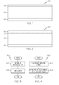
- FIG. 1 is a cross-sectional view of a noise suppression panel in accordance with an exemplary embodiment
- FIG. 2 is a cross-sectionl view of a noise suppression panel in accordance with another exemplary embodiment
- FIG. 3 is a method for treating the noise suppression panels of FIGs. 1 and 2 with a fluid repellent in accordance with an exemplary embodiment
- FIG. 4 is a method for treating the exemplary noise suppression panels of FIGs. 1 and 2 with a fluid repellent in accordance with another exemplary embodiment.
- the panel 100 includes a face plate 102, a back plate 103, and a bulk absorber 104.
- the face plate 102 is preferably perforated to a desired percent open area (POA) value and may be constructed from any one of numerous types of materials to provide structural integrity to the panel 100. Some suitable materials include, but are not limited to, stainless steel and carbon composites. In one exemplary embodiment, the face plate 102 is constructed of stainless steel.
- relatively low POA values e.g., ⁇ 5%
- relatively high POA values e.g., ⁇ 30%) provide acoustic transparency
- the face plate 102 is perforated to a POA value greater than 30% to ensure acoustic transparency to any incident sound.
- the back plate 103 is preferably imperforate and is constructed of any one of numerous types of non-porous materials such as, for example, aluminum, epoxy, or bismaleimide (BMI).
- the bulk absorber 104 is disposed between the face plate 102 and the back plate 103 and is configured to absorb noise.
- the bulk absorber 104 may be any one of numerous types of suitable noise-reducing materials.
- the bulk absorber 104 is a needle-punched fiber mat.
- the fiber mat may be made of carbon fibers, and may be available through Zoltek Companies, Inc. of St. Louis, Missouri.
- the fiber mat may alternatively be made of volcanic basalt-based materials, such as Sudaglass® available through Sudaglass Fiber Technology, Inc. of Houston, Texas.
- the bulk absorber 104 is made up of a fiber-based acoustic treatment material.
- the material may be a random network of reinforcement microfibers and fibrillated microfibers loosely held together by a polymer binder.
- the bulk absorber 104 preferably has a volume fraction solids of between about 1.5% and about 5.5%, and more preferably about 4%.
- the reinforcement microfibers and fibrillated microfibers are included in the bulk absorber 104 at a 1:1 to 15:1 ratio, by weight.
- the binder is included at approximately a 0.20:1 ratio to about a 1.5:1 ratio, by weight, to the microfibers. Consequently, the bulk absorber 104 includes between about 3% and about 25% by weight of fibrillated microfibers, between about 20% and about 75% by weight of reinforcement microfibers, and between about 15% and about 60% by weight of the binder.
- the reinforcement microfibers are relatively stiff, smooth, and linear fibers that are capable of absorbing noise. Any one of numerous suitable acoustic-reducing microfibers may be employed.
- the reinforcement microfibers include carbon, and may be, for example polyacrylonitrile (PAN) based carbon fibers such as Thornel® T-300 PAN sold by Cytec Industries Inc. of West Paterson, NJ.
- PAN polyacrylonitrile
- basalt microfibers are used.
- One exemplary basalt microfiber that may be used is provided under the tradename Sudaglass® and is available through Sudaglass Fiber Technology, Inc. of Houston, Texas.
- the fibrillated microfibers enable forming a network with the reinforcement fibers where the fibers have no preferred orientation.
- the fibrillated microfibers are highly branched and are capable of intertwining with the linear reinforcing microfibers to form a fluffy mass with the 1.5-5.5% volume fraction solids mentioned above.
- Several fibrillated microfibers may be suitably employed.
- the fibrillated microfibers are fibrillated aramid microfibers.
- the fibrillated aramid microfibers also known in the art as fibrillated poly(aromatic amide) microfibers are capable of maintaining integrity at temperatures of at least 280°C and are available from E.I. DuPont de Nemours of Delaware under the tradename Kevlar® pulp.
- Another suitable fibrillated microfiber is, as an example, acrylic pulp.
- the binder which may be, for example, a polymer
- the polymer binder may be any one of numerous suitable materials that can hold the microfibers together but does not significantly decrease the size of the openings in the random microfiber network.
- Suitable thermoset polymer binders include, but are not limited to polymeric resins and powdered phenolic binders, such as Durite® binders AD- 3239 or AD-5614 available through Hexion Specialty Chemicals of Columbus, OH, Thermoplastic powder binders, such as those that include polyvinyl chloride and polyethylene, may alternatively be used.
- the bulk absorber 104 may include a fluid repellent.
- the fluid repellent is at least partially made up of a material having a surface energy of less than about 15 erg/cm 2 .
- Such materials are generally known in the art as "low surface energy materials".
- the fiber mat or the fiber-based acoustic treatment material is dipped in a liquid-form of a low surface energy material, such as a fluoropolymer.
- the low surface energy material is sprayed onto the fiber mat or the fiber-based acoustic treatment material.
- an intermediate layer 106 may be included, as shown in FIG. 2 .
- the intermediate layer 106 is disposed between the face plate 102 and the bulk absorber 104 and is included to provide fluid repellency.
- the intermediate layer 106 may be made of any one of numerous fluid repelling materials.
- the intermediate layer 106 may be made of polyetheretherketone or a fluoropolymer, such as Teflon® available through E.I. DuPont de Nemours of Delaware.
- the intermediate layer 106 may be a fine screen or mesh, such as between about a 40x40 mesh and a 120x120 mesh, of a metallic material, such as aluminum. The mesh may be coated or treated with a low surface energy coating, such as a fluoropolymer. Suitable fluoropolymers include, but are not limited to, Fluorepel TM 501PF available through Cytonix Corporation of Beltsville, MD.
- the panel 100 may be further treated to include a fluid repellent.
- a fluid repellent For example, outer surfaces of the panel 100 may be coated, sprayed, or infused with the fluid repellent.
- the fluid repellent may be a low surface energy coating, such as a fluoropolymer, and may not be similar to that used to treat the bulk absorber 104.
- the fluid repellent is a particle coating on the panel 100 that includes micron or submicron size hydrophobic particles, which are optionally held in place by a binder. The particles may be fumed silica and the binder may be a phenolic resin or an adhesive.
- Suitable binders include rubber-to-metal bonding adhesives, such as a Chemlok® adhesive available through the Lord Corporation of Cary, NC, high temperature binders such as those from ZYP Coatings, Inc. of Oak Ridge, NT, or polysilazane resins, such as those available from KiON Corporation of Willow Grove, PA.
- the particle coatings exhibit excellent hydrophobic characteristics and are generally more resistant to elevated temperatures than chemical based low surface energy materials such as fluorocarbons.
- Another class of low surface energy coatings is polysilazane clear coats.
- One suitable polysilazane clear coat includes KiON® Anti-Graffiti Clear Coat from KiON Corporation in Willow Grove, PA.
- the particle coatings may include a fluoropolymer coating for enhanced effectiveness in rejecting organic based liquids, such as jet fuel.
- FIG. 3 One exemplary method 300 by which the panel 100 may be treated with the fluid repellent is shown in FIG. 3 .
- a metal surface of the panel is dipped into a reactive solution to form a coating, step 302.
- Dip coating may occur by dipping the panel 100 into a solution including particles and alcohol.
- the solution includes about 5% by weight of phenolic powder, about 5% by weight of fumed silica, and 90% by weight of isopropyl alcohol.
- the solution coating the panel 100 is then cured, step 304.
- the panel 100 is treated by being subjected to a plasma vapor deposition process 400.
- the panel 100 is placed in a deposition chamber, step 402.
- the panel 100 may include the face plate 102 and bulk absorber 104, or the face plate 102, bulk absorber 104, and the intermediate layer 106.
- the panel 100 is exposed to a plasma chemical vapor deposition process, step 404.
- the plasma chemical vapor deposition process is preferably a low pressure, low temperature process, for example having a pressure of less than about 20 milliTorr and a temperature of less than about 40°C.
- One vendor of plasma deposition processes is P2i of Abington, Oxfordshire, UK.
- a low surface energy material is introduced into the deposition chamber as plasma, causing the low surface energy coating to penetrate the panel 100 and to bond in a thin layer to the surface.
- Any one of numerous low surface energy coatings may be used, such as, for example, fluoropolymers including perfluoroacrylate.
- the low surface energy coating employed in this process 400 may or may not have a similar composition to that of the panel component low surface energy coating.
- this process 400 is described as being applied to the panel 100, it will be appreciated that it may be applied to one or more components of the panel 100, such as to the face plate 102, back plate 103, bulk absorber 104, or the intermediate layer 106.
- the noise suppression panel may be more effective in repelling fluids as compared to known materials. Additionally, the noise suppression panel may be relatively inexpensive to manufacture and may remain effective over a relatively wide frequency range. Moreover, in embodiments that include the combination of the reinforcement microfibers with the fibrillated microfibers, the panel may have an average sound absorption coefficient that is about 32% higher than a known high quality noise-reducing foam.
Landscapes
- Engineering & Computer Science (AREA)
- Chemical & Material Sciences (AREA)
- Combustion & Propulsion (AREA)
- Mechanical Engineering (AREA)
- General Engineering & Computer Science (AREA)
- Physics & Mathematics (AREA)
- Acoustics & Sound (AREA)
- Multimedia (AREA)
- Soundproofing, Sound Blocking, And Sound Damping (AREA)
Abstract
Description
- The inventive subject matter relates to noise suppression panels and, more particularly, to noise suppression panels for use in aircraft ducts and plenums, and methods of making the panels.
- Many aircraft are powered by jet engines. In most instances, jet engines include one or more gas-powered turbine engines, auxiliary power units (APUs), and/or environmental control systems (ECSs), which can generate both thrust to propel the aircraft and electrical energy to power systems installed in the aircraft. Although most aircraft engines are generally safe, reliable, and efficient, the engines do exhibit certain drawbacks. For example, the turbine engines, as well as other components that make up the engine, can be sources of unwanted noise, especially during aircraft take-off and landing operations. Moreover, APUs and ECSs can be sources of unwanted ramp noise. Thus, various governmental rules and regulations aimed at mitigating such noise sources have been enacted.
- To address, and at least somewhat alleviate, the unwanted noise emanating from aircraft noise sources, and to thereby comply with the above-noted rules and regulations, various types of noise reduction treatments have been developed. For example, one type of noise reduction treatment that has been developed for use in aircraft ducts is a noise suppression panel. In many instances, noise suppression panels are flat or contoured, and include either a bulk noise suppression material or a honeycomb structure disposed between a backing plate and a face plate. The noise suppression panels may be placed on the interior surface of engine or APU inlet and/or outlet plenums to reduce noise emanations.
- Although the above-described noise suppression panels do exhibit fairly good noise suppression characteristics, the panels also exhibit certain drawbacks. For example, if the noise suppression panels are exposed to and retain fluids, the noise suppression characteristics of the panels may diminish. As a result, the panels may become ineffective. Additionally, if the bulk noise suppression material disposed within the panels is exposed to certain fluids, it may become degraded.
- Hence, there is a need for a noise suppression panel that rejects or repels fluids and/or remains operable when exposed to fluids. It is further desired for the panel to be relatively inexpensive and easy to manufacture. The inventive subject matter addresses one or more of these needs.
- The inventive subject matter provides noise suppression panels with fluid rejection capability and methods of making the panels.
- In one embodiment, and by way of example only, the noise suppression panel with fluid rejection capability includes a face plate, a back plate, a bulk absorber, and a fluid repellent. The face plate includes a perforated material. The bulk absorber is disposed between the face plate and the back plate. The fluid repellent is disposed on at least a portion of the face plate or the bulk absorber.
- In another embodiment, and by way of example only, the noise suppression panel with fluid rejection capability includes a face plate, a back plate, a bulk absorber, and a fluid repellent. The face plate includes a perforated material having a percent open area value that is greater than about 30%. The bulk absorber is disposed between the face plate and the back plate and includes between about 3% and about 25% by weight of fibrillated microfibers, between about 20% and about 75% by weight of reinforcement microfibers, and between about 15% and about 60% by weight of a binder. The fluid repellent is disposed on at least a portion of the face plate or the bulk absorber.
- In still another embodiment, and by way of example only, a method of manufacturing a noise suppression panel with fluid rejection capability is provided that includes forming a noise suppression panel, where the panel includes a face plate including a perforated material having a percent open area value that is greater than about 30%, a back plate, and a bulk absorber disposed between the face plate and the back plate. A first low surface energy coating is then deposited on at least a portion of the panel via a plasma chemical vapor deposition process.
- Other independent features and advantages of the preferred panel and methods of manufacturing the panel will become apparent from the following detailed description, taken in conjunction with the accompanying drawings which illustrate, by way of example, the principles of the inventive subject matter.
-
FIG. 1 is a cross-sectional view of a noise suppression panel in accordance with an exemplary embodiment; -
FIG. 2 is a cross-sectionl view of a noise suppression panel in accordance with another exemplary embodiment; -
FIG. 3 is a method for treating the noise suppression panels ofFIGs. 1 and 2 with a fluid repellent in accordance with an exemplary embodiment; and -
FIG. 4 is a method for treating the exemplary noise suppression panels ofFIGs. 1 and 2 with a fluid repellent in accordance with another exemplary embodiment. - Before proceeding with the detailed description, it is to be appreciated that the described embodiment is not limited to use in conjunction with a particular type of engine or in a particular type of vehicle. Thus, although the present embodiment is, for convenience of explanation, described as being implemented in an aircraft environment, it will be appreciated that it can be implemented in various other types of vehicles, and in various other systems and environments.
- Turning now to the description and with reference first to
FIG. 1 , an exemplary hydrophobicnoise suppression panel 100 is depicted in cross section. Thepanel 100 includes aface plate 102, aback plate 103, and abulk absorber 104. Theface plate 102 is preferably perforated to a desired percent open area (POA) value and may be constructed from any one of numerous types of materials to provide structural integrity to thepanel 100. Some suitable materials include, but are not limited to, stainless steel and carbon composites. In one exemplary embodiment, theface plate 102 is constructed of stainless steel. As is generally known, relatively low POA values (e.g., ~5%) provide acoustic resistance, whereas relatively high POA values (e.g., ~30%) provide acoustic transparency. In a particular exemplary embodiment, theface plate 102 is perforated to a POA value greater than 30% to ensure acoustic transparency to any incident sound. Theback plate 103 is preferably imperforate and is constructed of any one of numerous types of non-porous materials such as, for example, aluminum, epoxy, or bismaleimide (BMI). - The
bulk absorber 104 is disposed between theface plate 102 and theback plate 103 and is configured to absorb noise. In this regard, the bulk absorber 104 may be any one of numerous types of suitable noise-reducing materials. In one exemplary embodiment, thebulk absorber 104 is a needle-punched fiber mat. The fiber mat may be made of carbon fibers, and may be available through Zoltek Companies, Inc. of St. Louis, Missouri. The fiber mat may alternatively be made of volcanic basalt-based materials, such as Sudaglass® available through Sudaglass Fiber Technology, Inc. of Houston, Texas. - In another exemplary embodiment, the
bulk absorber 104 is made up of a fiber-based acoustic treatment material. The material may be a random network of reinforcement microfibers and fibrillated microfibers loosely held together by a polymer binder. The bulk absorber 104 preferably has a volume fraction solids of between about 1.5% and about 5.5%, and more preferably about 4%. The reinforcement microfibers and fibrillated microfibers are included in the bulk absorber 104 at a 1:1 to 15:1 ratio, by weight. The binder is included at approximately a 0.20:1 ratio to about a 1.5:1 ratio, by weight, to the microfibers. Consequently, the bulk absorber 104 includes between about 3% and about 25% by weight of fibrillated microfibers, between about 20% and about 75% by weight of reinforcement microfibers, and between about 15% and about 60% by weight of the binder. - The reinforcement microfibers are relatively stiff, smooth, and linear fibers that are capable of absorbing noise. Any one of numerous suitable acoustic-reducing microfibers may be employed. In one exemplary embodiment, the reinforcement microfibers include carbon, and may be, for example polyacrylonitrile (PAN) based carbon fibers such as Thornel® T-300 PAN sold by Cytec Industries Inc. of West Paterson, NJ. In another exemplary embodiment, basalt microfibers are used. One exemplary basalt microfiber that may be used is provided under the tradename Sudaglass® and is available through Sudaglass Fiber Technology, Inc. of Houston, Texas.
- The fibrillated microfibers enable forming a network with the reinforcement fibers where the fibers have no preferred orientation. In this regard, the fibrillated microfibers are highly branched and are capable of intertwining with the linear reinforcing microfibers to form a fluffy mass with the 1.5-5.5% volume fraction solids mentioned above. Several fibrillated microfibers may be suitably employed. In one exemplary embodiment, the fibrillated microfibers are fibrillated aramid microfibers. The fibrillated aramid microfibers, also known in the art as fibrillated poly(aromatic amide) microfibers are capable of maintaining integrity at temperatures of at least 280°C and are available from E.I. DuPont de Nemours of Delaware under the tradename Kevlar® pulp. Another suitable fibrillated microfiber is, as an example, acrylic pulp.
- To provide the random microfiber network with sufficient mechanical integrity for disposal in the
panel 100, the binder, which may be, for example, a polymer, is included. The polymer binder may be any one of numerous suitable materials that can hold the microfibers together but does not significantly decrease the size of the openings in the random microfiber network. Suitable thermoset polymer binders include, but are not limited to polymeric resins and powdered phenolic binders, such as Durite® binders AD- 3239 or AD-5614 available through Hexion Specialty Chemicals of Columbus, OH, Thermoplastic powder binders, such as those that include polyvinyl chloride and polyethylene, may alternatively be used. - No matter the particular material, the
bulk absorber 104 may include a fluid repellent. The fluid repellent is at least partially made up of a material having a surface energy of less than about 15 erg/cm2. Such materials are generally known in the art as "low surface energy materials". In one exemplary embodiment, the fiber mat or the fiber-based acoustic treatment material is dipped in a liquid-form of a low surface energy material, such as a fluoropolymer. In another exemplary embodiment, the low surface energy material is sprayed onto the fiber mat or the fiber-based acoustic treatment material. - In some embodiments, an intermediate layer 106 may be included, as shown in
FIG. 2 . In such an embodiment, the intermediate layer 106 is disposed between theface plate 102 and thebulk absorber 104 and is included to provide fluid repellency. In this regard, the intermediate layer 106 may be made of any one of numerous fluid repelling materials. For example, the intermediate layer 106 may be made of polyetheretherketone or a fluoropolymer, such as Teflon® available through E.I. DuPont de Nemours of Delaware. In other embodiments, the intermediate layer 106 may be a fine screen or mesh, such as between about a 40x40 mesh and a 120x120 mesh, of a metallic material, such as aluminum. The mesh may be coated or treated with a low surface energy coating, such as a fluoropolymer. Suitable fluoropolymers include, but are not limited to, Fluorepel™ 501PF available through Cytonix Corporation of Beltsville, MD. - In another exemplary embodiment, the
panel 100 may be further treated to include a fluid repellent. For example, outer surfaces of thepanel 100 may be coated, sprayed, or infused with the fluid repellent. The fluid repellent may be a low surface energy coating, such as a fluoropolymer, and may not be similar to that used to treat thebulk absorber 104.
In one exemplary embodiment, the fluid repellent is a particle coating on thepanel 100 that includes micron or submicron size hydrophobic particles, which are optionally held in place by a binder. The particles may be fumed silica and the binder may be a phenolic resin or an adhesive. Suitable binders include rubber-to-metal bonding adhesives, such as a Chemlok® adhesive available through the Lord Corporation of Cary, NC, high temperature binders such as those from ZYP Coatings, Inc. of Oak Ridge, NT, or polysilazane resins, such as those available from KiON Corporation of Willow Grove, PA. The particle coatings exhibit excellent hydrophobic characteristics and are generally more resistant to elevated temperatures than chemical based low surface energy materials such as fluorocarbons. Another class of low surface energy coatings is polysilazane clear coats. One suitable polysilazane clear coat includes KiON® Anti-Graffiti Clear Coat from KiON Corporation in Willow Grove, PA. The particle coatings may include a fluoropolymer coating for enhanced effectiveness in rejecting organic based liquids, such as jet fuel. - One
exemplary method 300 by which thepanel 100 may be treated with the fluid repellent is shown inFIG. 3 . Here, a metal surface of the panel is dipped into a reactive solution to form a coating,step 302. Dip coating may occur by dipping thepanel 100 into a solution including particles and alcohol. In one exemplary embodiment, the solution includes about 5% by weight of phenolic powder, about 5% by weight of fumed silica, and 90% by weight of isopropyl alcohol. The solution coating thepanel 100 is then cured,step 304. - In another
exemplary method 400 shown inFIG. 4 , thepanel 100 is treated by being subjected to a plasmavapor deposition process 400. First, thepanel 100 is placed in a deposition chamber,step 402. Thepanel 100 may include theface plate 102 andbulk absorber 104, or theface plate 102,bulk absorber 104, and the intermediate layer 106. Next, thepanel 100 is exposed to a plasma chemical vapor deposition process, step 404. The plasma chemical vapor deposition process is preferably a low pressure, low temperature process, for example having a pressure of less than about 20 milliTorr and a temperature of less than about 40°C. One vendor of plasma deposition processes is P2i of Abington, Oxfordshire, UK. A low surface energy material is introduced into the deposition chamber as plasma, causing the low surface energy coating to penetrate thepanel 100 and to bond in a thin layer to the surface. Any one of numerous low surface energy coatings may be used, such as, for example, fluoropolymers including perfluoroacrylate. Additionally, in embodiments in which one or more of the panel components includes a low surface energy coating, the low surface energy coating employed in thisprocess 400 may or may not have a similar composition to that of the panel component low surface energy coating. Moreover, although thisprocess 400 is described as being applied to thepanel 100, it will be appreciated that it may be applied to one or more components of thepanel 100, such as to theface plate 102, backplate 103,bulk absorber 104, or the intermediate layer 106. - There has now been provided a noise suppression panel that may be more effective in repelling fluids as compared to known materials. Additionally, the noise suppression panel may be relatively inexpensive to manufacture and may remain effective over a relatively wide frequency range. Moreover, in embodiments that include the combination of the reinforcement microfibers with the fibrillated microfibers, the panel may have an average sound absorption coefficient that is about 32% higher than a known high quality noise-reducing foam.
- While the inventive subject matter has been described with reference to a preferred embodiment, it will be understood by those skilled in the art that various changes may be made and equivalents may be substituted for elements thereof without departing from the scope of the inventive subject matter. In addition, many modifications may be made to adapt to a particular situation or material to the teachings of the inventive subject matter without departing from the essential scope thereof. Therefore, it is intended that the inventive subject matter not be limited to the particular embodiment disclosed as the best mode contemplated for carrying out this inventive subject matter, but that the inventive subject matter will include all embodiments falling within the scope of the appended claims.
Claims (10)
- A noise suppression panel (100) with fluid rejection capability comprising:a face plate (102) comprising a perforated material;a back plate (103);a bulk absorber (104) disposed between the face plate (102) and the back plate (103); anda fluid repellent disposed on at least a portion of the face plate (102), the back plate (103), or the bulk absorber (104).
- The panel (100) of claim 1, wherein the bulk absorber comprises:between about 3% and about 25% by weight of fibrillated microfibers;between about 20% and about 75% by weight of reinforcement microfibers; andbetween about 15% and about 60% by weight of a binder.
- The panel (100) of claim 2, wherein the reinforcement microfibers comprise carbon fibers.
- The panel (100) of claim 2, wherein the reinforcement microfibers comprise basalt fibers.
- The panel (100) of claim 2, wherein the material is configured to have a volume fraction solids of between about 1.5% and about 5.5%.
- The panel (100) of claim 1, wherein the bulk absorber comprises a needle-punched mat.
- The panel (100) of claim 1, wherein the fluid repellent comprises a coating having a surface energy of less than about 15 erg/cm2.
- The panel (100) of claim 7, wherein the coating comprises a fluoropolymer.
- The panel (100) of claim 1, wherein the fluid repellent treatment comprises an intermediate layer (106) disposed between the face plate (102) and the bulk absorber (104), and the intermediate layer (106) comprises a material selected from the group consisting of a metallic mesh, a polyetheretherketone woven fabric, and a fluoropolymer woven fabric.
- The panel (100) of claim 1, wherein the fluid repellent comprises a coating comprising particles held in place by a binder.
Applications Claiming Priority (1)
| Application Number | Priority Date | Filing Date | Title |
|---|---|---|---|
| US63983206A | 2006-12-14 | 2006-12-14 |
Publications (1)
| Publication Number | Publication Date |
|---|---|
| EP1932659A1 true EP1932659A1 (en) | 2008-06-18 |
Family
ID=39166695
Family Applications (1)
| Application Number | Title | Priority Date | Filing Date |
|---|---|---|---|
| EP07122568A Withdrawn EP1932659A1 (en) | 2006-12-14 | 2007-12-06 | Noise suppression panel with fluid rejection capability and methods of making the same |
Country Status (1)
| Country | Link |
|---|---|
| EP (1) | EP1932659A1 (en) |
Cited By (3)
| Publication number | Priority date | Publication date | Assignee | Title |
|---|---|---|---|---|
| FR2934641A1 (en) * | 2008-07-30 | 2010-02-05 | Aircelle Sa | Sound attenuation panel for jet engine nacelle of aircraft, has porous material placed on structuring skin that is fixed with stiffener, where porous material is used as sound absorption material |
| EP2327883A3 (en) * | 2009-11-28 | 2013-12-11 | Robert Bosch GmbH | Hydraulic assembly with multi-layer acoustic dampening/reducing cover |
| US11391244B2 (en) | 2019-01-04 | 2022-07-19 | Rohr, Inc. | Acoustic liner and method of forming an acoustic liner |
Citations (4)
| Publication number | Priority date | Publication date | Assignee | Title |
|---|---|---|---|---|
| US4130175A (en) * | 1977-03-21 | 1978-12-19 | General Electric Company | Fluid-impervious acoustic suppression panel |
| JPS5514835B2 (en) * | 1975-06-13 | 1980-04-18 | ||
| US4441578A (en) * | 1981-02-02 | 1984-04-10 | Rohr Industries, Inc. | Encapsulated bulk absorber acoustic treatments for aircraft engine application |
| US4848514A (en) * | 1987-10-06 | 1989-07-18 | Uas Support, Inc. | Sound attenuation system for jet aircraft engines |
-
2007
- 2007-12-06 EP EP07122568A patent/EP1932659A1/en not_active Withdrawn
Patent Citations (4)
| Publication number | Priority date | Publication date | Assignee | Title |
|---|---|---|---|---|
| JPS5514835B2 (en) * | 1975-06-13 | 1980-04-18 | ||
| US4130175A (en) * | 1977-03-21 | 1978-12-19 | General Electric Company | Fluid-impervious acoustic suppression panel |
| US4441578A (en) * | 1981-02-02 | 1984-04-10 | Rohr Industries, Inc. | Encapsulated bulk absorber acoustic treatments for aircraft engine application |
| US4848514A (en) * | 1987-10-06 | 1989-07-18 | Uas Support, Inc. | Sound attenuation system for jet aircraft engines |
Non-Patent Citations (1)
| Title |
|---|
| DATABASE WPI Week 198020, Derwent World Patents Index; AN 1980-35822C, XP002473268 * |
Cited By (4)
| Publication number | Priority date | Publication date | Assignee | Title |
|---|---|---|---|---|
| FR2934641A1 (en) * | 2008-07-30 | 2010-02-05 | Aircelle Sa | Sound attenuation panel for jet engine nacelle of aircraft, has porous material placed on structuring skin that is fixed with stiffener, where porous material is used as sound absorption material |
| EP2327883A3 (en) * | 2009-11-28 | 2013-12-11 | Robert Bosch GmbH | Hydraulic assembly with multi-layer acoustic dampening/reducing cover |
| US11391244B2 (en) | 2019-01-04 | 2022-07-19 | Rohr, Inc. | Acoustic liner and method of forming an acoustic liner |
| US11808235B2 (en) | 2019-01-04 | 2023-11-07 | Rohr, Inc. | Acoustic liner and method of forming an acoustic liner |
Similar Documents
| Publication | Publication Date | Title |
|---|---|---|
| CN102905888B (en) | Give the method for material conductivity used in composite article manufacture and material thereof | |
| KR102507982B1 (en) | Acoustic prepregs, cores and composite articles and methods of use thereof | |
| Jang et al. | Impact resistance and energy absorption mechanisms in hybrid composites | |
| US4581284A (en) | Fiber compound material | |
| US5315820A (en) | Composite structural component | |
| US7832983B2 (en) | Nacelles and nacelle components containing nanoreinforced carbon fiber composite material | |
| KR101114805B1 (en) | Sound absorbing material | |
| EP3247556B1 (en) | Sound absorption materials based on nonwovens | |
| US20050136761A1 (en) | Fire-Retardant Composite Material | |
| JP2006525147A (en) | Structural composites for sound attenuation | |
| US10245804B2 (en) | Fire retarded aramid fiber-based honeycomb | |
| CN101797804A (en) | Membrane structure for vacuum assisted molding fiber reinforced article | |
| EP3488120A1 (en) | Vibration damping system | |
| WO2016131035A1 (en) | Nonwoven infrared reflective fiber materials | |
| US11351752B2 (en) | Thermal/acoustical liner | |
| WO1994026994A1 (en) | Acoustic attenuating liner and method of making same | |
| US7955698B2 (en) | Fiber-based acoustic treatment material and methods of making the same | |
| US20110169182A1 (en) | Methods of forming bulk absorbers | |
| KR20170124373A (en) | Bulletproof module for automotive comprising aramid fiber and method for manufacturing thereof | |
| Wyerman | New frontiers for fiber based noise control solutions | |
| WO2020225397A1 (en) | Noise-attenuating device and method of manufacture | |
| JP2016204573A (en) | COMPOSITE AND MANUFACTURING METHOD THEREOF AND FLUID CONTROL DEVICE COMPRISING THE COMPOSITE |
Legal Events
| Date | Code | Title | Description |
|---|---|---|---|
| PUAI | Public reference made under article 153(3) epc to a published international application that has entered the european phase |
Free format text: ORIGINAL CODE: 0009012 |
|
| 17P | Request for examination filed |
Effective date: 20071206 |
|
| AK | Designated contracting states |
Kind code of ref document: A1 Designated state(s): AT BE BG CH CY CZ DE DK EE ES FI FR GB GR HU IE IS IT LI LT LU LV MC MT NL PL PT RO SE SI SK TR |
|
| AX | Request for extension of the european patent |
Extension state: AL BA HR MK RS |
|
| 17Q | First examination report despatched |
Effective date: 20080724 |
|
| AKX | Designation fees paid |
Designated state(s): DE FR |
|
| GRAP | Despatch of communication of intention to grant a patent |
Free format text: ORIGINAL CODE: EPIDOSNIGR1 |
|
| STAA | Information on the status of an ep patent application or granted ep patent |
Free format text: STATUS: THE APPLICATION IS DEEMED TO BE WITHDRAWN |
|
| 18D | Application deemed to be withdrawn |
Effective date: 20091229 |