EP1932420A1 - Sieve support structure for an agricultural combine - Google Patents
Sieve support structure for an agricultural combine Download PDFInfo
- Publication number
- EP1932420A1 EP1932420A1 EP07122780A EP07122780A EP1932420A1 EP 1932420 A1 EP1932420 A1 EP 1932420A1 EP 07122780 A EP07122780 A EP 07122780A EP 07122780 A EP07122780 A EP 07122780A EP 1932420 A1 EP1932420 A1 EP 1932420A1
- Authority
- EP
- European Patent Office
- Prior art keywords
- support structure
- sieve
- rails
- rail
- rail assembly
- Prior art date
- Legal status (The legal status is an assumption and is not a legal conclusion. Google has not performed a legal analysis and makes no representation as to the accuracy of the status listed.)
- Granted
Links
Images




Classifications
-
- A—HUMAN NECESSITIES
- A01—AGRICULTURE; FORESTRY; ANIMAL HUSBANDRY; HUNTING; TRAPPING; FISHING
- A01F—PROCESSING OF HARVESTED PRODUCE; HAY OR STRAW PRESSES; DEVICES FOR STORING AGRICULTURAL OR HORTICULTURAL PRODUCE
- A01F12/00—Parts or details of threshing apparatus
- A01F12/44—Grain cleaners; Grain separators
- A01F12/446—Sieving means
Definitions
- This invention relates generally to support structure for a grain cleaning sieve or sieves of a cleaning system of an agricultural combine, and more particularly, to a sieve support structure which is configured and adapted for resisting loading conditions, particularly unevenly distributed or offset loading conditions, which can exert stresses and strains on the structure urging deformation thereof such as racking or parallelogramming, and also possible resultant cracking thereof, for improving the structural life of the support structure and the sieve.
- the cleaning system will consist of two sieves, an upper or coarser sieve or chaffer located below the threshing mechanism or separator of the combine and having larger sieve openings for the passage of grain and smaller pieces of plant material therethrough but relatively little of the larger chaff, and a lower finer sieve located below the chaffer for receiving the grain and smaller pieces of plant material therefrom and having smaller sieve openings for passage of the grain therethrough but relatively little of the plant material.
- a flow of air is directed upwardly therethrough for facilitating lifting and carrying away of lighter elements of the plant material from the upper surfaces of the sieves.
- a typical sieve construction as described for instance in US-A-4,712,568 , has an overall generally rectangular shape and includes a plurality of elongate parallel, pivotally mounted, sidewardly extending slats, each slat including a plurality of longitudinally spaced upwardly extending inclined fingers, the slats being pivotable through a range of open positions angularly oriented to horizontal for providing a corresponding range of openings or spaces between the fingers of adjacent ones of the slats.
- a typical sieve includes an adjusting member which contacts each of the slats, and a linkage and/or cable arrangement connected between the adjusting member and one or more manually or automatically movable adjusting elements or adjustors, in the latter instance, which can be moved by an actuator driven by an electrical, fluid, or other controller for moving the linkage or cable arrangement and member and thus changing the angular orientation of the slats and as a result, the opening size.
- the sieves are typically each supported by a correspondingly rectangular shaped welded or fastened assembly commonly known as a cleaning shoe or sieve rail assembly.
- the sieve rail assemblies are typically supported for rapid reciprocating movement in the fore and aft direction, as driven by a suitable drive element or actuator, such as a powered crank mechanism or the like.
- a suitable drive element or actuator such as a powered crank mechanism or the like.
- the drive is connected in driving relation to the rail assembly supporting the upper sieve or chaffer, which upper rail assembly supports the rail assembly supporting the lower sieve for reciprocating movement opposite to reciprocating movement of the upper sieve. That is, as the upper sieve is driven in one direction, the lower sieve is driven by the upper sieve in the opposite direction.
- grain, and plant and other material other than grain will sometimes be deposited on the upper one of the sieves by the threshing mechanism in an uneven manner, particularly as the combine is traversing a hillside, so as to result in uneven loading conditions exerted against both the sieve and the sieve rail assemblies.
- Air flow upwardly through the sieve may also be uneven.
- the sieves and particularly the sieve rail assemblies are subjected to uneven stress conditions which can cause deformation thereof, particularly racking or parallelogramming of the rectangular shapes, which is a condition wherein the applied forces urge the rail assembly from its normal rectangular shape.
- this has been found to result in the development of fatigue cracks in the structural elements of the sieve rail assemblies, particularly, in the corners thereof, which are typically welded joints.
- the occurrence and/or extent of these conditions have been found to be greater in sieves of larger size, either in length, width, or both, which are used in larger combines, due to the greater crop loads processed by the sieves.
- a sieve support structure for installation in an agricultural harvesting machine, said support structure comprising:
- the elongate tension members In opposition to loading conditions urging deformation such as racking and/or parallelogramming of the assembly, the elongate tension members extend generally diagonally through the rectangular space and have opposite end portions connected to the first and second rails, respectively.
- the tension members are tensioned so as to simultaneously urge the rails against the compression members so as to apply a compression load thereagainst sufficient to at least substantially resist the applied loads urging the assembly from its original shape.
- the elongate compressed cross members are pivotally connected to and extending between the first and second rails at longitudinally spaced locations therealong, respectively.
- the rail assembly is forceably maintained and held in its desired rectangular shape in opposition to forces and other applied loads urging deformation thereof, such as commonly present in the cleaning system environment, and, any deformation such as parallelogramming or racking of the rail assembly will be accommodated by the pivotal connection between the rails and compression members, such that cracking is avoided.
- the rails of the rail assembly are supported along opposite sides of an interior cavity of a combine, and are driven reciprocatingly longitudinally by a suitable actuator, which can include, for instance, a crank mechanism, eccentric drive, or the like.
- a suitable actuator can include, for instance, a crank mechanism, eccentric drive, or the like.
- a threshing system of the combine located above the cleaning system, can, from time to time, discharge threshed crop material onto a sieve supported by the rail assembly in an uneven manner, particularly, more toward one side, such that the side carrying the greater amount of crop material will have greater momentum compared to the other side, such that the rail assembly is subjected to forces tending to deform it from its desired original rectangular shape, typically toward a more parallelogram shape.
- Forces urging the rail assembly from its original shape can also be generated by bending and/or twisting of structural components of the combine resulting from loading conditions exerted thereagainst, such as can be generated when the combine traverses rough terrain, hillsides and the like. These loading conditions will be resisted by the combination of the tension of the tension members and resulting compression of the compression members. Any deformation such as racking or parallelogramming of the rail assembly which does result, will be limited, and will not be as likely to damage the rail assembly, as the pivotal connections between the rails and the compression members will accommodate the deformation by allowing deviation from the normal 90° angle between the joined members. And, when the forces and/or loading conditions acting to urge the structural elements of the rail assembly from its original shape are removed or diminished, the tension members will operate to return them to their original 90° position.
- a conventional agricultural combine 20 is shown, illustrating generally the location of sieve support structure 22 for supporting an upper sieve 24 and a lower sieve 26 of a cleaning system 28 of combine 20.
- Agricultural combine 20 generally includes a threshing mechanism or separator 30 operable for receiving crop material from a harvesting mechanism (not shown) on a front end 32 of combine 20, separator 30 being operable for separating smaller grains, seeds, pods and related plant material from larger stalks, stems, leaves, husks and other elements of the crop material, as well as vines, weeds and the like which may be present in the harvested crop material.
- the smaller material falls from separator 30, either directly or indirectly, to cleaning system 28, as generally illustrated by arrows A.
- Cleaning system 28 includes a fan 34 disposed forwardly of and just below upper and lower sieves 24 and 26, and operable for directing a flow of air, denoted by arrow B, upwardly and rearwardly through sieves 24 and 26.
- sieves 24 and 26 are moved reciprocatingly forwardly and rearwardly, as denoted by arrows C ( Figures 1 , 2 , 3 and 9 ), for cleaning pod fragments and other MOG from the grain, the grain falling through sieves 24 and 26 for collection, and the MOG being blown rearwardly from the cleaning system and rearwardly from the combine, or to a tailings system, if provided, in the well-known manner.
- Support structure 36 includes an upper sieve rail assembly 38 supporting upper sieve 24, and a lower sieve rail assembly 40 supporting lower sieve 26.
- Rail assembly 38 and rail assembly 40 each essentially comprises a rectangular structure including parallel, spaced apart side rails 42 and 44, configured for supporting the respective sieve 24 or 26, and connected by transversely extending cross members 46 and 48 which span the space between the rails 42 and 44.
- Each connection between a rail 42 or 44 and a cross member 46 or 48 is a rigid connection, such as by welding.
- upper and lower rail assemblies 38 and 40 will typically be rapidly reciprocatingly moved or vibrated in the forward and rearward directions, as denoted by arrows C, by a suitable actuator, such as actuator 50 illustrated in Figure 9 .
- actuator 50 will be connected in reciprocating driving relation to upper rail assembly 38, and the lower assembly 40 will be suspended from rail assembly 38 by pivoting members, such that rail assemblies 38 and 40, and sieves 24 and 26 supported thereon, will be reciprocatingly moved in opposite directions.
- One or both of the rail assemblies can be driven from just one side, or both sides.
- crop material may be deposited on upper sieve 24 in an uneven manner, particularly, from side to side, as illustrated by the accumulated mass of crop material 52.
- Crop material distribution on lower sieve 24 may also be uneven.
- loads exerted against rail assemblies 38 and 40 during the reciprocating movements can be significantly uneven or unbalanced from side to side, as denoted by the large force arrow F shown disposed more toward one side of sieve 24 in Figure 3 , particularly as the sieve is accelerated, decelerated, and/or the direction of the movement of the sieves and rails is reversed.
- the side of the sieve supporting the mass of crop material 52, and/or any other load or mass distribution that is imbalanced from side to side will have momentum in that direction compared to the other side, which greater mass and momentum will oppose deceleration and change in the direction of movement to a greater extent than the mass and momentum of the other side of the sieve, resulting in exertion of uneven forces on the supporting rail assembly 38 or 40, which forces have been found to cause deformations of the rail assembly, such as the racking and parallelogramming discussed above.
- Another way of looking at this situation is that the centre of gravity of the sieve and material on the sieve will be located more toward one side or the other, and possibly more toward one end or the other, and that this location can vary as conditions change. Such uneven forces have been found to stress and strain the connections between side rails 42, 44 and cross members 46, 48, so as to lead to fatigue cracking of the connections.
- Support structure 22 includes an upper sieve rail assembly 54 supporting upper sieve 24, and a lower sieve rail assembly 56 supporting lower sieve 26.
- Upper sieve rail assembly 54 and lower sieve rail assembly 56 can be of the same construction, or can be different, it being preferred that both of the rail assemblies 54 and 56 include the features of the present invention set forth below for overcoming the problems of the prior art rail assemblies discussed above that can result from contemplated loading conditions to be applied thereagainst, particularly uneven loading conditions, and the resultant problems such as cracking and other damage from stress and strain.
- details of upper sieve rail assembly 54 are described hereinafter, and will be generally representative also of lower rail assembly 56.
- upper sieve rail assembly 54 includes an elongate first rail 58, and an elongate second rail 60 extending substantially parallel to first rail 58.
- Each of rails 58 and 60 is a rigid member, preferably of metal such as steel or aluminium, formed, such as by stamping, into a suitable sectional shape, such as the shape shown.
- rails 58 and 60 will be disposed and supported extending generally forwardly and rearwardly within an interior cleaning cavity or chamber of a combine, such as combine 20, in spaced apart relation generally beside side sheets enclosing the opposite sides of the cleaning cavity.
- Rails 58 and 60 are preferably at least generally mirror images of one another, and each preferably includes a longitudinally extending lip 62 or other structure adapted for engaging and supporting a side edge portion of upper sieve 24.
- Each rail 58 and 60 additionally includes opposite first and second end portions 64 and 66, rails 58 and 60 preferably being oriented such that end portions 64 are located in a rear portion of the combine cleaning region, and end portions 66 located in a more forward portion.
- Rail assembly 54 includes rigid elongate compression members 68 and 70 extending and loaded in compression between rails 58 and 60, preferably between end portions 64 thereof at a rear end of rail assembly 54, and between end portions 66 at the opposite forward end.
- Compression members 68 and 70 are of suitable construction for example, of metal such as steel or aluminium and of a box, channel or L shaped cross section, so as to be sufficiently strong to be capable of withstanding the level of compression loading anticipated to be exerted thereagainst, and material loading conditions, as well as other stresses and strains resulting from externally applied loads, without significant deformation.
- Compression members 68 and 70 each have opposite end portions 72 and 74 suitably configured for pivotal connection to end portions 64 and 66 of rails 58 and 60, which pivotal connections are also to be capable of withstanding the loading conditions anticipated to be exerted thereagainst.
- pivot pins 76 which enable the rails and compression members to be positioned in a desired angular relation one to the other, for instance, a 90° relation as illustrated, so as to impart a preferred generally rectangular overall shape to rail assembly 54, which rectangular shape is adapted for use with rectangular sieves such as upper and lower sieves 24 and 26 shown.
- Other shapes may alternatively be configured, as desired or required for a particular application, such as, but not limited to, other quadrilateral shapes such as a more trapezoidal shape.
- end portion 66 of rail 60 is bifurcated forming a clevis shape configured for cooperatively receiving end portion 66, in overlapping relation thereto.
- the overlapping end portions 72 and 66 include holes 78 through both upper and lower regions of both end portions positioned and sized to be aligned for receiving a suitable pin 76 for pivotally connecting the rail and compression member, which connection serves to restrict relative twisting movements of the rail and compression member, while still allowing relative pivoting movements thereof perpendicular to the axis of the pin, or in what is essentially the plane of the rail assembly.
- pin 76 In operation, loads will be transmitted between the rail and compression member through the pin 76, and the pinned connection will be capable of allowing at least some relative pivoting of the connected members, as opposed to being subjected to fatigue cracking, as would be the case with the prior art welded constructions.
- Pin 76 is retained by suitable apparatus such as a retaining clip 82 received in a hole extending transversely through pin 76.
- suitable apparatus such as a retaining clip 82 received in a hole extending transversely through pin 76.
- a bolt or screw, rivet or other member which allows at least some relative pivotal movement of the rail and compression member could be used.
- the pivotal connection of rails 58 and 60 with compression members 68 and 70 in combination with the compression loading of compression members 68 and 70, serves to hold rail assembly 54 in the rectangular shape shown, so as to define and enclose a rectangular shaped space configured for receiving upper sieve 24 ( Figure 4 ).
- this compression loading is preferably achieved using tension members 86 and 88 which extend diagonally across at least a portion of rectangular shaped space 84, and connect to rails 58 and 60 at connections 90, respectively.
- connections 90 are each relatively simple and comprise a small gusset or tab 92 in connection with the rail 58 or 60, which tab 92 includes a hole 94 adapted for receiving an end of tension member 86 or 88, which can be retained by a retaining clip 96, as illustrated in Figure 8 .
- tension members 86 and 88 are illustrated as solid rods, for instance, of a metal such as steel or aluminium, and can be tensioned, for instance, by being stretched or elongated within their elastic range when installed, or after installation by subsequently installing compression members 68 and 70.
- tension members 86 and 88 are equally tensioned sufficiently so as to resiliently hold sieve rail assembly 54 at least substantially to its original rectangular shape, in opposition to a variety of external forces contemplated to be exerted thereagainst, including, but not limited to, those anticipated to arise from uneven loading conditions on sieve 24, and twisting and deformation of surrounding structure of the combine during normal operation.
- tension members 86 and 88 should preferably have sufficient remaining elasticity to return them to the original shape. Also, tension members 86 and 88 are preferably positioned so as to be disposed beneath sieve 24 when installed, and are of sufficiently small sectional extent so as not to significantly interfere with airflow upwardly through sieve 24 or crop material flow therefrom.
- actuator 50 is conventionally constructed and operable for reciprocatingly moving upper and lower sieve rail assemblies 54 and 56 in the forward and rearward directions as denoted by arrows C and explained previously.
- upper sieve rail assembly 54 is supported by both rails thereof for pivotal movement, as denoted by arrow D, by a plurality of pivot arms 98 having upper ends 100 pivotally mounted to suitable structure of combine 20 in the well known manner, such as to side sheets thereof (not shown), and lower ends 102 pivotally connected to rail 58 or 60.
- Lower sieve rail assembly 56 is connected to upper sieve rail assembly 54 by pivot arms 104 mounted for pivotal movement about a pivot 106, as denoted by arrows E, to suitable structure of combine 20, which can also be an adjacent side sheet.
- Pivot arms 104 have upper ends 108 pivotally connected to upper rail assembly 54, and lower ends 110 pivotally connected to lower rail assembly 56.
- a drive arm 112 has a lower end 114 connected in eccentrically rotatably driven relation to an eccentric driver 116 of a conventional powered drive (not shown) such as a shaft drive, belt or chain drive, or an electric or fluid motor drive, and an upper end 118 pivotally connected to upper rail assembly 54.
- drive arm 112 When the drive system is rotated, as denoted by arrow F, drive arm 112 causes reciprocating movement of upper rail assembly 54, as denoted by arrow C, which reciprocatingly pivots pivot arm 104 about pivot 106, as denoted by arrows E, to reciprocatingly move lower rail assembly 56, oppositely in relation to assembly 56, as also denoted by arrow C.
- upper rail assembly 54 As denoted by arrow C
- pivot arm 104 about pivot 106 as denoted by arrows E
- lower rail assembly 56 oppositely in relation to assembly 56, as also denoted by arrow C.
- other reciprocating or vibrating drive systems can be used.
- tension members 120 and 122 which are cables instead of rods such as exemplified by tension members 86 and 88.
- Tension members 120 and 122 like tension members 86 and 88 discussed above, extend diagonally across rectangular shaped space 84, and connect to rails 58 and 60 at connections 90, respectively.
- Tension members 120 and 122 are cables, for instance, of a metal such as steel or aluminium, and can be tensioned, for instance, by being stretched or elongated within their elastic range when installed, or after installation by subsequently installing compression members 68 and 70.
- tension members 120 and 122 can include optional tensioning elements 124, which can comprise, for instance, commercially available turnbuckles of conventional construction.
- tension members 120 and 122 are equally tensioned sufficiently so as to resiliently hold sieve rail assembly 54 at least substantially to its original rectangular shape, in opposition to a variety of external forces contemplated to be exerted thereagainst, including, but not limited to, those anticipated to arise from uneven loading conditions and twisting and deformation of surrounding structure of the combine during normal operation. And, in the event that loading conditions are sufficiently great to more substantially deform rail assembly 54 tension members 120 and 122 should have sufficient remaining elasticity to return them to the original shape. Also, tension members 120 and 122 are preferably positioned so as to be disposed beneath sieve 24 ( Figure 4 ) when installed, and are of sufficiently small sectional extent so as not to significantly interfere with airflow upwardly through the sieve or crop material flow therefrom.
- upper sieve rail assembly 54 is shown with an alternative arrangement for tension members 86 and 88 or 120 and 122, wherein the tension members extend diagonally across the entire length of rail assembly 54.
- sieves 24 and 26 are each preferably of well known construction, including a plurality of elongate, horizontally extending slats 126 pivotable about a sidewardly extending generally horizontal pivotal axis.
- Each slat 126 is composed of a plurality of parallel, longitudinally spaced upward and downwardly inclined fingers, the fingers of adjacent ones of slats 126 defining sieve openings therebetween, for the passage of only plant material of a desired maximum size therethrough, i.e., clean grain.
- Slats 126 are simultaneously pivotable about the respective pivotal axes through a range of pivotable positions for varying the opening size of the sieve in the well known conventional manner.
- Sieves 24 and 26 can each comprise a single member or assembly, or can be divided into sections, as desired.
Landscapes
- Life Sciences & Earth Sciences (AREA)
- Environmental Sciences (AREA)
- Combined Means For Separation Of Solids (AREA)
- Threshing Machine Elements (AREA)
- Outside Dividers And Delivering Mechanisms For Harvesters (AREA)
Abstract
Description
- This invention relates generally to support structure for a grain cleaning sieve or sieves of a cleaning system of an agricultural combine, and more particularly, to a sieve support structure which is configured and adapted for resisting loading conditions, particularly unevenly distributed or offset loading conditions, which can exert stresses and strains on the structure urging deformation thereof such as racking or parallelogramming, and also possible resultant cracking thereof, for improving the structural life of the support structure and the sieve.
- It is well known to provide a sieve or sieves in the grain cleaning system of an agricultural combine. Typically, the cleaning system will consist of two sieves, an upper or coarser sieve or chaffer located below the threshing mechanism or separator of the combine and having larger sieve openings for the passage of grain and smaller pieces of plant material therethrough but relatively little of the larger chaff, and a lower finer sieve located below the chaffer for receiving the grain and smaller pieces of plant material therefrom and having smaller sieve openings for passage of the grain therethrough but relatively little of the plant material. During operation of the sieves, a flow of air is directed upwardly therethrough for facilitating lifting and carrying away of lighter elements of the plant material from the upper surfaces of the sieves.
- A typical sieve construction, as described for instance in
US-A-4,712,568 , has an overall generally rectangular shape and includes a plurality of elongate parallel, pivotally mounted, sidewardly extending slats, each slat including a plurality of longitudinally spaced upwardly extending inclined fingers, the slats being pivotable through a range of open positions angularly oriented to horizontal for providing a corresponding range of openings or spaces between the fingers of adjacent ones of the slats. A typical sieve includes an adjusting member which contacts each of the slats, and a linkage and/or cable arrangement connected between the adjusting member and one or more manually or automatically movable adjusting elements or adjustors, in the latter instance, which can be moved by an actuator driven by an electrical, fluid, or other controller for moving the linkage or cable arrangement and member and thus changing the angular orientation of the slats and as a result, the opening size. - The sieves are typically each supported by a correspondingly rectangular shaped welded or fastened assembly commonly known as a cleaning shoe or sieve rail assembly. The sieve rail assemblies, in turn, are typically supported for rapid reciprocating movement in the fore and aft direction, as driven by a suitable drive element or actuator, such as a powered crank mechanism or the like. For instance, in one common construction the drive is connected in driving relation to the rail assembly supporting the upper sieve or chaffer, which upper rail assembly supports the rail assembly supporting the lower sieve for reciprocating movement opposite to reciprocating movement of the upper sieve. That is, as the upper sieve is driven in one direction, the lower sieve is driven by the upper sieve in the opposite direction.
- In operation, grain, and plant and other material other than grain (MOG) will sometimes be deposited on the upper one of the sieves by the threshing mechanism in an uneven manner, particularly as the combine is traversing a hillside, so as to result in uneven loading conditions exerted against both the sieve and the sieve rail assemblies. Air flow upwardly through the sieve may also be uneven. Additionally, there may be some flexing of the structure of the combine supporting the sieve rail assemblies resulting from operation, for instance, from traversing furrows, ditches and other surface irregularities. As a result, the sieves and particularly the sieve rail assemblies are subjected to uneven stress conditions which can cause deformation thereof, particularly racking or parallelogramming of the rectangular shapes, which is a condition wherein the applied forces urge the rail assembly from its normal rectangular shape. Over time, this has been found to result in the development of fatigue cracks in the structural elements of the sieve rail assemblies, particularly, in the corners thereof, which are typically welded joints. The occurrence and/or extent of these conditions have been found to be greater in sieves of larger size, either in length, width, or both, which are used in larger combines, due to the greater crop loads processed by the sieves.
- One contemplated option as a possible solution to the racking problem set forth above for retaining the desired rectangular shape of the sieve rail assemblies, has been to utilize large corner gussets for reinforcing the corner joints. However, this option is not favoured, as it would result in decreased surface area for grain cleaning and could obstruct upward air flow through the sieves. Also, adding additional mass of large gussets will increase the moving mass of the rail assembly so as to increase the loading conditions exerted against the corner joints.
- Accordingly, what is sought is a sieve support structure for an agricultural combine, which overcomes one or more of the problems and shortcomings set forth above.
- According to the present invention, a sieve support structure for installation in an agricultural harvesting machine is provided, said support structure comprising:
- an elongate first rail;
- an elongate second rail at least substantially parallel to the first rail; and
- rigid elongate cross members connected to and extending between the first and second rails at longitudinally spaced locations therealong, respectively, the rails and the cross members forming a rail assembly having a predetermined shape bounding a space of the predetermined shape, the rail assembly being configured for supporting a generally flat sieve in at least substantially covering relation to the space,
- characterised in that said support structure further comprises:
- elongate tension members extending generally diagonally through the space and having opposite end portions connected directly or indirectly to the first and second rails, respectively, the tension members being tensioned so as to simultaneously urge the rails against the cross members so as to apply a compression load thereagainst for retaining the rail assembly in the predetermined shape.
- In opposition to loading conditions urging deformation such as racking and/or parallelogramming of the assembly, the elongate tension members extend generally diagonally through the rectangular space and have opposite end portions connected to the first and second rails, respectively. The tension members are tensioned so as to simultaneously urge the rails against the compression members so as to apply a compression load thereagainst sufficient to at least substantially resist the applied loads urging the assembly from its original shape.
- According to a preferred aspect of the invention, the elongate compressed cross members are pivotally connected to and extending between the first and second rails at longitudinally spaced locations therealong, respectively.
- As a result, the rail assembly is forceably maintained and held in its desired rectangular shape in opposition to forces and other applied loads urging deformation thereof, such as commonly present in the cleaning system environment, and, any deformation such as parallelogramming or racking of the rail assembly will be accommodated by the pivotal connection between the rails and compression members, such that cracking is avoided.
- According to another preferred aspect of the invention, the rails of the rail assembly are supported along opposite sides of an interior cavity of a combine, and are driven reciprocatingly longitudinally by a suitable actuator, which can include, for instance, a crank mechanism, eccentric drive, or the like. As noted above, a threshing system of the combine, located above the cleaning system, can, from time to time, discharge threshed crop material onto a sieve supported by the rail assembly in an uneven manner, particularly, more toward one side, such that the side carrying the greater amount of crop material will have greater momentum compared to the other side, such that the rail assembly is subjected to forces tending to deform it from its desired original rectangular shape, typically toward a more parallelogram shape. Forces urging the rail assembly from its original shape can also be generated by bending and/or twisting of structural components of the combine resulting from loading conditions exerted thereagainst, such as can be generated when the combine traverses rough terrain, hillsides and the like. These loading conditions will be resisted by the combination of the tension of the tension members and resulting compression of the compression members. Any deformation such as racking or parallelogramming of the rail assembly which does result, will be limited, and will not be as likely to damage the rail assembly, as the pivotal connections between the rails and the compression members will accommodate the deformation by allowing deviation from the normal 90° angle between the joined members. And, when the forces and/or loading conditions acting to urge the structural elements of the rail assembly from its original shape are removed or diminished, the tension members will operate to return them to their original 90° position.
- Embodiments of the present invention will now be described in further detail, by way of example only, with reference to the following drawings, in which:
-
Figure 1 is a simplified side elevational view of an agricultural combine including a cleaning system having sieves supported by a sieve support structure according to the present invention; -
Figure 2 is a simplified perspective view of a prior art support structure supporting the sieves of the combine ofFigure1 ; -
Figure 3 is another simplified perspective view of the prior art support structure ofFigure 2 supporting the sieves ofFigure 1 , illustrating an asymmetrical crop loading condition such as would exert uneven forces against an upper one of the sieves; -
Figure 4 is a simplified perspective view of the sieves of the combine ofFigure 1 , supported by sieve support structure of the invention; -
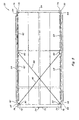
Figure 5 is a simplified top view of a sieve rail assembly of the support structure ofFigure 4 ; -
Figure 6 is a fragmentary top view of the sieve rail assembly ofFigure 5 , illustrating a typical pivotal connection between a rail and compression member thereof, and also illustrating connection of a tension member thereto; -
Figure 7 is a fragmentary perspective exploded view of the sieve rail assembly ofFigure 5 , further illustrating a typical pivotal connection between a rail and compression member, and also connection of a wiper to the rail; -
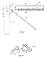
Figure 8 is another fragmentary perspective view of the sieve rail assembly, illustrating further aspects of connection of the tension member; -
Figure 9 is a fragmentary side view of the sieve support structure of the invention, illustrating apparatus for effecting reciprocating movements thereof; -
Figure 10 is a top view of a support structure of a sieve rail assembly the invention, including alternative tension members having adjustable tensioning elements; and -
Figure 11 is a top view of a support structure of a sieve rail assembly the invention, including another alternative arrangement of tension members according to the invention. - Referring now to the drawings, in
Figure 1 a conventionalagricultural combine 20 is shown, illustrating generally the location ofsieve support structure 22 for supporting anupper sieve 24 and alower sieve 26 of acleaning system 28 ofcombine 20.Agricultural combine 20 generally includes a threshing mechanism orseparator 30 operable for receiving crop material from a harvesting mechanism (not shown) on afront end 32 of combine 20,separator 30 being operable for separating smaller grains, seeds, pods and related plant material from larger stalks, stems, leaves, husks and other elements of the crop material, as well as vines, weeds and the like which may be present in the harvested crop material. The smaller material falls fromseparator 30, either directly or indirectly, to cleaningsystem 28, as generally illustrated by arrows A.Cleaning system 28 includes afan 34 disposed forwardly of and just below upper andlower sieves sieves sieves Figures 1 ,2 ,3 and9 ), for cleaning pod fragments and other MOG from the grain, the grain falling throughsieves - In
Figures 2 and3 ,sieves art support structure 36 typically subject to the problems set forth above, namely, deformation such as racking or parallelogramming, and fatigue cracking.Support structure 36 includes an uppersieve rail assembly 38 supportingupper sieve 24, and a lowersieve rail assembly 40 supportinglower sieve 26.Rail assembly 38 andrail assembly 40 each essentially comprises a rectangular structure including parallel, spaced apartside rails respective sieve cross members rails rail cross member - In operation, upper and
lower rail assemblies actuator 50 illustrated inFigure 9 . In one typical arrangement,actuator 50 will be connected in reciprocating driving relation toupper rail assembly 38, and thelower assembly 40 will be suspended fromrail assembly 38 by pivoting members, such that rail assemblies 38 and 40, andsieves Figure 3 , for any of several reasons, including, but not limited to, normal crop material distribution characteristics of the separator, or disposition on a side of a hill, during operation, crop material may be deposited onupper sieve 24 in an uneven manner, particularly, from side to side, as illustrated by the accumulated mass ofcrop material 52. Crop material distribution onlower sieve 24 may also be uneven. As a result, loads exerted againstrail assemblies sieve 24 inFigure 3 , particularly as the sieve is accelerated, decelerated, and/or the direction of the movement of the sieves and rails is reversed. More particularly, during movement in one direction, the side of the sieve supporting the mass ofcrop material 52, and/or any other load or mass distribution that is imbalanced from side to side, will have momentum in that direction compared to the other side, which greater mass and momentum will oppose deceleration and change in the direction of movement to a greater extent than the mass and momentum of the other side of the sieve, resulting in exertion of uneven forces on the supportingrail assembly side rails cross members - Referring also to
FIGS 4 ,5 ,6 ,7 and8 ,sieve support structure 22 of the invention, is shown in greater detail.Support structure 22 includes an uppersieve rail assembly 54 supportingupper sieve 24, and a lowersieve rail assembly 56 supportinglower sieve 26. Uppersieve rail assembly 54 and lowersieve rail assembly 56 can be of the same construction, or can be different, it being preferred that both of therail assemblies sieve rail assembly 54 are described hereinafter, and will be generally representative also oflower rail assembly 56. - More particularly, upper
sieve rail assembly 54 includes an elongatefirst rail 58, and an elongatesecond rail 60 extending substantially parallel tofirst rail 58. Each ofrails combine 20, in spaced apart relation generally beside side sheets enclosing the opposite sides of the cleaning cavity.Rails longitudinally extending lip 62 or other structure adapted for engaging and supporting a side edge portion ofupper sieve 24. Eachrail second end portions end portions 64 are located in a rear portion of the combine cleaning region, and endportions 66 located in a more forward portion. -
Rail assembly 54 includes rigidelongate compression members rails end portions 64 thereof at a rear end ofrail assembly 54, and betweenend portions 66 at the opposite forward end.Compression members Compression members opposite end portions portions rails - One suitable manner of pivotal connection of the end portions of the rails and compression members is illustrated including, but not limited to, pivot pins 76 which enable the rails and compression members to be positioned in a desired angular relation one to the other, for instance, a 90° relation as illustrated, so as to impart a preferred generally rectangular overall shape to rail
assembly 54, which rectangular shape is adapted for use with rectangular sieves such as upper andlower sieves - Referring in particular to
Figures 6 and7 , pivotal connection ofend portion 66 ofrail 60 to endportion 72 ofcompression member 70 using apin 76, is illustrated, and is representative of the other pivotal connections between the members.End portion 72 is bifurcated forming a clevis shape configured for cooperatively receivingend portion 66, in overlapping relation thereto. The overlappingend portions holes 78 through both upper and lower regions of both end portions positioned and sized to be aligned for receiving asuitable pin 76 for pivotally connecting the rail and compression member, which connection serves to restrict relative twisting movements of the rail and compression member, while still allowing relative pivoting movements thereof perpendicular to the axis of the pin, or in what is essentially the plane of the rail assembly. In operation, loads will be transmitted between the rail and compression member through thepin 76, and the pinned connection will be capable of allowing at least some relative pivoting of the connected members, as opposed to being subjected to fatigue cracking, as would be the case with the prior art welded constructions.Pin 76 is retained by suitable apparatus such as a retainingclip 82 received in a hole extending transversely throughpin 76. Alternatively, for instance, a bolt or screw, rivet or other member which allows at least some relative pivotal movement of the rail and compression member could be used. - Referring in particular to
Figures 5 ,6 and 8 , the pivotal connection ofrails compression members compression members rail assembly 54 in the rectangular shape shown, so as to define and enclose a rectangular shaped space configured for receiving upper sieve 24 (Figure 4 ). Importantly, this compression loading is preferably achieved usingtension members space 84, and connect torails connections 90, respectively. Here, it can be observed that, in the embodiment shown,tension members space 84, which can be advantageous as shorter tension members can be used, and it illustrates that, for at least some applications, the tension members need not extend the entire length of the rail assembly. Here also,connections 90 are each relatively simple and comprise a small gusset ortab 92 in connection with therail tab 92 includes ahole 94 adapted for receiving an end oftension member clip 96, as illustrated inFigure 8 . Still further,tension members compression members tension members sieve rail assembly 54 at least substantially to its original rectangular shape, in opposition to a variety of external forces contemplated to be exerted thereagainst, including, but not limited to, those anticipated to arise from uneven loading conditions onsieve 24, and twisting and deformation of surrounding structure of the combine during normal operation. And, in the event that loading conditions are sufficiently great to more substantially deformrail assembly 54tension members tension members sieve 24 when installed, and are of sufficiently small sectional extent so as not to significantly interfere with airflow upwardly throughsieve 24 or crop material flow therefrom. - Referring also to
Figure 9 ,actuator 50 is conventionally constructed and operable for reciprocatingly moving upper and lowersieve rail assemblies sieve rail assembly 54 is supported by both rails thereof for pivotal movement, as denoted by arrow D, by a plurality ofpivot arms 98 having upper ends 100 pivotally mounted to suitable structure ofcombine 20 in the well known manner, such as to side sheets thereof (not shown), and lower ends 102 pivotally connected to rail 58 or 60. Lowersieve rail assembly 56 is connected to uppersieve rail assembly 54 bypivot arms 104 mounted for pivotal movement about a pivot 106, as denoted by arrows E, to suitable structure ofcombine 20, which can also be an adjacent side sheet. Pivotarms 104 haveupper ends 108 pivotally connected toupper rail assembly 54, and lower ends 110 pivotally connected tolower rail assembly 56. A drive arm 112 has alower end 114 connected in eccentrically rotatably driven relation to aneccentric driver 116 of a conventional powered drive (not shown) such as a shaft drive, belt or chain drive, or an electric or fluid motor drive, and anupper end 118 pivotally connected toupper rail assembly 54. When the drive system is rotated, as denoted by arrow F, drive arm 112 causes reciprocating movement ofupper rail assembly 54, as denoted by arrow C, which reciprocatingly pivotspivot arm 104 about pivot 106, as denoted by arrows E, to reciprocatingly movelower rail assembly 56, oppositely in relation toassembly 56, as also denoted by arrow C. Again, it should be noted that other reciprocating or vibrating drive systems can be used. - Referring also to
Figure 10 , uppersieve rail assembly 54 is shown includingalternative tension members tension members Tension members tension members space 84, and connect torails connections 90, respectively.Tension members compression members tension members optional tensioning elements 124, which can comprise, for instance, commercially available turnbuckles of conventional construction. Preferably,tension members sieve rail assembly 54 at least substantially to its original rectangular shape, in opposition to a variety of external forces contemplated to be exerted thereagainst, including, but not limited to, those anticipated to arise from uneven loading conditions and twisting and deformation of surrounding structure of the combine during normal operation. And, in the event that loading conditions are sufficiently great to more substantially deformrail assembly 54tension members tension members Figure 4 ) when installed, and are of sufficiently small sectional extent so as not to significantly interfere with airflow upwardly through the sieve or crop material flow therefrom. - Referring also to
Figure 11 , uppersieve rail assembly 54 is shown with an alternative arrangement fortension members rail assembly 54. - Referring again to
Figures 3 and4 , sieves 24 and 26 are each preferably of well known construction, including a plurality of elongate, horizontally extendingslats 126 pivotable about a sidewardly extending generally horizontal pivotal axis. Eachslat 126 is composed of a plurality of parallel, longitudinally spaced upward and downwardly inclined fingers, the fingers of adjacent ones ofslats 126 defining sieve openings therebetween, for the passage of only plant material of a desired maximum size therethrough, i.e., clean grain.Slats 126 are simultaneously pivotable about the respective pivotal axes through a range of pivotable positions for varying the opening size of the sieve in the well known conventional manner. Sieves 24 and 26 can each comprise a single member or assembly, or can be divided into sections, as desired. - It will be understood that changes in the details, materials, steps, and arrangements of parts which have been described and illustrated, will occur to and may be made by those skilled in the art upon a reading of this disclosure within the scope of the invention as defined in the following claims. The foregoing description illustrates the preferred embodiments of the invention; however, concepts, as based upon the description, may be employed in other embodiments without departing from this scope of the invention.
Claims (10)
- A sieve support structure (22) for installation in an agricultural harvesting machine (20), said support structure comprising:an elongate first rail (42);an elongate second rail (43) at least substantially parallel to the first rail; andrigid elongate cross members (46, 48) connected to and extending between the first and second rails at longitudinally spaced locations therealong, respectively, the rails and the cross members forming a rail assembly (54) having a predetermined shape bounding a space (84) of the predetermined shape, the rail assembly being configured for supporting a generally flat sieve (24) in at least substantially covering relation to the space,characterised in that said support structure further comprises:elongate tension members (86, 88/120, 122) extending generally diagonally through the space and having opposite end portions connected directly or indirectly to the first and second rails (42, 43), respectively, the tension members being tensioned so as to simultaneously urge the rails against the cross members (46, 48) so as to apply a compression load thereagainst for retaining the rail assembly (54) in the predetermined shape.
- A support structure according to claim 1, characterised in that the cross members (46, 48) are pivotally connected to the first and second rails (42, 43).
- A support structure according to claim 2, characterised in that the cross members (46, 48) have end portions (72, 74) that are pivotally connected to end portions (64, 66) of the first and second rails (42, 43), respectively.
- A support structure according to claim 2 or 3, characterised in that the cross members (46, 48) are connected to the first and second rails (42, 43) by removable pins (76).
- A support structure according to any of the preceding claims,
characterised in that at least one of the tension members (86, 88) comprises a rod. - A support structure according to any of the claims 1 to 4, characterised in that at least one of the tension members (120, 122) comprises a cable.
- A support structure according to claim 6, characterised in that the cable (120/122) is provided with a tensioning element (124).
- A support structure according to any of the preceding claims,
characterised in that the predetermined shape (84) is an at least generally rectangular shape, and the tension members (86, 88/120, 122) cross at about a centre region of the space. - A support structure according to any of the preceding claims,
characterised in that it further comprises a second rail assembly (56) for supporting a second sieve (26). - A support structure according to any of the preceding claims,
characterised in that it further comprises an actuator (50) in connection with the rail assembly (54) and operable for moving the assembly and a sieve (24) supported thereon reciprocatingly in a predetermined direction (C) generally parallel to at least one of the first and second rails (42, 43).
Applications Claiming Priority (1)
| Application Number | Priority Date | Filing Date | Title |
|---|---|---|---|
| US11/636,933 US7357711B1 (en) | 2006-12-11 | 2006-12-11 | Sieve support structure for an agricultural combine |
Publications (2)
| Publication Number | Publication Date |
|---|---|
| EP1932420A1 true EP1932420A1 (en) | 2008-06-18 |
| EP1932420B1 EP1932420B1 (en) | 2010-03-24 |
Family
ID=39145316
Family Applications (1)
| Application Number | Title | Priority Date | Filing Date |
|---|---|---|---|
| EP07122780A Active EP1932420B1 (en) | 2006-12-11 | 2007-12-10 | Sieve support structure for an agricultural combine |
Country Status (4)
| Country | Link |
|---|---|
| US (1) | US7357711B1 (en) |
| EP (1) | EP1932420B1 (en) |
| AT (1) | ATE461616T1 (en) |
| DE (1) | DE602007005441D1 (en) |
Cited By (2)
| Publication number | Priority date | Publication date | Assignee | Title |
|---|---|---|---|---|
| EP3120687A1 (en) * | 2015-07-23 | 2017-01-25 | CNH Industrial Belgium nv | Side shaker link for agricultural harvester sieve assembly |
| EP3120688A1 (en) * | 2015-07-23 | 2017-01-25 | CNH Industrial Belgium nv | Structural members for a side shaking sieve arrangement in an agricultural harvester |
Families Citing this family (4)
| Publication number | Priority date | Publication date | Assignee | Title |
|---|---|---|---|---|
| US9258945B2 (en) * | 2013-09-20 | 2016-02-16 | Deere & Company | Hanger mount for a reciprocating sieve |
| US10123486B2 (en) | 2015-07-23 | 2018-11-13 | Cnh Industrial America Llc | Frame for agricultural harvester cleaner |
| US10334781B2 (en) * | 2015-08-20 | 2019-07-02 | Cnh Industrial America Llc | Side shake rate based on machine throughputs |
| US11064656B1 (en) * | 2020-11-02 | 2021-07-20 | Ronald J. Kile | Combine chaffer with chaffer dam |
Citations (4)
| Publication number | Priority date | Publication date | Assignee | Title |
|---|---|---|---|---|
| GB580251A (en) * | 1944-01-27 | 1946-09-02 | Tyler Co W S | Improvements in or relating to screening apparatus |
| US4712568A (en) * | 1986-03-10 | 1987-12-15 | New Holland Inc. | Combine sieve adjustment mechanism |
| EP0629340A1 (en) * | 1993-06-14 | 1994-12-21 | New Holland Belgium N.V. | Harvester sieve opening indicator |
| WO2003082484A1 (en) | 2002-04-02 | 2003-10-09 | Metso Minerals (Brasil) Ltda | Screen support panel for vibrating screens |
Family Cites Families (13)
| Publication number | Priority date | Publication date | Assignee | Title |
|---|---|---|---|---|
| US373382A (en) | 1887-11-15 | Molder s riddle | ||
| US210243A (en) | 1878-11-26 | Improvement in adjustable sieves | ||
| US925623A (en) * | 1905-12-29 | 1909-06-22 | Charles Closz | Adjustable sieve. |
| US2181605A (en) | 1936-10-21 | 1939-11-28 | William E Norvell | Separable sieve for bolters |
| US2247557A (en) | 1939-01-20 | 1941-07-01 | Clarence R Medley | Peanut shelling grate |
| US2413382A (en) * | 1940-11-25 | 1946-12-31 | Hart Carter Co | Sheet metal sieve construction for harvesters |
| US2345947A (en) | 1942-03-05 | 1944-04-04 | Tyler Co W S | Screening apparatus |
| CA1173405A (en) | 1981-10-16 | 1984-08-28 | Cecil T. Humphrey | Dual frequency screen for classifying granular material |
| US6325216B1 (en) | 1993-04-30 | 2001-12-04 | Tuboscope I/P, Inc. | Screen apparatus for vibratory separator |
| US5851393A (en) | 1995-11-14 | 1998-12-22 | Emerson Electric Co. | Screen assembly |
| US6890253B2 (en) * | 2002-01-07 | 2005-05-10 | Hcc, Inc. | Slat and sieve assembly |
| US6726029B2 (en) | 2002-06-12 | 2004-04-27 | Varco I/P, Inc. | Separator screen with solids conveying end area |
| US6953121B2 (en) | 2003-05-06 | 2005-10-11 | Johnson Crushers International | Vibrating screen |
-
2006
- 2006-12-11 US US11/636,933 patent/US7357711B1/en active Active
-
2007
- 2007-12-10 DE DE602007005441T patent/DE602007005441D1/en active Active
- 2007-12-10 EP EP07122780A patent/EP1932420B1/en active Active
- 2007-12-10 AT AT07122780T patent/ATE461616T1/en not_active IP Right Cessation
Patent Citations (4)
| Publication number | Priority date | Publication date | Assignee | Title |
|---|---|---|---|---|
| GB580251A (en) * | 1944-01-27 | 1946-09-02 | Tyler Co W S | Improvements in or relating to screening apparatus |
| US4712568A (en) * | 1986-03-10 | 1987-12-15 | New Holland Inc. | Combine sieve adjustment mechanism |
| EP0629340A1 (en) * | 1993-06-14 | 1994-12-21 | New Holland Belgium N.V. | Harvester sieve opening indicator |
| WO2003082484A1 (en) | 2002-04-02 | 2003-10-09 | Metso Minerals (Brasil) Ltda | Screen support panel for vibrating screens |
Cited By (3)
| Publication number | Priority date | Publication date | Assignee | Title |
|---|---|---|---|---|
| EP3120687A1 (en) * | 2015-07-23 | 2017-01-25 | CNH Industrial Belgium nv | Side shaker link for agricultural harvester sieve assembly |
| EP3120688A1 (en) * | 2015-07-23 | 2017-01-25 | CNH Industrial Belgium nv | Structural members for a side shaking sieve arrangement in an agricultural harvester |
| US10080329B2 (en) | 2015-07-23 | 2018-09-25 | Cnh Industrial America Llc | Side shaker link for agricultural harvester sieve assembly |
Also Published As
| Publication number | Publication date |
|---|---|
| EP1932420B1 (en) | 2010-03-24 |
| ATE461616T1 (en) | 2010-04-15 |
| US7357711B1 (en) | 2008-04-15 |
| DE602007005441D1 (en) | 2010-05-06 |
Similar Documents
| Publication | Publication Date | Title |
|---|---|---|
| US6843719B1 (en) | Floating combine sieve assembly | |
| US7946908B2 (en) | Flexible louver opening adjustment mechanism for a pivoting combine harvester cleaning element | |
| EP1932420B1 (en) | Sieve support structure for an agricultural combine | |
| CN106576622A (en) | Latch mechanism for agricultural harvester concaves | |
| RU2729159C2 (en) | Agricultural harvesting machine with a sloping grain board moving in a lateral direction | |
| CN101953258A (en) | Cleaning device and combine harvester comprising cleaning device | |
| KR101772867B1 (en) | Swing sorting device of harvester | |
| EP3120687B1 (en) | Side shaker link for agricultural harvester sieve assembly | |
| EP3103318A1 (en) | Grain tank with force assisting element for cover | |
| EP3646707B1 (en) | Improved cleaning system for a combine | |
| EP3772270B1 (en) | Automatic header latch | |
| EP3275304B1 (en) | Lateral shake mechanism for agricultural harvester cleaner | |
| US10123486B2 (en) | Frame for agricultural harvester cleaner | |
| EP3530105B1 (en) | An adjustment and suspension device for concaves | |
| JP6849427B2 (en) | combine | |
| EP3120686B1 (en) | Linkage for agricultural harvester cleaner | |
| EP3120688B1 (en) | Structural members for a side shaking sieve arrangement in an agricultural harvester | |
| JP7588534B2 (en) | combine | |
| JP6922029B2 (en) | combine | |
| EP4091431B1 (en) | Sieve for an agricultural harvester including extruded sides with strips | |
| JP2021090473A5 (en) | ||
| JP7670761B2 (en) | combine | |
| US20250151660A1 (en) | Sieve assembly for separating grains from plant residual material | |
| EP4548745A1 (en) | Feederhouse for a combine harvester | |
| CN1018327B (en) | Threshing apparatus |
Legal Events
| Date | Code | Title | Description |
|---|---|---|---|
| PUAI | Public reference made under article 153(3) epc to a published international application that has entered the european phase |
Free format text: ORIGINAL CODE: 0009012 |
|
| AK | Designated contracting states |
Kind code of ref document: A1 Designated state(s): AT BE BG CH CY CZ DE DK EE ES FI FR GB GR HU IE IS IT LI LT LU LV MC MT NL PL PT RO SE SI SK TR |
|
| AX | Request for extension of the european patent |
Extension state: AL BA HR MK RS |
|
| 17P | Request for examination filed |
Effective date: 20081218 |
|
| AKX | Designation fees paid |
Designated state(s): AT BE BG CH CY CZ DE DK EE ES FI FR GB GR HU IE IS IT LI LT LU LV MC MT NL PL PT RO SE SI SK TR |
|
| 17Q | First examination report despatched |
Effective date: 20090212 |
|
| GRAP | Despatch of communication of intention to grant a patent |
Free format text: ORIGINAL CODE: EPIDOSNIGR1 |
|
| GRAS | Grant fee paid |
Free format text: ORIGINAL CODE: EPIDOSNIGR3 |
|
| GRAA | (expected) grant |
Free format text: ORIGINAL CODE: 0009210 |
|
| AK | Designated contracting states |
Kind code of ref document: B1 Designated state(s): AT BE BG CH CY CZ DE DK EE ES FI FR GB GR HU IE IS IT LI LT LU LV MC MT NL PL PT RO SE SI SK TR |
|
| REG | Reference to a national code |
Ref country code: GB Ref legal event code: FG4D |
|
| REG | Reference to a national code |
Ref country code: CH Ref legal event code: EP |
|
| REG | Reference to a national code |
Ref country code: IE Ref legal event code: FG4D |
|
| REF | Corresponds to: |
Ref document number: 602007005441 Country of ref document: DE Date of ref document: 20100506 Kind code of ref document: P |
|
| REG | Reference to a national code |
Ref country code: NL Ref legal event code: VDEP Effective date: 20100324 |
|
| PG25 | Lapsed in a contracting state [announced via postgrant information from national office to epo] |
Ref country code: LT Free format text: LAPSE BECAUSE OF FAILURE TO SUBMIT A TRANSLATION OF THE DESCRIPTION OR TO PAY THE FEE WITHIN THE PRESCRIBED TIME-LIMIT Effective date: 20100324 |
|
| LTIE | Lt: invalidation of european patent or patent extension |
Effective date: 20100324 |
|
| PG25 | Lapsed in a contracting state [announced via postgrant information from national office to epo] |
Ref country code: AT Free format text: LAPSE BECAUSE OF FAILURE TO SUBMIT A TRANSLATION OF THE DESCRIPTION OR TO PAY THE FEE WITHIN THE PRESCRIBED TIME-LIMIT Effective date: 20100324 Ref country code: SI Free format text: LAPSE BECAUSE OF FAILURE TO SUBMIT A TRANSLATION OF THE DESCRIPTION OR TO PAY THE FEE WITHIN THE PRESCRIBED TIME-LIMIT Effective date: 20100324 Ref country code: PL Free format text: LAPSE BECAUSE OF FAILURE TO SUBMIT A TRANSLATION OF THE DESCRIPTION OR TO PAY THE FEE WITHIN THE PRESCRIBED TIME-LIMIT Effective date: 20100324 Ref country code: LV Free format text: LAPSE BECAUSE OF FAILURE TO SUBMIT A TRANSLATION OF THE DESCRIPTION OR TO PAY THE FEE WITHIN THE PRESCRIBED TIME-LIMIT Effective date: 20100324 Ref country code: FI Free format text: LAPSE BECAUSE OF FAILURE TO SUBMIT A TRANSLATION OF THE DESCRIPTION OR TO PAY THE FEE WITHIN THE PRESCRIBED TIME-LIMIT Effective date: 20100324 |
|
| PG25 | Lapsed in a contracting state [announced via postgrant information from national office to epo] |
Ref country code: ES Free format text: LAPSE BECAUSE OF FAILURE TO SUBMIT A TRANSLATION OF THE DESCRIPTION OR TO PAY THE FEE WITHIN THE PRESCRIBED TIME-LIMIT Effective date: 20100705 Ref country code: EE Free format text: LAPSE BECAUSE OF FAILURE TO SUBMIT A TRANSLATION OF THE DESCRIPTION OR TO PAY THE FEE WITHIN THE PRESCRIBED TIME-LIMIT Effective date: 20100324 Ref country code: BE Free format text: LAPSE BECAUSE OF FAILURE TO SUBMIT A TRANSLATION OF THE DESCRIPTION OR TO PAY THE FEE WITHIN THE PRESCRIBED TIME-LIMIT Effective date: 20100324 Ref country code: SE Free format text: LAPSE BECAUSE OF FAILURE TO SUBMIT A TRANSLATION OF THE DESCRIPTION OR TO PAY THE FEE WITHIN THE PRESCRIBED TIME-LIMIT Effective date: 20100324 Ref country code: GR Free format text: LAPSE BECAUSE OF FAILURE TO SUBMIT A TRANSLATION OF THE DESCRIPTION OR TO PAY THE FEE WITHIN THE PRESCRIBED TIME-LIMIT Effective date: 20100625 Ref country code: RO Free format text: LAPSE BECAUSE OF FAILURE TO SUBMIT A TRANSLATION OF THE DESCRIPTION OR TO PAY THE FEE WITHIN THE PRESCRIBED TIME-LIMIT Effective date: 20100324 Ref country code: NL Free format text: LAPSE BECAUSE OF FAILURE TO SUBMIT A TRANSLATION OF THE DESCRIPTION OR TO PAY THE FEE WITHIN THE PRESCRIBED TIME-LIMIT Effective date: 20100324 |
|
| PG25 | Lapsed in a contracting state [announced via postgrant information from national office to epo] |
Ref country code: CZ Free format text: LAPSE BECAUSE OF FAILURE TO SUBMIT A TRANSLATION OF THE DESCRIPTION OR TO PAY THE FEE WITHIN THE PRESCRIBED TIME-LIMIT Effective date: 20100324 Ref country code: SK Free format text: LAPSE BECAUSE OF FAILURE TO SUBMIT A TRANSLATION OF THE DESCRIPTION OR TO PAY THE FEE WITHIN THE PRESCRIBED TIME-LIMIT Effective date: 20100324 Ref country code: BG Free format text: LAPSE BECAUSE OF FAILURE TO SUBMIT A TRANSLATION OF THE DESCRIPTION OR TO PAY THE FEE WITHIN THE PRESCRIBED TIME-LIMIT Effective date: 20100624 Ref country code: IS Free format text: LAPSE BECAUSE OF FAILURE TO SUBMIT A TRANSLATION OF THE DESCRIPTION OR TO PAY THE FEE WITHIN THE PRESCRIBED TIME-LIMIT Effective date: 20100724 |
|
| PLBE | No opposition filed within time limit |
Free format text: ORIGINAL CODE: 0009261 |
|
| STAA | Information on the status of an ep patent application or granted ep patent |
Free format text: STATUS: NO OPPOSITION FILED WITHIN TIME LIMIT |
|
| PG25 | Lapsed in a contracting state [announced via postgrant information from national office to epo] |
Ref country code: DK Free format text: LAPSE BECAUSE OF FAILURE TO SUBMIT A TRANSLATION OF THE DESCRIPTION OR TO PAY THE FEE WITHIN THE PRESCRIBED TIME-LIMIT Effective date: 20100324 Ref country code: PT Free format text: LAPSE BECAUSE OF FAILURE TO SUBMIT A TRANSLATION OF THE DESCRIPTION OR TO PAY THE FEE WITHIN THE PRESCRIBED TIME-LIMIT Effective date: 20100726 |
|
| 26N | No opposition filed |
Effective date: 20101228 |
|
| PG25 | Lapsed in a contracting state [announced via postgrant information from national office to epo] |
Ref country code: MC Free format text: LAPSE BECAUSE OF NON-PAYMENT OF DUE FEES Effective date: 20101231 |
|
| PG25 | Lapsed in a contracting state [announced via postgrant information from national office to epo] |
Ref country code: IE Free format text: LAPSE BECAUSE OF NON-PAYMENT OF DUE FEES Effective date: 20101210 |
|
| PG25 | Lapsed in a contracting state [announced via postgrant information from national office to epo] |
Ref country code: MT Free format text: LAPSE BECAUSE OF FAILURE TO SUBMIT A TRANSLATION OF THE DESCRIPTION OR TO PAY THE FEE WITHIN THE PRESCRIBED TIME-LIMIT Effective date: 20100324 Ref country code: IT Free format text: LAPSE BECAUSE OF NON-PAYMENT OF DUE FEES Effective date: 20101210 |
|
| REG | Reference to a national code |
Ref country code: CH Ref legal event code: PL |
|
| PG25 | Lapsed in a contracting state [announced via postgrant information from national office to epo] |
Ref country code: CY Free format text: LAPSE BECAUSE OF FAILURE TO SUBMIT A TRANSLATION OF THE DESCRIPTION OR TO PAY THE FEE WITHIN THE PRESCRIBED TIME-LIMIT Effective date: 20100324 |
|
| PG25 | Lapsed in a contracting state [announced via postgrant information from national office to epo] |
Ref country code: HU Free format text: LAPSE BECAUSE OF FAILURE TO SUBMIT A TRANSLATION OF THE DESCRIPTION OR TO PAY THE FEE WITHIN THE PRESCRIBED TIME-LIMIT Effective date: 20100925 Ref country code: LU Free format text: LAPSE BECAUSE OF NON-PAYMENT OF DUE FEES Effective date: 20101210 |
|
| PG25 | Lapsed in a contracting state [announced via postgrant information from national office to epo] |
Ref country code: CH Free format text: LAPSE BECAUSE OF NON-PAYMENT OF DUE FEES Effective date: 20111231 Ref country code: LI Free format text: LAPSE BECAUSE OF NON-PAYMENT OF DUE FEES Effective date: 20111231 Ref country code: TR Free format text: LAPSE BECAUSE OF FAILURE TO SUBMIT A TRANSLATION OF THE DESCRIPTION OR TO PAY THE FEE WITHIN THE PRESCRIBED TIME-LIMIT Effective date: 20100324 |
|
| REG | Reference to a national code |
Ref country code: DE Ref legal event code: R082 Ref document number: 602007005441 Country of ref document: DE Representative=s name: PATENTANWAELTE WALLACH, KOCH & PARTNER, DE |
|
| REG | Reference to a national code |
Ref country code: DE Ref legal event code: R081 Ref document number: 602007005441 Country of ref document: DE Owner name: CNH INDUSTRIAL BELGIUM NV, BE Free format text: FORMER OWNER: CNH BELGIUM NV, ZEDELGEM, BE Effective date: 20140428 Ref country code: DE Ref legal event code: R082 Ref document number: 602007005441 Country of ref document: DE Representative=s name: PATENTANWAELTE WALLACH, KOCH & PARTNER, DE Effective date: 20140428 Ref country code: DE Ref legal event code: R082 Ref document number: 602007005441 Country of ref document: DE Representative=s name: PATENTANWAELTE WALLACH, KOCH, DR. HAIBACH, FEL, DE Effective date: 20140428 |
|
| REG | Reference to a national code |
Ref country code: FR Ref legal event code: CD Owner name: CNH INDUSTRIAL BELGIUM NV Effective date: 20140725 |
|
| REG | Reference to a national code |
Ref country code: FR Ref legal event code: PLFP Year of fee payment: 9 |
|
| REG | Reference to a national code |
Ref country code: FR Ref legal event code: PLFP Year of fee payment: 10 |
|
| REG | Reference to a national code |
Ref country code: FR Ref legal event code: PLFP Year of fee payment: 11 |
|
| REG | Reference to a national code |
Ref country code: FR Ref legal event code: PLFP Year of fee payment: 12 |
|
| PGFP | Annual fee paid to national office [announced via postgrant information from national office to epo] |
Ref country code: IT Payment date: 20191206 Year of fee payment: 13 |
|
| PGFP | Annual fee paid to national office [announced via postgrant information from national office to epo] |
Ref country code: GB Payment date: 20191220 Year of fee payment: 13 |
|
| REG | Reference to a national code |
Ref country code: DE Ref legal event code: R082 Ref document number: 602007005441 Country of ref document: DE Representative=s name: MEISSNER BOLTE PATENTANWAELTE RECHTSANWAELTE P, DE |
|
| REG | Reference to a national code |
Ref country code: DE Ref legal event code: R084 Ref document number: 602007005441 Country of ref document: DE |
|
| GBPC | Gb: european patent ceased through non-payment of renewal fee |
Effective date: 20201210 |
|
| PG25 | Lapsed in a contracting state [announced via postgrant information from national office to epo] |
Ref country code: IT Free format text: LAPSE BECAUSE OF NON-PAYMENT OF DUE FEES Effective date: 20201210 |
|
| PG25 | Lapsed in a contracting state [announced via postgrant information from national office to epo] |
Ref country code: GB Free format text: LAPSE BECAUSE OF NON-PAYMENT OF DUE FEES Effective date: 20201210 |
|
| PGFP | Annual fee paid to national office [announced via postgrant information from national office to epo] |
Ref country code: FR Payment date: 20221216 Year of fee payment: 16 |
|
| PG25 | Lapsed in a contracting state [announced via postgrant information from national office to epo] |
Ref country code: FR Free format text: LAPSE BECAUSE OF NON-PAYMENT OF DUE FEES Effective date: 20231231 |
|
| PG25 | Lapsed in a contracting state [announced via postgrant information from national office to epo] |
Ref country code: FR Free format text: LAPSE BECAUSE OF NON-PAYMENT OF DUE FEES Effective date: 20231231 |
|
| PGFP | Annual fee paid to national office [announced via postgrant information from national office to epo] |
Ref country code: DE Payment date: 20251229 Year of fee payment: 19 |