EP1930675B1 - Refrigerator and control method thereof - Google Patents
Refrigerator and control method thereof Download PDFInfo
- Publication number
- EP1930675B1 EP1930675B1 EP07121897.8A EP07121897A EP1930675B1 EP 1930675 B1 EP1930675 B1 EP 1930675B1 EP 07121897 A EP07121897 A EP 07121897A EP 1930675 B1 EP1930675 B1 EP 1930675B1
- Authority
- EP
- European Patent Office
- Prior art keywords
- door opening
- driving motor
- inputted
- doors
- refrigerator according
- Prior art date
- Legal status (The legal status is an assumption and is not a legal conclusion. Google has not performed a legal analysis and makes no representation as to the accuracy of the status listed.)
- Ceased
Links
Images





Classifications
-
- F—MECHANICAL ENGINEERING; LIGHTING; HEATING; WEAPONS; BLASTING
- F25—REFRIGERATION OR COOLING; COMBINED HEATING AND REFRIGERATION SYSTEMS; HEAT PUMP SYSTEMS; MANUFACTURE OR STORAGE OF ICE; LIQUEFACTION SOLIDIFICATION OF GASES
- F25D—REFRIGERATORS; COLD ROOMS; ICE-BOXES; COOLING OR FREEZING APPARATUS NOT OTHERWISE PROVIDED FOR
- F25D23/00—General constructional features
- F25D23/02—Doors; Covers
- F25D23/028—Details
-
- F—MECHANICAL ENGINEERING; LIGHTING; HEATING; WEAPONS; BLASTING
- F25—REFRIGERATION OR COOLING; COMBINED HEATING AND REFRIGERATION SYSTEMS; HEAT PUMP SYSTEMS; MANUFACTURE OR STORAGE OF ICE; LIQUEFACTION SOLIDIFICATION OF GASES
- F25D—REFRIGERATORS; COLD ROOMS; ICE-BOXES; COOLING OR FREEZING APPARATUS NOT OTHERWISE PROVIDED FOR
- F25D2323/00—General constructional features not provided for in other groups of this subclass
- F25D2323/02—Details of doors or covers not otherwise covered
- F25D2323/021—French doors
-
- F—MECHANICAL ENGINEERING; LIGHTING; HEATING; WEAPONS; BLASTING
- F25—REFRIGERATION OR COOLING; COMBINED HEATING AND REFRIGERATION SYSTEMS; HEAT PUMP SYSTEMS; MANUFACTURE OR STORAGE OF ICE; LIQUEFACTION SOLIDIFICATION OF GASES
- F25D—REFRIGERATORS; COLD ROOMS; ICE-BOXES; COOLING OR FREEZING APPARATUS NOT OTHERWISE PROVIDED FOR
- F25D2400/00—General features of, or devices for refrigerators, cold rooms, ice-boxes, or for cooling or freezing apparatus not covered by any other subclass
- F25D2400/06—Refrigerators with a vertical mullion
Definitions
- the present invention relates to a refrigerator and a control method thereof, and particularly, to a refrigerator including a door opening device to easily open a door and a control method thereof.
- Korean Unexamined Patent Application Publication No. 2006-40436 discloses a refrigerator including a door opening device.
- This refrigerator is a side by side refrigerator including compartments partitioned at both sides thereof and a left door and a right door to open and close the respective compartments.
- the opening device includes a driving motor to rotate forward and backward, and a main cam rotated by the driving motor.
- the door opening device further includes a first sub-cam driven by the main cam to open the left door and a second sub-cam driven by the main cam to open the right door.
- the door opening device opens the left door by which, due to the rotation of the driving motor, the main cam rotates clockwise to drive the first sub-cam. Due to the reverse rotation of the driving motor, the main cam rotates counterclockwise to drive the second sub-cam, resulting in opening the right door.
- this door opening device drives the main cam by the forward rotation of the driving motor clockwise and returns the main cam to an initial position by the reverse rotation of the driving motor counterclockwise after opening the door, the driving motor must be rotated twice to open a single door. In other words, the driving motor must rotate forward and in reverse.
- the driving motor since the driving motor is frequently driven, the lifespan of the driving motor and a relay to control the driving motor could be shortened.
- the driving motor in order to open one of the doors, is driven according to rotating in a first direction, rotating in a second direction opposite to the first direction to be returned to the initial position, further rotating in the second direction to open the other door, and rotating in the first direction to be returned to the initial position.
- the driving motor is frequently driven and the opening of the doors is delayed.
- Another aspect of the invention is to provide a refrigerator in which it is determined whether a door opening device is malfunctioning and malfunction of a driving motor due to chattering of a driving motor driving unit is prevented, and a control method thereof.
- Still another aspect of the invention is to provide a refrigerator in which a door opening device is prevented from damage due to excessive operation thereof and a control method thereof.
- a refrigerator comprising a main body defining first and second compartments therein; first and second doors to respectively open and close the first and second compartments; a door opening device comprising: a switch to input a plurality of door opening signals respectively corresponding to the first and second doors to respectively open the first and second doors, an actuating member to rotate to selectively open the first and second doors, a rotation cam including a plurality of protrusions to contact and rotate the actuating member and a plurality of spacing portions spaced apart from the actuating member, the protrusions and the spacing portions being alternately disposed in a rotation direction, a driving motor to rotate the rotation cam forward and in reverse, and a return device to return the actuating member to an initial position after opening one of the first and second doors; and a controller to control the door opening device in accordance with the door opening signals when the door opening signals are inputted to the switch.
- the controller accepts only a first inputted one of the door opening signals when both the plurality of the door opening signals for the first and second doors are inputted, and rotates the driving motor in a first direction in order to open the door corresponding to the accepted door opening signal.
- the controller disregards the door opening signals for the first and second doors when the door opening signals are inputted simultaneously.
- the controller accepts only the door opening signal corresponding to a preset one of the first and second doors when the door opening signals are inputted simultaneously.
- the controller disregards the inputted door opening signal.
- the refrigerator further comprises a door opening sensor to detect whether the doors are opened, and the controller disregards the inputted door opening signal when the door opening sensor detects the door corresponding to the inputted door opening signal.
- the door opening device further comprises a position detecting unit to detect a rotation position of the rotation cam to control the driving motor, the position detecting unit having a portion contacting the protrusions during the rotation of the actuating member and being positioned opposite a first one of the protrusions of the rotation cam at the initial state when the door opening signal is not accepted, and the controller determines the rotation position of the rotation cam detected by the position detecting unit when any one of the door opening signals is accepted, and rotates the driving motor in the first direction such that the rotation cam rotates until the protrusion adjacent the first one of the protrusions is opposite the position detecting unit.
- the position detecting unit comprises magnets disposed at leading edges of the respective protrusions and a detecting sensor installed to an outer side of the rotation cam to detect the magnets.
- the refrigerator further comprises a display to display a malfunction of the door opening device, and the controller determines the door opening device has malfunctioned when the protrusion adjacent to the first protrusion is not detected within a first predetermined time and controls the display to display the malfunction.
- the controller rotates the driving motor for a second predetermined time before detecting the rotation position of the rotation cam when the door opening signals are accepted.
- the controller disregards the rotation position of the rotation cam for a third predetermined time and rotates the driving motor in the first direction when the spacing portions are detected during the rotation of the driving motor.
- the controller rotates the driving motor in either the first or second direction until the protrusion adjacent to the first protrusion is detected for an initial malfunction diagnosis.
- the controller determines the door opening device malfunctioned and controls the display to display the malfunction.
- the controller in the initial malfunction diagnosis, first rotates the driving motor for the second predetermined time before detecting the rotation position of the rotation cam.
- the controller determines a frequency of the opening of the doors due to the door opening signals inputted to the switches during the control of the door opening device, and when the frequency is greater than a fourth predetermined time, the controller performs a locking mode of the door opening device that the door opening device is not operated even when the door opening signals are inputted.
- the controller When the door opening signals are not inputted for a fifth predetermined time while the locking mode of the door opening device is performed, the controller performs a driving mode of the door opening device that the locking mode of the door opening device is released and the door opening device is driven in accordance with an inputted door opening signal.
- the refrigerator further comprises an input unit to input any one operation mode of the locking mode and the driving mode of the door opening device, and when the operation mode is inputted to the input unit by a control signal of a user, the controller firstly performs the inputted operation mode regardless of the frequency that the doors are opened by the door opening signals.
- the controller controls the display to display the performing operation mode.
- a method of controlling a refrigerator comprising: a main body defining first and second compartments therein; a first door and a second door to respectively open and close the first and second compartments, a door opening device comprising: a switch to input a plurality of door opening signals respectively corresponding to the first and second doors to respectively opening the first and second doors, an actuating member to rotate to selectively open the first and second doors a rotation cam including a plurality of protrusions to contact and rotate the actuating member and a plurality of spacing portions spaced apart from the actuating member, the protrusions and the spacing portions being alternately disposed in a rotation direction, a driving motor to rotate the rotation cam forward and in reverse, and a return device to return the actuating member to an initial position after opening one of the first and second doors, the method comprising: controlling the door opening device in accordance with the door opening signals when the door opening signals are inputted to the switch.
- the method further comprises accepting only a first inputted one of the door opening signals and rotating the driving motor is rotated in a first direction in order to open the door corresponding to the accepted door opening signal.
- the door opening signals for the two doors or accepting only one of the door opening signals comprises presetting one of the two doors when the door opening signals are inputted simultaneously.
- the method further comprises disregarding the inputted door opening signal.
- the inputted door opening signal is disregarded.
- the door opening device further comprises a position detecting sensor to detect a positing of the rotating cam, the position detecting sensor being opposite a first one of the protrusions when the door opening signal is accepted, and the method further comprises detecting the rotation position of the rotation cam, and the driving motor is rotated in a first direction such that the rotation cam rotates until a second one of the protrusions is opposite the position detecting sensor, the second protrusion being adjacent the first protrusion.
- the position detecting unit comprises a detecting sensor, installed to an outer side of the rotation cam, the method further comprising detecting magnets disposed at leading edges of the respective protrusions.
- the method further comprises determining that the door opening device is malfunctioning and the malfunctioned state is displayed.
- the method further comprises rotating the driving motor for a second predetermined time before detecting the rotation position of the rotation cam.
- the method further comprises when the spacing portions are detected during the rotation of the driving motor, disregarding the rotation position of the rotation cam for a third predetermined time and rotating the driving motor in the first direction.
- the method further comprises performing an initial malfunction diagnosis while rotating the driving motor in any direction until the second protrusion disposed next to a current position is detected.
- the method further comprises determining that the door opening device is malfunctioning and the display displays the malfunction.
- the method further comprises rotating during the performing the initial malfunction diagnosis, the method further comprises rotating the driving motor is for the second predetermined time before detecting the rotation position of the rotation cam.
- the method comprises not operating a locking mode of the door opening device even when the door opening signals are inputted.
- the method comprises performing a driving mode of the door opening device that the locking mode of the door opening device is released and the door opening device is driven in accordance with an inputted door opening signal.
- the method comprises performing the inputted operation mode first regardless of the frequency that the doors are opened by the door opening signals.
- FIG. 1 is a perspective view illustrating a refrigerator employing a door opening device according to a first embodiment of the present invention.
- the refrigerator includes a main body which is partitioned into a first compartment (not shown) and a second compartment (not shown).
- a first door 11 and a second door 12 are installed on sides of the main body 10 to open the first and second compartments, respectively.
- the first compartment forms a freezer compartment
- the second compartment forms a refrigerator compartment.
- the first and second doors 11 and 12 are coupled with the main body 10 to be pivoted by hinges 13 at respective upper and lower sides.
- the respective doors 11 and 12 are provided with handles 14 and 15 formed in the front sides thereof.
- a door opening device 20 is installed to an upper side of the main body 10.
- the door opening device 20 pushes the upper sides of the first and second doors 11 and 12 to open the respective doors 11 and 12 such that a user can easily open the doors.
- FIGS. 2 to 6 illustrate the door opening device 20 according to the first embodiment of the present invention
- FIG. 7 is a block diagram illustrating operation of the door opening device 20.
- the door opening device 20 includes an actuating member 30 to selectively open the doors 11 and 12 by rotation, a rotation cam 40 to rotate the actuating member 30 for the opening of the doors 11 and 12, and a driving motor 50 to rotate the rotation cam 40 forward and in reverse.
- the door opening device 20 further includes a cam cover 52 to accommodate the rotation cam 40 and an upper cover 21 to cover the upper side of the device.
- the rotation cam 40 includes three protrusions 41 to contact and rotate the actuating member 30 and three spacing portions 42 spaced apart from the actuating member 30.
- the respective protrusions 41 and spacing portions 42 are alternately disposed in the rotation direction, and the protrusions 41 are arranged every 120 degrees.
- the respective protrusions 41 have a convex curved shape and the respective spacing portions 42 have a concave curved shape.
- the numbers of the protrusions 41 and the spacing portions 42 are, for example, three, different numbers of the protrusions 41 and the spacing portions 42 can be utilized so long as adequate performance can be carried out.
- the cam cover 52 to accommodate the rotation cam 40 is fixed to the upper side of the refrigerator main body 10 by fastening fixing screws 53, and the driving motor 50 is fixed to the upper side of the cam cover 52.
- the shaft 51 of the driving motor 50 penetrates the cam cover 52 and extends into the cam cover 52 to be coupled with the rotation cam 40.
- the rotation cam 40 rotates within the cam cover 52 during the operation of the driving motor 50.
- the actuating member 30 is coupled to the upper side of the main body 10 in front of the rotation cam 40.
- the main body 10 for the coupling, includes a supporting shaft 23 provided on the upper side.
- a fastening screw 24 is fastened to the supporting shaft 23 to prevent the actuating member 30 from being separated after the coupling of the actuating member 30.
- the actuating member 30, as illustrated in FIG. 3 includes a first extending part 31 extended from a center of rotation to the rotation cam 40, a second extending part 32 extended inward from the center of rotation, and a third extending part 33 extended from the center of rotation to the inside of the second door 12.
- the actuating member 30 has a "Y"-shape.
- the first extending part 31 of the actuating member 30 contacts the protrusions 41 of the rotation cam 40 at its end, and has a length long enough to be spaced apart from the spacing portions 42 of the rotation cam 40.
- a distance L1 from an end of the first extending part 31 of the actuating member 30 to the center of rotation is longer than a distance L2 from ends of the second and third extending parts 32 and 33 to the center of rotation.
- This is designed by applying the principle of the lever, as illustrated in FIGS. 4 and 6 , such that the second extending part 32 or the third extending part 33 presses the inner surface of the first or second doors 11 or 12 with a large force to easily open the first and second doors 11 and 12 even when the rotation cam 40 rotates the first extending part 31 of the actuating member 30 with a small force.
- the ends of the first, second, and third extending parts 31, 32, and 33 of the actuating member 30 are installed with rollers 34, respectively. This is to prevent friction between the first extending part 31 and the rotation cam 40 and friction between the second and third extending parts 32 and 33 and the first and second doors 11 and 12, when the door opening device 20 is driven.
- the first extending part 31 of the actuating member 30 is installed with a return spring 25 to return the actuating member 30 to an initial position after opening the doors.
- the return spring 25 includes an end connected to the first extending part 31 and the other end connected to the upper side of the main body 10 to provide an elastic returning force to the first extending part 31.
- a coil type return spring 25 is depicted as a device to return the actuating member in the drawing, the device may be an elastic member such as a torsion spring, spiral spring, rubber, or the like.
- the actuating member 30 since the actuating member 30 receives the elasticity of the return spring 25, the actuating member 30, as illustrated in FIG. 3 , returns to the initial position. Moreover, in the initial state, the end of the first extending part 31 is positioned at one of the spacing portions 42 of the rotation cam 40 and the driving motor 50 is stopped when positions of the spacing portion 42 and the first extending part 31 are the same.
- the door opening device 20 includes a position detecting unit 110 to detect a rotation position of the rotation cam 40 to control the driving motor 50.
- the position detecting unit 110 includes magnets 43 disposed at leading edges of the protrusions 41 of the rotation cam 40 and position detecting sensor 44 fixed to the outer cam cover 52 to detect the magnets 43.
- the position detecting sensor 44 may be a conventional reed switch, in this embodiment, as an example, the reed switch is turned on when the position detecting sensor 44 faces one of the magnets 43 of the protrusions 41, and is turned off when the position detecting sensor 44 faces one of the spacing portions 42, and vice versa.
- the position detecting unit 110 is not limited to the above-description, but may be a photo sensor to detect the positions of the protrusions 41, or a limit switch to detect the position by contacting the protrusions 41.
- the upper cover 21 is spaced apart from and covers the actuating member 30 and the upper side of the driving motor 50, and fixed to the upper side of the main body 10 by plural fixing screws 22.
- the door opening device 20 includes switches 16 and 17 respectively installed to the handles 14 and 15 of the first and second doors 11 and 12.
- the switches 16 and 17 may be sensors to detect that a user holds the handles 14 and 15 or a power switch to be directly opened and closed such that power is supplied to the driving motor 50.
- the driving motor 50 does not work.
- the initial state is maintained.
- the first extending part 31 of the actuating member 30 is positioned at the central position of one of the spacing portions 42 of the rotation cam 40.
- the switch 16 is activated to drive the driving motor 50.
- the rotation cam 40 rotates forward (clockwise) due to the driving motor 50 and one of the protrusions 41 pushes the first extending part 31 of the actuating member 30, the actuating member 30 rotates counterclockwise.
- the second extending part 32 pushes the inner side of the door 11, resulting in easy opening of the first door 11.
- the rotation cam 40 rotates by 120 degrees clockwise and the position detecting sensor 44 detects the magnets 43 disposed to the protrusions 41, the driving motor 50 is stopped.
- the switch 17 is activated to drive the driving motor 50 in reverse.
- the rotation cam 40 rotates counterclockwise in reverse due to the driving motor 50 and one of the protrusions 41 pushes the first extending part 31 of the actuating member 30, the actuating member rotates clockwise.
- the third extending part 33 pushes the inner side of the second door 12 to open the second door 12.
- the third extending part 33 pushes the inner side of the second door 12 to open the second door 12.
- the rotation cam 40 rotates by 120 degrees and is stopped, and the actuating member 30 returns to the initial state due to the elasticity of the return spring 25.
- the driving motor 50 rotates once in any one direction to sufficiently open the respective doors 11 and 12, the operation of the driving motor 50 can be minimized.
- both of the doors 11 and 12 can be opened by only the clockwise and counterclockwise rotations of the driving motor 50.
- the time of operation of the driving motor 50 can be significantly reduced as well and the two doors 11 and 12 can be rapidly opened as a result.
- the operation of the door opening device 20, as illustrated in the block diagram of FIG. 7 is performed as follows.
- a controller 100 transmits a signal to control the driving motor 50 to a motor driving unit 150 in accordance with a program stored in a memory 130 using information transmitted from the position detecting unit 110 and a timer 140.
- the controller 100 determines whether the driving motor 50 is driven or not, using the information transmitted from a door opening sensor 120 to detect whether the two doors 11 and 12 are opened or not, when the door opening signals are input.
- the controller 100 determines the door opening device 20 is malfunctioning or not in an initial state when power is supplied, or during operation of the door opening device 20, and transmits a control signal to indicate the malfunction to a display 160 when the door opening device 20 is malfunctioning.
- FIG. 8 is a flowchart illustrating an initial malfunction diagnosing method of the door opening device 20 according to the first embodiment of the present invention.
- the controller 100 transmits a signal to rotate the driving motor 50 clockwise for a first predetermined time to the motor driving unit 150 (S210). The reason that this operation is performed will be described later.
- the controller 100 continues to rotate the driving motor and operates the timer 140 (S220), and determines whether rotation time T of the driving motor 50 exceeds a second predetermined time (S230).
- the controller 100 determines whether the position detecting sensor 44, the reed switch, is turned off. If not, the operation S230 is performed again. If it is determined to be turned off, the controller 100 continues to rotate the driving motor 50 forward (S240 and S250).
- the controller 100 transmits a signal to indicate the malfunction of the door opening device 20 to the display 160 and completes the control (S300).
- the controller 100 activates the timer 140 (S260), any determines whether the rotation time T of the driving motor 50 exceeds a third predetermined time (S270).
- the controller 100 determines whether the position detecting sensor 44 is turned on. If not, the controller 100 performs the operation S270. If the position detecting sensor 44 is turned on, the controller 100 determines a normal state of the door opening device 20 and stops the driving motor 50 (S280 and S290).
- the controller 100 performs operation S300.
- the second predetermined time and the third predetermined time are values that are obtained by experiment and stored in the memory 130, and are determined by a maximum time for the state of the position detecting sensor 44 to be changed from the turned on state to the turned off state or from the turned off state to the turned on state when the door opening device 20 is normal.
- the driving motor 50 is stopped when the position detecting sensor (reed switch) 44 is turned on after opening the doors 11 and 12. Also, there is the case where the driving motor 50 further rotates in the rotation direction due to inertia despite of a stopping signal and then stops in the off state.
- the operation S210 is performed such that the diagnosis for the malfunction is performed after the effect of the inertia.
- the first predetermined time is a value obtained by experiment and is stored in the memory 130, and a rotation time of considering the separation from the stopping position of the driving motor 50 occurring when the door opening device 20 is normal.
- the driving motor 50 may rotate in either the forward or reverse direction.
- FIG. 9 is a flowchart illustrating a control method of a door opening device 20 according to a second embodiment of the present invention, and since the configuration, the operation, and the control method of the refrigerator are similar to those of the first embodiment, the duplicated description will be omitted.
- the controller 100 determines which of doors corresponds to the door opening signal (S420).
- the controller 100 determines whether the driving motor 50 is stopped or not (S450). If the stopped state of the driving motor 50 is determined as a result of the determination in operation S450, the controller 100 determines whether the door 11 or 12 is closed or not. If closed, the controller 100 rotates the driving motor 50 in the direction where the door 11 or 12 is opened for the first predetermined time (S460 and S470).
- the controller 100 determines whether the two signals are sequentially inputted (S430). If sequentially inputted, the controller 100 accepts only a first inputted door opening signal to perform the operation S450 and excludes the other door opening signal (S440).
- the controller 100 does not accept both of the signals.
- this case may be implemented in another embodiment in which it is possible to accept a door opening signal of opening any one of the two doors, basically preset in the memory 130 and the return to the operation S450 is identical to the above case.
- the controller 100 determines the door opening device 20 is being driven and does not accept the door opening signal.
- the controller 100 determines the signal is undesired and does not accept the currently inputted door opening signal.
- the controller 100 keeps the driving motor 50 rotating and activates the timer 140 (S480), and determines whether the rotation time T of the driving motor 50 exceeds the second predetermined time (S490).
- the controller 100 determines whether the position detecting sensor 44, i.e., the reed switch, is turned off or on. If not off, the controller 100 performs the operation S490 again. If off, the controller 100 keeps the driving motor 50 rotating for the third predetermined time regardless of turning on or off of the position detecting sensor 44 (S500 and S510).
- the reason for keeping the driving motor 50 rotating for the third predetermined time is to prevent the driving motor 50 from malfunctioning due to chattering.
- the chattering phenomenon occurs when electric contacts contact each other and are separated from each other abnormally for a very short time due to mechanical vibration.
- the controller 100 may determine the door is opened by the rotation of the driving motor 50 even though the driving motor 50 does not actually rotate to open the doors 11 and 12, the controller 100 performs operation S510 in order to prevent this phenomenon.
- the controller 100 transmits a signal indicating the malfunction of the door opening device 20 to the display 160 and completes the control (S560).
- the controller 100 activates the timer 140 (S520) and determines whether the rotation time T of the driving motor 50 exceeds a fourth predetermined time (S530).
- the controller 100 determines whether the position detecting sensor 44 is turned on. If not turned on, the controller 100 performs the operation S530 again, and if turned on, the controller 100 determines the door 11 or 12 is opened and stops the driving motor 50 (S540 and S550).
- the controller 100 performs the operation S560.
- the second predetermined time and the fourth predetermined time are values obtained by experiment and are stored in the memory 130, and are determined by a maximum time taken for the state of the position detecting sensor 44 to be changed from the turned on state to the turned off state or from the turned off state to the turned on state when the door opening device 20 is normal.
- FIG. 10 is a block diagram illustrating control of operation of a door opening device according to a third embodiment of the present invention, and since the configuration and the operation of the refrigerator are similar to those of the first embodiment, the duplicated description will be omitted. Moreover, in the block diagram of FIG. 10 , identical reference numerals are assigned to the same components as in the first embodiment.
- the controller 100 transmits a signal to control the driving motor 50 to the motor driving unit 150 in accordance with a program stored in a memory 130 using information transmitted from the position detecting unit 110 and the timer 140.
- the controller 100 determines whether the driving motor 50 is driven or not using the information transmitted from a door opening sensor 120 to detect whether the two doors 11 and 12 are opened or not when the door opening signals are inputted.
- the controller 100 determines frequency of the opening of the doors due to the door opening device 20 to determine whether a locking function is to be set for the protection of the door opening device 20, and as a result of the determination, transmits a control signal indicating whether the door opening device 20 is in a locking mode that the locking function is set or in a release mode that the locking function is released to the display 160.
- the controller 100 first performs an inputted operation mode when a control signal for which the user selects one operation mode of the locking mode and a driving mode of the door opening device 20 is inputted to an operation mode input unit 170.
- FIG. 11 is a flowchart illustrating a control method of the door opening device 20 according to the third embodiment of the present invention.
- the controller 100 determines whether the door opening device 20 is in the locking mode (S600), and if the locking mode, activates the timer 140 to determine whether the door opening signal is inputted for the first predetermined time (S610 and S620).
- the controller 100 performs the operation S610 again, and if not inputted, releases the locking mode of the door opening device 20 to the operation mode and displays the mode change on the display 160 (S630).
- the first predetermined time T set1 is a value obtained by experiment and is stored in the memory 130, and is determined by a time required to protect the door opening device 20 from excessive operation.
- the controller 100 determines whether a power off signal for the refrigerator is inputted (S640), completes the control when the power off signal is inputted, and performs the operation S600 again when the power off signal is not inputted.
- the controller 100 drives the door opening device 20 in order to open the door 11 or 12 corresponding to the door opening signal inputted to the switches 16 and 17 and determines the frequency of the opening of the doors 11 and 12 (S650 to S700).
- the controller 100 performs the operation S650 to determine the frequency of the opening of the doors 11 and 12 again, and if the opening frequency of the doors 11 and 12 exceeds the predetermined times N set , the controller 100 changes the mode of the door opening device 20 to the locking mode in order to protect the door opening device 20 and displays the mode change on the display 160 (S710).
- the second predetermined time T set2 and the predetermined times N set are values obtained by experiment and are stored in the memory 130, and are determined by values determining that the door opening device 20 is being excessively driven.
- the controller 100 determines whether the power off signal of the refrigerator is inputted (S640). If inputted, the control is completed, and if not, the operation S600 is performed again.
- the above-described control method relates to a protecting program of the door opening device 20 applied in accordance with the operation frequency of the door opening device 20, and as described above, if the user inputs a control signal of selecting any one operation mode of the locking mode and the driving mode of the door opening device 20 to the operation mode input unit 170, the inputted operation mode is first performed.
- the refrigerator and the control method thereof are described to be implemented by the first to third embodiments independently, it could be understood that if necessary, the refrigerator and the control method thereof can be implemented by combining features of the plural embodiments.
- the door opening device of a refrigerator can open the doors using only the rotation of the driving motor in one direction by a predetermined section, can return to the initial state without the reverse rotation of the driving motor after the opening of the doors, and can open the two doors using only the forward and reverse rotation of the driving motor even when the first and second doors are sequentially opened. Therefore, the control of the driving motor can be minimized so that life spans of the driving motor and the related components can be prolonged.
- the position of the rotation cam is detected at the initial state when the power is supplied or during the operation to determine whether the door opening device is malfunctioning.
- the driving motor is rotated by force so that the malfunction of the driving motor due to the chattering can be prevented.
- the frequency of the opening of the doors by the door opening signal is determined and the door opening device is driven in the locking mode or the release mode in accordance with the determination so that the door opening device can be prevented from being damaged due to the excessive operation.
Landscapes
- Engineering & Computer Science (AREA)
- Chemical & Material Sciences (AREA)
- Combustion & Propulsion (AREA)
- Physics & Mathematics (AREA)
- Mechanical Engineering (AREA)
- Thermal Sciences (AREA)
- General Engineering & Computer Science (AREA)
- Refrigerator Housings (AREA)
- Cold Air Circulating Systems And Constructional Details In Refrigerators (AREA)
- Power-Operated Mechanisms For Wings (AREA)
Description
- The present invention relates to a refrigerator and a control method thereof, and particularly, to a refrigerator including a door opening device to easily open a door and a control method thereof.
- In general, since a door to open and close large refrigerator compartments is also large, a strong force is required to open the door. Not only is the door heavy, but there is a difference between interior temperature and outer temperature of the compartment due to a temperature drop of the compartment when the refrigerator is operated. Thus, recently, a door opening device has been installed to the refrigerator to push a door in the opening direction when opening the door.
- Korean Unexamined Patent Application Publication No.
2006-40436 - The door opening device opens the left door by which, due to the rotation of the driving motor, the main cam rotates clockwise to drive the first sub-cam. Due to the reverse rotation of the driving motor, the main cam rotates counterclockwise to drive the second sub-cam, resulting in opening the right door.
- However, since this door opening device drives the main cam by the forward rotation of the driving motor clockwise and returns the main cam to an initial position by the reverse rotation of the driving motor counterclockwise after opening the door, the driving motor must be rotated twice to open a single door. In other words, the driving motor must rotate forward and in reverse. Thus, in the door opening device, since the driving motor is frequently driven, the lifespan of the driving motor and a relay to control the driving motor could be shortened.
- Moreover, in a case of opening one of the doors and opening the other door thereafter, in order to open one of the doors, the driving motor is driven according to rotating in a first direction, rotating in a second direction opposite to the first direction to be returned to the initial position, further rotating in the second direction to open the other door, and rotating in the first direction to be returned to the initial position. Thus, in this case, the driving motor is frequently driven and the opening of the doors is delayed.
- The documents
JP 2001033150 A US 2006/097612 A1 disclose refrigerators with door opening devices. - Accordingly, it is an aspect of the present invention to provide a refrigerator having a door opening device in which the number of driving operations of a driving motor to open a door is reduced and thus life spans of the driving motor and related components are lengthened, and a control method thereof.
- Another aspect of the invention is to provide a refrigerator in which it is determined whether a door opening device is malfunctioning and malfunction of a driving motor due to chattering of a driving motor driving unit is prevented, and a control method thereof.
- Still another aspect of the invention is to provide a refrigerator in which a door opening device is prevented from damage due to excessive operation thereof and a control method thereof.
- Additional aspects and/or advantages will be set forth in part in the description which follows and, in part, will be apparent from the description, or may be learned by practice of the invention.
- The foregoing and /or other aspects are achieved by providing a refrigerator comprising a main body defining first and second compartments therein; first and second doors to respectively open and close the first and second compartments; a door opening device comprising: a switch to input a plurality of door opening signals respectively corresponding to the first and second doors to respectively open the first and second doors, an actuating member to rotate to selectively open the first and second doors, a rotation cam including a plurality of protrusions to contact and rotate the actuating member and a plurality of spacing portions spaced apart from the actuating member, the protrusions and the spacing portions being alternately disposed in a rotation direction, a driving motor to rotate the rotation cam forward and in reverse, and a return device to return the actuating member to an initial position after opening one of the first and second doors; and a controller to control the door opening device in accordance with the door opening signals when the door opening signals are inputted to the switch.
- Moreover, the controller accepts only a first inputted one of the door opening signals when both the plurality of the door opening signals for the first and second doors are inputted, and rotates the driving motor in a first direction in order to open the door corresponding to the accepted door opening signal.
- Moreover, the controller disregards the door opening signals for the first and second doors when the door opening signals are inputted simultaneously.
- Moreover, the controller accepts only the door opening signal corresponding to a preset one of the first and second doors when the door opening signals are inputted simultaneously.
- Moreover, when the accepted door opening signal is inputted during the rotation of the driving motor, the controller disregards the inputted door opening signal.
- The refrigerator further comprises a door opening sensor to detect whether the doors are opened, and the controller disregards the inputted door opening signal when the door opening sensor detects the door corresponding to the inputted door opening signal.
- The door opening device further comprises a position detecting unit to detect a rotation position of the rotation cam to control the driving motor, the position detecting unit having a portion contacting the protrusions during the rotation of the actuating member and being positioned opposite a first one of the protrusions of the rotation cam at the initial state when the door opening signal is not accepted, and the controller determines the rotation position of the rotation cam detected by the position detecting unit when any one of the door opening signals is accepted, and rotates the driving motor in the first direction such that the rotation cam rotates until the protrusion adjacent the first one of the protrusions is opposite the position detecting unit.
- The position detecting unit comprises magnets disposed at leading edges of the respective protrusions and a detecting sensor installed to an outer side of the rotation cam to detect the magnets.
- The refrigerator further comprises a display to display a malfunction of the door opening device, and the controller determines the door opening device has malfunctioned when the protrusion adjacent to the first protrusion is not detected within a first predetermined time and controls the display to display the malfunction.
- The controller rotates the driving motor for a second predetermined time before detecting the rotation position of the rotation cam when the door opening signals are accepted.
- The controller disregards the rotation position of the rotation cam for a third predetermined time and rotates the driving motor in the first direction when the spacing portions are detected during the rotation of the driving motor.
- When electric power is supplied to the refrigerator, the controller rotates the driving motor in either the first or second direction until the protrusion adjacent to the first protrusion is detected for an initial malfunction diagnosis.
- When the protrusion adjacent the first protrusion is not detected within the first predetermined time during the initial malfunction diagnosis, the controller determines the door opening device malfunctioned and controls the display to display the malfunction.
- The controller, in the initial malfunction diagnosis, first rotates the driving motor for the second predetermined time before detecting the rotation position of the rotation cam.
- The controller determines a frequency of the opening of the doors due to the door opening signals inputted to the switches during the control of the door opening device, and when the frequency is greater than a fourth predetermined time, the controller performs a locking mode of the door opening device that the door opening device is not operated even when the door opening signals are inputted.
- When the door opening signals are not inputted for a fifth predetermined time while the locking mode of the door opening device is performed, the controller performs a driving mode of the door opening device that the locking mode of the door opening device is released and the door opening device is driven in accordance with an inputted door opening signal.
- The refrigerator further comprises an input unit to input any one operation mode of the locking mode and the driving mode of the door opening device, and when the operation mode is inputted to the input unit by a control signal of a user, the controller firstly performs the inputted operation mode regardless of the frequency that the doors are opened by the door opening signals.
- When the locking mode or the driving mode of the door opening device is performed, the controller controls the display to display the performing operation mode.
- The foregoing and/or other aspects are achieved by providing a method of controlling a refrigerator comprising: a main body defining first and second compartments therein; a first door and a second door to respectively open and close the first and second compartments, a door opening device comprising: a switch to input a plurality of door opening signals respectively corresponding to the first and second doors to respectively opening the first and second doors, an actuating member to rotate to selectively open the first and second doors a rotation cam including a plurality of protrusions to contact and rotate the actuating member and a plurality of spacing portions spaced apart from the actuating member, the protrusions and the spacing portions being alternately disposed in a rotation direction, a driving motor to rotate the rotation cam forward and in reverse, and a return device to return the actuating member to an initial position after opening one of the first and second doors, the method comprising: controlling the door opening device in accordance with the door opening signals when the door opening signals are inputted to the switch.
- When the plurality of the door opening signals for the first and second doors are inputted, the method further comprises accepting only a first inputted one of the door opening signals and rotating the driving motor is rotated in a first direction in order to open the door corresponding to the accepted door opening signal.
- The door opening signals for the two doors or accepting only one of the door opening signals comprises presetting one of the two doors when the door opening signals are inputted simultaneously.
- When the door opening signal is inputted during the rotation of the driving motor, the method further comprises disregarding the inputted door opening signal.
- Based upon whether a door corresponding to the inputted door opening signal is opened, and if the corresponding door is opened, the inputted door opening signal is disregarded.
- The door opening device further comprises a position detecting sensor to detect a positing of the rotating cam, the position detecting sensor being opposite a first one of the protrusions when the door opening signal is accepted, and the method further comprises detecting the rotation position of the rotation cam, and the driving motor is rotated in a first direction such that the rotation cam rotates until a second one of the protrusions is opposite the position detecting sensor, the second protrusion being adjacent the first protrusion.
- The position detecting unit comprises a detecting sensor, installed to an outer side of the rotation cam, the method further comprising detecting magnets disposed at leading edges of the respective protrusions.
- When the second protrusion is not detected within a first predetermined time, the method further comprises determining that the door opening device is malfunctioning and the malfunctioned state is displayed.
- When the door opening signals are accepted, the method further comprises rotating the driving motor for a second predetermined time before detecting the rotation position of the rotation cam.
- The method further comprises when the spacing portions are detected during the rotation of the driving motor, disregarding the rotation position of the rotation cam for a third predetermined time and rotating the driving motor in the first direction.
- When electric power is supplied to the refrigerator, the method further comprises performing an initial malfunction diagnosis while rotating the driving motor in any direction until the second protrusion disposed next to a current position is detected.
- When the second protrusion is not detected within the first predetermined time during the initial malfunction diagnosis, the method further comprises determining that the door opening device is malfunctioning and the display displays the malfunction.
- The method further comprises rotating during the performing the initial malfunction diagnosis, the method further comprises rotating the driving motor is for the second predetermined time before detecting the rotation position of the rotation cam.
- When the frequency of the opening of the doors due to the door opening signals is determined during the control of the door opening device, and the frequency is greater than a fourth predetermined time, the method comprises not operating a locking mode of the door opening device even when the door opening signals are inputted.
- When the door opening signals are not inputted for a fifth predetermined time while the locking mode of the door opening device is performed, the method comprises performing a driving mode of the door opening device that the locking mode of the door opening device is released and the door opening device is driven in accordance with an inputted door opening signal.
- When the operation mode is inputted by a control signal of a user, the method comprises performing the inputted operation mode first regardless of the frequency that the doors are opened by the door opening signals.
- These and/or other aspects and advantages of the invention will become apparent and more readily appreciated from the following description of the embodiments, taken in conjunction with the accompanying drawings in which:
-
FIG. 1 is a perspective view illustrating a refrigerator employing a door opening device according to a first embodiment of the present invention; -
FIG. 2 is an exploded perspective view illustrating the door opening device according to the first embodiment of the present invention; -
FIG. 3 is a plan view illustrating the doors closed in the refrigerator employing the door opening device according to the first embodiment of the present invention; -
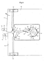
FIG. 4 is a plan view illustrating a first door being opened in the refrigerator employing the door opening device according to the first embodiment of the present invention; -
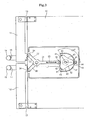
FIG. 5 is a plan view illustrating an actuating member of the door opening device returned to its initial position in the refrigerator employing the door opening device according to the first embodiment of the present invention; -
FIG. 6 is a plan view illustrating a second door being opened in the refrigerator employing the door opening device according to the first embodiment of the present invention; -
FIG. 7 is a block diagram illustrating control of operation of the door opening device according to the first embodiment of the present invention; -
FIG. 8 is a flowchart illustrating an initial malfunction diagnosing method of the door opening device according to the first embodiment of the present invention; -
FIG. 9 is a flowchart illustrating a control method of a door opening device according to a second embodiment of the present invention; -
FIG. 10 is a block diagram illustrating control of operation of a door opening device according to a third embodiment of the present invention; and -
FIG. 11 is a flowchart illustrating a control method of the door opening device according to the third embodiment of the present invention. - Reference will now be made in detail to the embodiments, examples of which are illustrated in the accompanying drawings, wherein like reference numerals refer to the like elements throughout. The embodiments are described below to explain the present invention by referring to the figures.
-
FIG. 1 is a perspective view illustrating a refrigerator employing a door opening device according to a first embodiment of the present invention. The refrigerator includes a main body which is partitioned into a first compartment (not shown) and a second compartment (not shown). To a front side of themain body 10, afirst door 11 and asecond door 12 are installed on sides of themain body 10 to open the first and second compartments, respectively. Generally, in the refrigerator, the first compartment forms a freezer compartment and the second compartment forms a refrigerator compartment. The first andsecond doors main body 10 to be pivoted byhinges 13 at respective upper and lower sides. Therespective doors handles - A
door opening device 20 is installed to an upper side of themain body 10. Thedoor opening device 20 pushes the upper sides of the first andsecond doors respective doors -
FIGS. 2 to 6 illustrate thedoor opening device 20 according to the first embodiment of the present invention, andFIG. 7 is a block diagram illustrating operation of thedoor opening device 20. - The
door opening device 20, as illustrated inFIGS. 2 and3 , includes an actuatingmember 30 to selectively open thedoors rotation cam 40 to rotate the actuatingmember 30 for the opening of thedoors motor 50 to rotate therotation cam 40 forward and in reverse. Thedoor opening device 20 further includes acam cover 52 to accommodate therotation cam 40 and anupper cover 21 to cover the upper side of the device. - The
rotation cam 40 includes threeprotrusions 41 to contact and rotate the actuatingmember 30 and threespacing portions 42 spaced apart from the actuatingmember 30. Therespective protrusions 41 andspacing portions 42 are alternately disposed in the rotation direction, and theprotrusions 41 are arranged every 120 degrees. Therespective protrusions 41 have a convex curved shape and therespective spacing portions 42 have a concave curved shape. - In this embodiment, although the numbers of the
protrusions 41 and thespacing portions 42 are, for example, three, different numbers of theprotrusions 41 and thespacing portions 42 can be utilized so long as adequate performance can be carried out. - The cam cover 52 to accommodate the
rotation cam 40 is fixed to the upper side of the refrigeratormain body 10 by fastening fixingscrews 53, and the drivingmotor 50 is fixed to the upper side of thecam cover 52. Theshaft 51 of the drivingmotor 50 penetrates thecam cover 52 and extends into thecam cover 52 to be coupled with therotation cam 40. Thus, therotation cam 40 rotates within thecam cover 52 during the operation of the drivingmotor 50. - The actuating
member 30 is coupled to the upper side of themain body 10 in front of therotation cam 40. For the coupling, themain body 10, as illustrated inFIG. 2 , includes a supportingshaft 23 provided on the upper side. Afastening screw 24 is fastened to the supportingshaft 23 to prevent the actuatingmember 30 from being separated after the coupling of the actuatingmember 30. - The actuating
member 30, as illustrated inFIG. 3 , includes a first extendingpart 31 extended from a center of rotation to therotation cam 40, a second extendingpart 32 extended inward from the center of rotation, and a third extendingpart 33 extended from the center of rotation to the inside of thesecond door 12. The actuatingmember 30 has a "Y"-shape. The first extendingpart 31 of the actuatingmember 30 contacts theprotrusions 41 of therotation cam 40 at its end, and has a length long enough to be spaced apart from the spacingportions 42 of therotation cam 40. Moreover, a distance L1 from an end of the first extendingpart 31 of the actuatingmember 30 to the center of rotation is longer than a distance L2 from ends of the second and third extendingparts FIGS. 4 and6 , such that the second extendingpart 32 or the third extendingpart 33 presses the inner surface of the first orsecond doors second doors rotation cam 40 rotates the first extendingpart 31 of the actuatingmember 30 with a small force. - The ends of the first, second, and third extending
parts member 30 are installed withrollers 34, respectively. This is to prevent friction between the first extendingpart 31 and therotation cam 40 and friction between the second and third extendingparts second doors door opening device 20 is driven. The first extendingpart 31 of the actuatingmember 30 is installed with areturn spring 25 to return the actuatingmember 30 to an initial position after opening the doors. - The
return spring 25 includes an end connected to the first extendingpart 31 and the other end connected to the upper side of themain body 10 to provide an elastic returning force to the first extendingpart 31. Although a coiltype return spring 25 is depicted as a device to return the actuating member in the drawing, the device may be an elastic member such as a torsion spring, spiral spring, rubber, or the like. - As such, since the actuating
member 30 receives the elasticity of thereturn spring 25, the actuatingmember 30, as illustrated inFIG. 3 , returns to the initial position. Moreover, in the initial state, the end of the first extendingpart 31 is positioned at one of thespacing portions 42 of therotation cam 40 and the drivingmotor 50 is stopped when positions of the spacingportion 42 and the first extendingpart 31 are the same. - To this end, the
door opening device 20 includes aposition detecting unit 110 to detect a rotation position of therotation cam 40 to control the drivingmotor 50. Theposition detecting unit 110 includesmagnets 43 disposed at leading edges of theprotrusions 41 of therotation cam 40 andposition detecting sensor 44 fixed to the outer cam cover 52 to detect themagnets 43. - The
position detecting sensor 44 may be a conventional reed switch, in this embodiment, as an example, the reed switch is turned on when theposition detecting sensor 44 faces one of themagnets 43 of theprotrusions 41, and is turned off when theposition detecting sensor 44 faces one of thespacing portions 42, and vice versa. - Meanwhile, the
position detecting unit 110 is not limited to the above-description, but may be a photo sensor to detect the positions of theprotrusions 41, or a limit switch to detect the position by contacting theprotrusions 41. - As illustrated in
FIGS. 1 and2 , theupper cover 21 is spaced apart from and covers the actuatingmember 30 and the upper side of the drivingmotor 50, and fixed to the upper side of themain body 10 by plural fixing screws 22. - The
door opening device 20 includesswitches handles second doors switches handles motor 50. - Operation of the
door opening device 20 will be described as follows. - As illustrated in
FIG. 3 , if thehandles second doors motor 50 does not work. Thus, the initial state is maintained. In other words, the first extendingpart 31 of the actuatingmember 30 is positioned at the central position of one of thespacing portions 42 of therotation cam 40. - As illustrated in
FIG. 4 , if the user holds or pulls thehandle 14 of thefirst door 11 to open thefirst door 11, theswitch 16 is activated to drive the drivingmotor 50. At this time, since therotation cam 40 rotates forward (clockwise) due to the drivingmotor 50 and one of theprotrusions 41 pushes the first extendingpart 31 of the actuatingmember 30, the actuatingmember 30 rotates counterclockwise. Thus, the second extendingpart 32 pushes the inner side of thedoor 11, resulting in easy opening of thefirst door 11. As illustrated inFIG. 6 , when therotation cam 40 rotates by 120 degrees clockwise and theposition detecting sensor 44 detects themagnets 43 disposed to theprotrusions 41, the drivingmotor 50 is stopped. In this state, since therotation cam 40 has been rotated by 120 degrees, this state is the same as the initial state. On the other hand, the actuatingmember 30 returns to the initial state due to the elasticity of thereturn spring 25 when the pressure of the first extendingpart 31 by theprotrusions 41 of therotation cam 40 is released. As such, since thedoor opening device 20 can open the doors only by the rotation of the drivingmotor 50 for a predetermined section in one direction and returns to the initial state, the drivingmotor 50 can be driven a minimal number of times. Thus, the lifespan of the drivingmotor 50 and its related components can be prolonged. - As illustrated in
FIG. 6 , when the user holds or pulls thehandles 15 of thesecond door 12 to open thesecond door 12, theswitch 17 is activated to drive the drivingmotor 50 in reverse. At this time, since therotation cam 40 rotates counterclockwise in reverse due to the drivingmotor 50 and one of theprotrusions 41 pushes the first extendingpart 31 of the actuatingmember 30, the actuating member rotates clockwise. Thus, in this case, the third extendingpart 33 pushes the inner side of thesecond door 12 to open thesecond door 12. In this case, the third extendingpart 33 pushes the inner side of thesecond door 12 to open thesecond door 12. After opening thesecond door 12, therotation cam 40 rotates by 120 degrees and is stopped, and the actuatingmember 30 returns to the initial state due to the elasticity of thereturn spring 25. As such, since the drivingmotor 50 rotates once in any one direction to sufficiently open therespective doors motor 50 can be minimized. - In a case when the first and
second doors doors motor 50. Thus, in comparison to the conventional art, the time of operation of the drivingmotor 50 can be significantly reduced as well and the twodoors - The operation of the
door opening device 20, as illustrated in the block diagram ofFIG. 7 , is performed as follows. When door opening signals are inputted via theswitches controller 100 transmits a signal to control the drivingmotor 50 to amotor driving unit 150 in accordance with a program stored in amemory 130 using information transmitted from theposition detecting unit 110 and atimer 140. - Moreover, the
controller 100 determines whether the drivingmotor 50 is driven or not, using the information transmitted from adoor opening sensor 120 to detect whether the twodoors - Meanwhile, the
controller 100 determines thedoor opening device 20 is malfunctioning or not in an initial state when power is supplied, or during operation of thedoor opening device 20, and transmits a control signal to indicate the malfunction to adisplay 160 when thedoor opening device 20 is malfunctioning. -
FIG. 8 is a flowchart illustrating an initial malfunction diagnosing method of thedoor opening device 20 according to the first embodiment of the present invention. - When power is supplied to the refrigerator (S200), the
controller 100 transmits a signal to rotate the drivingmotor 50 clockwise for a first predetermined time to the motor driving unit 150 (S210). The reason that this operation is performed will be described later. - When operation S210 is completed, the
controller 100 continues to rotate the driving motor and operates the timer 140 (S220), and determines whether rotation time T of the drivingmotor 50 exceeds a second predetermined time (S230). - If the rotation time T of the driving
motor 50 does not exceed the second predetermined time in operation S230, thecontroller 100 determines whether theposition detecting sensor 44, the reed switch, is turned off. If not, the operation S230 is performed again. If it is determined to be turned off, thecontroller 100 continues to rotate the drivingmotor 50 forward (S240 and S250). - Meanwhile, if the rotation time T of the driving
motor 50 exceeds the second predetermined time while the off state of theposition detecting sensor 44 is not detected in operation S230, thecontroller 100 transmits a signal to indicate the malfunction of thedoor opening device 20 to thedisplay 160 and completes the control (S300). - If the operation S250 is completed, the
controller 100 activates the timer 140 (S260), any determines whether the rotation time T of the drivingmotor 50 exceeds a third predetermined time (S270). - If the rotation time T of the driving
motor 50 does not exceed the third predetermined time in the operation S270, thecontroller 100 determines whether theposition detecting sensor 44 is turned on. If not, thecontroller 100 performs the operation S270. If theposition detecting sensor 44 is turned on, thecontroller 100 determines a normal state of thedoor opening device 20 and stops the driving motor 50 (S280 and S290). - Meanwhile, if the rotation time T of the driving
motor 50 exceeds the third predetermined time while the turned on state of theposition detecting sensor 44 is not detected in operation S270, thecontroller 100 performs operation S300. - In this case, the second predetermined time and the third predetermined time are values that are obtained by experiment and stored in the
memory 130, and are determined by a maximum time for the state of theposition detecting sensor 44 to be changed from the turned on state to the turned off state or from the turned off state to the turned on state when thedoor opening device 20 is normal. - In this embodiment, the driving
motor 50 is stopped when the position detecting sensor (reed switch) 44 is turned on after opening thedoors motor 50 further rotates in the rotation direction due to inertia despite of a stopping signal and then stops in the off state. - Thus, if the driving
motor 50 stops at the position in the reverse rotation direction before power is supplied to the refrigerator in operation S200, since the off state is spontaneously changed to the on state and is detected when the diagnosis for the malfunction is performed in the forward rotation direction, as this embodiment, the reliable diagnosis for the malfunction cannot be performed. Therefore, in this embodiment, the operation S210 is performed such that the diagnosis for the malfunction is performed after the effect of the inertia. - In this case, the first predetermined time is a value obtained by experiment and is stored in the
memory 130, and a rotation time of considering the separation from the stopping position of the drivingmotor 50 occurring when thedoor opening device 20 is normal. - Meanwhile, although a case where the initial diagnosis of the malfunction is performed when the driving
motor 50 rotates forward is described in this embodiment, the drivingmotor 50 may rotate in either the forward or reverse direction. -
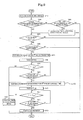
FIG. 9 is a flowchart illustrating a control method of adoor opening device 20 according to a second embodiment of the present invention, and since the configuration, the operation, and the control method of the refrigerator are similar to those of the first embodiment, the duplicated description will be omitted. - When a door opening signal is input via the
switches 16 and 17 (S410), thecontroller 100 determines which of doors corresponds to the door opening signal (S420). - If the door opening signal is to open any one of the two
doors controller 100 determines whether the drivingmotor 50 is stopped or not (S450). If the stopped state of the drivingmotor 50 is determined as a result of the determination in operation S450, thecontroller 100 determines whether thedoor controller 100 rotates the drivingmotor 50 in the direction where thedoor - At this time, whether the
doors door opening sensor 120, and since the first predetermined time is identical to that of the initial diagnosis, a duplicated description will be omitted. - Meanwhile, if door opening signals of opening both of the two
doors controller 100 determines whether the two signals are sequentially inputted (S430). If sequentially inputted, thecontroller 100 accepts only a first inputted door opening signal to perform the operation S450 and excludes the other door opening signal (S440). - If two door opening signals are inputted simultaneously in the operation S430, the
controller 100 does not accept both of the signals. However, this case may be implemented in another embodiment in which it is possible to accept a door opening signal of opening any one of the two doors, basically preset in thememory 130 and the return to the operation S450 is identical to the above case. - Moreover, as a result of the determination in the operation S450, if not stopped, the
controller 100 determines thedoor opening device 20 is being driven and does not accept the door opening signal. - Further, as a result of the determination in the operation S460, if the
corresponding door controller 100 determines the signal is undesired and does not accept the currently inputted door opening signal. - Meanwhile, when operation S470 is completed, the
controller 100 keeps the drivingmotor 50 rotating and activates the timer 140 (S480), and determines whether the rotation time T of the drivingmotor 50 exceeds the second predetermined time (S490). - If the rotation time T of the driving
motor 50 does not exceed the second predetermined time in operation S490, thecontroller 100 determines whether theposition detecting sensor 44, i.e., the reed switch, is turned off or on. If not off, thecontroller 100 performs the operation S490 again. If off, thecontroller 100 keeps the drivingmotor 50 rotating for the third predetermined time regardless of turning on or off of the position detecting sensor 44 (S500 and S510). - At this time, the reason for keeping the driving
motor 50 rotating for the third predetermined time is to prevent the drivingmotor 50 from malfunctioning due to chattering. - The chattering phenomenon occurs when electric contacts contact each other and are separated from each other abnormally for a very short time due to mechanical vibration. In this embodiment, if the off state of the
position detecting sensor 44 is spontaneously changed to the on state due to the chattering, since thecontroller 100 may determine the door is opened by the rotation of the drivingmotor 50 even though the drivingmotor 50 does not actually rotate to open thedoors controller 100 performs operation S510 in order to prevent this phenomenon. - Meanwhile, if the rotation time T of the driving
motor 50 exceeds the second predetermined time without detection of the turned off state of theposition detecting sensor 44 in the operation S490, thecontroller 100 transmits a signal indicating the malfunction of thedoor opening device 20 to thedisplay 160 and completes the control (S560). - When the operation S510 is completed, the
controller 100 activates the timer 140 (S520) and determines whether the rotation time T of the drivingmotor 50 exceeds a fourth predetermined time (S530). - If the rotation time T of the driving
motor 50 does not exceed the fourth predetermined time in the operation S530, thecontroller 100 determines whether theposition detecting sensor 44 is turned on. If not turned on, thecontroller 100 performs the operation S530 again, and if turned on, thecontroller 100 determines thedoor - Meanwhile, if the rotation time T of the driving
motor 50 exceeds the fourth predetermined time without recognizing the turned on state of theposition detecting sensor 44 in the operation S530, thecontroller 100 performs the operation S560. - In this case, the second predetermined time and the fourth predetermined time are values obtained by experiment and are stored in the
memory 130, and are determined by a maximum time taken for the state of theposition detecting sensor 44 to be changed from the turned on state to the turned off state or from the turned off state to the turned on state when thedoor opening device 20 is normal. -
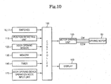
FIG. 10 is a block diagram illustrating control of operation of a door opening device according to a third embodiment of the present invention, and since the configuration and the operation of the refrigerator are similar to those of the first embodiment, the duplicated description will be omitted. Moreover, in the block diagram ofFIG. 10 , identical reference numerals are assigned to the same components as in the first embodiment. - As illustrated in
FIG. 10 , when door opening signals are inputted via theswitches controller 100 transmits a signal to control the drivingmotor 50 to themotor driving unit 150 in accordance with a program stored in amemory 130 using information transmitted from theposition detecting unit 110 and thetimer 140. - Moreover, the
controller 100 determines whether the drivingmotor 50 is driven or not using the information transmitted from adoor opening sensor 120 to detect whether the twodoors - Meanwhile, the
controller 100 determines frequency of the opening of the doors due to thedoor opening device 20 to determine whether a locking function is to be set for the protection of thedoor opening device 20, and as a result of the determination, transmits a control signal indicating whether thedoor opening device 20 is in a locking mode that the locking function is set or in a release mode that the locking function is released to thedisplay 160. - Moreover, the
controller 100 first performs an inputted operation mode when a control signal for which the user selects one operation mode of the locking mode and a driving mode of thedoor opening device 20 is inputted to an operationmode input unit 170. -
FIG. 11 is a flowchart illustrating a control method of thedoor opening device 20 according to the third embodiment of the present invention. - The
controller 100 determines whether thedoor opening device 20 is in the locking mode (S600), and if the locking mode, activates thetimer 140 to determine whether the door opening signal is inputted for the first predetermined time (S610 and S620). - If the door opening signal is inputted for the first predetermined time Tset1 as a result of the determination in the operation S620, the
controller 100 performs the operation S610 again, and if not inputted, releases the locking mode of thedoor opening device 20 to the operation mode and displays the mode change on the display 160 (S630). - In this case, the first predetermined time Tset1 is a value obtained by experiment and is stored in the
memory 130, and is determined by a time required to protect thedoor opening device 20 from excessive operation. - If the operation S630 is completed, the
controller 100 determines whether a power off signal for the refrigerator is inputted (S640), completes the control when the power off signal is inputted, and performs the operation S600 again when the power off signal is not inputted. - Meanwhile, if the
door opening device 20 is not in the locking mode in the operation S600, thecontroller 100 drives thedoor opening device 20 in order to open thedoor switches doors 11 and 12 (S650 to S700). - If the
doors controller 100 performs the operation S650 to determine the frequency of the opening of thedoors doors controller 100 changes the mode of thedoor opening device 20 to the locking mode in order to protect thedoor opening device 20 and displays the mode change on the display 160 (S710). - In this case, the second predetermined time Tset2 and the predetermined times Nset are values obtained by experiment and are stored in the
memory 130, and are determined by values determining that thedoor opening device 20 is being excessively driven. - If the operation S710 is completed, the
controller 100 determines whether the power off signal of the refrigerator is inputted (S640). If inputted, the control is completed, and if not, the operation S600 is performed again. - The above-described control method relates to a protecting program of the
door opening device 20 applied in accordance with the operation frequency of thedoor opening device 20, and as described above, if the user inputs a control signal of selecting any one operation mode of the locking mode and the driving mode of thedoor opening device 20 to the operationmode input unit 170, the inputted operation mode is first performed. - As described above, although the refrigerator and the control method thereof are described to be implemented by the first to third embodiments independently, it could be understood that if necessary, the refrigerator and the control method thereof can be implemented by combining features of the plural embodiments.
- As described above, the door opening device of a refrigerator according to the embodiments of the present invention can open the doors using only the rotation of the driving motor in one direction by a predetermined section, can return to the initial state without the reverse rotation of the driving motor after the opening of the doors, and can open the two doors using only the forward and reverse rotation of the driving motor even when the first and second doors are sequentially opened. Therefore, the control of the driving motor can be minimized so that life spans of the driving motor and the related components can be prolonged.
- Moreover, according to the refrigerator and the control method thereof of the embodiments of the present invention, the position of the rotation cam is detected at the initial state when the power is supplied or during the operation to determine whether the door opening device is malfunctioning. In the early time when the position of the rotation cam is detected, the driving motor is rotated by force so that the malfunction of the driving motor due to the chattering can be prevented.
- Further, according to the refrigerator and the control method thereof of the present invention, the frequency of the opening of the doors by the door opening signal is determined and the door opening device is driven in the locking mode or the release mode in accordance with the determination so that the door opening device can be prevented from being damaged due to the excessive operation.
- Although a few embodiments have been shown and described, it would be appreciated by those skilled in the art that changes may be made in these embodiments without departing from the invention, the scope of which is defined in the claims.
Claims (34)
- A refrigerator comprising:a main body (10) defining first and second compartments therein;first and second doors (11, 12) to respectively open and close the first and second compartments;a door opening device (20) comprising:a switch (16, 17) to input a plurality of door opening signals respectively corresponding to the first and second doors (11, 12) to respectively open the first and second doors (11, 12),an actuating member (30) to rotate to selectively open the first and second doors (11, 12),a rotation cam (40) including a plurality of protrusions (41) to contact and rotate the actuating member (30) and a plurality of spacing portions (42) spaced apart from the actuating member (30), the protrusions (41) and the spacing portions (42) being alternately disposed in a rotation direction,a driving motor (50) to rotate the rotation cam (40) forward and in reverse, anda return device (25) to return the actuating member (30) to an initial position after opening one of the first and second doors (11, 12);a position detecting unit (110) to detect a rotation position of the rotation cam (40) to control the driving motor (50);a door opening sensor (120) to detect whether the first and second doors (11, 12) are opened; anda controller (100) to control the door opening device (20) in accordance with the door opening signals when the door opening signals are inputted to the switch (16, 17), to transmit a signal for controlling the driving motor (50) in accordance with a program stored in a memory (130) using information transmitted from the position detecting unit (110) and a timer (140), and to determine whether the driving motor (50) is driven or not using information transmitted from the door opening sensor (120) to detect whether the first and second doors (11, 12) are opened or not, when the door opening signals are input;the refrigerator being characterized in that
the controller (100) is further configured to determine a malfunction of the door opening device (20) in an initial state when power is supplied or during operation of the door opening device (20) and to transmit a control signal indicating the malfunction. - The refrigerator according to claim 1, wherein the controller (100) accepts only a first inputted one of the door opening signals when the plurality of the door opening signals for the first and second doors (11, 12) are inputted, and rotates the driving motor (50) in a first direction in order to open the door corresponding to the accepted door opening signal.
- The refrigerator according to claim 2, wherein the controller (100) disregards the door opening signals for the first and second doors (11, 12) when the door opening signals are inputted simultaneously.
- The refrigerator according to claim 2, wherein the controller (100) accepts only the door opening signal corresponding to a preset one of the first and second doors (11, 12) when the door opening signals are inputted simultaneously.
- The refrigerator according to claim 4, wherein, when the accepted door opening signal is inputted during the rotation of the driving motor (50), the controller (100) disregards the inputted door opening signal.
- The refrigerator according to claim 5, wherein, the controller (100) disregards the inputted door opening signal when the door opening sensor (120) detects the door corresponding to the inputted door opening signal is open.
- The refrigerator according to claim 6, wherein:the position detecting unit (110) having a portion contacting the protrusions (41) during the rotation of the actuating member (30) and being positioned opposite a first one of the protrusions (41) of the rotation cam (40) at the initial state when the door opening signal is not accepted, andthe controller (100) determines the rotation position of the rotation cam (40) detected by the position detecting unit when any one of the door opening signals is accepted, and rotates the driving motor (50) in the first direction such that the rotation cam (40) rotates until the protrusion (41) adjacent the first one of the protrusions (41) is opposite the position detecting unit.
- The refrigerator according to claim 7, wherein the position detecting unit (110) comprises magnets disposed at leading edges of the respective protrusions and a detecting sensor (44) installed to an outer side of the rotation cam (40) to detect the magnets.
- The refrigerator according to claim 8, further comprising a display (160) to display a malfunction of the door opening device (20), wherein the controller (100) determines the door opening device (20) has malfunctioned when the protrusion (41) adjacent to the first protrusion (41) is not detected within a first predetermined time and controls the display (160) to display the malfunction.
- The refrigerator according to claim 9, wherein the controller (100) rotates the driving motor (50) for a second predetermined time before detecting the rotation position of the rotation cam (40) when the door opening signals are accepted.
- The refrigerator according to claim 10, wherein the controller (100) disregards the rotation position of the rotation cam (40) for a third predetermined time and rotates the driving motor (50) in the first direction when the spacing portions (42) are detected during the rotation of the driving motor (50).
- The refrigerator according to claim 11, wherein, when electric power is supplied to the refrigerator, the controller (100) rotates the driving motor (50) in either the first or second direction until the protrusion (41) adjacent to the first protrusion (41) is detected for an initial malfunction diagnosis.
- The refrigerator according to claim 12, wherein, when the protrusion (41) adjacent the first protrusion (41) is not detected within the first predetermined time during the initial malfunction diagnosis, the controller (100) determines the door opening device (20) malfunctioned and controls the display (160) to display the malfunction.
- The refrigerator according to claim 13, wherein the controller (100), in the initial malfunction diagnosis, first rotates the driving motor (50) for the second predetermined time before detecting the rotation position of the rotation cam (50).
- The refrigerator according to claim 14, wherein the controller (100) determines a frequency of the opening of the doors (11, 12) due to the door opening signals inputted to the switches (16, 17) during the control of the door opening device (20), and when the frequency is greater than a fourth predetermined time, the controller (100) performs a locking mode of the door opening device (20) that the door opening device (20) is not operated even when the door opening signals are inputted.
- The refrigerator according to claim 15, wherein, when the door opening signals are not inputted for a fifth predetermined time while the locking mode of the door opening device (20) is performed, the controller (100) performs a driving mode of the door opening device (20) that the locking mode of the door opening device (20) is released and the door opening device (20) is driven in accordance with an inputted door opening signal.
- The refrigerator according to claim 16, further comprising an input unit (170) to input any one operation mode of the locking mode and the driving mode of the door opening device (20), wherein, when the operation mode is inputted to the input unit (170) by a control signal of a user, the controller (100) firstly performs the inputted operation mode regardless of the frequency that the doors (11, 12) are opened by the door opening signals.
- The refrigerator according to claim 17, wherein, when the locking mode or the driving mode of the door opening device (20) is performed, the controller (100) controls the display (160) to display the performing operation mode.
- A method of controlling a refrigerator comprising:a first door (11) and a second door (12) to respectively open and close the first and second compartments,a door opening device (20) comprising:a switch (16, 17) to input a plurality of door opening signals respectively corresponding to the first and second doors (11, 12) to respectively open the first and second doors (11, 12),an actuating member (30) to rotate to selectively open the first and second doors (11, 12),a rotation cam (40) including a plurality of protrusions (41) to contact and rotate the actuating member (30) and a plurality of spacing portions (42) spaced apart from the actuating member (30), the protrusions (41) and the spacing portions (42) being alternately disposed in a rotation direction,a driving motor (50) to rotate the rotation cam (40) forward and in reverse,a return device (25) to return the actuating member (30) to an initial position after opening one of the first and second doors (11, 12),a position detecting unit (110) to detect a rotation position of the rotation cam (40) to control the driving motor (50); anda door opening sensor (120) to detect whether the first and second doors (11, 12) are opened;the method comprising:controlling the door opening device (20) in accordance with the door opening signals when the door opening signals are inputted to the switch (16, 17),transmitting a signal for controlling the driving motor (50) in accordance with a program stored in a memory (130) using information transmitted from the position detecting unit (110) and a timer (140), anddetermining whether the driving motor (50) is driven or not using information transmitted from the door opening sensor (120) to detect whether the first and second doors (11, 12) are opened or not, when the door opening signals are input;the method further characterized indetermining a malfunction of the door opening device (20) in an initial state when power is supplied or during operation of the door opening device (20), andtransmitting a control signal indicating the malfunction.
- The method of controlling a refrigerator according to claim 19, wherein, when the plurality of the door opening signals for the first and second doors (11, 12) are inputted, the method further comprises accepting only a first inputted one of the door opening signals and rotating the driving motor (50) in a first direction in order to open the door corresponding to the accepted door opening signal.
- The method of controlling a refrigerator according to claim 19, comprising disregarding the door opening signals for the two doors or accepting only one of the door opening signals corresponding to a preset one of the two doors when the door opening signals are inputted simultaneously.
- The method of controlling a refrigerator according to claim 21, wherein, when the door opening signal is inputted during the rotation of the driving motor (50), the method further comprises disregarding the inputted door opening signal.
- The method of controlling a refrigerator according to claim 22, further comprising detecting whether a door corresponding to the inputted door opening signal is opened, and if the corresponding door is opened, the inputted door opening signal is disregarded.
- The method of controlling a refrigerator according to claim 23, wherein the door opening device (20) further comprises a position detecting sensor (44) to detect a position of the rotation cam (40), the position detecting sensor (44) being opposite a first one of the protrusions (41), when the door opening signal is accepted, method further comprises detecting the rotation position of the rotation cam (40), and the driving motor (50) is rotated in a first direction such that the rotation cam (40) rotates until a second one of the protrusions (41) is opposite the position detecting sensor (44), the second protrusion (41) being adjacent the first protrusion (41).
- The method of controlling a refrigerator according to claim 24, wherein, the position detecting unit (110) further comprises a detecting sensor (44), installed to an outer side of the rotation cam (40) the method further comprising detecting magnets disposed at leading edges of the respective protrusions (41).
- The method of controlling a refrigerator according to claim 25, wherein, when the second protrusion (41) is not detected within a first predetermined time the method further comprises determining that the door opening device (20) is malfunctioning and the malfunctioned state is displayed.
- The method of controlling a refrigerator according to claim 26, wherein, when the door opening signals are accepted, the method further comprises rotating the driving motor (50) for a second predetermined time before detecting the rotation position of the rotation cam (40).
- The method of controlling a refrigerator according to claim 27, wherein, when the spacing portions (42) are detected during the rotation of the driving motor (50), the method further comprises disregarding the rotation position of the rotation cam (40) for a third predetermined time and rotating the driving motor (50) in the first direction.
- The method of controlling a refrigerator according to claim 28, wherein, when electric power is supplied to the refrigerator, the method further comprises performing an initial malfunction diagnosis while rotating the driving motor (50) in any direction until the second protrusion (41) disposed next to a current position is detected.
- The method of controlling a refrigerator according to claim 29, wherein, when the second protrusion (41) is not detected within the first predetermined time during the initial malfunction diagnosis, the method further comprises determining that the door opening device (20) is malfunctioning and the display (160) displays the malfunction.
- The method of controlling a refrigerator according to claim 30, wherein the method further comprises rotating in the performing the initial malfunction diagnosis, the driving motor (50) is for the second predetermined time before detecting the rotation position of the rotation cam (40).
- The method of controlling a refrigerator according to claim 31, wherein, when the frequency of the opening of the doors due to the door opening signals is determined during the control of the door opening device (20), and the frequency is greater than a predetermined times for a fourth predetermined time, the method comprises not operating a locking mode of the door opening device (20) even when the door opening signals are inputted.
- The method of controlling a refrigerator according to claim 32, wherein, when the door opening signals are not inputted for a fifth predetermined time while the locking mode of the door opening device (20) is performed, the method comprises performing a driving mode of the door opening device (20) that the locking mode of the door opening device (20) is released and the door opening device (20) is driven in accordance with an inputted door opening signal.
- The method of controlling a refrigerator according to claim 33, wherein, when the operation mode is inputted by a control signal of a user, the method comprises performing the inputted operation mode is firstly performed regardless of the frequency that the doors (11, 12) are opened by the door opening signals.
Applications Claiming Priority (2)
| Application Number | Priority Date | Filing Date | Title |
|---|---|---|---|
| KR1020060124758A KR100794603B1 (en) | 2006-12-08 | 2006-12-08 | Refrigerator and its control method |
| KR1020060125671A KR101034202B1 (en) | 2006-12-11 | 2006-12-11 | Refrigerator and its control method |
Publications (3)
| Publication Number | Publication Date |
|---|---|
| EP1930675A2 EP1930675A2 (en) | 2008-06-11 |
| EP1930675A3 EP1930675A3 (en) | 2014-04-30 |
| EP1930675B1 true EP1930675B1 (en) | 2016-11-09 |
Family
ID=39226729
Family Applications (1)
| Application Number | Title | Priority Date | Filing Date |
|---|---|---|---|
| EP07121897.8A Ceased EP1930675B1 (en) | 2006-12-08 | 2007-11-29 | Refrigerator and control method thereof |
Country Status (2)
| Country | Link |
|---|---|
| US (1) | US8099970B2 (en) |
| EP (1) | EP1930675B1 (en) |
Families Citing this family (28)
| Publication number | Priority date | Publication date | Assignee | Title |
|---|---|---|---|---|
| KR101291206B1 (en) * | 2007-02-26 | 2013-07-31 | 삼성전자주식회사 | Refrigerator |
| KR20100064022A (en) * | 2008-12-04 | 2010-06-14 | 삼성전자주식회사 | Refrigerator and control method thereof |
| KR20110022849A (en) * | 2009-08-28 | 2011-03-08 | 삼성전자주식회사 | Refrigerator |
| KR101639435B1 (en) * | 2009-10-13 | 2016-07-13 | 엘지전자 주식회사 | Refrigerator |
| KR101658668B1 (en) * | 2009-10-13 | 2016-09-21 | 엘지전자 주식회사 | Opening method of refrigerator door |
| IT1396490B1 (en) * | 2009-12-10 | 2012-12-14 | Blasi De | REFRIGERATED SHOWCASE FOR ICE CREAMS, REDUCED ENERGY CONSUMPTION AND HIGH PROTECTION OF THE PRODUCTS CONTAINED |
| KR20110068765A (en) | 2009-12-15 | 2011-06-22 | 엘지전자 주식회사 | Control method of clothes processing device and clothes processing device |
| TR200909883A2 (en) * | 2009-12-29 | 2011-07-21 | Bsh Ev Aletleri̇ San. Ve Ti̇c. A.Ş. | Cooling device with a door opening aid. |
| TR200909884A2 (en) * | 2009-12-29 | 2011-07-21 | Bsh Ev Aletleri̇ San. Ve Ti̇c. A.Ş. | Cooling device with a door opening aid |
| DE102011084825A1 (en) * | 2011-10-19 | 2013-04-25 | BSH Bosch und Siemens Hausgeräte GmbH | The refrigerator |
| US9097052B2 (en) * | 2011-12-06 | 2015-08-04 | Hefei Midea Refrigerator Co., Ltd. | Refrigerator |
| DE102012202392B4 (en) | 2012-02-16 | 2015-08-27 | Schott Ag | refrigeration cabinets |
| KR101618552B1 (en) * | 2014-09-05 | 2016-05-09 | 엘지전자 주식회사 | Closing and opening device for refrigerator door and control method of the same |
| KR101644438B1 (en) * | 2014-11-20 | 2016-08-01 | 엘지전자 주식회사 | Refrigerator |
| JP6502390B2 (en) * | 2015-07-30 | 2019-04-17 | エルジー エレクトロニクス インコーポレイティド | refrigerator |
| US10684063B2 (en) | 2015-12-28 | 2020-06-16 | Whirlpool Corporation | Easy open drawer/door with rotating handle |
| US10995536B2 (en) * | 2017-01-03 | 2021-05-04 | Samsung Electronics Co., Ltd. | Refrigerator |
| JP6894967B2 (en) * | 2017-02-16 | 2021-06-30 | シャープ株式会社 | Door opening device and refrigerator |
| KR102490433B1 (en) * | 2017-04-24 | 2023-01-19 | 엘지전자 주식회사 | Refrigerator |
| WO2018220872A1 (en) * | 2017-05-30 | 2018-12-06 | シャープ株式会社 | Door opening device and refrigerator |
| TR201902445A2 (en) * | 2019-02-19 | 2020-09-21 | Vestel Beyaz Esya Sanayi Ve Ticaret Anonim Sirketi | Automatic door opening system and related method. |
| CN113048702A (en) * | 2019-12-26 | 2021-06-29 | 佛山市云米电器科技有限公司 | Automatic door opening control method and automatic door opening device for household appliances |
| CN113048711A (en) * | 2019-12-26 | 2021-06-29 | 佛山市云米电器科技有限公司 | Automatic door opening control method and automatic door opening device for household electrical appliance |
| CN112065210A (en) * | 2020-08-26 | 2020-12-11 | 珠海格力电器股份有限公司 | Intelligent opening and closing control method and device and electrical equipment |
| CN113156877A (en) * | 2021-05-31 | 2021-07-23 | 苏州调皮鱼电子科技有限公司 | Low-cost cold chain monitored control system |
| CN114646181B (en) * | 2022-03-11 | 2024-06-28 | 海信冰箱有限公司 | Auxiliary door closing control method for refrigerator and refrigerator |
| EP4477978A4 (en) * | 2022-08-11 | 2025-07-16 | Samsung Electronics Co Ltd | Refrigerator and control method thereof |
| EP4556824A4 (en) * | 2022-12-28 | 2025-12-10 | Samsung Electronics Co Ltd | REFRIGERATOR |
Family Cites Families (8)
| Publication number | Priority date | Publication date | Assignee | Title |
|---|---|---|---|---|
| KR100247727B1 (en) * | 1997-09-08 | 2000-04-01 | 전주범 | Door opening apparatus for refrigerator |
| US6386599B1 (en) * | 1999-08-12 | 2002-05-14 | John Phillip Chevalier | Latch arrangement for automotive door |
| JP3440033B2 (en) * | 1999-07-22 | 2003-08-25 | 松下冷機株式会社 | Refrigerator door opening device |
| WO2004049088A1 (en) * | 2002-11-22 | 2004-06-10 | Radar Hvac-Refrigeration Inc. | Refrigeration monitor |
| US7319407B2 (en) * | 2003-12-19 | 2008-01-15 | Lg Electronics Inc. | Display unit for refrigerator |
| KR100597754B1 (en) * | 2004-10-29 | 2006-07-07 | 삼성전자주식회사 | How to open the door of refrigerator and freezer |
| KR100675795B1 (en) | 2004-11-05 | 2007-02-02 | 삼성전자주식회사 | How to open the doors of double door refrigerators and double door refrigerators |
| US7819488B2 (en) * | 2006-10-09 | 2010-10-26 | Samsung Electronics Co., Ltd. | Door opening device and refrigerator having the same |
-
2007
- 2007-11-15 US US11/984,313 patent/US8099970B2/en active Active
- 2007-11-29 EP EP07121897.8A patent/EP1930675B1/en not_active Ceased
Also Published As
| Publication number | Publication date |
|---|---|
| EP1930675A3 (en) | 2014-04-30 |
| US8099970B2 (en) | 2012-01-24 |
| US20080134698A1 (en) | 2008-06-12 |
| EP1930675A2 (en) | 2008-06-11 |
Similar Documents
| Publication | Publication Date | Title |
|---|---|---|
| EP1930675A2 (en) | Refrigerator and control method thereof | |
| CN100580348C (en) | Refrigerator and method for controlling the same | |
| EP2194347B1 (en) | Refrigerator and method of controlling the same | |
| EP1911921B1 (en) | Door opening device and refrigerator having the same | |
| EP2169157B1 (en) | Door lock apparatus | |
| US6557910B2 (en) | Door lock drive unit | |
| EP2787311B1 (en) | Door assembly and refrigerator having the same | |
| KR100404982B1 (en) | Motor valve and refrigerator | |
| WO1999047887A1 (en) | Rotation angle detector | |
| KR101034202B1 (en) | Refrigerator and its control method | |
| KR20080105220A (en) | Refrigerator | |
| KR100276738B1 (en) | Apparatus and method for controlling ice discharge from refrigerator | |
| JP2006046741A (en) | refrigerator | |
| EP2781861B1 (en) | Refrigerator with an ice dispenser | |
| US6779352B2 (en) | Refrigerator and method of controlling the same | |
| AU2018318603B2 (en) | Refrigerator and control method thereof | |
| KR20080032587A (en) | Door opening device and refrigerator with same | |
| EP2187152B1 (en) | Ice dispensing technology | |
| KR101339924B1 (en) | Door opening device and refrigerator having the same | |
| KR0155972B1 (en) | Right and left opening and closing device of door | |
| CN220355859U (en) | Door components and refrigeration equipment for refrigeration equipment | |
| KR20050028362A (en) | Ice-maker in refrigerator | |
| JPH11201609A (en) | Electric refrigerator control method and device | |
| JP2001165538A (en) | Driving device of automatic ice making machine | |
| KR100783963B1 (en) | Opening and closing control method of sliding door |
Legal Events
| Date | Code | Title | Description |
|---|---|---|---|
| PUAI | Public reference made under article 153(3) epc to a published international application that has entered the european phase |
Free format text: ORIGINAL CODE: 0009012 |
|
| AK | Designated contracting states |
Kind code of ref document: A2 Designated state(s): AT BE BG CH CY CZ DE DK EE ES FI FR GB GR HU IE IS IT LI LT LU LV MC MT NL PL PT RO SE SI SK TR |
|
| AX | Request for extension of the european patent |
Extension state: AL BA HR MK RS |
|
| RAP1 | Party data changed (applicant data changed or rights of an application transferred) |
Owner name: SAMSUNG ELECTRONICS CO., LTD. |
|
| PUAL | Search report despatched |
Free format text: ORIGINAL CODE: 0009013 |
|
| AK | Designated contracting states |
Kind code of ref document: A3 Designated state(s): AT BE BG CH CY CZ DE DK EE ES FI FR GB GR HU IE IS IT LI LT LU LV MC MT NL PL PT RO SE SI SK TR |
|
| AX | Request for extension of the european patent |
Extension state: AL BA HR MK RS |
|
| RIC1 | Information provided on ipc code assigned before grant |
Ipc: F25D 23/02 20060101AFI20140326BHEP |
|
| 17P | Request for examination filed |
Effective date: 20141021 |
|
| RBV | Designated contracting states (corrected) |
Designated state(s): AT BE BG CH CY CZ DE DK EE ES FI FR GB GR HU IE IS IT LI LT LU LV MC MT NL PL PT RO SE SI SK TR |
|
| AKX | Designation fees paid |
Designated state(s): DE FR GB |
|
| AXX | Extension fees paid |
Extension state: HR Extension state: MK Extension state: RS Extension state: AL Extension state: BA |
|
| 17Q | First examination report despatched |
Effective date: 20151027 |
|
| GRAP | Despatch of communication of intention to grant a patent |
Free format text: ORIGINAL CODE: EPIDOSNIGR1 |
|
| INTG | Intention to grant announced |
Effective date: 20160513 |
|
| GRAS | Grant fee paid |
Free format text: ORIGINAL CODE: EPIDOSNIGR3 |
|
| GRAA | (expected) grant |
Free format text: ORIGINAL CODE: 0009210 |
|
| AK | Designated contracting states |
Kind code of ref document: B1 Designated state(s): DE FR GB |
|
| REG | Reference to a national code |
Ref country code: GB Ref legal event code: FG4D |
|
| REG | Reference to a national code |
Ref country code: FR Ref legal event code: PLFP Year of fee payment: 10 |
|
| REG | Reference to a national code |
Ref country code: DE Ref legal event code: R096 Ref document number: 602007048628 Country of ref document: DE |
|
| REG | Reference to a national code |
Ref country code: DE Ref legal event code: R097 Ref document number: 602007048628 Country of ref document: DE |
|
| PLBE | No opposition filed within time limit |
Free format text: ORIGINAL CODE: 0009261 |
|
| STAA | Information on the status of an ep patent application or granted ep patent |
Free format text: STATUS: NO OPPOSITION FILED WITHIN TIME LIMIT |
|
| 26N | No opposition filed |
Effective date: 20170810 |
|
| REG | Reference to a national code |
Ref country code: FR Ref legal event code: PLFP Year of fee payment: 11 |
|
| REG | Reference to a national code |
Ref country code: FR Ref legal event code: PLFP Year of fee payment: 12 |
|
| PGFP | Annual fee paid to national office [announced via postgrant information from national office to epo] |
Ref country code: FR Payment date: 20211022 Year of fee payment: 15 |
|
| PGFP | Annual fee paid to national office [announced via postgrant information from national office to epo] |
Ref country code: GB Payment date: 20221020 Year of fee payment: 16 Ref country code: DE Payment date: 20220621 Year of fee payment: 16 |
|
| PG25 | Lapsed in a contracting state [announced via postgrant information from national office to epo] |
Ref country code: FR Free format text: LAPSE BECAUSE OF NON-PAYMENT OF DUE FEES Effective date: 20221130 |
|
| REG | Reference to a national code |
Ref country code: DE Ref legal event code: R119 Ref document number: 602007048628 Country of ref document: DE |
|
| GBPC | Gb: european patent ceased through non-payment of renewal fee |
Effective date: 20231129 |
|
| PG25 | Lapsed in a contracting state [announced via postgrant information from national office to epo] |
Ref country code: DE Free format text: LAPSE BECAUSE OF NON-PAYMENT OF DUE FEES Effective date: 20240601 |
|
| PG25 | Lapsed in a contracting state [announced via postgrant information from national office to epo] |
Ref country code: GB Free format text: LAPSE BECAUSE OF NON-PAYMENT OF DUE FEES Effective date: 20231129 |
|
| PG25 | Lapsed in a contracting state [announced via postgrant information from national office to epo] |
Ref country code: GB Free format text: LAPSE BECAUSE OF NON-PAYMENT OF DUE FEES Effective date: 20231129 Ref country code: DE Free format text: LAPSE BECAUSE OF NON-PAYMENT OF DUE FEES Effective date: 20240601 |