EP1930649A1 - Flashlight with LCD display - Google Patents
Flashlight with LCD display Download PDFInfo
- Publication number
- EP1930649A1 EP1930649A1 EP07020907A EP07020907A EP1930649A1 EP 1930649 A1 EP1930649 A1 EP 1930649A1 EP 07020907 A EP07020907 A EP 07020907A EP 07020907 A EP07020907 A EP 07020907A EP 1930649 A1 EP1930649 A1 EP 1930649A1
- Authority
- EP
- European Patent Office
- Prior art keywords
- light source
- main part
- lcd display
- control device
- batteries
- Prior art date
- Legal status (The legal status is an assumption and is not a legal conclusion. Google has not performed a legal analysis and makes no representation as to the accuracy of the status listed.)
- Withdrawn
Links
- 230000005611 electricity Effects 0.000 claims abstract description 18
- 238000005259 measurement Methods 0.000 claims abstract description 4
- 238000006243 chemical reaction Methods 0.000 claims description 2
- 238000010586 diagram Methods 0.000 description 3
- 238000005286 illumination Methods 0.000 description 3
Images


Classifications
-
- H—ELECTRICITY
- H05—ELECTRIC TECHNIQUES NOT OTHERWISE PROVIDED FOR
- H05B—ELECTRIC HEATING; ELECTRIC LIGHT SOURCES NOT OTHERWISE PROVIDED FOR; CIRCUIT ARRANGEMENTS FOR ELECTRIC LIGHT SOURCES, IN GENERAL
- H05B39/00—Circuit arrangements or apparatus for operating incandescent light sources
- H05B39/04—Controlling
- H05B39/041—Controlling the light-intensity of the source
- H05B39/044—Controlling the light-intensity of the source continuously
-
- H—ELECTRICITY
- H01—ELECTRIC ELEMENTS
- H01M—PROCESSES OR MEANS, e.g. BATTERIES, FOR THE DIRECT CONVERSION OF CHEMICAL ENERGY INTO ELECTRICAL ENERGY
- H01M10/00—Secondary cells; Manufacture thereof
- H01M10/42—Methods or arrangements for servicing or maintenance of secondary cells or secondary half-cells
- H01M10/48—Accumulators combined with arrangements for measuring, testing or indicating the condition of cells, e.g. the level or density of the electrolyte
- H01M10/482—Accumulators combined with arrangements for measuring, testing or indicating the condition of cells, e.g. the level or density of the electrolyte for several batteries or cells simultaneously or sequentially
-
- H—ELECTRICITY
- H01—ELECTRIC ELEMENTS
- H01M—PROCESSES OR MEANS, e.g. BATTERIES, FOR THE DIRECT CONVERSION OF CHEMICAL ENERGY INTO ELECTRICAL ENERGY
- H01M10/00—Secondary cells; Manufacture thereof
- H01M10/42—Methods or arrangements for servicing or maintenance of secondary cells or secondary half-cells
- H01M10/425—Structural combination with electronic components, e.g. electronic circuits integrated to the outside of the casing
-
- F—MECHANICAL ENGINEERING; LIGHTING; HEATING; WEAPONS; BLASTING
- F21—LIGHTING
- F21L—LIGHTING DEVICES OR SYSTEMS THEREOF, BEING PORTABLE OR SPECIALLY ADAPTED FOR TRANSPORTATION
- F21L4/00—Electric lighting devices with self-contained electric batteries or cells
- F21L4/005—Electric lighting devices with self-contained electric batteries or cells the device being a pocket lamp
-
- F—MECHANICAL ENGINEERING; LIGHTING; HEATING; WEAPONS; BLASTING
- F21—LIGHTING
- F21V—FUNCTIONAL FEATURES OR DETAILS OF LIGHTING DEVICES OR SYSTEMS THEREOF; STRUCTURAL COMBINATIONS OF LIGHTING DEVICES WITH OTHER ARTICLES, NOT OTHERWISE PROVIDED FOR
- F21V23/00—Arrangement of electric circuit elements in or on lighting devices
- F21V23/04—Arrangement of electric circuit elements in or on lighting devices the elements being switches
- F21V23/0414—Arrangement of electric circuit elements in or on lighting devices the elements being switches specially adapted to be used with portable lighting devices
-
- G—PHYSICS
- G01—MEASURING; TESTING
- G01R—MEASURING ELECTRIC VARIABLES; MEASURING MAGNETIC VARIABLES
- G01R31/00—Arrangements for testing electric properties; Arrangements for locating electric faults; Arrangements for electrical testing characterised by what is being tested not provided for elsewhere
- G01R31/36—Arrangements for testing, measuring or monitoring the electrical condition of accumulators or electric batteries, e.g. capacity or state of charge [SoC]
- G01R31/3644—Constructional arrangements
- G01R31/3646—Constructional arrangements for indicating electrical conditions or variables, e.g. visual or audible indicators
-
- Y—GENERAL TAGGING OF NEW TECHNOLOGICAL DEVELOPMENTS; GENERAL TAGGING OF CROSS-SECTIONAL TECHNOLOGIES SPANNING OVER SEVERAL SECTIONS OF THE IPC; TECHNICAL SUBJECTS COVERED BY FORMER USPC CROSS-REFERENCE ART COLLECTIONS [XRACs] AND DIGESTS
- Y02—TECHNOLOGIES OR APPLICATIONS FOR MITIGATION OR ADAPTATION AGAINST CLIMATE CHANGE
- Y02B—CLIMATE CHANGE MITIGATION TECHNOLOGIES RELATED TO BUILDINGS, e.g. HOUSING, HOUSE APPLIANCES OR RELATED END-USER APPLICATIONS
- Y02B20/00—Energy efficient lighting technologies, e.g. halogen lamps or gas discharge lamps
-
- Y—GENERAL TAGGING OF NEW TECHNOLOGICAL DEVELOPMENTS; GENERAL TAGGING OF CROSS-SECTIONAL TECHNOLOGIES SPANNING OVER SEVERAL SECTIONS OF THE IPC; TECHNICAL SUBJECTS COVERED BY FORMER USPC CROSS-REFERENCE ART COLLECTIONS [XRACs] AND DIGESTS
- Y02—TECHNOLOGIES OR APPLICATIONS FOR MITIGATION OR ADAPTATION AGAINST CLIMATE CHANGE
- Y02E—REDUCTION OF GREENHOUSE GAS [GHG] EMISSIONS, RELATED TO ENERGY GENERATION, TRANSMISSION OR DISTRIBUTION
- Y02E60/00—Enabling technologies; Technologies with a potential or indirect contribution to GHG emissions mitigation
- Y02E60/10—Energy storage using batteries
Definitions
- the present invention relates to a flashlight, more particularly one, which can be changed in its brightness, and can be switched so as either to keep on shining or to flash on and off repeatedly, and which has an LCD display capable of showing the electricity content of the batteries and the length of time the batteries will last.
- Flashlights are usually used to provide illumination in the dark, thus allowing people to see more clearly in searching, repairing, acting or walking. Therefore, flashlights are indispensable.
- a conventional flashlight structure includes a hollow main part, a lamp shade member, a light source fitted to a front end of the hollow main part, a switch fitted on the hollow main part, and a rear cover fitted over a rear end of the hollow main part.
- the lamp shade member is joined to the front end of the hollow main part so as to be around the light source.
- Light will be emitted from the front end of the flashlight to provide illumination when the flashlight is turned on by means of the switch.
- such flashlights can only produce light for illumination, and don't have other functions therefore they can't attract or satisfy those people who like to buy and use multifunction products.
- the flashlight of the present invention includes a main part, a light source, a switch, an LCD display, and a control device.
- the control device will measure the electricity content of the batteries with a result of the measurement being shown on the LCD display, and the length of time the batteries will last is also shown on the LCD display.
- the switch can be displaced to either one of several different positions, and the control device will make the light source produce light in a way according to the position of the switch, e.g. flashing on and off repeatedly, and keeping on shining; in other words, the flashing frequency and brightness of the light source can be changed with the help of the switch and the control device.
- the LCD display will show information about the way the light source is producing light at the same time.
- a preferred embodiment of a flashlight of the present invention includes a main part 1, a switch 11, a light source 12, an LCD display 2, and a control device 3.
- the switch 11 is fitted on the main part 1.
- the light source 12 is fitted to a front end of the main part 1, and batteries 13 are held in the main part 1.
- the LCD display 2 is fitted on the main part 1 while the control device 3 is disposed in the main part 1.
- the control device 3 includes a function switching unit 31, a light source controlling unit 32, an electricity content checking and measuring unit 33, and an LCD displaying unit 34.
- the function switching unit 31 is connected to the switch 11 fitted on the main part 1.
- the light source controlling unit 32 is connected to the light source 12 on the front end of the main part 1.
- the electricity content checking and measuring unit 33 is connected to the batteries 13 held in the main part 1.
- the LCD displaying unit 34 is connected to the LCD display 2.
- the control device 3 will measure the amount of electricity left in the batteries 13 through the electricity content checking and measuring unit 33; in the measurement, the electricity amount checking and measuring unit 33 will acquire data on the electricity content of the batteries 13, which data will be first transformed into an analogue signal.
- the analogue signal will be transformed into a digital signal by means of ADC (analogue-to-digital conversion) function of the control device 3, and a calculation will be carried out based on the digital signal with the result of the calculation, i.e. information on the electricity content of the batteries 13, being shown in the form of bars on the LCD display 2 through the LCD displaying unit 34.
- the control device 3 will carry out calculation based on the electricity content of the batteries 13 so as to find out the length of time the batteries 13 will last, and the result of the calculation will also be shown on the LCD display 2 through the LCD displaying unit 34.
- the function switching unit 31 of the control device 3 will detect change of the switch 11, and the control device 3 will send out a PWM (pulse-width modulation) pulse signal to the light source controlling unit 32 such that the light source controlling unit 32 makes the light source 12 shine in a certain manner according to a new position of the switch 11; the light source 12 can keep on shining or flash on and off repeatedly at various frequencies and with various brightnesses; in other words, the flashing frequency and brightness of the light source 12 can be changed with the help of the switch 11 and the control device 3. Furthermore, information about the way the light source 12 is producing light will also be shown on the LCD display 2 through the LCD displaying unit 34 at the same time. In addition, in emergency, the user is allowed to move the switch 11 such that the light source controlling unit 32 makes the light source 12 emit very bright light to serve as warning signals.
- PWM pulse-width modulation
- the flashlight of the present invention has the LCD display for showing information on the electricity content of the batteries as well as the length of time the batteries will last; with the help of both the switch and the control device, the flashlight can be switched so as to shine in either one of various ways, e.g. flashing on and off repeatedly at a certain frequency, and keeping on shining, and it can be switched so as to produce light of either one of various brightnesses; furthermore, the flashlight can be to switched so as to produce very bright light, which can serve as warning signals in emergency.
- the LCD display for showing information on the electricity content of the batteries as well as the length of time the batteries will last
Landscapes
- Engineering & Computer Science (AREA)
- Manufacturing & Machinery (AREA)
- Chemical & Material Sciences (AREA)
- Chemical Kinetics & Catalysis (AREA)
- Electrochemistry (AREA)
- General Chemical & Material Sciences (AREA)
- Microelectronics & Electronic Packaging (AREA)
- Circuit Arrangement For Electric Light Sources In General (AREA)
- Devices For Indicating Variable Information By Combining Individual Elements (AREA)
- Secondary Cells (AREA)
Abstract
A flashlight includes a main part (1), a light source (12), a switch (11), an LCD display (2), and a control device (3); the control device (3) will measure the electricity content of the batteries (13) with a result of the measurement being shown on the LCD display (2); the length of time the batteries (13) will last is also shown on the LCD display (2); the switch (11) can be displaced to either one of several different positions, and the control device (3) will make the light source (12) produce light in a manner according to the position of the switch (11), e.g. flashing on and off repeatedly, and keeping on shining; in other words, the flashing frequency and brightness of the light source can be changed with the help of the switch (11) and the control device (3); the LCD display (2) will show information about the way the light source (12) is producing light at the same time.
Description
- The present invention relates to a flashlight, more particularly one, which can be changed in its brightness, and can be switched so as either to keep on shining or to flash on and off repeatedly, and which has an LCD display capable of showing the electricity content of the batteries and the length of time the batteries will last.
- Flashlights are usually used to provide illumination in the dark, thus allowing people to see more clearly in searching, repairing, acting or walking. Therefore, flashlights are indispensable.
- A conventional flashlight structure includes a hollow main part, a lamp shade member, a light source fitted to a front end of the hollow main part, a switch fitted on the hollow main part, and a rear cover fitted over a rear end of the hollow main part. The lamp shade member is joined to the front end of the hollow main part so as to be around the light source.
- Light will be emitted from the front end of the flashlight to provide illumination when the flashlight is turned on by means of the switch. However, such flashlights can only produce light for illumination, and don't have other functions therefore they can't attract or satisfy those people who like to buy and use multifunction products.
- It is a main object of the invention to provide an improvement on flashlight to provide people with more convenience. The flashlight of the present invention includes a main part, a light source, a switch, an LCD display, and a control device. The control device will measure the electricity content of the batteries with a result of the measurement being shown on the LCD display, and the length of time the batteries will last is also shown on the LCD display. The switch can be displaced to either one of several different positions, and the control device will make the light source produce light in a way according to the position of the switch, e.g. flashing on and off repeatedly, and keeping on shining; in other words, the flashing frequency and brightness of the light source can be changed with the help of the switch and the control device. And, the LCD display will show information about the way the light source is producing light at the same time.
- The present invention will be better understood by referring to the accompanying drawings, wherein:
-
Fig. 1 is a perspective view of the present invention, -
Fig. 2 is a structural block diagram of the present invention, -
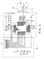
Fig. 3 is a circuit diagram of the present invention (1), and -
Fig. 4 is a circuit diagram of the present invention (2). - Referring to
Figs. 1 and2 , a preferred embodiment of a flashlight of the present invention includes amain part 1, aswitch 11, alight source 12, anLCD display 2, and acontrol device 3. - The
switch 11 is fitted on themain part 1. Thelight source 12 is fitted to a front end of themain part 1, andbatteries 13 are held in themain part 1. TheLCD display 2 is fitted on themain part 1 while thecontrol device 3 is disposed in themain part 1. - Referring to
Figs. 1 to 4 , thecontrol device 3 includes afunction switching unit 31, a lightsource controlling unit 32, an electricity content checking and measuringunit 33, and anLCD displaying unit 34. Thefunction switching unit 31 is connected to theswitch 11 fitted on themain part 1. The lightsource controlling unit 32 is connected to thelight source 12 on the front end of themain part 1. The electricity content checking and measuringunit 33 is connected to thebatteries 13 held in themain part 1. And, theLCD displaying unit 34 is connected to theLCD display 2. - Therefore, in use, the
control device 3 will measure the amount of electricity left in thebatteries 13 through the electricity content checking and measuringunit 33; in the measurement, the electricity amount checking and measuringunit 33 will acquire data on the electricity content of thebatteries 13, which data will be first transformed into an analogue signal. Next, the analogue signal will be transformed into a digital signal by means of ADC (analogue-to-digital conversion) function of thecontrol device 3, and a calculation will be carried out based on the digital signal with the result of the calculation, i.e. information on the electricity content of thebatteries 13, being shown in the form of bars on theLCD display 2 through theLCD displaying unit 34. At the same time, thecontrol device 3 will carry out calculation based on the electricity content of thebatteries 13 so as to find out the length of time thebatteries 13 will last, and the result of the calculation will also be shown on theLCD display 2 through theLCD displaying unit 34. - When the
switch 11 is moved to a certain position, thefunction switching unit 31 of thecontrol device 3 will detect change of theswitch 11, and thecontrol device 3 will send out a PWM (pulse-width modulation) pulse signal to the lightsource controlling unit 32 such that the lightsource controlling unit 32 makes thelight source 12 shine in a certain manner according to a new position of theswitch 11; thelight source 12 can keep on shining or flash on and off repeatedly at various frequencies and with various brightnesses; in other words, the flashing frequency and brightness of thelight source 12 can be changed with the help of theswitch 11 and thecontrol device 3. Furthermore, information about the way thelight source 12 is producing light will also be shown on theLCD display 2 through theLCD displaying unit 34 at the same time. In addition, in emergency, the user is allowed to move theswitch 11 such that the lightsource controlling unit 32 makes thelight source 12 emit very bright light to serve as warning signals. - From the above description, it can be seen that the present invention is convenient to use, and has the following advantages: the flashlight of the present invention has the LCD display for showing information on the electricity content of the batteries as well as the length of time the batteries will last; with the help of both the switch and the control device, the flashlight can be switched so as to shine in either one of various ways, e.g. flashing on and off repeatedly at a certain frequency, and keeping on shining, and it can be switched so as to produce light of either one of various brightnesses; furthermore, the flashlight can be to switched so as to produce very bright light, which can serve as warning signals in emergency.
Claims (8)
- Structure of a flashlight with LCD display, comprisinga main part,a switch fitted on the main part,a light source fitted to a front end of the main part,a plurality of batteries held in the main part,an LCD display fitted on the main part, anda control device positioned in the main part, the control device including:(a) an electricity content checking and measuring unit connected to the batteries for measuring amount of electricity left in the batteries; in measurement, the electricity content checking and measuring unit being going to acquire data on electricity content of the batteries, which data will be transformed into an analogue signal; the analogue signal being going to be transformed into a digital signal by means of ADC (analogue-to-digital conversion) function of the control device; and(b) an LCD displaying unit connected to the LCD display; a calculation being going to be carried out based on said digital signal with result of said calculation being shown on the LCD display through the LCD displaying unit.
- The flashlight structure as recited in claim 1, wherein the electricity content of the batteries is shown on the LCD display in a form of plural bars.
- The flashlight structure as recited in claim 1, wherein the control device will carry out calculation based on the electricity content of the batteries so as to find out length of time the batteries will last; a result of said calculation being going to be shown on the LCD display.
- The flashlight structure as recited in claim 1, wherein the control device further includes:a function switching unit connected to the switch fitted on the main part, anda light source controlling unit connected to the light source fitted on the front end of the main part; when the switch is displaced, the function switching unit will detect change of the switch, and the control device will send out a PWM (pulse-width modulation) pulse signal to the light source controlling unit such that the light source controlling unit makes the light source shine in a way according to position of the switch.
- The flashlight structure as recited in claim 4, wherein brightness of the light source on the front end of the main part can be changed.
- The flashlight structure as recited in claim 4, wherein the light source on the front end of the main part can flash on and off repeatedly, and flashing frequency of the light source can be changed.
- The flashlight structure as recited in claim 4, wherein the light source on the front end of the main part can emit highly bright light.
- The flashlight structure as recited in claim 4, wherein information about a way the light source is producing light will be shown on the LCD display through the LCD displaying unit at same time.
Applications Claiming Priority (1)
| Application Number | Priority Date | Filing Date | Title |
|---|---|---|---|
| CNU2006201543627U CN200993313Y (en) | 2006-12-05 | 2006-12-05 | flashlight |
Publications (1)
| Publication Number | Publication Date |
|---|---|
| EP1930649A1 true EP1930649A1 (en) | 2008-06-11 |
Family
ID=38946387
Family Applications (1)
| Application Number | Title | Priority Date | Filing Date |
|---|---|---|---|
| EP07020907A Withdrawn EP1930649A1 (en) | 2006-12-05 | 2007-10-25 | Flashlight with LCD display |
Country Status (6)
| Country | Link |
|---|---|
| EP (1) | EP1930649A1 (en) |
| JP (1) | JP3139162U (en) |
| CN (1) | CN200993313Y (en) |
| AU (1) | AU2007101125A4 (en) |
| CA (1) | CA2612647A1 (en) |
| HK (1) | HK1109011A2 (en) |
Cited By (6)
| Publication number | Priority date | Publication date | Assignee | Title |
|---|---|---|---|---|
| GB2505253A (en) * | 2012-08-24 | 2014-02-26 | Ultimate Sports Engineering | Lamp |
| US10704250B2 (en) | 2016-10-28 | 2020-07-07 | Milwaukee Electric Tool Corporation | Sewer cleaning machine |
| USD906559S1 (en) | 2018-04-26 | 2020-12-29 | Milwaukee Electric Tool Corporation | Light |
| US11098858B2 (en) | 2018-04-26 | 2021-08-24 | Milwaukee Electric Tool Corporation | Portable light having a pivotable light head |
| US11505229B2 (en) | 2018-04-13 | 2022-11-22 | Milwaukee Electric Tool Corporation | Tool support |
| US12409478B2 (en) | 2019-06-10 | 2025-09-09 | Milwaukee Electric Tool Corporation | Transportable machine including a track system |
Families Citing this family (5)
| Publication number | Priority date | Publication date | Assignee | Title |
|---|---|---|---|---|
| DE102008043212A1 (en) * | 2008-10-28 | 2010-04-29 | Robert Bosch Gmbh | Energy expenditure device and method for issuing a remaining possibility of use |
| CN101896025B (en) * | 2010-06-21 | 2014-03-12 | 海洋王照明科技股份有限公司 | System and method for controlling lamp |
| CN104111427A (en) * | 2013-10-23 | 2014-10-22 | 吴长江 | Electric torch battery electric quantity inquiring device and electric torch |
| CN112732141A (en) * | 2021-01-13 | 2021-04-30 | 展讯通信(天津)有限公司 | Flashlight control method and device, electronic equipment and storage medium |
| CN115717687A (en) * | 2022-11-18 | 2023-02-28 | 深圳市中孚能电气设备有限公司 | Multifunctional flashlight and its control method |
Citations (7)
| Publication number | Priority date | Publication date | Assignee | Title |
|---|---|---|---|---|
| US4962347A (en) * | 1988-02-25 | 1990-10-09 | Strategic Energy, Ltd. | Flashlight with battery tester |
| US6184794B1 (en) * | 1993-11-01 | 2001-02-06 | Eveready Battery Company, Inc. | Portable lighting device having externally attached voltage tester |
| DE10161017A1 (en) * | 2001-12-07 | 2003-06-12 | Rolf Wilhelm Haupt | Battery-powered lamp has control electronics that form light source control signal taking into account a measurement signal derived from battery voltage using stored relationship |
| GB2384373A (en) * | 2002-01-19 | 2003-07-23 | Robert James Hancox | Torch or cycle lamp with display means |
| US20050002186A1 (en) * | 2003-07-01 | 2005-01-06 | Vector Products, Inc. | Multi-beam flashlight |
| US20060187658A1 (en) * | 2005-01-21 | 2006-08-24 | Cyberlux Corporation | Portable light device |
| US20060239003A1 (en) * | 2005-04-20 | 2006-10-26 | Eisenson Henry L | Battery operated device with a battery life indicator |
-
2006
- 2006-12-05 CN CNU2006201543627U patent/CN200993313Y/en not_active Expired - Lifetime
-
2007
- 2007-10-25 EP EP07020907A patent/EP1930649A1/en not_active Withdrawn
- 2007-11-20 JP JP2007008964U patent/JP3139162U/en not_active Expired - Fee Related
- 2007-11-21 HK HK07112715A patent/HK1109011A2/en not_active IP Right Cessation
- 2007-11-23 CA CA002612647A patent/CA2612647A1/en not_active Abandoned
- 2007-11-26 AU AU2007101125A patent/AU2007101125A4/en not_active Expired
Patent Citations (7)
| Publication number | Priority date | Publication date | Assignee | Title |
|---|---|---|---|---|
| US4962347A (en) * | 1988-02-25 | 1990-10-09 | Strategic Energy, Ltd. | Flashlight with battery tester |
| US6184794B1 (en) * | 1993-11-01 | 2001-02-06 | Eveready Battery Company, Inc. | Portable lighting device having externally attached voltage tester |
| DE10161017A1 (en) * | 2001-12-07 | 2003-06-12 | Rolf Wilhelm Haupt | Battery-powered lamp has control electronics that form light source control signal taking into account a measurement signal derived from battery voltage using stored relationship |
| GB2384373A (en) * | 2002-01-19 | 2003-07-23 | Robert James Hancox | Torch or cycle lamp with display means |
| US20050002186A1 (en) * | 2003-07-01 | 2005-01-06 | Vector Products, Inc. | Multi-beam flashlight |
| US20060187658A1 (en) * | 2005-01-21 | 2006-08-24 | Cyberlux Corporation | Portable light device |
| US20060239003A1 (en) * | 2005-04-20 | 2006-10-26 | Eisenson Henry L | Battery operated device with a battery life indicator |
Cited By (10)
| Publication number | Priority date | Publication date | Assignee | Title |
|---|---|---|---|---|
| GB2505253A (en) * | 2012-08-24 | 2014-02-26 | Ultimate Sports Engineering | Lamp |
| GB2505253B (en) * | 2012-08-24 | 2015-09-02 | Ultimate Sports Engineering | A light |
| US10704250B2 (en) | 2016-10-28 | 2020-07-07 | Milwaukee Electric Tool Corporation | Sewer cleaning machine |
| US11603653B2 (en) | 2016-10-28 | 2023-03-14 | Milwaukee Electric Tool Corporation | Sewer cleaning machine |
| US11970850B2 (en) | 2016-10-28 | 2024-04-30 | Milwaukee Electric Tool Corporation | Sewer cleaning machine |
| US12252877B2 (en) | 2016-10-28 | 2025-03-18 | Milwaukee Electric Tool Corporation | Sewer cleaning machine |
| US11505229B2 (en) | 2018-04-13 | 2022-11-22 | Milwaukee Electric Tool Corporation | Tool support |
| USD906559S1 (en) | 2018-04-26 | 2020-12-29 | Milwaukee Electric Tool Corporation | Light |
| US11098858B2 (en) | 2018-04-26 | 2021-08-24 | Milwaukee Electric Tool Corporation | Portable light having a pivotable light head |
| US12409478B2 (en) | 2019-06-10 | 2025-09-09 | Milwaukee Electric Tool Corporation | Transportable machine including a track system |
Also Published As
| Publication number | Publication date |
|---|---|
| CN200993313Y (en) | 2007-12-19 |
| JP3139162U (en) | 2008-01-31 |
| AU2007101125A4 (en) | 2008-01-24 |
| HK1109011A2 (en) | 2008-05-23 |
| CA2612647A1 (en) | 2008-06-05 |
Similar Documents
| Publication | Publication Date | Title |
|---|---|---|
| EP1930649A1 (en) | Flashlight with LCD display | |
| US9220155B2 (en) | Lamp and switch apparatus thereof | |
| EP1602873B1 (en) | Portable signal light, motor vehicle guiding tool, and motor vehicle guiding method | |
| CA2482966A1 (en) | Apparatus for lighting a patient monitor front panel | |
| US6674832B2 (en) | Pedometer with an illumination lamp | |
| KR970076933A (en) | Knob lighting device of the switch | |
| US7134214B1 (en) | Illuminated ruler | |
| JP2001210478A (en) | Light with heat ray sensor | |
| US20080123327A1 (en) | Structure of a flashlight with LCD display | |
| CN103149401A (en) | Multifunctional simple oscilloscope | |
| JP2005243256A (en) | Lighting system | |
| CN202825667U (en) | Lighting screwdriver | |
| US20250369603A1 (en) | Rotary Folding Lamp | |
| CN209977882U (en) | Multifunctional LED warning lamp for traffic police | |
| CN219912971U (en) | Lamp cap and lamp | |
| CN209893156U (en) | Wireless remote control LED flashing rod | |
| CN201025332Y (en) | Lighting device for spanner tool | |
| JP5056641B2 (en) | Power supply | |
| JP3061915U (en) | Voltage detector | |
| JP2920944B2 (en) | Lighting equipment | |
| KR20220038556A (en) | Attachment vehicle interior lamp | |
| US20070153513A1 (en) | Signal lantern | |
| JP2012089282A (en) | Lighting apparatus | |
| JP2004235143A (en) | Signal lamp to display in multiple forms | |
| KR200231677Y1 (en) | Indoor Lighting Automatic ON/OFF Controller with Digital illuminance Indicator |
Legal Events
| Date | Code | Title | Description |
|---|---|---|---|
| PUAI | Public reference made under article 153(3) epc to a published international application that has entered the european phase |
Free format text: ORIGINAL CODE: 0009012 |
|
| AK | Designated contracting states |
Kind code of ref document: A1 Designated state(s): AT BE BG CH CY CZ DE DK EE ES FI FR GB GR HU IE IS IT LI LT LU LV MC MT NL PL PT RO SE SI SK TR |
|
| AX | Request for extension of the european patent |
Extension state: AL BA HR MK RS |
|
| AKX | Designation fees paid | ||
| REG | Reference to a national code |
Ref country code: DE Ref legal event code: 8566 |
|
| STAA | Information on the status of an ep patent application or granted ep patent |
Free format text: STATUS: THE APPLICATION IS DEEMED TO BE WITHDRAWN |
|
| 18D | Application deemed to be withdrawn |
Effective date: 20081212 |