EP1930641A1 - Pipe joint, refrigeration device, heat pump hot water supply device, closing valve, water supply piping, method of connecting piping, and in-the-field piping method - Google Patents
Pipe joint, refrigeration device, heat pump hot water supply device, closing valve, water supply piping, method of connecting piping, and in-the-field piping method Download PDFInfo
- Publication number
- EP1930641A1 EP1930641A1 EP06798448A EP06798448A EP1930641A1 EP 1930641 A1 EP1930641 A1 EP 1930641A1 EP 06798448 A EP06798448 A EP 06798448A EP 06798448 A EP06798448 A EP 06798448A EP 1930641 A1 EP1930641 A1 EP 1930641A1
- Authority
- EP
- European Patent Office
- Prior art keywords
- pipe
- joint
- sleeve
- joint body
- fastening member
- Prior art date
- Legal status (The legal status is an assumption and is not a legal conclusion. Google has not performed a legal analysis and makes no representation as to the accuracy of the status listed.)
- Withdrawn
Links
Images


Classifications
-
- F—MECHANICAL ENGINEERING; LIGHTING; HEATING; WEAPONS; BLASTING
- F25—REFRIGERATION OR COOLING; COMBINED HEATING AND REFRIGERATION SYSTEMS; HEAT PUMP SYSTEMS; MANUFACTURE OR STORAGE OF ICE; LIQUEFACTION SOLIDIFICATION OF GASES
- F25B—REFRIGERATION MACHINES, PLANTS OR SYSTEMS; COMBINED HEATING AND REFRIGERATION SYSTEMS; HEAT PUMP SYSTEMS
- F25B41/00—Fluid-circulation arrangements
-
- F—MECHANICAL ENGINEERING; LIGHTING; HEATING; WEAPONS; BLASTING
- F16—ENGINEERING ELEMENTS AND UNITS; GENERAL MEASURES FOR PRODUCING AND MAINTAINING EFFECTIVE FUNCTIONING OF MACHINES OR INSTALLATIONS; THERMAL INSULATION IN GENERAL
- F16L—PIPES; JOINTS OR FITTINGS FOR PIPES; SUPPORTS FOR PIPES, CABLES OR PROTECTIVE TUBING; MEANS FOR THERMAL INSULATION IN GENERAL
- F16L19/00—Joints in which sealing surfaces are pressed together by means of a member, e.g. a swivel nut, screwed on, or into, one of the joint parts
- F16L19/08—Joints in which sealing surfaces are pressed together by means of a member, e.g. a swivel nut, screwed on, or into, one of the joint parts with metal rings which bite into the wall of the pipe
- F16L19/10—Joints in which sealing surfaces are pressed together by means of a member, e.g. a swivel nut, screwed on, or into, one of the joint parts with metal rings which bite into the wall of the pipe the profile of the ring being altered
- F16L19/14—Joints in which sealing surfaces are pressed together by means of a member, e.g. a swivel nut, screwed on, or into, one of the joint parts with metal rings which bite into the wall of the pipe the profile of the ring being altered the rings being integral with one of the connecting parts
-
- F—MECHANICAL ENGINEERING; LIGHTING; HEATING; WEAPONS; BLASTING
- F16—ENGINEERING ELEMENTS AND UNITS; GENERAL MEASURES FOR PRODUCING AND MAINTAINING EFFECTIVE FUNCTIONING OF MACHINES OR INSTALLATIONS; THERMAL INSULATION IN GENERAL
- F16L—PIPES; JOINTS OR FITTINGS FOR PIPES; SUPPORTS FOR PIPES, CABLES OR PROTECTIVE TUBING; MEANS FOR THERMAL INSULATION IN GENERAL
- F16L19/00—Joints in which sealing surfaces are pressed together by means of a member, e.g. a swivel nut, screwed on, or into, one of the joint parts
- F16L19/08—Joints in which sealing surfaces are pressed together by means of a member, e.g. a swivel nut, screwed on, or into, one of the joint parts with metal rings which bite into the wall of the pipe
-
- F—MECHANICAL ENGINEERING; LIGHTING; HEATING; WEAPONS; BLASTING
- F16—ENGINEERING ELEMENTS AND UNITS; GENERAL MEASURES FOR PRODUCING AND MAINTAINING EFFECTIVE FUNCTIONING OF MACHINES OR INSTALLATIONS; THERMAL INSULATION IN GENERAL
- F16L—PIPES; JOINTS OR FITTINGS FOR PIPES; SUPPORTS FOR PIPES, CABLES OR PROTECTIVE TUBING; MEANS FOR THERMAL INSULATION IN GENERAL
- F16L19/00—Joints in which sealing surfaces are pressed together by means of a member, e.g. a swivel nut, screwed on, or into, one of the joint parts
- F16L19/08—Joints in which sealing surfaces are pressed together by means of a member, e.g. a swivel nut, screwed on, or into, one of the joint parts with metal rings which bite into the wall of the pipe
- F16L19/10—Joints in which sealing surfaces are pressed together by means of a member, e.g. a swivel nut, screwed on, or into, one of the joint parts with metal rings which bite into the wall of the pipe the profile of the ring being altered
-
- F—MECHANICAL ENGINEERING; LIGHTING; HEATING; WEAPONS; BLASTING
- F24—HEATING; RANGES; VENTILATING
- F24D—DOMESTIC- OR SPACE-HEATING SYSTEMS, e.g. CENTRAL HEATING SYSTEMS; DOMESTIC HOT-WATER SUPPLY SYSTEMS; ELEMENTS OR COMPONENTS THEREFOR
- F24D17/00—Domestic hot-water supply systems
- F24D17/02—Domestic hot-water supply systems using heat pumps
-
- F—MECHANICAL ENGINEERING; LIGHTING; HEATING; WEAPONS; BLASTING
- F24—HEATING; RANGES; VENTILATING
- F24H—FLUID HEATERS, e.g. WATER OR AIR HEATERS, HAVING HEAT-GENERATING MEANS, e.g. HEAT PUMPS, IN GENERAL
- F24H1/00—Water heaters, e.g. boilers, continuous-flow heaters or water-storage heaters
- F24H1/54—Water heaters for bathtubs or pools; Water heaters for reheating the water in bathtubs or pools
-
- Y—GENERAL TAGGING OF NEW TECHNOLOGICAL DEVELOPMENTS; GENERAL TAGGING OF CROSS-SECTIONAL TECHNOLOGIES SPANNING OVER SEVERAL SECTIONS OF THE IPC; TECHNICAL SUBJECTS COVERED BY FORMER USPC CROSS-REFERENCE ART COLLECTIONS [XRACs] AND DIGESTS
- Y10—TECHNICAL SUBJECTS COVERED BY FORMER USPC
- Y10T—TECHNICAL SUBJECTS COVERED BY FORMER US CLASSIFICATION
- Y10T29/00—Metal working
- Y10T29/49—Method of mechanical manufacture
- Y10T29/49826—Assembling or joining
- Y10T29/49908—Joining by deforming
- Y10T29/49925—Inward deformation of aperture or hollow body wall
- Y10T29/49934—Inward deformation of aperture or hollow body wall by axially applying force
Definitions
- the present invention relates to a pipe joint for joining, for example, a refrigerant pipe, a refrigeration device using the pipe joint, a heat pump hot water supply device using the pipe joint, a closing valve using the pipe joint, a water supply piping, a method for connecting piping, and an in-the-field piping method.
- a pipe joint with which a pipe is inserted into a joint hole of a joint body and then a nut is screwed into the joint body to connect the pipe to the joint hole of the joint body has been known as a pipe joint used for joining of a pipe through which fluid is made to flow into a refrigerant pipe of a refrigeration device, for example.
- a flareless joint as disclosed by a prior art of Patent Document 1 has been frequently adopted as the pipe joint as described above.
- Fig. 16 shows the flareless joint disclosed in the prior art of Patent Document 1.
- This flareless joint is constructed by a joint body 101, a nut 102, and a sleeve 103 provided between the joint body 101 and the nut 102.
- the sleeve 103 is mounted on the outer peripheral surface 104a of the pipe 104.
- the distal portion 104b of the pipe 104 is inserted into a joint hole 101a of the joint body 101, and the threaded portion 102a of the nut 102 is engaged with the threaded portion 101b of the joint body 101.
- the proximal end face 103a of the sleeve 103 receives pressing force from a pressing face 102b of the nut 102, and the distal portion 103b of the sleeve 103 receives pressing force from a taper face 101c of the joint body 101. Therefore, the distal portion 103b of the sleeve 103 bites into the outer peripheral surface 104a, and the pipe 104 of the pipe 104 is connected to the joint hole 101a of the joint body 101.
- the flareless joint ensures the sealing performance of the joint portion between the pipe 104 and the joint body 101 by the biting of the sleeve 103 into the pipe 104.
- Patent Document 1 Japanese Laid-Open Patent Publication No. 2003-74768
- the pipe joint as described above is constructed by the joint body, the nut, and the sleeve, and thus there is a risk that a sleeve, which is a relatively small part, may be lost until a pipe is joined. Furthermore, when a pipe is joined, a sleeve, which is a small part, is assembled to the pipe. This can lower the workability. Furthermore, with respect to the sleeve, the site receiving pressing force and the site biting into the pipe are exposed, and thus when the sleeve is stored as a spare or the sleeve is handled, these sites are liable to scratching. This scratching may adversely affect the sealing performance of the joint portion of the pipe joint.
- An objective of the present invention is to provide a pipe joint that prevents loss of a sleeve and ensures the sealing performance of a joint portion while enhancing the workability at the pipe joining operation, a refrigeration device using the pipe joint, etc., a method for connecting piping, etc.
- a pipe joint having a joint body forming a joint hole to join a pipe, a fastening member fastened to the joint body, and a sleeve biting into the outer periphery of the pipe by fastening of the fastening member to the joint body under the state that the pipe is inserted into the joint hole.
- the sleeve is integrated with the joint body or the fastening member before the fastening member is fastened to the joint body, and it is cut off and separated from the joint body or the fastening member by the fastening of the fastening member to the joint body.
- the sleeve which bites into the outer periphery of the pipe by the fastening of the fastening member to the joint body is integrated with the joint body or the fastening member before the fastening member is fastened to the joint body. Therefore, the sleeve is prevented from being lost until the pipe is joined as compared with a case where the sleeve is constructed as a separate body from the joint body or the fastening member like the prior art, and thus it is unnecessary to stock a sleeve as a spare. Furthermore, it is unnecessary to assemble the sleeve when the pipe is joined, so that the workability at the pipe connecting operation is enhanced.
- the sleeve is integrated with the joint body or the fastening member, and thus the biting site, etc., of the sleeve is prevented from being exposed from the joint body or the fastening member to the outside. Therefore, when the pipe joint is handled, for example, the biting site of the sleeve into the pipe is prevented from being scratched. Therefore, the sealing performance of the joint portion of the pipe joint is prevented from being degraded by the scratching of the sleeve.
- the sleeve Since the sleeve is cut off and separated from the joint body or the fastening member by the fastening of the joint member to the joint body, the separated sleeve bites into the outer periphery of the pipe and the pipe is connected to the joint hole of the joint body while ensuring the sealing performance of the joint portion as in the case of the conventional construction.
- a refrigeration device in which the pipe joint described above is used for the connection portion of a refrigerant pipe. According to this construction, a refrigeration device is provided in which the loss of a sleeve is prevented, and the sealing performance of the joint portion is ensured while enhancing the workability at the pipe joining operation.
- a heat pump hot water supply device in which the pipe joint described above is used for the connection portion of a refrigerant pipe. According to this construction, a heat pump hot water supply device is provided in which the loss of a sleeve is prevented, and the sealing performance of the joint portion is ensured while enhancing the workability at the pipe joining operation.
- a closing valve in which the pipe joint described above is used for the connection portion of a pipe. According to this construction, a closing valve is provided in which the loss of a sleeve is prevented, and the sealing performance of the joint portion is ensured while enhancing the workability at the pipe joining operation.
- a water supply piping in which the pipe joint described above is used for the connection of a pipe.
- a water supply piping is provided in which the loss of a sleeve is prevented, and the sealing performance of the joint portion is ensured while enhancing the workability at the pipe joining operation.
- a piping connecting method for a pipe joint having a joint body having a joint hole formed to join a pipe, a fastening member fastened to the joint body, and a sleeve biting into the outer periphery of the pipe by the fastening of the fastening member to the joint body under the state that the pipe is inserted into the joint hole.
- the sleeve is integrated with the fastening body or the fastening member.
- the connecting method includes a step of inserting the pipe into the joint hole of the joint body, a step of cutting off and separating the sleeve from the joint body or the fastening member by a fastening operation of the fastening member to the joint body, and a step of making the sleeve bite into the outer periphery of the pipe by the fastening operation of the fastening member to the joint body.
- the pipe when the pipe is connected to the pipe joint, the pipe is inserted into the joint hole of the joint body. Subsequently, the sleeve which is integrated with the joint body or the fastening member is cut off from the joint body or the fastening member by the fastening operation of the fastening member to the joint body. Then, the separated sleeve bites into the outer periphery of the pipe by the fastening operation of the fastening member to the joint body, whereby the pipe is connected. As described above, the sleeve is integrated with the joint body or the fastening member, the sleeve is prevented from being lost until the pipe is connected, and the workability at the pipe joining operation is enhanced. Furthermore, the sleeve separated by the fastening operation of the fastening member bites into the outer periphery of the pipe by the fastening operation, and thus a method for connecting piping which ensure the sealing performance of the joint portion is provided.
- an in-the-field piping method in which a piping work is carried out at a pipe job site by using the piping connecting method.
- the piping work is carried out by the fastening operation of the fastening member to the joint body, etc., so that the piping work is safely and easily performed without using any facilities for brazing, etc.
- a first embodiment of a pipe joint according to the present invention will be described with reference to Figs. 1 to 5 .
- Fig. 1 is a partial cross-sectional view showing the construction of a pipe joint.
- the pipe joint 1 connects pipes 11 and 12, and has a joint body 13 having a cylindrical shape into which the pipes 11, 12 are inserted, a nut 14 as a fastening member threaded with the joint body 13, and a sleeve 15 which is interposed between the joint body 13 and the nut 14 at the pipe joining operation and has an annular shape.
- the pipe 11 is fixed to the joint body 13, for example, by brazing at a socket portion 13a formed at the distal portion of the joint body 13.
- the distal portion 12a of the pipe 12 to be connected to the joint body 13 is inserted into a joint hole 13b formed at the proximal portion of the joint body 13.
- the distal portion 15a of the sleeve 15 bites into the outer peripheral surface 12b of the pipe 12 by the thread engagement between the nut 14 and the joint body 13, whereby the pipe 12 inserted into the joint body 13 is joined to the joint body 13.
- the sleeve 15 biting into the pipe 12 is integrated with the nut 14 before the pipe 12 is connected, and is cut off and separated from the nut 14 by the thread engagement between the nut 14 and the joint body 13.
- Fig. 2 is a partial cross-sectional view showing the joint body 13.
- the joint body 13 has the socket portion 13a to which the pipe 11 is fixed, the joint hole 13b in which the pipe 12 is inserted, an external thread portion 13c with which the nut 14 is threaded, a guide face 13d, and a nut portion 13e formed on the outer peripheral surface of the joint body 13.
- the guide face 13d guides the outer peripheral surface 15c of the sleeve 15 when the sleeve 15 bites into the pipe 12.
- the socket portion 13a has a circular-hole shape, and has an inner diameter which is substantially equal to the outer diameter of the pipe 11 to be fixed.
- the joint hole 13b has a circular-hole shape, and has an inner diameter D0 which is substantially equal to the outer diameter Dp of the pipe 12 to be inserted.
- the socket portion 13a and the joint hole 13b communicate with each other through an inner space 13f.
- the external thread portion 13c has a threaded shape at the place corresponding to the joint hole 13b and the inner space 13f on the outer peripheral surface of the joint body 13 so that the external thread portion 13c is threaded with the nut 14.
- the guide face 13d is located at the proximal portion of the joint body 13, that is, the inlet of the pipe 12 in the joint hole 13b, and it expands in diameter from the inner side to the outer side.
- the outer peripheral surface 15c of the sleeve 15 is guided by the guide face 13d, and the sleeve 15 bites into the outer peripheral surface 12b of the pipe 12.
- the joint body 13 is held by the nut portion 13e when the nut 14 is threaded with the joint body 13.
- Fig. 3 is a partial cross-sectional view showing the nut 14.
- the nut 14 has an internal thread portion 14a to be threaded with the external thread portion 13c of the joint body 13, and a holding hole 14b for holding the outer periphery of the pipe 12.
- the sleeve 15 is integrated with the nut 14.
- the internal thread portion 14a is formed on the inner peripheral surface of the distal portion of the nut 14 which is threaded with the joint body 13.
- the holding hole 14b is formed at the proximal portion of the nut 14, and has a circular-hole shape. Furthermore, the holding hole 14b has an inner diameter which is substantially equal to the outer diameter Dp of the pipe 12 to be held.
- the sleeve 15 of this embodiment is integrally formed with the nut 14, and formed on the inner peripheral surface of the proximal portion of the nut 14. As shown in Fig. 3 , the distal end of the sleeve 15 is located in the nut 14, and the sleeve 15 is prevented from being exposed to the outside from the nut 14. Accordingly, the sleeve 15 is prevented from being scratched when the nut 14 is handled.
- the sleeve 15 has an inner peripheral surface 15b facing the pipe 12, an outer peripheral surface 15c as a guided face to be guided by the guide face 13d of the joint body 13 when the sleeve 15 bites into the pipe 12, and a proximal end face 15d receiving pressing force when the sleeve 15 bites into the pipe 12.
- the inner peripheral surface 15b has an inner diameter which is substantially equal to the outer diameter Dp of the pipe 12.
- the outer peripheral surface 15c expands in diameter from the distal end to the proximal end of the sleeve 15.
- An inclination angle ⁇ of the outer peripheral surface 15c relative to a line extending in the fastening direction of the nut 14 is set to be smaller than the inclination angle ⁇ of the guide face 13d relative to the same line. Accordingly, when the nut 14 is threaded with the joint body 13, the distal portion 15a of the sleeve 15 is deformed inward and bites into the outer peripheral surface 12b of the pipe 12.
- the inclination angle ⁇ of the outer peripheral surface 15c is set to be larger than the half angle of the inclination angle ⁇ of the guide face 13d. Accordingly, the inclination angle ⁇ is prevented from being excessively small, and the pressing force from the guide face 13d is efficiently applied to the sleeve 15.
- the inclination angle ⁇ of the guide face 13d of the joint body 13 is preferably set in the range from 15° to 30° to smoothly guide the distal portion 15a of the sleeve 15, and more preferably set in the range from 20° to 25°.
- the distal end 15g of the sleeve 15 biting into the pipe 12 has a sharp-edge shape. Accordingly, the sleeve 15 reliably bites into the pipe 12, and the sealing performance at the biting site at which the sleeve 15 bites into the pipe 12 is enhanced.
- the proximal end face 15d faces a contact portion 14c formed to be nearer to the distal end of the nut 14 than the holding hole 14b on the inner peripheral surface of the nut 14.
- the proximal end face 15d receives the pressing force from the contact portion 14c after the sleeve 15 is separated from the nut 14, whereby the distal portion 15a bites into the outer peripheral surface 12b of the pipe 12.
- the sleeve 15 is integrated with the nut 14 at the base portion 15e thereof.
- the base portion 15e of the sleeve 15 is formed to be thinner. Therefore, the base portion 15e is cut off, and the sleeve 15 is easily separated from the nut 14.
- the sleeve 15 is formed of a material the hardness of which is equal to or greater than a material of which the pipe 12 is formed.
- the sleeve 15 is formed of brass or stainless steel, and when the pipe 12 is formed of stainless steel, the sleeve 15 is formed of stainless steel. Accordingly, the sleeve 15 easily bites into the pipe 12, and the sealing performance at the site at which the sleeve 15 bites into the pipe 12 is enhanced.
- FIGs. 4(a) to 4(c) are cross-sectional views showing the operation of the surrounding of the sleeve 15 of the pipe joint 1.
- the guide face 13d of the joint body 13 abuts against a part of the outer peripheral surface 15c of the sleeve 15, and the pressing force to the outer peripheral surface 15c by the guide face 13d is increased in accordance with the thread engagement of the nut 14. Accordingly, at the base portion 15e of the sleeve 15, shearing force applied along the screwing direction of the nut 14 is increased, and the base portion 15e of the sleeve 15 is cut off. At this time, the cut surface 14d of the nut 14 and the cut surface 15f of the sleeve 15 are formed along the thickness direction of the base portion 15e of the sleeve 15, that is, the screwing direction of the nut 14.
- the cut surfaces 14d, 15f are formed along substantially the same direction as the acting direction of the shearing force, and thus the base portion 15e is easily cut off by the screwing of the nut 14.
- the nut 14 and the sleeve 15 are separated from each other as shown in Fig. 4(b) .
- the guide face 13d of the joint body 13 abuts against a part of the outer peripheral surface 15c of the sleeve 15, and the contact portion 14c of the nut 14 abuts against the proximal end face 15d of the sleeve 15. Then, in accordance with the screwing of the nut 14, the proximal end face 15d of the sleeve 15 receives pressing force from the contact portion 14c of the nut 14, and the outer peripheral surface 15c of the sleeve 15 is guided by the guide face 13d of the joint body 13, whereby the distal portion 15a of the sleeve 15 bites into the outer peripheral surface 12b of the pipe 12 as shown in Fig. 4(c) .
- the cut surface 14d of the nut 14 is distant from the joint body 13 by a back clearance portion 13g formed on the outer peripheral surface of the proximal portion of the joint body 13 from the time when the nut 14 and the sleeve 15 are separated from each other until the time when the sleeve 15 bites into the pipe 12.
- the cut surface 15f of the sleeve 15 is distant from the nut 14 by a recess portion 14e formed to be nearer to the distal end of the nut 14 than the contact portion 14c on the inner peripheral surface of the nut 14. Accordingly, the cut surfaces 14d, 15f are prevented from being brought into contact with the joint body 13 or the nut 14.
- the nut 14 is sufficiently screwed into the joint body 13, so that the sleeve 15 sufficiently bites into the pipe 12.
- the pipe joint 1 joins the pipe 12 to the joint body 13 by making the distal portion 15a of the sleeve 15 bite into the outer peripheral surface 12b of the pipe 12.
- the boundary between the distal portion 15a of the sleeve 15 and the outer peripheral surface 12b of the pipe 12 is hermetically sealed by the biting of the distal portion 15a of the sleeve 15.
- the outer peripheral surface 15c of the sleeve 15 and the guide face 13d of the joint body 13 are brought into close contact with each other, whereby the boundary between the outer peripheral surface 15c of he sleeve 15 and the guide face 13d of the joint body 13 is hermetically sealed. The sealing performance between the pipe 12 and the joint body 13 is ensured by the hermetical sealing at these places.
- the variation of the sealing performance of the pipe joint 1 in the connecting operation of the pipe 12 and the variation of the fastening torque applied to the joint body 13 of the nut 14 with respect to the variation of the shape of the pipe joint 1 and the pipe 12 were measured, and the relationship as shown in Fig. 5 was obtained.
- the abscissa axis of Fig. 5 shows the biting coefficient ⁇ Dp - (D0 - 2t) ⁇ /Dp, which is set by using the outer diameter Dp of the pipe 12, the inner diameter D0 of the joint hole 13b of the joint body 13, and the thickness t in the radial direction of the distal portion 15a of the sleeve 15 (see Fig. 3 ).
- (D0 - 2t) shows the inner diameter obtained by subtracting the thickness 2t of the biting site of the sleeve 15 into the pipe 12 from the inner diameter D0 of the joint hole 13b of the joint body 13. It can be assumed that the pipe 12 having the outer diameter Dp is inserted into the site having this inner diameter in the joining operation of the pipe 12. Therefore, ⁇ Dp - (D0 - 2t) ⁇ represents the biting amount of the distal portion 15a of the sleeve 15 into the pipe 12.
- the biting coefficient ⁇ Dp - (D0 - 2t) ⁇ /Dp may be used as a parameter representing the biting ratio of the sleeve 15 to the pipe 12.
- X in Fig. 5 represents the variation of the sealing performance of the pipe joint 1 with respect to the variation of the biting coefficient.
- the ordinate axis represents the leak amount Q (cc/sec) from the joint portion of the pipe 12.
- the leak amount Q from the joint portion is obtained by filling the pipe 12 and the pipe joint 1 with helium and measuring the leak amount of helium by a helium leak tester when the pressure of helium is set to 4.2 MPa.
- the biting coefficient varies because the outer diameter Dp is fixed to ⁇ 9.52 mm, the inclination angle ⁇ is fixed to 20°, the inclination angle ⁇ is fixed to 15° and the thickness t is changed in the range from 0.1 to 0.6 mm.
- the leak amount Q As the biting coefficient increases, that is, the biting ratio of the sleeve 15 increases, the leak amount Q decreases as shown in X of Fig. 5 .
- the leak amount Q is equal to substantially zero, and it is equal to a value not more than the measurement limit 10 -6 or less of the helium leak tester.
- Y of Fig. 5 represents the variation of the fastening torque of the nut 14 with respect to the variation of the biting coefficient. It is known that the fastening torque T of the nut 14 is proportional to 1.67 square of the outer diameter Dp of the pipe 12. Therefore, the ordinate axis represents the torque coefficient T/Dp 1.67 so as to suppress the effect of the difference of the outer diameter Dp on the fastening torque T.
- the torque coefficient is calculated from a measurement value at which the maximum fastening torque T is obtained when the nut 14 is fastened so that the leak amount Q is minimum.
- the biting coefficient varies because the outer diameter Dp is fixed to ⁇ 9.52 mm, the inclination angle ⁇ is fixed to 20°, the inclination angle ⁇ is fixed to 15° and the thickness t is varied in the range from 0.1 to 0.6 mm.
- the torque coefficient increases as the biting coefficient increases, that is, as the biting ratio of the sleeve 15 increases.
- the torque coefficient falls into a screw breaking area Z in which the external thread portion 13c of the joint body 13 or the internal thread portion 14a of the nut 14 is highly likely to be broken.
- Fig. 5 shows the variation of the torque coefficient when the outer diameter Dp of the pipe 12 varies and thus the biting coefficient varies.
- a position P1, at which the outer diameter Dp is equal to ⁇ 6.35 mm, a position P2, at which the outer diameter Dp is equal to ⁇ 9.52 mm, a position P3, at which the outer diameter Dp is equal to ⁇ 12.7 mm, a position P4, at which the outer diameter Dp is equal to ⁇ 15.88 mm, and a position P5, at which the outer diameter Dp is equal to ⁇ 19.05 mm are located substantially on the line of Y. This demonstrates that the relationship between the biting coefficient and the torque coefficient varies little even when the outer diameter Dp varies.
- the shapes of the pipe joint 1 and the pipe 12 are set so that the biting coefficient satisfies the following equation (1). 0.02 ⁇ Dp - D ⁇ 0 - 2 ⁇ t / Dp ⁇ 0.1
- the biting coefficient when the biting coefficient is set to 0.02 or more, the leak amount Q from the joint portion of the pipe 12 is substantially eliminated.
- the biting coefficient When the biting coefficient is set to 0.1 or less, the threaded portion of the joint body 13 or the nut 14 is prevented from being broken.
- the relationship between the biting coefficient and the leak amount Q does not vary with respect to the value of the inclination angle ⁇ , however, the relationship between the biting coefficient and the torque coefficient varies with respect to the inclination angle ⁇ . Therefore, in consideration of the allowance degree of the fastening torque, it is preferable that the biting coefficient ranges from 0.04 to 0.06.
- the first embodiment described above has the following advantages.
- a pipe joint according to a second embodiment of the present invention will be described with reference to Figs. 6(a) to 6(c) .
- the construction that the sleeve bites into the outer peripheral surface of the pipe by screwing the nut into the joint body and the pipe is joined to the joint body is the same as the first embodiment.
- the sleeve 25 and the nut 24 are not integrated with each other, but the sleeve 25 and the joint body 23 are integrated with each other.
- the sleeve 25 is integrated with the joint body 23 before the joining of the pipe 12, and the sleeve 25 is constructed to be cut off and separated from the joint body 23 by screwing the nut 24 as the fastening member into the joint body 23. Furthermore, the sleeve 25 is joined to the joint body 23 by a method such as adhesion or the like, whereby the sleeve 25 is integrated with the joint body 23.
- the overlapping description of the same constructions as the first embodiment is omitted or simplified.
- Figs. 6(a) to 6(c) are cross-sectional views showing the operation of the surrounding of the sleeve 25 of the pipe joint 2 when the pipe 12 is joined to the joint body 23.
- a joint face 25h located at the proximal portion of the sleeve 25 is formed along the screwing direction of the nut 24, and joined to a joint face 23h located at the proximal portion of the joint body 23 by adhesion.
- the joint face 25h of the sleeve 25 may be fitted in the joint face 23h of the joint body 23 by press-fitting or the like to join the sleeve 25 to the joint body 23.
- the sleeve 25 is integrally assembled to the joint body 23.
- a method for connecting piping in which the pipe 12 is joined to the joint body 23 by using the pipe joint 2 will be described.
- the pipe 12 is first inserted into the holding hole 24b of the nut 24, and the distal portion 12a of the pipe 12 is inserted into the joint hole 23b of the joint body 23.
- the internal thread portion 24a of the nut 24 is threaded with the external thread portion 23c of the joint body 23.
- the contact portion 24c of the nut 24 abuts against the proximal end face 25d of the sleeve 25, and the pressing force thereof increases in accordance with the screwing of the nut 24. Accordingly, at the joint face 25h of the sleeve 25 and the joint face 23h of the joint body 23, the shearing force applied in the screwing direction of the nut 24 increases, and the joint face 25h of the sleeve 25 and the joint face 23h of the joint body 23 are cut off from each other. Therefore, the joint faces 25h and 23h constitute a cut surface.
- the joint faces 25h, 23h are formed along substantially the same direction as the acting direction of the shearing force, and thus the joint faces 25h, 23h are easily cut off by the screwing of the nut 24. By this cutting, the joint body 23 and the sleeve 25 are separated from each other as shown in Fig. 6(b) .
- the proximal end face 25d of the sleeve 25 receives pressing force from the contact portion 24c of the nut 24 in accordance with the screwing of the nut 24, and the outer peripheral surface 25c of the sleeve 25 is guided by the guide face 23d of the joint body 23, whereby the distal portion 25a of the sleeve 25 bites into the outer peripheral surface 12b of the pipe 12 as shown in Fig. 6(c) .
- the distal portion 25a of the sleeve 25 bites into the outer peripheral surface 12b of the pipe 12, whereby the pipe 12 is connected to the joint body 23 while ensuring the sealing performance between the pipe 12 and the joint body 23.
- the second embodiment has the following advantages in addition to the advantages (6) to (12) of the first embodiment.
- the pipe joint according to a third embodiment of the present invention will be described with reference to Figs. 7(a) to 7(c) .
- the pipe is joined to the joint body by the thread engagement between the nut and the joint body.
- the pipe is joined to the joint body without using any screw structure between the joint body and the nut.
- the sleeve is integrated with the fastening member. The sleeve is cut off from the fastening member by the sliding movement of the fastening member in the axial direction of the pipe, and the separated sleeve bites into the outer peripheral surface of the pipe.
- the overlapping description of the same constructions as the first embodiment such as the construction that the sleeve bites into the outer peripheral surface of the pipe, etc., is omitted or simplified.
- Figs. 7(a) to 7(c) are cross-sectional views showing the operation of the pipe joint 5 when the pipe 12 is joined to the joint body 53.
- Fig. 7(a) shows a state before the pipe 12 is connected by the pipe joint 5.
- the pipe joint 5 has a joint body 53 in which the pipe 12 is inserted, a fastening member 54 fastened to the joint body 53, and a sleeve 55 biting into the outer peripheral surface of the pipe 12.
- the sleeve 55 is integrally formed with the fastening member 54, and the sleeve 55 and the fastening member 54 are joined to each other through a base portion 55e.
- a plurality of operating levers 56 are rotatably supported on the outer peripheral surface of the joint body 53.
- the pivot shaft 56a of each operating lever 56 is formed so as to extend in a direction substantially orthogonal to the axis of the joint body 53.
- An engaging lever 57 is rotatably supported at the middle portion of each operating lever 56.
- a pivot shaft 57a of the engaging lever 57 is disposed so as to extend parallel to the pivot shaft 56a of the operating lever 56.
- An engaging pawl 57b formed at the distal end of the engaging lever 57 is designed so as to be hooked to a projecting portion 54f formed on the outer peripheral surface of the fastening member 54.
- a sliding face 53i having a circular shape is formed on the outer peripheral surface of the proximal portion of the joint body 53.
- a sliding face 54i having a circular shape is formed on the inner peripheral surface of the distal portion of the fastening member 54.
- the fastening member 54 When the operating lever 56 is rotated in the direction indicated by arrow R, the fastening member 54 is moved to the joint body 53, so that the guide face 53d of the joint body 53 abuts against a part of the outer peripheral surface 55c of the sleeve 55, and the pressing force thereof increases as the fastening member 54 moves. Accordingly, at the base portion 55e of the sleeve 55, the shearing force applied in the moving direction of the fastening member 54 increases, and the base portion 55e of the sleeve 55 is cut off. Then, as shown in Fig. 7(b) , the fastening member 54 is separated from the sleeve 55.
- the fastening member 54 is further moved to the joint body 53, so that the guide face 53d of the joint body 53 abuts against a part of the outer peripheral surface 55c of the sleeve 55, and the contact portion 54c of the fastening member 54 abuts against the proximal end face 55d of the sleeve 55.
- the proximal end face 55d of the sleeve 55 receives pressing force from the contact portion 54c of the fastening member 54, and the outer peripheral surface 55c of the sleeve 55 is guided by the guide face 53d of the joint body 53, whereby the distal portion 55a of the sleeve 55 bites into the outer peripheral surface 12b of the pipe 12 as shown in Fig. 7(c) .
- the distal portion 55a of the sleeve 55 bites into the outer peripheral surface 12b of the pipe 12, whereby the pipe 12 is joined to the joint body 53 while ensuring the sealing performance between the pipe 12 and the joint body 53.
- the third embodiment described above has the following advantages.
- the pipe joint according to the fourth embodiment is designed so that the fastening member is slid in the axial direction of the pipe at the pipe joining operation.
- the overlapping description of the same constructions as the first embodiment such as the construction that the sleeve bites into the outer peripheral surface of the pipe, etc., is omitted or simplified.
- Figs. 8(a) to 8(c) are cross-sectional views showing the operation of the pipe joint 6 when the pipe 12 is joined to the joint body 63.
- Fig. 8(a) shows a state before the pipe 12 is connected by the pipe joint 6.
- the pipe joint 6 has a joint body 63 in which the pipe 12 is inserted, a fastening member 64 to be fastened to the joint body 63, and a sleeve 65 biting into the outer peripheral surface of the pipe 12.
- the sleeve 65 is integrally formed with the fastening member 64, and the sleeve 65 and the fastening member 64 are joined to each other through a base portion 65e.
- a plurality of flange portions 63j are formed on the outer peripheral surface of the joint body 63.
- a coupling hole 63k extending along the fastening direction of the fastening member 64 is formed in each flange portion 63j.
- a flange portion 64j is formed so as to face each flange portion 63j of the joint body 63 on the outer peripheral surface of the fastening member 64.
- a coupling hole 64k is formed in each flange portion 64j so as to be coaxial with the coupling hole 63k.
- a sliding face 63m having a circular shape is formed on the outer peripheral surface of the proximal portion of the joint body 63.
- a sliding face 64m having a circular shape is formed on the inner peripheral surface of the distal portion of the fastening member 64.
- the pipe connecting method for joining the pipe 12 to the joint body 63 by using the pipe joint 6 will be described.
- the pipe 12 is first inserted into the holding hole 64b of the fastening member 64, and the distal portion 12a of the pipe 12 is inserted into the joint hole 63b of the joint body 63.
- a bolt 66 is inserted into the coupling hole 63k of the joint body 63 and the coupling hole 64k of the fastening member 64, and the nut 67 is fastened to the bolt 66.
- the fastening member 64 When the nut 67 is fastened, the fastening member 64 is moved to the joint body 63, so that the guide face 63d of the joint body 63 abuts against a part of the outer peripheral surface 65c of the sleeve 65 and the pressing force thereof increases as the fastening member 64 moves. Accordingly, at the base portion 65e of the sleeve 65, the shearing force applied in the moving direction of the fastening member 64 increases, and the base portion 65e of the sleeve 65 is cut off. Then, as shown in Fig. 8(b) , the fastening member 64 and the sleeve 65 are separated from each other.
- the fastening member 64 is further moved to the joint body 63, so that the guide face 63d of the joint body 63 abuts against a part of the outer peripheral surface 65c of the sleeve 65, and also the contact portion 64c of the fastening member 64 abuts against the proximal end face 65d of the sleeve 65.
- the proximal end face 65d of the sleeve 65 receives pressing force from the contact portion 64c of the fastening member 64, and the outer peripheral surface 65c of the sleeve 65 is guided by the guide face 63d of the joint body 63, whereby the distal portion 65a of the sleeve 65 bites into the outer peripheral surface 12b of the pipe 12 as shown in Fig. 8(c) .
- the distal portion 65a of the sleeve 65 bites into the outer peripheral surface 12b of the pipe 12, whereby the pipe 12 is joined to the joint body 63 while ensuring the sealing performance between the pipe 12 and the joint body 63.
- the fourth embodiment described above has the following advantages.
- the sleeve 15 is integrally formed with the nut 14.
- the sleeve 15 may be joined to the nut 14 by adhesion, fitting or other methods.
- the sleeve 25 is joined to the joint body 23 by adhesion, fitting or other methods and integrated with the joint body 23.
- the present invention is not limited to this construction, and the sleeve 25 may be integrally formed with the nut 24.
- the cut surfaces 14d, 15f and the joint faces 23h, 25h are formed along the screwing direction of the nuts 14, 24.
- this invention is not limited to this structure, and the cut surfaces 14d, 15f and the joint faces 23h, 25h may be formed along a direction other than the screwing direction of the nuts 14, 24 as long as the sleeves 15, 25 are easily cut off and separated.
- the cut surfaces 14d, 15f and the joint faces 23h, 25h are distant from the joint bodies 13, 23 or the nuts 14, 24 during the period from the time when the sleeves 15, 25 are separated until the time when the sleeves 15, 25 bite into the pipe 12.
- the present invention is not limited to this construction, and the cut surfaces 14d, 15f and the joint faces 23h, 25h may be brought into contact with the joint bodies 13, 23 or the nuts 14, 24 as long as the sleeves 15, 25 sufficiently bite into the pipe 12.
- the distal portions 15a, 25a, 55a, 65a of the sleeves 15, 25, 55, 65 bite into the outer peripheral surface 12b of the pipe in the joining operation of the pipe 12.
- the present invention is not limited to this construction, and a site other than the distal portion 15a, 25a, 55a, 65a of the sleeve 15, 25, 55, 65 may bite into the outer peripheral surface 12b of the pipe 12.
- the distal end of the distal portion 15a, 25a, 55a, 65a biting into the pipe 12 has a sharp-edge shape.
- the present invention is not limited to this construction, and the distal end of the distal portion 15a, 25a, 55a, 65a may have a shape other than the sharp-edge shape as long as the sealing performance at the biting site of the sleeve 15, 25, 55, 65 into the pipe 12 is ensured.
- the inclination angle ⁇ of the outer peripheral surface 15c, 25c, 55c, 65c is set to be smaller than the inclination angle ⁇ of the guide face 13d, 23d, 53d, 63d, and also it is set to be larger than the half angle of the inclination angle ⁇ .
- the present invention is not limited to this construction, and the inclination angle ⁇ and the inclination angle ⁇ may be set to have a relationship other than the above relationship in consideration of the friction coefficient between the outer peripheral surface and the guide face or the like.
- the sleeve 15, 25, 55, 65 is formed of the material the hardness of which is equal to or higher than the hardness of the material of which the pipe 12 is formed.
- the present invention is not limited to this construction, and the sleeve 15, 25, 55, 65 may be formed of a material the hardness of which is lower than that of a material of which the pipe 12 is formed as long as the sealing performance at the biting site of the sleeve 15, 25, 55, 65 into the pipe 12 is ensured.
- the pipe 11 inserted into the socket portion of the joint body is fixed to the joint body by brazing, and the pipe 12 inserted into the joint hole is joined to the joint body by the fastening of the sleeve or the fastening member.
- the present invention is not limited to this construction, and the pipes located at both distal portion and proximal portion of the joint body may be joined to the joint body by the fastening of the sleeve or the fastening member.
- Fig. 9 is a partial cross-sectional view showing the pipe joint 7 in which the construction of the first embodiment is applied to both distal portion and proximal portion of the joint body.
- Joint holes 73a and 73b are provided at the distal portion and proximal portion of the joint body 73, and the pipes 11, 12 are inserted into the joint holes 73a, 73b.
- the sleeve 75 which is integrated with the nut 74 is cut off from the nut 74 and bites into the outer peripheries of the pipes 11 and 12 by the thread engagement between the nut 74 and the joint body 73, whereby the pipes 11 and 12 are joined to the joint body 73.
- Fig. 10 is a partial cross-sectional view showing the pipe joint 8 in which respective pipes different in outer diameter are constructed to be connectable to each other by using the construction of the first embodiment for the distal portion and proximal portion of the pipe joint.
- a pipe 81 is inserted into a joint hole 83a formed at the distal portion of a joint body 83.
- the inner diameter of the joint hole 83b formed at the proximal portion of the joint body 83 is set to be smaller than the inner diameter of the joint hole 83a.
- a pipe 82 having an outer diameter smaller than the outer diameter of the pipe 81 is inserted into the joint hole 83b.
- Sleeves 85a and 85b which are integrated with nuts 84a and 84b respectively are cut off from the nuts 84a and 84b and bite into the outer peripheral surfaces of the pipes 81 and 82 by the thread engagement between the nuts 84a and 84b and the joint body 83. Then, the pipes 81, 82 are joined to the joint body 83.
- the pipe joint 8 is preferably used when the diameters of the pipes 81, 82 are selectively determined in accordance with the flow amount of fluid flowing through the pipes 81, 82 or the like.
- the pipe joint is designed so that two pipes 11 and 12 are connected to each other.
- the present invention is not limited to this construction, and three or more pipes may be connected to one another.
- Fig. 11 is a cross-sectional view showing a pipe joint in which four pipes are connected to one another by using the construction of the first embodiment.
- the pipe joint 9 is designed so that fluid flowing from a first port 91 is branched to second to fourth ports 92, 93, 94. Pipes 95, 96, 97, 98 are inserted into joint holes 91a, 92a, 93a, 94a formed at each of the ports, respectively.
- Fig. 12 is a diagram showing a connection state between a branch pipe 99 and pipes 100.
- the branch pipe 99 is designed so that the flow path is branched to a plurality of paths, and the end portions of the branch pipe 99 are connected to the pipes 100 by the pipe joints 7, 8, respectively.
- the pipes 100 are branched or the pipes 100 join together while ensuring the sealing performance at the joint portion of the pipes 100.
- the branch pipe 99 and the pipe joints 7, 8 are suitably used when a pipe is cut at a construction site to dispose a branch pipe and then a pipe to be newly connected, the cut pipe and the branch pipe are connected.
- the type of fluid flowing through the pipe is not particularly limited.
- a pipe through which supercritical refrigerant used under a supercritical state flows may be connected by the pipe joint of the first to fourth embodiments.
- the sealing performance at the joint portion between the pipe joint and the pipe is ensured, so that the leakage of refrigerant at the joint portion is suitably prevented.
- a pipe through which carbon dioxide refrigerant flows may be connected by the pipe joint according to the first to fourth embodiment.
- fluid flowing in the pipe to be connected is carbon dioxide refrigerant, and thus a pipe circuit using the pipe joint is constructed in consideration of the global environment. Furthermore, even when carbon dioxide refrigerant is used under the supercritical state and thus high pressure is applied to the joint portion between the pipe joint and the pipe, the sealing performance of the joint portion between the pipe joint and the pipe is ensured, so that leakage of the refrigerant at the joint portion is suitably prevented.
- a pipe through which hydrocarbon refrigerant flows may be connected by the pipe joint of the first to fourth embodiment.
- the fluid flowing in the pipe to be connected is hydrocarbon refrigerant such as propane, isobutene or the like, and thus the pipe circuit using the pipe joint is constructed in consideration of the global environment. Furthermore, the sealing performance at the joint portion between the pipe joint and the pipe is ensured, and thus leakage of hydrocarbon refrigerant having a high inflammability from the joint portion is suitably prevented.
- the pipe joint is used to connect the pipe 11 and the pipe 12.
- the present invention is not limited to this construction, and the construction of the pipe joint may be used for a connecting portion of a closing valve which is disposed in a refrigerant pipe of an air conditioner, for example.
- Fig. 13 is a cross-sectional view showing a closing valve 31 using the construction of the pipe joint 1 according to the first embodiment.
- the closing valve 31 has a housing 32 including first to fourth cylinder portions 32a, 32b, 32c, 32d which are connected to one another substantially in a cross-like shape so that the end portions thereof communicate with one another.
- a first port 33 and a second port 34 to which a pipe is joined are formed in the first cylinder portion 32a and the second cylinder portion 32b, respectively.
- a service port 35 is formed in the third cylinder portion 32c.
- the closing valve 31 is designed to perform vacuuming of the inside of the pipe, charge refrigerant, etc., by operating a valve body 37 of a valve core 36.
- a substantially cylindrical valve body 38 is disposed in the fourth cylinder portion 32d, and the first port 33 and the second port 34 are made to communicate with each other or the communication therebetween is interrupted by operating the valve body 38.
- the construction of the pipe joint 1 of the first embodiment is applied to the first port 33.
- the construction of the joint body 13 of the pipe joint 1 is used for the housing 32 of the closing valve 31, and the pipe 12 inserted into the first port 33 is joined by the nut 14 and the sleeve 15. Accordingly, the closing valve 31 having the advantages of the pipe joint described above is obtained.
- the pipe 11 and the pipe 12 are connected to each other by the pipe joint, however, these constructions of the pipe joint may be applied to the connection portions 45, 46 of refrigerant pipes 44 through which an indoor unit 42 and an outdoor unit 43 of an air conditioner 41 as shown in Fig. 14 communicate with each other.
- the pipe joints of the first to fourth embodiments are used for the connection portions 45 to which the indoor unit 42 and the refrigerant pipes 44 are connected, thereby joining the refrigerant pipes 44.
- the closing valves 31 may be used for the connection portions 46 to which the outdoor unit 43 and the refrigerant pipes 44 are connected, thereby joining the refrigerant pipes 44.
- the pipes may be connected by using the pipe joint 7, 8 at some midpoint of the refrigerant pipe 44.
- the pipe joint 9 may be used at some midpoint of the refrigerant pipe 44 so that the pipe is branched or pipes join together.
- the construction of the pipe joint of the first to fourth embodiment may be applied not only to the air conditioner 41, but also to the connection portion of a refrigerant pipe in another refrigeration device. Accordingly, a refrigeration device having the advantages of the pipe joint described above is obtained.
- Figs. 15(a) and 15(b) are diagrams showing connection states of pipes of the heat pump hot water supply device.
- Fig. 15(a) is a diagram showing the heat pump hot water supply device 111 having one tank.
- the heat pump hot water supply device 111 has a heat pump unit 121 for pumping up heat from the outside air, and a hot water storage unit 131 for supplying hot water by using the heat pumped up by the heat pump unit 121.
- the heat pump unit 121 includes a refrigeration cycle apparatus having an expansion valve 122, an air heat exchanger 123, a compressor 124, and a water heat exchanger 125.
- the hot water storage unit 131 is constructed as follows. That is, water supplied to a tank 133 via a water supply piping 132 is circulated between the tank 133 and the water heat exchanger 125 by a pump 134. Hot water heat exchanged in the water heat exchanger 125 is supplied from the tank 133 via the water supply piping 135.
- Fig. 15(b) is a diagram showing the heat pump hot water supply device 112 having two tanks.
- the heat pump hot water supply device 112 has the same construction as the heat pump hot water supply device 111. However, the first tank 142 and the second tank 143 corresponding to the tank of the hot water storage unit 141 are connected to each other in series.
- the heat pump hot water supply device 112 is added with an additional heating function constructed as follows. That is, hot water stored in the first tank 142 and a second tank 143 is circulated between the first and second tanks 142, 143 and an additional heating heat exchanger 144 by a pump 145. Hot water fed from a tub 146 via a water supply piping 147 to a pump 148 is subjected to heat exchange and warmed by the additional heating heat exchanger 144, and then returned to the tub 146 via the water supply piping 149.
- the pipe joint of the first to fourth embodiments is used for the connection portion 127 provided to the refrigerant pipe 126 and the connection portion 136 provided to the water supply pipings 132, 135, for example.
- the pipe joint of the first to fourth embodiments may be used for the connection portion 150 provided to the water supply piping 147, 149. Accordingly, the heat pump hot water supply device 111, 112 having the advantages of the pipe joint described above is obtained.
- the connection portion 127, 136, 150 may be provided at another position in accordance with the arrangement of the equipment and the units constituting the heat pump hot water supply device.
- the pipe joint may be applied to the connection portion of the water supply piping in which water flows. Furthermore, the pipe joint may be applied to the connection portion of a water supply piping formed of resin.
- a piping work may be carried out at a job site of the air conditioner 41 or the heat pump hot water supply device 111, 112 by using the pipe connecting method described in the first to fourth embodiments.
- the pipes When the piping work is carried out by using the pipe joint, the pipes may be connected by the fastening operation of the fastening member into the joint body or the like, and thus an in-the field piping method for constructing pipes safely and easily is provided without using any facilities for brazing, etc.
Landscapes
- Engineering & Computer Science (AREA)
- General Engineering & Computer Science (AREA)
- Mechanical Engineering (AREA)
- Physics & Mathematics (AREA)
- Thermal Sciences (AREA)
- Chemical & Material Sciences (AREA)
- Combustion & Propulsion (AREA)
- Joints With Pressure Members (AREA)
Abstract
A pipe joint, a device using the pipe joint such as a refrigerant device, a method for connecting piping are provided, in which loss of a sleeve is prevented, workability in the pipe joining operation is enhanced, and the sealing performance of a joint portion is ensured. The sleeve is integrated with a nut before the nut is screwed into the joint body. When the nut is screwed in the joint body, the sleeve is cut off and separated from the joint body. When the nut is further screwed, the sleeve bites into the pipe, and the pipe is joined to the joint body.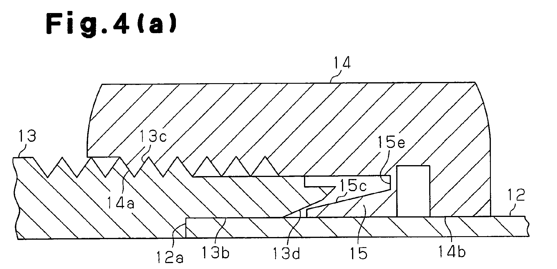

Description
- The present invention relates to a pipe joint for joining, for example, a refrigerant pipe, a refrigeration device using the pipe joint, a heat pump hot water supply device using the pipe joint, a closing valve using the pipe joint, a water supply piping, a method for connecting piping, and an in-the-field piping method.
- A pipe joint with which a pipe is inserted into a joint hole of a joint body and then a nut is screwed into the joint body to connect the pipe to the joint hole of the joint body has been known as a pipe joint used for joining of a pipe through which fluid is made to flow into a refrigerant pipe of a refrigeration device, for example. A flareless joint as disclosed by a prior art of
Patent Document 1 has been frequently adopted as the pipe joint as described above. According to this flareless joint, when a nut is screwed into a joint body, a sleeve is interposed between the joint body and the nut, and the sleeve bites into the outer periphery of the pipe by the screwing, thereby ensuing the sealing performance of the joint portion between the pipe and the joint body. -
Fig. 16 shows the flareless joint disclosed in the prior art ofPatent Document 1. This flareless joint is constructed by ajoint body 101, anut 102, and asleeve 103 provided between thejoint body 101 and thenut 102. When thepipe 104 is joined to thejoint body 101, thesleeve 103 is mounted on the outer peripheral surface 104a of thepipe 104. Thedistal portion 104b of thepipe 104 is inserted into a joint hole 101a of thejoint body 101, and the threadedportion 102a of thenut 102 is engaged with the threadedportion 101b of thejoint body 101. At this time, the proximal end face 103a of thesleeve 103 receives pressing force from apressing face 102b of thenut 102, and thedistal portion 103b of thesleeve 103 receives pressing force from a taper face 101c of thejoint body 101. Therefore, thedistal portion 103b of thesleeve 103 bites into the outer peripheral surface 104a, and thepipe 104 of thepipe 104 is connected to the joint hole 101a of thejoint body 101. As described above, the flareless joint ensures the sealing performance of the joint portion between thepipe 104 and thejoint body 101 by the biting of thesleeve 103 into thepipe 104.
Patent Document 1: Japanese Laid-Open Patent Publication No.2003-74768 - However, the pipe joint as described above is constructed by the joint body, the nut, and the sleeve, and thus there is a risk that a sleeve, which is a relatively small part, may be lost until a pipe is joined. Furthermore, when a pipe is joined, a sleeve, which is a small part, is assembled to the pipe. This can lower the workability. Furthermore, with respect to the sleeve, the site receiving pressing force and the site biting into the pipe are exposed, and thus when the sleeve is stored as a spare or the sleeve is handled, these sites are liable to scratching. This scratching may adversely affect the sealing performance of the joint portion of the pipe joint.
- An objective of the present invention is to provide a pipe joint that prevents loss of a sleeve and ensures the sealing performance of a joint portion while enhancing the workability at the pipe joining operation, a refrigeration device using the pipe joint, etc., a method for connecting piping, etc.
- According to one aspect of the present invention, there is provided a pipe joint having a joint body forming a joint hole to join a pipe, a fastening member fastened to the joint body, and a sleeve biting into the outer periphery of the pipe by fastening of the fastening member to the joint body under the state that the pipe is inserted into the joint hole. The sleeve is integrated with the joint body or the fastening member before the fastening member is fastened to the joint body, and it is cut off and separated from the joint body or the fastening member by the fastening of the fastening member to the joint body.
- According to this construction, the sleeve which bites into the outer periphery of the pipe by the fastening of the fastening member to the joint body is integrated with the joint body or the fastening member before the fastening member is fastened to the joint body. Therefore, the sleeve is prevented from being lost until the pipe is joined as compared with a case where the sleeve is constructed as a separate body from the joint body or the fastening member like the prior art, and thus it is unnecessary to stock a sleeve as a spare. Furthermore, it is unnecessary to assemble the sleeve when the pipe is joined, so that the workability at the pipe connecting operation is enhanced.
- Furthermore, the sleeve is integrated with the joint body or the fastening member, and thus the biting site, etc., of the sleeve is prevented from being exposed from the joint body or the fastening member to the outside. Therefore, when the pipe joint is handled, for example, the biting site of the sleeve into the pipe is prevented from being scratched. Therefore, the sealing performance of the joint portion of the pipe joint is prevented from being degraded by the scratching of the sleeve.
- Since the sleeve is cut off and separated from the joint body or the fastening member by the fastening of the joint member to the joint body, the separated sleeve bites into the outer periphery of the pipe and the pipe is connected to the joint hole of the joint body while ensuring the sealing performance of the joint portion as in the case of the conventional construction.
- According to another aspect of the present invention, there is provided a refrigeration device in which the pipe joint described above is used for the connection portion of a refrigerant pipe. According to this construction, a refrigeration device is provided in which the loss of a sleeve is prevented, and the sealing performance of the joint portion is ensured while enhancing the workability at the pipe joining operation.
- According to a further aspect of the present invention, there is provided a heat pump hot water supply device in which the pipe joint described above is used for the connection portion of a refrigerant pipe. According to this construction, a heat pump hot water supply device is provided in which the loss of a sleeve is prevented, and the sealing performance of the joint portion is ensured while enhancing the workability at the pipe joining operation.
- According to a further aspect of the present invention, there is provided a closing valve in which the pipe joint described above is used for the connection portion of a pipe. According to this construction, a closing valve is provided in which the loss of a sleeve is prevented, and the sealing performance of the joint portion is ensured while enhancing the workability at the pipe joining operation.
- According to a further aspect of the present invention, there is provided a water supply piping in which the pipe joint described above is used for the connection of a pipe. According to this construction, a water supply piping is provided in which the loss of a sleeve is prevented, and the sealing performance of the joint portion is ensured while enhancing the workability at the pipe joining operation.
- According to a further aspect of the present invention, there is provided a piping connecting method for a pipe joint having a joint body having a joint hole formed to join a pipe, a fastening member fastened to the joint body, and a sleeve biting into the outer periphery of the pipe by the fastening of the fastening member to the joint body under the state that the pipe is inserted into the joint hole. Before the fastening member is fastened to the joint body, the sleeve is integrated with the fastening body or the fastening member. The connecting method includes a step of inserting the pipe into the joint hole of the joint body, a step of cutting off and separating the sleeve from the joint body or the fastening member by a fastening operation of the fastening member to the joint body, and a step of making the sleeve bite into the outer periphery of the pipe by the fastening operation of the fastening member to the joint body.
- According to this construction, when the pipe is connected to the pipe joint, the pipe is inserted into the joint hole of the joint body. Subsequently, the sleeve which is integrated with the joint body or the fastening member is cut off from the joint body or the fastening member by the fastening operation of the fastening member to the joint body. Then, the separated sleeve bites into the outer periphery of the pipe by the fastening operation of the fastening member to the joint body, whereby the pipe is connected. As described above, the sleeve is integrated with the joint body or the fastening member, the sleeve is prevented from being lost until the pipe is connected, and the workability at the pipe joining operation is enhanced. Furthermore, the sleeve separated by the fastening operation of the fastening member bites into the outer periphery of the pipe by the fastening operation, and thus a method for connecting piping which ensure the sealing performance of the joint portion is provided.
- According to a further aspect of the present invention, there is provided an in-the-field piping method in which a piping work is carried out at a pipe job site by using the piping connecting method. According to this construction, the piping work is carried out by the fastening operation of the fastening member to the joint body, etc., so that the piping work is safely and easily performed without using any facilities for brazing, etc.
-
-
Fig. 1 is a partial cross-sectional view showing the construction of a pipe joint according to a first embodiment; -
Fig. 2 is a partial cross-sectional view showing a joint body; -
Fig. 3 is a partial cross-sectional view showing a nut; -
Fig. 4 (a) is a cross-sectional view showing a state before a sleeve is cut off,Fig. 4(b) is a cross-sectional view showing a state after the sleeve is separated, andFig. 4(c) is a cross-sectional view showing a state when the sleeve bites into a pipe; -
Fig. 5 is a graph showing a leak amount from the joint portion and a torque coefficient with respect to a biting coefficient; -
Fig. 6(a) is a cross-sectional view showing a state before a sleeve according to a second embodiment is cut off,Fig. 6(b) is a cross-sectional view showing a state after the sleeve is separated, andFig. 6(c) is a cross-sectional view showing a state when the sleeve bites into a pipe; -
Fig. 7(a) is a cross-sectional view showing a state before a sleeve according to a third embodiment is cut off,Fig. 7(b) is a cross-sectional view showing a state after the sleeve is separated, andFig. 7(c) is a cross-sectional view showing a state when the sleeve bites into a pipe; -
Fig. 8(a) is a cross-sectional view showing a state before a sleeve according to a fourth embodiment is cut off,Fig. 8(b) is a cross-sectional view showing a state after the sleeve is separated, andFig. 8(c) is a cross-sectional view showing a state when the sleeve bites into a pipe; -
Fig. 9 is a partial cross-sectional view showing a pipe joint using the construction according to a first embodiment at both ends thereof; -
Fig. 10 is a partial cross-sectional view showing a pipe joint for connecting pipes different in outer diameter by using the construction according to the first embodiment at both ends thereof; -
Fig. 11 is a cross-sectional view showing a pipe joint for connecting a plurality of pipes by using the construction according to the first embodiment; -
Fig. 12 is a diagram showing a connection state of a plurality of pipes and a branch pipe; -
Fig. 13 is a cross-sectional view showing a closing valve using a pipe joint according to the present invention; -
Fig. 14 is a diagram showing a connection state of refrigerant pipes between an indoor unit and an outdoor unit of an air conditioner; -
Fig. 15(a) is a diagram showing a connection state of pipes of a heat pump hot water supply device, andFig. 15(b) is a diagram showing a connection state of pipes of a heat pump hot water supply device according to another example; and -
Fig. 16 is a cross-sectional view showing the construction of a pipe joint of a prior art. - A first embodiment of a pipe joint according to the present invention will be described with reference to
Figs. 1 to 5 . -
Fig. 1 is a partial cross-sectional view showing the construction of a pipe joint. Thepipe joint 1 connectspipes joint body 13 having a cylindrical shape into which thepipes nut 14 as a fastening member threaded with thejoint body 13, and asleeve 15 which is interposed between thejoint body 13 and thenut 14 at the pipe joining operation and has an annular shape. Thepipe 11 is fixed to thejoint body 13, for example, by brazing at asocket portion 13a formed at the distal portion of thejoint body 13. Thedistal portion 12a of thepipe 12 to be connected to thejoint body 13 is inserted into ajoint hole 13b formed at the proximal portion of thejoint body 13. Thedistal portion 15a of thesleeve 15 bites into the outerperipheral surface 12b of thepipe 12 by the thread engagement between thenut 14 and thejoint body 13, whereby thepipe 12 inserted into thejoint body 13 is joined to thejoint body 13. Thesleeve 15 biting into thepipe 12 is integrated with thenut 14 before thepipe 12 is connected, and is cut off and separated from thenut 14 by the thread engagement between thenut 14 and thejoint body 13. The thus constructed pipe joint 1 will be hereafter described in detail. -
Fig. 2 is a partial cross-sectional view showing thejoint body 13. Thejoint body 13 has thesocket portion 13a to which thepipe 11 is fixed, thejoint hole 13b in which thepipe 12 is inserted, anexternal thread portion 13c with which thenut 14 is threaded, aguide face 13d, and anut portion 13e formed on the outer peripheral surface of thejoint body 13. Theguide face 13d guides the outerperipheral surface 15c of thesleeve 15 when thesleeve 15 bites into thepipe 12. - The
socket portion 13a has a circular-hole shape, and has an inner diameter which is substantially equal to the outer diameter of thepipe 11 to be fixed. Thejoint hole 13b has a circular-hole shape, and has an inner diameter D0 which is substantially equal to the outer diameter Dp of thepipe 12 to be inserted. Thesocket portion 13a and thejoint hole 13b communicate with each other through aninner space 13f. Theexternal thread portion 13c has a threaded shape at the place corresponding to thejoint hole 13b and theinner space 13f on the outer peripheral surface of thejoint body 13 so that theexternal thread portion 13c is threaded with thenut 14. Theguide face 13d is located at the proximal portion of thejoint body 13, that is, the inlet of thepipe 12 in thejoint hole 13b, and it expands in diameter from the inner side to the outer side. When thenut 14 is threaded with thejoint body 13, the outerperipheral surface 15c of thesleeve 15 is guided by theguide face 13d, and thesleeve 15 bites into the outerperipheral surface 12b of thepipe 12. Thejoint body 13 is held by thenut portion 13e when thenut 14 is threaded with thejoint body 13. -
Fig. 3 is a partial cross-sectional view showing thenut 14. Thenut 14 has aninternal thread portion 14a to be threaded with theexternal thread portion 13c of thejoint body 13, and a holdinghole 14b for holding the outer periphery of thepipe 12. Thesleeve 15 is integrated with thenut 14. Theinternal thread portion 14a is formed on the inner peripheral surface of the distal portion of thenut 14 which is threaded with thejoint body 13. The holdinghole 14b is formed at the proximal portion of thenut 14, and has a circular-hole shape. Furthermore, the holdinghole 14b has an inner diameter which is substantially equal to the outer diameter Dp of thepipe 12 to be held. Thesleeve 15 of this embodiment is integrally formed with thenut 14, and formed on the inner peripheral surface of the proximal portion of thenut 14. As shown inFig. 3 , the distal end of thesleeve 15 is located in thenut 14, and thesleeve 15 is prevented from being exposed to the outside from thenut 14. Accordingly, thesleeve 15 is prevented from being scratched when thenut 14 is handled. - The
sleeve 15 has an innerperipheral surface 15b facing thepipe 12, an outerperipheral surface 15c as a guided face to be guided by theguide face 13d of thejoint body 13 when thesleeve 15 bites into thepipe 12, and aproximal end face 15d receiving pressing force when thesleeve 15 bites into thepipe 12. - The inner
peripheral surface 15b has an inner diameter which is substantially equal to the outer diameter Dp of thepipe 12. The outerperipheral surface 15c expands in diameter from the distal end to the proximal end of thesleeve 15. An inclination angle β of the outerperipheral surface 15c relative to a line extending in the fastening direction of thenut 14 is set to be smaller than the inclination angle α of theguide face 13d relative to the same line. Accordingly, when thenut 14 is threaded with thejoint body 13, thedistal portion 15a of thesleeve 15 is deformed inward and bites into the outerperipheral surface 12b of thepipe 12. Furthermore, the inclination angle β of the outerperipheral surface 15c is set to be larger than the half angle of the inclination angle α of theguide face 13d. Accordingly, the inclination angle β is prevented from being excessively small, and the pressing force from theguide face 13d is efficiently applied to thesleeve 15. The inclination angle α of theguide face 13d of thejoint body 13 is preferably set in the range from 15° to 30° to smoothly guide thedistal portion 15a of thesleeve 15, and more preferably set in the range from 20° to 25°. Thedistal end 15g of thesleeve 15 biting into thepipe 12 has a sharp-edge shape. Accordingly, thesleeve 15 reliably bites into thepipe 12, and the sealing performance at the biting site at which thesleeve 15 bites into thepipe 12 is enhanced. - The
proximal end face 15d faces acontact portion 14c formed to be nearer to the distal end of thenut 14 than the holdinghole 14b on the inner peripheral surface of thenut 14. Theproximal end face 15d receives the pressing force from thecontact portion 14c after thesleeve 15 is separated from thenut 14, whereby thedistal portion 15a bites into the outerperipheral surface 12b of thepipe 12. As shown inFig. 3 , thesleeve 15 is integrated with thenut 14 at thebase portion 15e thereof. Thebase portion 15e of thesleeve 15 is formed to be thinner. Therefore, thebase portion 15e is cut off, and thesleeve 15 is easily separated from thenut 14. - The
sleeve 15 is formed of a material the hardness of which is equal to or greater than a material of which thepipe 12 is formed. For example, when thepipe 12 is formed of brass, thesleeve 15 is formed of brass or stainless steel, and when thepipe 12 is formed of stainless steel, thesleeve 15 is formed of stainless steel. Accordingly, thesleeve 15 easily bites into thepipe 12, and the sealing performance at the site at which thesleeve 15 bites into thepipe 12 is enhanced. - Next, a method for connecting piping for joining the
pipe 12 to thejoint body 13 by using the pipe joint 1 will be described.Figs. 4(a) to 4(c) are cross-sectional views showing the operation of the surrounding of thesleeve 15 of thepipe joint 1. When thepipe 12 is joined to thejoint body 13, thepipe 12 is first inserted into the holdinghole 14b of thenut 14, and thedistal portion 12a of thepipe 12 is inserted into thejoint hole 13b of thejoint body 13. Then, theinternal thread portion 14a of thenut 14 is threaded with theexternal thread portion 13c of thejoint body 13 as shown inFig. 4(a) under the state that thenut portion 13e of thejoint body 13 is held. - When the
nut 14 is screwed, theguide face 13d of thejoint body 13 abuts against a part of the outerperipheral surface 15c of thesleeve 15, and the pressing force to the outerperipheral surface 15c by theguide face 13d is increased in accordance with the thread engagement of thenut 14. Accordingly, at thebase portion 15e of thesleeve 15, shearing force applied along the screwing direction of thenut 14 is increased, and thebase portion 15e of thesleeve 15 is cut off. At this time, thecut surface 14d of thenut 14 and thecut surface 15f of thesleeve 15 are formed along the thickness direction of thebase portion 15e of thesleeve 15, that is, the screwing direction of thenut 14. As described above, the cut surfaces 14d, 15f are formed along substantially the same direction as the acting direction of the shearing force, and thus thebase portion 15e is easily cut off by the screwing of thenut 14. By cutting off thebase portion 15e of thesleeve 15, thenut 14 and thesleeve 15 are separated from each other as shown inFig. 4(b) . - When the
nut 14 is further screwed, theguide face 13d of thejoint body 13 abuts against a part of the outerperipheral surface 15c of thesleeve 15, and thecontact portion 14c of thenut 14 abuts against theproximal end face 15d of thesleeve 15. Then, in accordance with the screwing of thenut 14, theproximal end face 15d of thesleeve 15 receives pressing force from thecontact portion 14c of thenut 14, and the outerperipheral surface 15c of thesleeve 15 is guided by theguide face 13d of thejoint body 13, whereby thedistal portion 15a of thesleeve 15 bites into the outerperipheral surface 12b of thepipe 12 as shown inFig. 4(c) . - The
cut surface 14d of thenut 14 is distant from thejoint body 13 by aback clearance portion 13g formed on the outer peripheral surface of the proximal portion of thejoint body 13 from the time when thenut 14 and thesleeve 15 are separated from each other until the time when thesleeve 15 bites into thepipe 12. Likewise, thecut surface 15f of thesleeve 15 is distant from thenut 14 by arecess portion 14e formed to be nearer to the distal end of thenut 14 than thecontact portion 14c on the inner peripheral surface of thenut 14. Accordingly, the cut surfaces 14d, 15f are prevented from being brought into contact with thejoint body 13 or thenut 14. Thus thenut 14 is sufficiently screwed into thejoint body 13, so that thesleeve 15 sufficiently bites into thepipe 12. - As described above, the
pipe joint 1 joins thepipe 12 to thejoint body 13 by making thedistal portion 15a of thesleeve 15 bite into the outerperipheral surface 12b of thepipe 12. At this time, the boundary between thedistal portion 15a of thesleeve 15 and the outerperipheral surface 12b of thepipe 12 is hermetically sealed by the biting of thedistal portion 15a of thesleeve 15. Furthermore, the outerperipheral surface 15c of thesleeve 15 and theguide face 13d of thejoint body 13 are brought into close contact with each other, whereby the boundary between the outerperipheral surface 15c of hesleeve 15 and theguide face 13d of thejoint body 13 is hermetically sealed. The sealing performance between thepipe 12 and thejoint body 13 is ensured by the hermetical sealing at these places. - The variation of the sealing performance of the pipe joint 1 in the connecting operation of the
pipe 12 and the variation of the fastening torque applied to thejoint body 13 of thenut 14 with respect to the variation of the shape of thepipe joint 1 and thepipe 12 were measured, and the relationship as shown inFig. 5 was obtained. The abscissa axis ofFig. 5 shows the biting coefficient {Dp - (D0 - 2t)}/Dp, which is set by using the outer diameter Dp of thepipe 12, the inner diameter D0 of thejoint hole 13b of thejoint body 13, and the thickness t in the radial direction of thedistal portion 15a of the sleeve 15 (seeFig. 3 ). (D0 - 2t) shows the inner diameter obtained by subtracting the thickness 2t of the biting site of thesleeve 15 into thepipe 12 from the inner diameter D0 of thejoint hole 13b of thejoint body 13. It can be assumed that thepipe 12 having the outer diameter Dp is inserted into the site having this inner diameter in the joining operation of thepipe 12. Therefore, {Dp - (D0 - 2t)} represents the biting amount of thedistal portion 15a of thesleeve 15 into thepipe 12. The biting coefficient {Dp - (D0 - 2t)}/Dp may be used as a parameter representing the biting ratio of thesleeve 15 to thepipe 12. - X in
Fig. 5 represents the variation of the sealing performance of the pipe joint 1 with respect to the variation of the biting coefficient. The ordinate axis represents the leak amount Q (cc/sec) from the joint portion of thepipe 12. The leak amount Q from the joint portion is obtained by filling thepipe 12 and the pipe joint 1 with helium and measuring the leak amount of helium by a helium leak tester when the pressure of helium is set to 4.2 MPa. The biting coefficient varies because the outer diameter Dp is fixed to ϕ9.52 mm, the inclination angle α is fixed to 20°, the inclination angle β is fixed to 15° and the thickness t is changed in the range from 0.1 to 0.6 mm. With respect to the leak amount Q, as the biting coefficient increases, that is, the biting ratio of thesleeve 15 increases, the leak amount Q decreases as shown in X ofFig. 5 . When the biting coefficient is equal to 0.03 or more, the leak amount Q is equal to substantially zero, and it is equal to a value not more than the measurement limit 10-6 or less of the helium leak tester. - Y of
Fig. 5 represents the variation of the fastening torque of thenut 14 with respect to the variation of the biting coefficient. It is known that the fastening torque T of thenut 14 is proportional to 1.67 square of the outer diameter Dp of thepipe 12. Therefore, the ordinate axis represents the torque coefficient T/Dp1.67 so as to suppress the effect of the difference of the outer diameter Dp on the fastening torque T. The torque coefficient is calculated from a measurement value at which the maximum fastening torque T is obtained when thenut 14 is fastened so that the leak amount Q is minimum. The biting coefficient varies because the outer diameter Dp is fixed to ϕ9.52 mm, the inclination angle α is fixed to 20°, the inclination angle β is fixed to 15° and the thickness t is varied in the range from 0.1 to 0.6 mm. As shown in Y ofFig. 5 , the torque coefficient increases as the biting coefficient increases, that is, as the biting ratio of thesleeve 15 increases. When the biting coefficient is equal to 0.1 or more, that is, the torque coefficient is equal to 1.8 × 10⁵ or more, the torque coefficient falls into a screw breaking area Z in which theexternal thread portion 13c of thejoint body 13 or theinternal thread portion 14a of thenut 14 is highly likely to be broken. -
Fig. 5 shows the variation of the torque coefficient when the outer diameter Dp of thepipe 12 varies and thus the biting coefficient varies. A position P1, at which the outer diameter Dp is equal to ϕ6.35 mm, a position P2, at which the outer diameter Dp is equal to ϕ9.52 mm, a position P3, at which the outer diameter Dp is equal to ϕ12.7 mm, a position P4, at which the outer diameter Dp is equal to ϕ15.88 mm, and a position P5, at which the outer diameter Dp is equal to ϕ19.05 mm are located substantially on the line of Y. This demonstrates that the relationship between the biting coefficient and the torque coefficient varies little even when the outer diameter Dp varies. - From the above measurement results, the shapes of the
pipe joint 1 and thepipe 12 are set so that the biting coefficient satisfies the following equation (1).
- That is, when the biting coefficient is set to 0.02 or more, the leak amount Q from the joint portion of the
pipe 12 is substantially eliminated. When the biting coefficient is set to 0.1 or less, the threaded portion of thejoint body 13 or thenut 14 is prevented from being broken. The relationship between the biting coefficient and the leak amount Q does not vary with respect to the value of the inclination angle α, however, the relationship between the biting coefficient and the torque coefficient varies with respect to the inclination angle α. Therefore, in consideration of the allowance degree of the fastening torque, it is preferable that the biting coefficient ranges from 0.04 to 0.06. By setting the biting coefficient as described above, the sealing performance at the joint portion of thepipe 12 is ensured while preventing the threaded portion of thejoint body 13 or thenut 14 from being broken. - The first embodiment described above has the following advantages.
- (1) In the first embodiment, the
sleeve 15 biting into the outerperipheral surface 12b of thepipe 12 is integrated with thenut 14 before thenut 14 is screwed in thejoint body 13. Therefore, as compared with the case where thesleeve 15 is constructed as a separate body from thenut 14, thesleeve 15 is prevented from being lost until thepipe 12 is joined. Therefore, it is unnecessary to stock thesleeve 15 as a spare. Furthermore, thesleeve 15 is integrated with thenut 14, and thus the work of assembling thesleeve 15 is unnecessary when thepipe 12 is joined to thejoint body 13, so that the workability in the connecting operation of thepipe 12 is enhanced. Thesleeve 15 is cut off from thenut 14 by the thread engagement between thenut 14 and thejoint body 13, and bites into the outerperipheral surface 12b. Therefore, thesleeve 15 is constructed to be easily cut off, and thepipe 12 is joined to thejoint hole 13b of thejoint body 13 while ensuring the sealing performance of the joint portion. - (2) In the first embodiment, the
sleeve 15 is formed on the inner peripheral surface of thenut 14, and the distal end of thesleeve 15 is located in thenut 14. Therefore, thesleeve 15 is prevented from being exposed to the outside from thenut 14, and thesleeve 15 is prevented from being scratched when thenut 14 is handled. Accordingly, thedistal portion 15a or the outerperipheral surface 15c of thesleeve 15 is prevented from being scratched. Thus the sealing performance between thedistal portion 15a of thesleeve 15 and the outerperipheral surface 12b of thepipe 12 or the sealing performance between the outerperipheral surface 15c of thesleeve 15 and theguide face 13d of thejoint body 13 is maintained. - (3) In the first embodiment, the
sleeve 15 is integrally formed with thenut 14. Therefore, the number of parts of thepipe joint 1 is reduced, and the parts management of thepipe joint 1 and the fabrication work of the pipe joint 1 are facilitated.
Furthermore, theexternal thread portion 13c is formed on thejoint body 13, and theinternal thread portion 14a is formed on thenut 14. Thenut 14 is fastened to thejoint body 13 by the thread engagement between theinternal thread portion 14a and theexternal thread portion 13c. Therefore, thesleeve 15 is made to reliably bite into the outer peripheral surface of thepipe 12 by the screwing operation of thenut 14. - (4) In the first embodiment, the cut surfaces 14d, 15f formed by cutting the
base portion 15e of thesleeve 15 are formed along the thickness direction of thebase portion 15e of thesleeve 15, that is, along the screwing direction of thenut 14. Therefore, the direction of the shearing force acting on thebase portion 15e of thesleeve 15 and the direction in which the cut surfaces 14d, 15f are formed are substantially the same, and thebase portion 15e is easily cut by screwing thenut 14. Furthermore, the pressing force is prevented from being applied to the cut surfaces 14d, 15f along the fastening direction of thenut 14, and the nut is prevented from being sufficiently fastened due to a sliding load of the cut surfaces 14d, 15f, etc. Thus thesleeve 15 sufficiently bites into thepipe 12. - (5) In the first embodiment, the
cut surface 14d of thenut 14 is constructed to be distant from thejoint body 13 and thecut surface 15f of thesleeve 15 is constructed to be distant from thenut 14 during the period from the time when thenut 14 and thesleeve 15 are separated from each other until the time whensleeve 15 bites into thepipe 12. Therefore, the cut surfaces 14d, 15f are prevented from contacting thejoint body 13 or thenut 14, so that thenut 14 is sufficiently screwed into thejoint body 13 and thus thesleeve 15 sufficiently bites into thepipe 12. - (6) In the first embodiment, the
sleeve 15 is formed of a material the hardness of which is equal to or higher than that of a material of which thepipe 12 is formed. Therefore, thesleeve 15 easily bites into thepipe 12, and the sealing performance at the biting site at which thesleeve 15 bites into thepipe 12 is enhanced. - (7) In the first embodiment, the
distal end 15g of thesleeve 15 biting into thepipe 12 has a sharp-edge shape. Therefore, thesleeve 15 reliably bites into thepipe 12, and the sealing performance at the biting site at which thesleeve 15 bites into thepipe 12 is enhanced. - (8) In the first embodiment, the
distal portion 15a of thesleeve 15 bites into thepipe 12, and thedistal portion 15a is located at the distal portion of thenut 14. Therefore, thedistal portion 15a is easily deformed by the screwing of thenut 14. - (9) In the first embodiment, the
guide face 13d presses the outerperipheral surface 15c of thesleeve 15, whereby thesleeve 15 bites into thepipe 12. Therefore, thedistal portion 15a of thesleeve 15 is constructed to be gradually deformed in accordance with the screwing of thenut 14. As a result, the screwing torque of thenut 14 is prevented from being excessively large, the nut is reliably fastened and thesleeve 15 is made to reliably bite into thepipe 12. - (10) In the first embodiment, the inclination angle β of the outer
peripheral surface 15c of thesleeve 15 is set to be smaller than the inclination angle α of theguide face 13d of thejoint body 13. Therefore, thedistal portion 15a of thesleeve 15 is easily deformed to thepipe 12. As a result, thesleeve 15 reliably bites into thepipe 12. - (11) In the first embodiment, the inclination angle of the outer
peripheral surface 15c of thesleeve 15 is set to be larger than the half angle of the inclination angle α of theguide face 13d of thejoint body 13. Therefore, the inclination angle β is prevented from being excessively small. Thus the pressing force from theguide face 13d is efficiently transmitted to the outerperipheral surface 15c of thesleeve 15. - (12) In the first embodiment, the shapes of the
pipe joint 1 and thepipe 12 are set so that the biting coefficient ranges from 0.02 to 0.1. If the biting coefficient is set to be equal to 0.02 or more, the biting ratio of thesleeve 15 in the joining operation of thepipe 12 is increased, and the leak amount Q from the joint portion of thepipe 12 is substantially eliminated. If the biting coefficient is set to 0.1 or less, the biting ratio of thesleeve 15 is prevented from increasing more than necessary and thus the threaded portion of thejoint body 13 or thenut 14 is prevented from being broken. Accordingly, the sealing performance at the joint portion of thepipe 12 is ensured while preventing the threaded portion of thejoint body 13 or thenut 14 from being broken. - Next, a pipe joint according to a second embodiment of the present invention will be described with reference to
Figs. 6(a) to 6(c) . In the second embodiment, the construction that the sleeve bites into the outer peripheral surface of the pipe by screwing the nut into the joint body and the pipe is joined to the joint body (seeFig. 1 ) is the same as the first embodiment. In the second embodiment, thesleeve 25 and thenut 24 are not integrated with each other, but thesleeve 25 and thejoint body 23 are integrated with each other. That is, thesleeve 25 is integrated with thejoint body 23 before the joining of thepipe 12, and thesleeve 25 is constructed to be cut off and separated from thejoint body 23 by screwing thenut 24 as the fastening member into thejoint body 23. Furthermore, thesleeve 25 is joined to thejoint body 23 by a method such as adhesion or the like, whereby thesleeve 25 is integrated with thejoint body 23. In the embodiment described below, the overlapping description of the same constructions as the first embodiment is omitted or simplified. -
Figs. 6(a) to 6(c) are cross-sectional views showing the operation of the surrounding of thesleeve 25 of the pipe joint 2 when thepipe 12 is joined to thejoint body 23. As shown inFig. 6(a) , ajoint face 25h located at the proximal portion of thesleeve 25 is formed along the screwing direction of thenut 24, and joined to ajoint face 23h located at the proximal portion of thejoint body 23 by adhesion. Thejoint face 25h of thesleeve 25 may be fitted in thejoint face 23h of thejoint body 23 by press-fitting or the like to join thesleeve 25 to thejoint body 23. By this joint, thesleeve 25 is integrally assembled to thejoint body 23. - A method for connecting piping in which the
pipe 12 is joined to thejoint body 23 by using the pipe joint 2 will be described. When thepipe 12 is joined to thejoint body 23, thepipe 12 is first inserted into the holdinghole 24b of thenut 24, and thedistal portion 12a of thepipe 12 is inserted into thejoint hole 23b of thejoint body 23. Then, as shown inFig. 6(a) , theinternal thread portion 24a of thenut 24 is threaded with theexternal thread portion 23c of thejoint body 23. - When the
nut 24 is screwed into thejoint body 23, thecontact portion 24c of thenut 24 abuts against theproximal end face 25d of thesleeve 25, and the pressing force thereof increases in accordance with the screwing of thenut 24. Accordingly, at thejoint face 25h of thesleeve 25 and thejoint face 23h of thejoint body 23, the shearing force applied in the screwing direction of thenut 24 increases, and thejoint face 25h of thesleeve 25 and thejoint face 23h of thejoint body 23 are cut off from each other. Therefore, the joint faces 25h and 23h constitute a cut surface. The joint faces 25h, 23h are formed along substantially the same direction as the acting direction of the shearing force, and thus the joint faces 25h, 23h are easily cut off by the screwing of thenut 24. By this cutting, thejoint body 23 and thesleeve 25 are separated from each other as shown inFig. 6(b) . - Subsequently, when the
nut 24 is further screwed, theguide face 23d of thejoint body 23 abuts against a part of the outerperipheral surface 25c of thesleeve 25, and thecontact portion 24c of thenut 24 abuts against theproximal end face 25d of thesleeve 25. Then, theproximal end face 25d of thesleeve 25 receives pressing force from thecontact portion 24c of thenut 24 in accordance with the screwing of thenut 24, and the outerperipheral surface 25c of thesleeve 25 is guided by theguide face 23d of thejoint body 23, whereby thedistal portion 25a of thesleeve 25 bites into the outerperipheral surface 12b of thepipe 12 as shown inFig. 6(c) . - As described above, in the
pipe joint 2, thedistal portion 25a of thesleeve 25 bites into the outerperipheral surface 12b of thepipe 12, whereby thepipe 12 is connected to thejoint body 23 while ensuring the sealing performance between thepipe 12 and thejoint body 23. - The second embodiment has the following advantages in addition to the advantages (6) to (12) of the first embodiment.
- (13) The
sleeve 25 of the second embodiment is integrated with thejoint body 23 before thenut 24 is screwed into thejoint body 23. Therefore, as in the case of the first embodiment, the loss of thesleeve 25 before thepipe 12 is joined is prevented, and thus it is unnecessary to stock thesleeve 25 as a spare. Furthermore, the work of assembling thesleeve 25 when thepipe 12 is joined to thejoint body 23 is unnecessary, and thus the workability at the connecting operation of thepipe 12 is enhanced. Thesleeve 25 is cut off from thejoint body 23 and bites into the outerperipheral surface 12b of thepipe 12 by the thread engagement between thenut 24 and thejoint body 23. Therefore, thesleeve 25 is easily cut off, and also thepipe 12 is joined to thejoint hole 23b of thejoint body 23 while ensuring the sealing performance of the joint portion.
Furthermore, theexternal thread portion 23c is formed on thejoint body 23, and theinternal thread portion 24a is formed on thenut 24. Thenut 24 is fastened to thejoint body 23 so that theinternal thread portion 24a is threaded with theexternal thread portion 23c. Therefore, thesleeve 25 reliably bites into the outer peripheral surface of thepipe 12 by the screwing operation of thenut 24. - (14) The
sleeve 25 of the second embodiment is joined to thejoint body 23 and integrally assembled to thejoint body 23 by adhesion, fitting or other methods. Therefore, in such a case that it is difficult to form thesleeve 25 and thejoint body 23 integrally, thesleeve 25 and thejoint body 23 can be integrated with each other. Accordingly, thesleeve 25 and thejoint body 23 can be integrated with each other while considering the performance of the forming of thesleeve 25 and thejoint body 23. - (15) In the second embodiment, the
joint face 23h of thejoint body 23 and thejoint face 25h of thesleeve 25 are formed along the screwing direction of thenut 24. Therefore, the direction of the shearing force applied by the screwing of thenut 24 and the direction of the joint faces 25h, 23h are substantially the same, and the joint faces 25h and 23h are easily cut off by the screwing of thenut 24. Furthermore, the pressing force is prevented from being applied to the joint faces 25h, 23h along the fastening direction of thenut 24. Thus, thenut 24 is sufficiently fastened due to the sliding load of the joint faces 25h, 23h or the like and thus thesleeve 25 sufficiently bites into thepipe 12. - (16) In the second embodiment, the
joint face 23h of thejoint body 23 is constructed to be distant from thenut 24, and thejoint face 25h of thesleeve 25 is constructed to be distant from thejoint body 23 during the period from the time when thejoint body 23 and thesleeve 25 are separated from each other until the time when thesleeve 25 bites into thepipe 12. Accordingly, the joint faces 25h, 23h are prevented from coming into contact with thejoint body 23 or thenut 24. Thus, thenut 24 is sufficiently screwed into thejoint body 23, and thesleeve 25 sufficiently bites into thepipe 12. - Next, a pipe joint according to a third embodiment of the present invention will be described with reference to
Figs. 7(a) to 7(c) . In the first and second embodiments, the pipe is joined to the joint body by the thread engagement between the nut and the joint body. In contrast, in the third embodiment and a fourth embodiment described below, the pipe is joined to the joint body without using any screw structure between the joint body and the nut. In the pipe joints according to the third and fourth embodiments, the sleeve is integrated with the fastening member. The sleeve is cut off from the fastening member by the sliding movement of the fastening member in the axial direction of the pipe, and the separated sleeve bites into the outer peripheral surface of the pipe. The overlapping description of the same constructions as the first embodiment such as the construction that the sleeve bites into the outer peripheral surface of the pipe, etc., is omitted or simplified. -
Figs. 7(a) to 7(c) are cross-sectional views showing the operation of the pipe joint 5 when thepipe 12 is joined to thejoint body 53.Fig. 7(a) shows a state before thepipe 12 is connected by thepipe joint 5. As shown inFig. 7(a) , thepipe joint 5 has ajoint body 53 in which thepipe 12 is inserted, afastening member 54 fastened to thejoint body 53, and asleeve 55 biting into the outer peripheral surface of thepipe 12. Thesleeve 55 is integrally formed with thefastening member 54, and thesleeve 55 and thefastening member 54 are joined to each other through abase portion 55e. - A plurality of operating levers 56 are rotatably supported on the outer peripheral surface of the
joint body 53. The pivot shaft 56a of each operatinglever 56 is formed so as to extend in a direction substantially orthogonal to the axis of thejoint body 53. An engaginglever 57 is rotatably supported at the middle portion of each operatinglever 56. Apivot shaft 57a of the engaginglever 57 is disposed so as to extend parallel to the pivot shaft 56a of the operatinglever 56. An engagingpawl 57b formed at the distal end of the engaginglever 57 is designed so as to be hooked to a projectingportion 54f formed on the outer peripheral surface of thefastening member 54. Furthermore, a sliding face 53i having a circular shape is formed on the outer peripheral surface of the proximal portion of thejoint body 53. A sliding face 54i having a circular shape is formed on the inner peripheral surface of the distal portion of thefastening member 54. When thefastening member 54 is fastened to thejoint body 53, the sliding face 53i is fitted to the sliding face 54i. Thefastening member 54 is designed to be movable in only the axial direction of thejoint body 53. - Next, the pipe connecting method for connecting the
pipe 12 to thejoint body 53 by using the pipe joint 5 will be described. When thepipe 12 is joined to thejoint body 53, thepipe 12 is inserted into the holdinghole 54b of thefastening member 54, and thedistal portion 12a of thepipe 12 is inserted into thejoint hole 53b of thejoint body 53. As shown inFig. 7(a) , the operatinglever 56 is rotated to the distal end of the joint body 53 (in the direction as indicated by arrow R ofFig. 7(a) ) under the state that the engagingpawl 57b of the engaginglever 57 is hooked to the projectingportion 54f of thefastening member 54. - When the operating
lever 56 is rotated in the direction indicated by arrow R, thefastening member 54 is moved to thejoint body 53, so that theguide face 53d of thejoint body 53 abuts against a part of the outerperipheral surface 55c of thesleeve 55, and the pressing force thereof increases as thefastening member 54 moves. Accordingly, at thebase portion 55e of thesleeve 55, the shearing force applied in the moving direction of thefastening member 54 increases, and thebase portion 55e of thesleeve 55 is cut off. Then, as shown inFig. 7(b) , thefastening member 54 is separated from thesleeve 55. - When the operating
lever 56 is further rotated in the direction indicated by arrow R, thefastening member 54 is further moved to thejoint body 53, so that theguide face 53d of thejoint body 53 abuts against a part of the outerperipheral surface 55c of thesleeve 55, and the contact portion 54c of thefastening member 54 abuts against the proximal end face 55d of thesleeve 55. Then, in accordance with the movement of thefastening member 54, the proximal end face 55d of thesleeve 55 receives pressing force from the contact portion 54c of thefastening member 54, and the outerperipheral surface 55c of thesleeve 55 is guided by theguide face 53d of thejoint body 53, whereby thedistal portion 55a of thesleeve 55 bites into the outerperipheral surface 12b of thepipe 12 as shown inFig. 7(c) . - As described above, in the
pipe joint 5, thedistal portion 55a of thesleeve 55 bites into the outerperipheral surface 12b of thepipe 12, whereby thepipe 12 is joined to thejoint body 53 while ensuring the sealing performance between thepipe 12 and thejoint body 53. - The third embodiment described above has the following advantages.
- (17) In the third embodiment, the
fastening member 54 is fastened to thejoint body 53 by operating the operatinglever 56. The sleeve which is integrated with thefastening member 54 is cut off from thefastening member 54, and bites into the outer periphery of thepipe 12, whereby thepipe 12 is joined to thejoint body 53. Therefore, even when no screwing structure is adopted between thejoint body 53 and thefastening member 54, the same advantages as the advantages (1), (2) and (4) to (12) of the first embodiment are obtained. - Next, a fourth embodiment of the pipe joint according to the present invention will be described with reference to
Figs. 8(a) to 8(c) . As in the case of the third embodiment, the pipe joint according to the fourth embodiment is designed so that the fastening member is slid in the axial direction of the pipe at the pipe joining operation. The overlapping description of the same constructions as the first embodiment such as the construction that the sleeve bites into the outer peripheral surface of the pipe, etc., is omitted or simplified. -
Figs. 8(a) to 8(c) are cross-sectional views showing the operation of the pipe joint 6 when thepipe 12 is joined to thejoint body 63.Fig. 8(a) shows a state before thepipe 12 is connected by thepipe joint 6. As shown inFig. 8(a) , thepipe joint 6 has ajoint body 63 in which thepipe 12 is inserted, afastening member 64 to be fastened to thejoint body 63, and asleeve 65 biting into the outer peripheral surface of thepipe 12. Thesleeve 65 is integrally formed with thefastening member 64, and thesleeve 65 and thefastening member 64 are joined to each other through abase portion 65e. - A plurality of
flange portions 63j are formed on the outer peripheral surface of thejoint body 63. Acoupling hole 63k extending along the fastening direction of thefastening member 64 is formed in eachflange portion 63j. A flange portion 64j is formed so as to face eachflange portion 63j of thejoint body 63 on the outer peripheral surface of thefastening member 64. Acoupling hole 64k is formed in each flange portion 64j so as to be coaxial with thecoupling hole 63k. A slidingface 63m having a circular shape is formed on the outer peripheral surface of the proximal portion of thejoint body 63. A sliding face 64m having a circular shape is formed on the inner peripheral surface of the distal portion of thefastening member 64. When thefastening member 64 is fastened to thejoint body 63, the slidingface 63m is fitted to the sliding face 64m. Thefastening member 64 is designed so as to be movable only in the axial direction of thejoint body 63. - Next, the pipe connecting method for joining the
pipe 12 to thejoint body 63 by using the pipe joint 6 will be described. When thepipe 12 is joined to thejoint body 63, thepipe 12 is first inserted into the holdinghole 64b of thefastening member 64, and thedistal portion 12a of thepipe 12 is inserted into thejoint hole 63b of thejoint body 63. Then, as shown inFig. 8(a) , abolt 66 is inserted into thecoupling hole 63k of thejoint body 63 and thecoupling hole 64k of thefastening member 64, and thenut 67 is fastened to thebolt 66. - When the
nut 67 is fastened, thefastening member 64 is moved to thejoint body 63, so that theguide face 63d of thejoint body 63 abuts against a part of the outerperipheral surface 65c of thesleeve 65 and the pressing force thereof increases as thefastening member 64 moves. Accordingly, at thebase portion 65e of thesleeve 65, the shearing force applied in the moving direction of thefastening member 64 increases, and thebase portion 65e of thesleeve 65 is cut off. Then, as shown inFig. 8(b) , thefastening member 64 and thesleeve 65 are separated from each other. - When the
nut 67 is further fastened, thefastening member 64 is further moved to thejoint body 63, so that theguide face 63d of thejoint body 63 abuts against a part of the outerperipheral surface 65c of thesleeve 65, and also the contact portion 64c of thefastening member 64 abuts against theproximal end face 65d of thesleeve 65. Then, in accordance with the movement of thefastening member 64, theproximal end face 65d of thesleeve 65 receives pressing force from the contact portion 64c of thefastening member 64, and the outerperipheral surface 65c of thesleeve 65 is guided by theguide face 63d of thejoint body 63, whereby thedistal portion 65a of thesleeve 65 bites into the outerperipheral surface 12b of thepipe 12 as shown inFig. 8(c) . - As described above, according to the
pipe joint 6, thedistal portion 65a of thesleeve 65 bites into the outerperipheral surface 12b of thepipe 12, whereby thepipe 12 is joined to thejoint body 63 while ensuring the sealing performance between thepipe 12 and thejoint body 63. - The fourth embodiment described above has the following advantages.
- (18) In the fourth embodiment, the
nut 67 is fastened to thebolt 66, whereby thefastening member 64 is fastened to thejoint body 63. Thesleeve 65 which is integrated with thefastening member 64 is cut off from thefastening member 64 and bites into the outer periphery of thepipe 12, so that thepipe 12 is joined to thejoint body 63. Therefore, the same advantages as the advantages (1), (2) and (4) to (12) of the first embodiment are obtained without using the screwing structure between thejoint body 63 and thefastening member 64. - Each of the embodiments may be modified as follows.
- In the first, third, and fourth embodiments, the
sleeve 15 is integrally formed with thenut 14. However, the present invention is not limited to this construction. Thesleeve 15 may be joined to thenut 14 by adhesion, fitting or other methods. Furthermore, in the second embodiment, thesleeve 25 is joined to thejoint body 23 by adhesion, fitting or other methods and integrated with thejoint body 23. However, the present invention is not limited to this construction, and thesleeve 25 may be integrally formed with thenut 24. - In the first and second embodiments, the cut surfaces 14d, 15f and the joint faces 23h, 25h are formed along the screwing direction of the nuts 14, 24. However, this invention is not limited to this structure, and the cut surfaces 14d, 15f and the joint faces 23h, 25h may be formed along a direction other than the screwing direction of the nuts 14, 24 as long as the
sleeves - In the first and second embodiments, the cut surfaces 14d, 15f and the joint faces 23h, 25h are distant from the
joint bodies sleeves sleeves pipe 12. However, the present invention is not limited to this construction, and the cut surfaces 14d, 15f and the joint faces 23h, 25h may be brought into contact with thejoint bodies sleeves pipe 12. - In the first to fourth embodiments, the
distal portions sleeves peripheral surface 12b of the pipe in the joining operation of thepipe 12. However, the present invention is not limited to this construction, and a site other than thedistal portion sleeve peripheral surface 12b of thepipe 12. - In the first to fourth embodiments, the distal end of the
distal portion pipe 12 has a sharp-edge shape. However, the present invention is not limited to this construction, and the distal end of thedistal portion sleeve pipe 12 is ensured. - In the first to fourth embodiments, the inclination angle β of the outer
peripheral surface guide face - In the first to fourth embodiments, the
sleeve pipe 12 is formed. However, the present invention is not limited to this construction, and thesleeve pipe 12 is formed as long as the sealing performance at the biting site of thesleeve pipe 12 is ensured. - In the first to fourth embodiments, the
pipe 11 inserted into the socket portion of the joint body is fixed to the joint body by brazing, and thepipe 12 inserted into the joint hole is joined to the joint body by the fastening of the sleeve or the fastening member. However, the present invention is not limited to this construction, and the pipes located at both distal portion and proximal portion of the joint body may be joined to the joint body by the fastening of the sleeve or the fastening member. -
Fig. 9 is a partial cross-sectional view showing the pipe joint 7 in which the construction of the first embodiment is applied to both distal portion and proximal portion of the joint body.Joint holes joint body 73, and thepipes joint holes sleeve 75 which is integrated with thenut 74 is cut off from thenut 74 and bites into the outer peripheries of thepipes nut 74 and thejoint body 73, whereby thepipes joint body 73. According to this construction, for example, in a case where equipment disposed on thepipes pipes cut pipes pipe joint 7, thepipes - Furthermore, the respective pipes different in outer diameter may be connected to the distal portion and proximal portion of the pipe joint.
Fig. 10 is a partial cross-sectional view showing the pipe joint 8 in which respective pipes different in outer diameter are constructed to be connectable to each other by using the construction of the first embodiment for the distal portion and proximal portion of the pipe joint. Apipe 81 is inserted into ajoint hole 83a formed at the distal portion of ajoint body 83. The inner diameter of thejoint hole 83b formed at the proximal portion of thejoint body 83 is set to be smaller than the inner diameter of thejoint hole 83a. Apipe 82 having an outer diameter smaller than the outer diameter of thepipe 81 is inserted into thejoint hole 83b.Sleeves pipes joint body 83. Then, thepipes joint body 83. In this construction, thepipe joint 8 is preferably used when the diameters of thepipes pipes - In the first to fourth embodiments, the pipe joint is designed so that two
pipes Fig. 11 is a cross-sectional view showing a pipe joint in which four pipes are connected to one another by using the construction of the first embodiment. The pipe joint 9 is designed so that fluid flowing from afirst port 91 is branched to second tofourth ports Pipes joint holes respective pipes respective ports nut 14 and thesleeve 15 of the pipe joint 1 according to the first embodiment. In this construction, when a plurality of indoor units are connected to an outdoor unit of an air conditioner, the pipe joint 9 is suitably used at a place where refrigerant is branched or confluent. In the pipe joint in which a plurality of pipes are connected to one another, at least one pipe is connected by the construction of the first embodiment, and all the pipes may be connected by the construction of the first embodiment. - Furthermore, when three or more pipes are connected, the pipe joint of the first to fourth embodiments or the pipe joints 7, 8 may be used together with a branch pipe by which the flow path is branched to a plurality of paths.
Fig. 12 is a diagram showing a connection state between abranch pipe 99 andpipes 100. Thebranch pipe 99 is designed so that the flow path is branched to a plurality of paths, and the end portions of thebranch pipe 99 are connected to thepipes 100 by the pipe joints 7, 8, respectively. In this construction, thepipes 100 are branched or thepipes 100 join together while ensuring the sealing performance at the joint portion of thepipes 100. In a case where the construction of the pipe is changed so that fluid flowing in the pipe is branched or confluent, thebranch pipe 99 and the pipe joints 7, 8 are suitably used when a pipe is cut at a construction site to dispose a branch pipe and then a pipe to be newly connected, the cut pipe and the branch pipe are connected. - In the first to fourth embodiments, the type of fluid flowing through the pipe is not particularly limited. A pipe through which supercritical refrigerant used under a supercritical state flows may be connected by the pipe joint of the first to fourth embodiments. In this construction, even when high pressure is applied to the joint portion between the pipe joint and the pipe because supercritical refrigerant used under the supercritical state flows into the pipe, the sealing performance at the joint portion between the pipe joint and the pipe is ensured, so that the leakage of refrigerant at the joint portion is suitably prevented.
- Furthermore, a pipe through which carbon dioxide refrigerant flows may be connected by the pipe joint according to the first to fourth embodiment. In this construction, fluid flowing in the pipe to be connected is carbon dioxide refrigerant, and thus a pipe circuit using the pipe joint is constructed in consideration of the global environment. Furthermore, even when carbon dioxide refrigerant is used under the supercritical state and thus high pressure is applied to the joint portion between the pipe joint and the pipe, the sealing performance of the joint portion between the pipe joint and the pipe is ensured, so that leakage of the refrigerant at the joint portion is suitably prevented.
- Still furthermore, a pipe through which hydrocarbon refrigerant flows may be connected by the pipe joint of the first to fourth embodiment. In this construction, the fluid flowing in the pipe to be connected is hydrocarbon refrigerant such as propane, isobutene or the like, and thus the pipe circuit using the pipe joint is constructed in consideration of the global environment. Furthermore, the sealing performance at the joint portion between the pipe joint and the pipe is ensured, and thus leakage of hydrocarbon refrigerant having a high inflammability from the joint portion is suitably prevented.
- In the first to fourth embodiments, the pipe joint is used to connect the
pipe 11 and thepipe 12. However, the present invention is not limited to this construction, and the construction of the pipe joint may be used for a connecting portion of a closing valve which is disposed in a refrigerant pipe of an air conditioner, for example.Fig. 13 is a cross-sectional view showing a closing valve 31 using the construction of the pipe joint 1 according to the first embodiment. The closing valve 31 has ahousing 32 including first tofourth cylinder portions first port 33 and asecond port 34 to which a pipe is joined are formed in thefirst cylinder portion 32a and thesecond cylinder portion 32b, respectively. Aservice port 35 is formed in thethird cylinder portion 32c. The closing valve 31 is designed to perform vacuuming of the inside of the pipe, charge refrigerant, etc., by operating avalve body 37 of avalve core 36. A substantiallycylindrical valve body 38 is disposed in thefourth cylinder portion 32d, and thefirst port 33 and thesecond port 34 are made to communicate with each other or the communication therebetween is interrupted by operating thevalve body 38. In the thus constructed closing valve 31, the construction of thepipe joint 1 of the first embodiment is applied to thefirst port 33. That is, the construction of thejoint body 13 of thepipe joint 1 is used for thehousing 32 of the closing valve 31, and thepipe 12 inserted into thefirst port 33 is joined by thenut 14 and thesleeve 15. Accordingly, the closing valve 31 having the advantages of the pipe joint described above is obtained. - In the first to fourth embodiments, the
pipe 11 and thepipe 12 are connected to each other by the pipe joint, however, these constructions of the pipe joint may be applied to theconnection portions refrigerant pipes 44 through which anindoor unit 42 and anoutdoor unit 43 of anair conditioner 41 as shown inFig. 14 communicate with each other. In theair conditioner 41 as described above, the pipe joints of the first to fourth embodiments are used for theconnection portions 45 to which theindoor unit 42 and therefrigerant pipes 44 are connected, thereby joining therefrigerant pipes 44. The closing valves 31 may be used for theconnection portions 46 to which theoutdoor unit 43 and therefrigerant pipes 44 are connected, thereby joining therefrigerant pipes 44. The pipes may be connected by using thepipe joint refrigerant pipe 44. When a plurality ofindoor units 42 are provided, the pipe joint 9 may be used at some midpoint of therefrigerant pipe 44 so that the pipe is branched or pipes join together. The construction of the pipe joint of the first to fourth embodiment may be applied not only to theair conditioner 41, but also to the connection portion of a refrigerant pipe in another refrigeration device. Accordingly, a refrigeration device having the advantages of the pipe joint described above is obtained. - The construction of the pipe joint of the first to fourth embodiments may be applied to the connection portion of the pipe of a heat pump hot water supply device.
Figs. 15(a) and 15(b) are diagrams showing connection states of pipes of the heat pump hot water supply device.Fig. 15(a) is a diagram showing the heat pump hotwater supply device 111 having one tank. The heat pump hotwater supply device 111 has aheat pump unit 121 for pumping up heat from the outside air, and a hotwater storage unit 131 for supplying hot water by using the heat pumped up by theheat pump unit 121. Theheat pump unit 121 includes a refrigeration cycle apparatus having anexpansion valve 122, anair heat exchanger 123, acompressor 124, and awater heat exchanger 125. Refrigerant flows in therefrigerant pipe 126 to which each equipment is connected. The hotwater storage unit 131 is constructed as follows. That is, water supplied to atank 133 via awater supply piping 132 is circulated between thetank 133 and thewater heat exchanger 125 by apump 134. Hot water heat exchanged in thewater heat exchanger 125 is supplied from thetank 133 via thewater supply piping 135. -
Fig. 15(b) is a diagram showing the heat pump hotwater supply device 112 having two tanks. The heat pump hotwater supply device 112 has the same construction as the heat pump hotwater supply device 111. However, thefirst tank 142 and thesecond tank 143 corresponding to the tank of the hotwater storage unit 141 are connected to each other in series. The heat pump hotwater supply device 112 is added with an additional heating function constructed as follows. That is, hot water stored in thefirst tank 142 and asecond tank 143 is circulated between the first andsecond tanks heating heat exchanger 144 by apump 145. Hot water fed from atub 146 via a water supply piping 147 to a pump 148 is subjected to heat exchange and warmed by the additionalheating heat exchanger 144, and then returned to thetub 146 via thewater supply piping 149. - In the heat pump hot
water supply devices connection portion 127 provided to therefrigerant pipe 126 and theconnection portion 136 provided to thewater supply pipings water supply device 112, the pipe joint of the first to fourth embodiments may be used for theconnection portion 150 provided to thewater supply piping 147, 149. Accordingly, the heat pump hotwater supply device connection portion - Still furthermore, a piping work may be carried out at a job site of the
air conditioner 41 or the heat pump hotwater supply device
Claims (28)
- A pipe joint comprising:a joint body having a joint hole formed to join a pipe;a fastening member fastened to the joint body; anda sleeve biting into an outer periphery of the pipe by the fastening of the fastening member to the joint body under a state in which the pipe is inserted into the joint hole,the pipe joint being characterized in that the sleeve is integrated with the joint body or the fastening member before the fastening member is fastened to the joint body, and cut off and separated from the joint body or the fastening member by the fastening of the fastening member to the joint body.
- The pipe joint according to claim 1, characterized in that a threaded portion is formed in the joint body, and the fastening member is threaded with the threaded portion to be fastened to the joint body.
- The pipe joint according to claim 1 or 2, characterized in that the sleeve is integrally formed with the joint body or the fastening member.
- The pipe joint according to claim 1 or 2, characterized in that the sleeve is joined to the joint body or the fastening member to be integrally assembled.
- The pipe joint according to any one of claims 1 to 4, characterized in that the fastening member has a cylindrical shape, and the sleeve is integrated with the fastening member on an inner surface of the fastening member, a distal end of the sleeve being located in the fastening member.
- The pipe joint according to any one of claims 1 to 5,
characterized in that a cut surface generated by cutting the sleeve is formed along substantially the same direction as the fastening direction of the fastening member. - The pipe joint according to any one of claims 1 to 6, characterized in that a cut surface generated by cutting the sleeve is provided so as to be distant from the joint body or the fastening member when the fastening member is fastened to the joint body and thus the sleeve bites into the pipe.
- The pipe joint according to any one of claims 1 to 7, characterized in that the sleeve is formed of a material the hardness of which is equal to or higher than that of a material of which the pipe is formed.
- The pipe joint according to any one of claims 1 to 8, characterized in that a distal end of a site of the sleeve at which the sleeve bites into the pipe has a sharp-edge shape.
- The pipe joint according to any one of claims 1 to 9, characterized in that the distal portion of the sleeve bites into the pipe.
- The pipe joint according to claim 10, characterized in that the sleeve has an annular shape, and a thickness t in the radial direction at the distal portion of the sleeve, an outer diameter Dp of the pipe, and an inner diameter D0 of the joint hole of the joint body satisfy the following relationship:

- The pipe joint according to any one of claims 1 to 11, characterized in that a guide face expanding in diameter from the inside to the outside is formed on the inner surface of the joint hole, wherein the sleeve has an annular shape, a guided face expanding in diameter from the distal end of the sleeve to the base of the sleeve is formed on the outer peripheral surface of the sleeve, and wherein the guide face presses the guided face, whereby the sleeve bites into the pipe.
- The pipe joint according to claim 12, characterized in that an inclination angle of the guided face with respect to a line extending along a fastening direction of the fastening member is set to be smaller than an inclination angle of the guide face with respect to the line.
- The pipe joint according to claim 13, characterized in that the inclination angle of the guided face is set to be larger than the half angle of the inclination angle of the guide face.
- The pipe joint according to any one of claims 1 to 14, characterized in that the joint body has a plurality of joint holes for joining a plurality of pipes, and a pipe inserted into at least one joint hole is joined by the biting of the sleeve into the pipe.
- The pipe joint according to claim 15, characterized in that the joint body has two joint holes for joining a pipe, and a pipe inserted into one joint hole is joined by the biting of the sleeve into the pipe, and a pipe inserted into the other joint hole is joined by brazing.
- The pipe joint according to claim 15, characterized in that the joint body has two joint holes for joining pipes, and pipes inserted into both joint holes are joined to each other by the biting of the sleeve into the pipes.
- The pipe joint according to any one of claims 15 to 17,
characterized in that pipes having at least two kinds of outer diameters are joined to each other. - The pipe joint according to any one of claims 1 to 18, characterized in that the pipe to be joined is a branch pipe having a flow path branched to a plurality of paths.
- The pipe joint according to any one of claims 1 to 19, characterized in that a pipe in which supercritical refrigerant used under a supercritical state flows is connected.
- The pipe joint according to any one of claims 1 to 19, characterized in that a pipe in which carbon dioxide refrigerant flows is connected.
- The pipe joint according to any one of claims 1 to 19, characterized in that a pipe in which hydrocarbon refrigerant flows is connected.
- A refrigeration device characterized by using the pipe joint according to any one of claims 1 to 22 as a connection portion of a refrigerant pipe.
- A heat pump hot water supply device characterized by using the pipe joint according to any one of claims 1 to 22 as a connection portion of a refrigerant pipe.
- A closing valve characterized by using the pipe joint according to any one of claims 1 to 19 as a connection portion of a pipe.
- A water supply piping characterized by using the pipe joint according to any one of claims 1 to 19 as a connection portion of a pipe.
- A method for connecting piping using a pipe joint comprising a joint body having a joint hole formed to join a pipe, a fastening member fastened to the joint body, and a sleeve which bites into an outer periphery of the pipe by the fastening of the fastening member to the joint body under a state where the pipe is inserted into the joint hole, and is integrated with the joint body or the fastening member before the fastening member is fastened to the joint body, the method being characterized by:inserting the pipe into the joint hole of the joint body;cutting off and separating the sleeve from the joint body or the fastening member by a fastening operation of the fastening member to the joint body; andmaking the sleeve bite into the outer periphery of the pipe by the fastening operation of the fastening member to the joint body.
- A in-the field piping method characterized in that a piping work is carried out at a job site of the piping work by using the method for connecting piping according to claim 27.
Applications Claiming Priority (3)
| Application Number | Priority Date | Filing Date | Title |
|---|---|---|---|
| JP2005289209 | 2005-09-30 | ||
| JP2006023471A JP3940850B2 (en) | 2005-09-30 | 2006-01-31 | Pipe fittings, refrigeration equipment, heat pump water heater, shut-off valve, water supply piping, piping connection method, and local piping construction method |
| PCT/JP2006/319456 WO2007037367A1 (en) | 2005-09-30 | 2006-09-29 | Pipe joint, refrigeration device, heat pump hot water supply device, closing valve, water supply piping, method of connecting piping, and in-the-field piping method |
Publications (1)
| Publication Number | Publication Date |
|---|---|
| EP1930641A1 true EP1930641A1 (en) | 2008-06-11 |
Family
ID=37899788
Family Applications (1)
| Application Number | Title | Priority Date | Filing Date |
|---|---|---|---|
| EP06798448A Withdrawn EP1930641A1 (en) | 2005-09-30 | 2006-09-29 | Pipe joint, refrigeration device, heat pump hot water supply device, closing valve, water supply piping, method of connecting piping, and in-the-field piping method |
Country Status (8)
| Country | Link |
|---|---|
| US (1) | US7971909B2 (en) |
| EP (1) | EP1930641A1 (en) |
| JP (1) | JP3940850B2 (en) |
| KR (1) | KR20080024243A (en) |
| CN (1) | CN101268299B (en) |
| AU (1) | AU2006295825A1 (en) |
| TW (1) | TW200726935A (en) |
| WO (1) | WO2007037367A1 (en) |
Families Citing this family (15)
| Publication number | Priority date | Publication date | Assignee | Title |
|---|---|---|---|---|
| JP5023721B2 (en) * | 2006-01-31 | 2012-09-12 | ダイキン工業株式会社 | Bite-type pipe connection structure |
| JP5012118B2 (en) * | 2007-03-19 | 2012-08-29 | ダイキン工業株式会社 | Bite type fittings, refrigeration equipment and hot water equipment |
| JP2009019652A (en) * | 2007-07-10 | 2009-01-29 | Shigeo Kawasaki | Pipe joint |
| WO2009025796A2 (en) * | 2007-08-21 | 2009-02-26 | King Lloyd Herbert Jr | Leak proof pipe connections and leak proofing pipe connections |
| JP5266956B2 (en) | 2007-09-11 | 2013-08-21 | ダイキン工業株式会社 | Dual-use pipe joint, dedicated tool for this dual-use pipe joint, refrigeration equipment, separation type air conditioner |
| KR100950219B1 (en) * | 2008-05-29 | 2010-03-29 | 주식회사 중앙씨엠아이 | Pipe Assemblies Provide Compact Connection Structures |
| JP4557081B2 (en) * | 2009-01-21 | 2010-10-06 | ダイキン工業株式会社 | Biting type pipe connection structure, valve, biting type pipe fitting and refrigeration system |
| WO2013067471A1 (en) * | 2011-11-04 | 2013-05-10 | Saint-Gobain Performance Plastics Corporation | System, method and apparatus for plumbing fitting with removable sampling valve |
| FR3003330B1 (en) * | 2013-03-18 | 2015-07-17 | Arkema France | PLUNGER TUBE CONNECTION DEVICE FOR A PACKAGING CONTAINER OF A PRODUCT, IN PARTICULAR A CHEMICAL |
| WO2015187958A1 (en) | 2014-06-04 | 2015-12-10 | Parker-Hannifin Corporation | Compression fitting with torque nut |
| CN107923558B (en) * | 2015-08-28 | 2019-08-27 | 株式会社富士金 | Pipe joint, fluid controller, fluid control device, semiconductor manufacturing apparatus, and method of manufacturing a pipe joint |
| US10648598B2 (en) | 2016-02-09 | 2020-05-12 | Swagelok Company | Ferrule for a conduit fitting |
| US10563570B2 (en) | 2017-08-29 | 2020-02-18 | Caterpillar Inc. | High temperature capable joint assembly for use in air-to-air aftercoolers (ATAAC) |
| WO2019210016A1 (en) | 2018-04-27 | 2019-10-31 | Swagelok Company | Ferrule assembly for conduit fitting |
| US20260002714A1 (en) * | 2024-07-01 | 2026-01-01 | Vertiv Corporation | Cascade refrigerant line set |
Family Cites Families (28)
| Publication number | Priority date | Publication date | Assignee | Title |
|---|---|---|---|---|
| US1889778A (en) * | 1928-11-05 | 1932-12-06 | August C Dobrick | Compression coupling |
| US2497274A (en) * | 1946-10-02 | 1950-02-14 | Brockway Company | Pipe connector |
| US2553981A (en) * | 1947-03-06 | 1951-05-22 | Brockway Company | Self-upsetting coupling |
| US2544109A (en) * | 1948-05-22 | 1951-03-06 | Brockway Company | Pipe connection |
| US2641489A (en) * | 1949-09-15 | 1953-06-09 | Scovill Manufacturing Co | Coupling construction |
| US3025084A (en) * | 1956-02-10 | 1962-03-13 | Imp Eastman Corp | Fitting for seamed tubing |
| US3290062A (en) * | 1964-03-18 | 1966-12-06 | Z & W Mfg Corp | Compression fitting |
| JPS451814Y1 (en) * | 1966-07-15 | 1970-01-26 | ||
| US3565467A (en) * | 1969-04-14 | 1971-02-23 | American Standard Inc | Spout connector apparatus |
| US3743324A (en) * | 1972-03-15 | 1973-07-03 | Imp Eastman Corp | One-piece sleeve and nut coupling means |
| JPS4914515U (en) * | 1972-05-12 | 1974-02-06 | ||
| JPS517717U (en) * | 1974-07-04 | 1976-01-20 | ||
| US4022497A (en) * | 1976-01-09 | 1977-05-10 | Imperial-Eastman Corporation | One-piece nut and sleeve for improved tube fitting |
| US4290276A (en) * | 1979-11-01 | 1981-09-22 | Aeroquip Corporation | Valve with frangible closure |
| JPS60139988A (en) * | 1983-12-28 | 1985-07-24 | 有限会社イ−・テイ−・イ− | Pipe joint |
| JPH0189691U (en) * | 1987-12-04 | 1989-06-13 | ||
| US4944534A (en) * | 1988-10-03 | 1990-07-31 | Mcneil (Ohio) Corporation | Frangible male coupling component |
| JP3211091B2 (en) * | 1991-03-22 | 2001-09-25 | 清原 まさ子 | Pipe fitting and assembly method thereof |
| ES2145650B1 (en) * | 1996-07-19 | 2001-03-01 | Fico Transpar Sa | FAST CONNECTION AND DISCONNECTION DEVICE FOR ELECTRIC PUMPS AND DRIVES OF WASHING MACHINES OF MOTOR VEHICLES. |
| JPH1130368A (en) | 1997-07-14 | 1999-02-02 | Chiyoda Kucho Kiki Kk | Piping joint |
| US6039361A (en) * | 1998-01-21 | 2000-03-21 | Mwm Distributors | Plumbing compression fitting for connecting ends of pipe |
| US7416225B2 (en) * | 2001-02-06 | 2008-08-26 | Swagelok Company | Fitting for metal pipe and tubing |
| US7407196B2 (en) * | 2003-08-06 | 2008-08-05 | Swagelok Company | Tube fitting with separable tube gripping device |
| US7066496B2 (en) * | 2001-02-06 | 2006-06-27 | Swagelok Company | Fitting with separable gripping device for pipe and tube |
| JP2003074768A (en) | 2001-08-31 | 2003-03-12 | Daikin Ind Ltd | Pipe fitting structure |
| JP2005036947A (en) | 2003-07-18 | 2005-02-10 | Ihara Science Corp | Pipe fitting |
| JP3936733B2 (en) | 2004-02-06 | 2007-06-27 | 東亜高級継手バルブ製造株式会社 | Pipe fitting |
| JP2005257127A (en) * | 2004-03-10 | 2005-09-22 | Kansai Electric Power Co Inc:The | Natural refrigerant heat pump system |
-
2006
- 2006-01-31 JP JP2006023471A patent/JP3940850B2/en not_active Expired - Fee Related
- 2006-09-29 TW TW095136482A patent/TW200726935A/en unknown
- 2006-09-29 CN CN2006800342568A patent/CN101268299B/en not_active Expired - Fee Related
- 2006-09-29 EP EP06798448A patent/EP1930641A1/en not_active Withdrawn
- 2006-09-29 AU AU2006295825A patent/AU2006295825A1/en not_active Abandoned
- 2006-09-29 US US12/088,504 patent/US7971909B2/en not_active Expired - Fee Related
- 2006-09-29 KR KR1020087005126A patent/KR20080024243A/en not_active Ceased
- 2006-09-29 WO PCT/JP2006/319456 patent/WO2007037367A1/en not_active Ceased
Non-Patent Citations (1)
| Title |
|---|
| See references of WO2007037367A1 * |
Also Published As
| Publication number | Publication date |
|---|---|
| WO2007037367A1 (en) | 2007-04-05 |
| TW200726935A (en) | 2007-07-16 |
| US20100148502A1 (en) | 2010-06-17 |
| AU2006295825A1 (en) | 2007-04-05 |
| US7971909B2 (en) | 2011-07-05 |
| CN101268299A (en) | 2008-09-17 |
| CN101268299B (en) | 2010-08-11 |
| JP3940850B2 (en) | 2007-07-04 |
| KR20080024243A (en) | 2008-03-17 |
| JP2007120741A (en) | 2007-05-17 |
Similar Documents
| Publication | Publication Date | Title |
|---|---|---|
| US7971909B2 (en) | Pipe joint, refrigeration device, heat pump hot water supply device, closing valve, water supply piping, method of connecting piping, and in-the field piping method | |
| JP5023721B2 (en) | Bite-type pipe connection structure | |
| US8146953B2 (en) | Pipe joint cover structure and pipe connection method | |
| KR100983157B1 (en) | Flareless pipe connection structure, flareless pipe connection method, and local pipe connection method | |
| CN101617159A (en) | Bite-in type pipe joint, refrigeration device, and water heating device | |
| WO2020166219A1 (en) | Joint member and unit for air conditioning device | |
| US20090008930A1 (en) | Pipe Fitting | |
| WO2022256757A1 (en) | Fluid connection assembly | |
| JP2006506598A (en) | Pipe fittings for air conditioner maintenance inspection | |
| WO2007094397A1 (en) | Pipe joint, refrigerator, heat pump hot water supply, and water supply pipe | |
| JP2021131099A (en) | Airtightness test plug mounting structure for fireless fittings, fireless fittings, and airtightness test plugs | |
| JPH07239082A (en) | One-touch joint | |
| JPH07174279A (en) | One-touch operation joint | |
| JP2007292127A (en) | Coupling mounting connector and piping device using the same | |
| JP2002317888A (en) | Integral type ball valve, and threadless fitting coupling body | |
| JP4618117B2 (en) | Piping connection method and pipe fitting | |
| JPH084965A (en) | Instantaneous joint | |
| JP2007292126A (en) | Fitting body for pipe joint, separation type air conditioner, and method of manufacturing separation type air conditioner | |
| JP2010116975A (en) | Piping joint |
Legal Events
| Date | Code | Title | Description |
|---|---|---|---|
| PUAI | Public reference made under article 153(3) epc to a published international application that has entered the european phase |
Free format text: ORIGINAL CODE: 0009012 |
|
| 17P | Request for examination filed |
Effective date: 20080326 |
|
| AK | Designated contracting states |
Kind code of ref document: A1 Designated state(s): AT BE BG CH CY CZ DE DK EE ES FI FR GB GR HU IE IS IT LI LT LU LV MC NL PL PT RO SE SI SK TR |
|
| DAX | Request for extension of the european patent (deleted) | ||
| STAA | Information on the status of an ep patent application or granted ep patent |
Free format text: STATUS: THE APPLICATION HAS BEEN WITHDRAWN |
|
| 18W | Application withdrawn |
Effective date: 20150129 |