EP1930620A2 - Hydraulic shock absorber - Google Patents
Hydraulic shock absorber Download PDFInfo
- Publication number
- EP1930620A2 EP1930620A2 EP07023596A EP07023596A EP1930620A2 EP 1930620 A2 EP1930620 A2 EP 1930620A2 EP 07023596 A EP07023596 A EP 07023596A EP 07023596 A EP07023596 A EP 07023596A EP 1930620 A2 EP1930620 A2 EP 1930620A2
- Authority
- EP
- European Patent Office
- Prior art keywords
- shock absorber
- flowable matter
- cavity
- cylinder tube
- piston rod
- Prior art date
- Legal status (The legal status is an assumption and is not a legal conclusion. Google has not performed a legal analysis and makes no representation as to the accuracy of the status listed.)
- Granted
Links
- 239000006096 absorbing agent Substances 0.000 title claims abstract description 115
- 230000035939 shock Effects 0.000 title claims abstract description 115
- 230000009969 flowable effect Effects 0.000 claims abstract description 149
- 238000013016 damping Methods 0.000 claims abstract description 50
- 239000007788 liquid Substances 0.000 claims abstract description 10
- 239000012530 fluid Substances 0.000 claims description 69
- 239000000126 substance Substances 0.000 claims description 18
- 230000000274 adsorptive effect Effects 0.000 claims description 16
- 230000005484 gravity Effects 0.000 claims description 15
- 238000004381 surface treatment Methods 0.000 claims description 9
- 238000002156 mixing Methods 0.000 claims description 6
- 239000003921 oil Substances 0.000 description 59
- 239000010720 hydraulic oil Substances 0.000 description 27
- 230000006835 compression Effects 0.000 description 13
- 238000007906 compression Methods 0.000 description 13
- 239000004576 sand Substances 0.000 description 9
- 239000000725 suspension Substances 0.000 description 7
- 239000000463 material Substances 0.000 description 6
- 230000000694 effects Effects 0.000 description 5
- 239000007789 gas Substances 0.000 description 5
- 238000001179 sorption measurement Methods 0.000 description 4
- 230000001629 suppression Effects 0.000 description 4
- 230000009286 beneficial effect Effects 0.000 description 3
- 230000006866 deterioration Effects 0.000 description 3
- XLYOFNOQVPJJNP-UHFFFAOYSA-N water Substances O XLYOFNOQVPJJNP-UHFFFAOYSA-N 0.000 description 3
- 229920002472 Starch Polymers 0.000 description 2
- 238000013019 agitation Methods 0.000 description 2
- 239000000440 bentonite Substances 0.000 description 2
- 229910000278 bentonite Inorganic materials 0.000 description 2
- SVPXDRXYRYOSEX-UHFFFAOYSA-N bentoquatam Chemical compound O.O=[Si]=O.O=[Al]O[Al]=O SVPXDRXYRYOSEX-UHFFFAOYSA-N 0.000 description 2
- 230000005489 elastic deformation Effects 0.000 description 2
- 238000005243 fluidization Methods 0.000 description 2
- 239000004519 grease Substances 0.000 description 2
- 239000000155 melt Substances 0.000 description 2
- 239000000203 mixture Substances 0.000 description 2
- 238000000926 separation method Methods 0.000 description 2
- 239000008107 starch Substances 0.000 description 2
- 235000019698 starch Nutrition 0.000 description 2
- IJGRMHOSHXDMSA-UHFFFAOYSA-N Atomic nitrogen Chemical compound N#N IJGRMHOSHXDMSA-UHFFFAOYSA-N 0.000 description 1
- LFQSCWFLJHTTHZ-UHFFFAOYSA-N Ethanol Chemical compound CCO LFQSCWFLJHTTHZ-UHFFFAOYSA-N 0.000 description 1
- 229910000831 Steel Inorganic materials 0.000 description 1
- 230000002411 adverse Effects 0.000 description 1
- 239000010426 asphalt Substances 0.000 description 1
- 229920002678 cellulose Polymers 0.000 description 1
- 239000000919 ceramic Substances 0.000 description 1
- 229910001873 dinitrogen Inorganic materials 0.000 description 1
- 239000000839 emulsion Substances 0.000 description 1
- 238000001125 extrusion Methods 0.000 description 1
- 239000003302 ferromagnetic material Substances 0.000 description 1
- 239000010419 fine particle Substances 0.000 description 1
- 239000008187 granular material Substances 0.000 description 1
- 239000010440 gypsum Substances 0.000 description 1
- 229910052602 gypsum Inorganic materials 0.000 description 1
- 229910010272 inorganic material Inorganic materials 0.000 description 1
- 239000011147 inorganic material Substances 0.000 description 1
- NLYAJNPCOHFWQQ-UHFFFAOYSA-N kaolin Chemical compound O.O.O=[Al]O[Si](=O)O[Si](=O)O[Al]=O NLYAJNPCOHFWQQ-UHFFFAOYSA-N 0.000 description 1
- 238000000034 method Methods 0.000 description 1
- 239000003973 paint Substances 0.000 description 1
- 239000004033 plastic Substances 0.000 description 1
- 229920000642 polymer Polymers 0.000 description 1
- 239000000843 powder Substances 0.000 description 1
- 239000011347 resin Substances 0.000 description 1
- 229920005989 resin Polymers 0.000 description 1
- 238000000518 rheometry Methods 0.000 description 1
- 238000005480 shot peening Methods 0.000 description 1
- 239000000344 soap Substances 0.000 description 1
- 239000007787 solid Substances 0.000 description 1
- 125000006850 spacer group Chemical group 0.000 description 1
- 238000004544 sputter deposition Methods 0.000 description 1
- 230000003068 static effect Effects 0.000 description 1
- 239000010959 steel Substances 0.000 description 1
- 238000007740 vapor deposition Methods 0.000 description 1
- 229910000859 α-Fe Inorganic materials 0.000 description 1
Images




Classifications
-
- F—MECHANICAL ENGINEERING; LIGHTING; HEATING; WEAPONS; BLASTING
- F16—ENGINEERING ELEMENTS AND UNITS; GENERAL MEASURES FOR PRODUCING AND MAINTAINING EFFECTIVE FUNCTIONING OF MACHINES OR INSTALLATIONS; THERMAL INSULATION IN GENERAL
- F16F—SPRINGS; SHOCK-ABSORBERS; MEANS FOR DAMPING VIBRATION
- F16F9/00—Springs, vibration-dampers, shock-absorbers, or similarly-constructed movement-dampers using a fluid or the equivalent as damping medium
- F16F9/32—Details
- F16F9/3207—Constructional features
- F16F9/3235—Constructional features of cylinders
-
- F—MECHANICAL ENGINEERING; LIGHTING; HEATING; WEAPONS; BLASTING
- F16—ENGINEERING ELEMENTS AND UNITS; GENERAL MEASURES FOR PRODUCING AND MAINTAINING EFFECTIVE FUNCTIONING OF MACHINES OR INSTALLATIONS; THERMAL INSULATION IN GENERAL
- F16F—SPRINGS; SHOCK-ABSORBERS; MEANS FOR DAMPING VIBRATION
- F16F7/00—Vibration-dampers; Shock-absorbers
- F16F7/01—Vibration-dampers; Shock-absorbers using friction between loose particles, e.g. sand
-
- F—MECHANICAL ENGINEERING; LIGHTING; HEATING; WEAPONS; BLASTING
- F16—ENGINEERING ELEMENTS AND UNITS; GENERAL MEASURES FOR PRODUCING AND MAINTAINING EFFECTIVE FUNCTIONING OF MACHINES OR INSTALLATIONS; THERMAL INSULATION IN GENERAL
- F16F—SPRINGS; SHOCK-ABSORBERS; MEANS FOR DAMPING VIBRATION
- F16F9/00—Springs, vibration-dampers, shock-absorbers, or similarly-constructed movement-dampers using a fluid or the equivalent as damping medium
- F16F9/006—Springs, vibration-dampers, shock-absorbers, or similarly-constructed movement-dampers using a fluid or the equivalent as damping medium characterised by the nature of the damping medium, e.g. biodegradable
-
- F—MECHANICAL ENGINEERING; LIGHTING; HEATING; WEAPONS; BLASTING
- F16—ENGINEERING ELEMENTS AND UNITS; GENERAL MEASURES FOR PRODUCING AND MAINTAINING EFFECTIVE FUNCTIONING OF MACHINES OR INSTALLATIONS; THERMAL INSULATION IN GENERAL
- F16F—SPRINGS; SHOCK-ABSORBERS; MEANS FOR DAMPING VIBRATION
- F16F9/00—Springs, vibration-dampers, shock-absorbers, or similarly-constructed movement-dampers using a fluid or the equivalent as damping medium
- F16F9/06—Springs, vibration-dampers, shock-absorbers, or similarly-constructed movement-dampers using a fluid or the equivalent as damping medium using both gas and liquid
- F16F9/063—Springs, vibration-dampers, shock-absorbers, or similarly-constructed movement-dampers using a fluid or the equivalent as damping medium using both gas and liquid comprising a hollow piston rod
-
- F—MECHANICAL ENGINEERING; LIGHTING; HEATING; WEAPONS; BLASTING
- F16—ENGINEERING ELEMENTS AND UNITS; GENERAL MEASURES FOR PRODUCING AND MAINTAINING EFFECTIVE FUNCTIONING OF MACHINES OR INSTALLATIONS; THERMAL INSULATION IN GENERAL
- F16F—SPRINGS; SHOCK-ABSORBERS; MEANS FOR DAMPING VIBRATION
- F16F9/00—Springs, vibration-dampers, shock-absorbers, or similarly-constructed movement-dampers using a fluid or the equivalent as damping medium
- F16F9/32—Details
- F16F9/53—Means for adjusting damping characteristics by varying fluid viscosity, e.g. electromagnetically
Definitions
- the present invention relates to a hydraulic shock absorber in which damping force is generate according to a flow of hydraulic oil, and in particular relates to a hydraulic shock absorber in which other damping force is generated according to a flow of a flowable matter such as granular material other than the hydraulic oil in addition to the generation of the damping force.
- the shock absorber includes a cylinder tube, a piston fitted slidably in an axial direction in the cylinder tube and defining an inside of the cylinder tube into a first and a second oil chambers, a piston rod extending from the piston to an outside of the cylinder tube, a damping force generation section which can generate damping force by making hydraulic oil flow between the first and the second oil chambers, and a dynamic damper supported by the piston rod in the oil chamber.
- the dynamic damper is attached to the piston rod and has an elastic body made of rubber projecting outward in the radial direction of the piston rod and a weight attached to a projected end of the elastic body.
- the shock absorber When impact force is applied from an outside in the axial direction to the shock absorber having a constitution described above, the shock absorber is expanded or compressed. Accordingly, the hydraulic oil in the shock absorber passes through the damping force generation section to flow between the first and the second oil chambers. As a result, damping force is generated, and the impact force is damped.
- the dynamic damper can efficiently suppress vibration in a certain frequency range generated in the shock absorber. Consequently, if vibration out of the frequency range is generated in the shock absorber, vibration suppression expected from the dynamic damper may result even in an adverse effect.
- the dynamic damper since the dynamic damper is provided in the oil chamber of the cylinder tube, it is necessary to elongate length in the axial direction of the cylinder tube because it is necessary to secure a space in the oil chamber occupied by the dynamic damper. Therefore, the shock absorber tends to become large. As a result, when it is attempted to assemble the shock absorber to a body of a vehicle or the like, a large assembly space is required, and its assembly work may become complicated. In other words, the shock absorber of a large scale may impede assembly performance to a vehicle having a narrow extra space or the like.
- An object of the present invention made in view of such drawbacks described above is to damp impact force applied to a shock absorber more effectively.
- a hydraulic shock absorber comprising: a cylinder tube; a piston fitted slidably in an axial direction in the cylinder tube for defining an inside of the cylinder tube into first and second chambers; a piston rod extending from the piston to an outside of the cylinder tube; and a damping force generation section capable of generating a damping force by making hydraulic liquid flow between the first and the second chambers; wherein at least one cavity is formed in at least either one of the cylinder tube and the piston rod, and wherein flowable matter having a rheological characteristic is sealed in the at least one cavity.
- shock absorber With such shock absorber, the lifetime of the shock absorber is further improved. Moreover, excellent assembly performance of the shock absorber in a vehicle or the like is maintained by avoiding enlarging the shock absorber regardless of the fact that the shock absorber can effectively damp impact force as described above.
- the cavity is formed in the piston rod, and an opening which makes it possible to remove the flowable matter from the cavity and to fill the flowable matter into the cavity is formed at an extended end of the piston rod.
- the flowable matter sealed in the cavity is pressurized.
- the flowable matter may be incompletely filled in the cavity in order to maintain a space at an upper end of the cavity.
- the flowable matter is granular fluid.
- the flowable matter includes at least either substance of granular fluid and liquid having a small absolute specific gravity, together with a granular fluid having an absolute specific gravity larger than that of the preceding substance.
- the flowable matter includes granular fluid, and the granular fluid is made by mixing grains having different grain diameters.
- the flowable matter includes granular fluid, and surface treatment is performed in order to adjust a coefficient of friction of a surface of each grain constituting the granular fluid.
- adsorptive power is generated respectively between components of the flowable matter, or adsorptive power is generated respectively between the flowable matter and an inner surface of the cavity.
- Objects of the present teaching in relation to the shock absorber include damping impact force applied to the shock absorber more effectively, further improving a lifetime of the shock absorber, and maintaining excellent assembly performance of the shock absorber to a vehicle or the like by avoiding enlarging the shock absorber regardless of the fact that the shock absorber can effectively damp impact force as described above.
- a best mode for carrying out the present invention for achieving these objects is as described below.
- the shock absorber includes: a cylinder tube; a piston fitted slidably in an axial direction in the cylinder tube defining an inside of the cylinder tube into a first and a second oil chambers; a piston rod extending from the piston to an outside of the cylinder tube; and a damping force generation section capable of generating damping force by making hydraulic oil flow between the first and the second oil chambers.
- a cavity is formed in a member of at least either one of the cylinder tube and the piston rod, and a flowable matter having a rheological characteristic is sealed in the cavity.
- a reference numeral 1 denotes a hydraulic shock absorber.
- the shock absorber 1 is applied to a suspension system, a steering damper, and the like of a vehicle such as an automobile and a motorcycle.
- the shock absorber 1 is provided with the cylinder tube 2.
- the cylinder tube 2 is provided with a tube main body 4 positioned on an axial center 3 of the cylinder tube 2 and extending in the axial direction, a head cover 6 fixed on one end 5 so as to close an opening of the end 5 in the axial direction of the tube main body 4, a fixing rod guide 9 fixed on the other end 7 so as to close an opening of the end 7 of the tube main body 4 and having a through hole 8 formed on the axial center 3, and a bump stopper 10 attached to the fixing rod guide 9 and projecting toward the inside of the tube main body 4.
- a free piston 13 is provided in the cylinder tube 2 and fitted slidably in the axial direction.
- the free piston 13 defines an inside of the cylinder tube 2 into an oil chamber 15 in which hydraulic oil 14 is filled and a gas chamber 16 in which high-pressure nitrogen gas is filled.
- the piston 18 is provided to be fitted in the oil chamber 15 of the cylinder tube 2 slidably in the axial direction.
- the piston 18 defines the oil chamber 15 into the first oil chamber 19 and the second oil chamber 20.
- the piston rod 21 positioned on the axial center 3, extending from the piston 18, passing through the through hole 8 of the fixing rod guide 9, and reaching an outside of the cylinder tube 2 is provided.
- a base end 22 of the piston rod 21 passes through the piston 18, and the piston 18 and the base end 22 are fixed on each other by a fastener 23.
- the expansion side damping force generation section 26 is provided, which generates damping force by making the hydraulic oil 14 flow from the first oil chamber 19 to the second oil chamber 20 when the shock absorber 1 performs an expanding operation A.
- the expansion side damping force generation section 26 is provided with an expansion side oil passage 27 formed in the piston 18 so as to connect the first oil chamber 19 and the second oil chamber 20 and an expansion side damping valve 28 as a leaf valve for separating the expansion side oil passage 27 from a side of the second oil chamber 20 elastically in an openable and closable manner.
- the compression side damping force generation section 30 is provided, which generates damping force by making the hydraulic oil 14 flow from the second oil chamber 20 to the first oil chamber 19 when the shock absorber 1 performs a compressing operation B.
- the compression side damping force generation section 30 is provided with a compression side oil passage 31 formed in the piston 18 so as to connect the first oil chamber 19 and the second oil chamber 20 and a compression side damping valve 32 as a leaf valve for separating the compression side oil passage 31 from a side of the first oil chamber 19 elastically in an openable and closable manner.
- An external thread 35 is formed on an outer circumference of the extended end of the piston rod 21 of the cylinder tube 2, and the extended end of the piston rod 21 is supported on a side of the vehicle body.
- the head cover 6 of the cylinder tube 2 is connected to a side of a wheel.
- a suspension spring 34 for biasing the cylinder tube 2 in order to make the shock absorber 1 perform the expanding operation A is provided.
- the cavity 38 having a bottom is formed in a member of the piston rod 21 in the shock absorber 1 having a constitution described above.
- the cavity 38 is formed on the axial center 3 of the piston rod 21 and has a circular cross-section.
- a bottom on a side of one end of the cavity 38 is positioned at the base end 22 of the piston rod 21, and the other end of the cavity 38 is the opening 39 opened from an end surface of the extended end of the piston rod 21 to the external force.
- An internal thread 40 is formed on an inner circumference of the opening 39.
- the opening 39 is closed openably by a lid 41 in a shape of a bolt screwed into internal thread 40.
- a seal 42 is interposed between the end surface of the extended end of the piston rod 21 and the lid 41.
- the flowable matter 44 is fillingly sealed in the cavity 38.
- the lid 41 is twistedly turned to open the opening 39, the flowable matter 44 can be removed or filled in relation to the cavity 38 via the opening 39.
- an elastic body 45 made of rubber is removably fitted in the opening 39. The elastic body 45 is compressed elastically by screwing the lid 41.
- the flowable matter 44 enclosed in the cavity 38 is pressurized by the elastic body 45.
- a substance having a rheological characteristic is used as the flowable matter 44.
- Rheology is "the study of the deformation and flow of a material.” Familiar liquid such as water and alcohol is subsequently understood as Newtonian fluid having a characteristic in which shear rate and shear stress are proportional to each other.
- the rheological characteristic refers to a characteristic of non-Newtonian fluid, in which no simple proportional relation is seen between shear rate and shear stress in a flow of matter having flowability in a broad sense including fine particles (including grains) and the like of inorganic matters such as a plastic solid matter and sand.
- the major substances include granular fluid classified on the basis of a nonlinear relation between shear rate and shear stress (sand and the like), dilatant fluid (a mixture of starch as a high viscosity material and water, a mixture of sand and water in an appropriate combination, and the like), pseudoplastic fluid (suspension or emulsion such as a solution or a melt of a high molecular material, starch paste, and cellulose ester and the like), and Bingham fluid (clay slurry, asphalt, paint, grease, and the like).
- dilatant fluid a mixture of starch as a high viscosity material and water, a mixture of sand and water in an appropriate combination, and the like
- pseudoplastic fluid suspension or emulsion such as a solution or a melt of a high molecular material, starch paste, and cellulose ester and the like
- Bingham fluid clay slurry, asphalt, paint, grease, and the like.
- the major substances also include thixotropy fluid and rheopexy fluid (gypsum suspension and bentonite suspension, high-temperature bentonite grease of a non-soap type) having time hysteresis concerning the nonlinear relation between shear rate and shear stress, and visco-elastic fluid showing an elastic behavior in addition to a viscous behavior in relation to a shear strain (a concentrated solution and a melt of a polymer), and the like.
- thixotropy fluid and rheopexy fluid gypsum suspension and bentonite suspension, high-temperature bentonite grease of a non-soap type
- visco-elastic fluid showing an elastic behavior in addition to a viscous behavior in relation to a shear strain (a concentrated solution and a melt of a polymer), and the like.
- sand as granular fluid is solely used as the flowable matter 44.
- the shock absorber 1 When the vehicle is running, impact force may be applied from an outside in the axial direction to the shock absorber 1, and therefore the shock absorber 1 may perform the expanding operation A in the direction of the bias of the suspension spring 34.
- the hydraulic oil 14 in the first oil chamber 19 starts to flow toward the second oil chamber 20, passing through the expansion side oil passage 27 in the expansion side damping force generation section 26.
- the expansion side damping valve 28 causes elastic deformation and opens the valve due to oil pressure of the hydraulic oil 14 in the first oil chamber 19, which is larger than the elastic bias of the expansion side damping valve 28.
- the hydraulic oil 14 flows in the expansion side oil passage 27 slightly opened. Consequently, damping force is generated, and the impact force is damped.
- the shock absorber 1 may perform the compressing operation B in resistance to the bias of the suspension spring 34 by the impact force.
- the hydraulic oil 14 in the second oil chamber 20 starts to flow toward the first oil chamber 19, passing through the compression side oil passage 31 in the compression side damping force generation section 30.
- the compression side damping valve 32 causes elastic deformation and opens the valve due to oil pressure of the hydraulic oil 14 in the second oil chamber 20, which is larger than the elastic bias of the compression side damping valve 32.
- the hydraulic oil 14 flows in the compression side oil passage 31 slightly opened. Consequently, damping force is generated, and the impact force is damped.
- the shock absorber 1 performs the expanding operation A and the compressing operation B repeatedly. As a result, the impact force is damped.
- the shock absorber 1 performs the expanding operation A and the compressing operation B, the piston rod 21 moves in to or out of the oil chamber 15.
- the free piston 13 slides in the axial direction as much as the volume of the piston rod 21 moving in to or out of the oil chamber 15 as described above.
- gas in the gas chamber 16 is expanded and compressed. Consequently, the piston rod 21 can move in to or out of the oil chamber 15.
- shock absorber 1 impact force applied to the shock absorber 1 is damped by the expansion side damping force generation section 26 and the compression side damping force generation section 30, and vibration of a high frequency in a wide range and a micro amplitude generated in the shock absorber 1 by the impact force is more surely suppressed by the flowable matter 44. Therefore, the impact force is damped more effectively. As a result, ride comfort and quietness of the vehicle are improved.
- the flowable matter 44 is not easily deteriorated over time in comparison with the elastic body made of rubber in the dynamic damper according to the conventional art. Consequently, it is suppressed that a vibration suppression characteristic of the flowable matter 44 is deteriorated at an early stage. As a result, improvement of a lifetime of the shock absorber 1 is achieved.
- the flowable matter 44 is sealed in the cavity 38 formed in the member of the piston rod 21.
- the flowable matter 44 is provided by utilizing an inside of the member of the piston rod 21. Therefore, it can be prevented that the shock absorber 1 is enlarged by the fact that the flowable matter 44 is provided.
- excellent assembly performance of the shock absorber 1 in relation to a vehicle or the like can be maintained by avoiding enlarging the shock absorber 1 regardless of the fact that the shock absorber 1 can effectively damp impact force as described above.
- the cavity 38 is formed in the member of the piston rod 21, and the opening 39 which makes it possible to remove or fill the flowable matter 44 to the cavity 38 is formed at the extended end of the piston rod 21.
- the opening 39 is formed at the extended end of the piston rod 21. Therefore, when a seal is applied a case that the opening 39 is closed by the lid 41, it is not necessary to take the hydraulic oil 14 into consideration. It is only necessary to consider a seal between a side of atmospheric air and a side in the cavity 38. Consequently, the shock absorber 1 can be easily formed. Further, because a leak does not occur respectively between the hydraulic oil 14 and the flowable matter 44 in the cavity 38, reliability of the seal is enhanced.
- the flowable matter 44 sealed in the cavity 38 is pressurized.
- the flowable matter 44 is granular fluid.
- the granular fluid is sand. Further, the granular fluid can be easily handled, for example, when filled in the cavity 38. In addition, a desired characteristic can be obtained relatively easily. Consequently, as the flowable matter 44 is the granular fluid, the shock absorber 1 can be easily formed.
- the flowable matter 44 includes at least either substance of granular fluid and liquid having a small absolute specific gravity and granular fluid having an absolute specific gravity larger than that of the preceding substance.
- the flowable matter 44 can include granular fluid, and the granular fluid can be made by mixing grains having different grain diameters.
- the flowable matter 44 may include granular fluid, and surface treatment may be performed in order to adjust a coefficient of friction of a surface of each grain constituting the granular fluid.
- the surface treatment is made to cause the surface of the grain to be rough in a grinding process by shot peening.
- the surface of the grain is coated with a resin material or an inorganic material.
- a surface of sand as a core is coated with a ceramics layer by vapor deposition and sputtering.
- a coefficient of friction of each grain in the granular fluid is set to a desired value. Accordingly, an amount of the "deformation resistance" in the flowable matter 44 generated by the impact force can be made to be appropriate. In addition, if rigidity of a surface of each grain is enhanced by the surface treatment, deterioration over time of the flowable matter 44 can be prevented, and improvement of a lifetime is achieved.
- adsorptive power may be generated respectively between components of the flowable matter 44, or adsorptive power may be generated respectively between the flowable matter 44 and an inner surface of the cavities 38 and 69.
- the tube main body 4 and of the cylinder tube 2 and the piston rod 21 is made of steel as a ferromagnetic material or the like.
- the flowable matter 44 is magnetized ferrite powder or the like.
- the shock absorber 1 can be applied to an industrial machine and the like.
- the expansion side damping force generation section 26 and the compression side damping force generation section 30 may be provided outside the cylinder tube 2 or may be formed in a material of the cylinder tube 2 (inside the material by increasing wall thickness).
- the elastic body 45 may not be provided, and the flowable matter 44 may be pressurized by some means after the opening 39 is closed by the lid 41.
- a rheological flow characteristic can be effectively utilized in order to generate damping force having a characteristic not obtained solely by adjusting viscosity of Newtonian fluid depending on nonlinearity of viscosity, time irreversibility, and the like.
- FIGs. 2 to 6 show embodiments 2 to 4. These embodiments have many in common with the embodiment 1 in relation to a constitution and an operation effect. Therefore, common reference numerals will be given to the drawings, the descriptions will not be repeated concerning things in common, and different points will be mainly described. In addition, a constitution of each part in these embodiments may be variously combined in accordance with an object and an operation effect of the present teaching.
- the shock absorber 1 in the embodiment 2 is of a so-called through rod (double rod) type. Areas under oil pressure of the hydraulic oil 14 on surfaces in the axial direction of the piston 18 in the shock absorber 1 have generally the same dimensions.
- a movable rod guide 49 through which a through hole 48 is formed on the axial center 3 is provided in place of the free piston 13 of the embodiment 1.
- the movable rod guide 49 is fitted in the tube main body 4 of the cylinder tube 2 slidably in the axial direction.
- a housing chamber 53 passing through a connection hole 52 formed in the head cover 6 and connected to the atmosphere is formed in place of the gas chamber 16 of the embodiment 1.
- the housing chamber 53 is formed with one end 5 of the tube main body 4 and the head cover 6.
- a spring 54 elastically pushing the movable rod guide 49 toward a side of the oil chamber 15 is housed in the housing chamber 53.
- a prescribed amount of pressure is constantly applied to the hydraulic oil 14 in the oil chamber 15 by a bias of the spring 54.
- a slider 55 in a shape of a cylinder in which a through hole is formed on the axial center 3 is interposed between the movable rod guide 49 and the spring 54.
- the slider 55 is fitted slidably in the axial direction without any rattle in the tube main body 4.
- One end surface (an upper end surface) in the axial direction of the slider 55 is formed to be orthogonal to the axial center 3 and is facingly in contact with one end surface (a lower end surface) in the axial direction of the movable rod guide 49.
- One end surface (an upper end surface) in the axial direction of the spring 54 pressed on an other end surface (a lower end surface) of the slider 55 in a free state of the spring 54 may be somewhat inclined in relation to an orthogonal surface concerning the axial center. Even so, it is prevented that the slider 55 starts to incline in relation to the axial center 3 under the influence of the bias of the spring 54. Consequently, it is also prevented that the movable rod guide 49 facingly in contact with the one end surface of the slider 55 starts to incline in relation to the axial center 3 under the influence of the bias of the spring 54. As a result, a smooth slide of the movable rod guide 49 to the tube main body 4 is secured.
- the other piston rod 56 positioned on the axial center 3, extending from the piston 18, passing through the through hole 48, and reaching the housing chamber 53 is provided.
- the piston rod 56 is provided with the base end 22 of the piston rod 21 fixed on the piston 18 and a rod main body 58 fixed on a projected end 22a of the base end 22 projecting from the piston 18 to the second oil chamber 20 by a fastener 57.
- the base end 22 is shared by the piston rods 21 and 56. Diameters of the piston rods 21 and 56 are generally the same.
- the piston rods 21 and 56 having generally the same diameter are extended from each surface in the axial direction of the piston 18. Accordingly, as described above, the areas under oil pressure on the surfaces in the axial direction of the piston 18 have generally the same dimensions. As a result, it is suppressed that the piston 18 receives pressurizing reaction force from the spring 54.
- a fitting hole 59 having a bottom is formed at a base end of the rod main body 58 on the axial center 3.
- the fastener 57 is provided with an external thread 60 formed on an outer circumference of the projected end 22a of the base end 22 and an internal thread 61 formed on an inner circumference of the fitting hole 59.
- the fitting hole 59 of the rod main body 58 is fitted with the projected end 22a of the base end 22, and the external thread 60 and the internal thread 61 are screwed. Consequently, a bottom section in the fitting hole 59 is a space enclosed by the projected end 22a of the base end 22.
- the cavity 38 passes through the projected end 22a of the base end 22, further passes through an other opening 64 formed in the projected end 22a, and is opened to a bottom in the fitting hole 59.
- An internal thread 65 is formed on an inner circumference of the other opening 64.
- the other opening 64 is closed openably by a lid 66 in a shape of a bolt screwed with the internal thread 65.
- a seal 67 is interposed between the inner circumference of the opening 64 and the lid 66.
- An other cavity 69 having a bottom is formed in a member of the rod main body 58 in the other piston rod 56.
- the other cavity 69 is formed on the axial center 3 of the piston rod 56.
- the other cavity 69 has a circular cross-section, and its diameter is larger than that of the cavity 38.
- an opening 70 which opens the other cavity 69 to the housing chamber 53 is formed at an extended end of the other piston rod 56.
- An internal thread 71 is formed on an inner circumference of the opening 70.
- the opening 70 is closed openably by a lid 72 in a shape of a bolt screwed with the internal thread 71.
- a seal (not shown) is provided between the inner circumference of the opening 70 and the lid 72. Sand as granular fluid belonging to the flowable matter 44 is fillingly sealed in the cavity 69.
- the flowable matter 44 is incompletely filled in the cavity 38 of the piston rod 21 so as to maintain the space 74 at an upper end of the cavity 38.
- the cavity 38 may be incompletely filled with the flowable matter 44 as described above after a certain period of time elapses in a case that the flowable matter 44 is granular fluid.
- each grain of the granular fluid sinks as time passes because of its own weight. Accordingly, since apparent specific gravity of the granular fluid is gradually increased, the space 74 may be generated at the upper end of the cavity 38.
- the tube main body 4 of the cylinder tube 2 is constituted with a multiple tube made with an inner and an outer tube main bodies 76 and 77.
- An outer circumference of the head cover 6 has a small diameter section 79 and a large diameter section 80, and the small and the large diameter sections 79 and 80 are positionally shifted from each other.
- An end of the inner tube main body 76 is externally fitted and fixed with the small diameter section 79, and an end of the outer tube main body 77 is externally fitted with the large diameter section 80.
- a spacer 81 in a shape of a ring is interposed between the inner and the outer tube main bodies 76 and 77 at the other end 7 of the tube main body 4.
- the cavity 38 in a shape of a cylinder is formed between the inner and the outer tube main bodies 76 and 77, and the flowable matter 44 is sealed in the cavity 38.
- An effect by the cavity 38 and the flowable matter 44 is the same as that of the preceding embodiment.
- the tube main body 4 of the cylinder tube 2 is formed by extrusion.
- a plurality of the cavities 38 (six cavities) passing through a member of the tube main body 4 in the axial direction are formed.
- Cross-sections of the cavities 38 forms a circular arc with the axial center 3 at the center, and each cross-section is in the same shape and of the same size and disposed at a regular pitch in the direction of a circumference around the axial center 3.
- a stopper 84 closing an opening 83 of each end in the longitudinal direction of each cavity 38 is provided.
- a first embodiment of the present teaching provides a hydraulic shock absorber including: a cylinder tube 2; a piston 18 fitted slidably in an axial direction in the cylinder tube 2 for defining an inside of the cylinder tube 2 into a first and a second oil chambers 19 and 20; a piston rod 21 extending from the piston 18 to an outside of the cylinder tube 2; and damping force generation sections 26 and 30 capable of generating damping force by making hydraulic oil 14 flow between the first and the second oil chambers 19 and 20; in which cavities 38 and 69 are formed in a member at least one of the cylinder tube 2, the piston rod 21, and a piston rod 56, and flowable matter 44 having a rheological characteristic is sealed in the cavities 38 and 69.
- the cavities 38 and 69 are formed in a member of the piston rod 21, and an opening 39 which makes it possible to remove or fill the flowable matter 44 to the cavities 38 and 69 is formed at an extended end of the piston rod 21.
- the flowable matter 44 sealed in the cavities 38 and 69 is pressurized.
- the flowable matter 44 is granular fluid.
- the flowable matter 44 includes at least either substance of granular fluid and liquid having a small absolute specific gravity and granular fluid having an absolute specific gravity larger than that of the preceding substance.
- the flowable matter 44 includes granular fluid, and the granular fluid is made by mixing grains having different grain diameters.
- the flowable matter 44 includes granular fluid, and surface treatment is performed in order to adjust a coefficient of friction of a surface of each grain constituting the granular fluid.
- adsorptive power is generated respectively between components of the flowable matter 44, or adsorptive power is generated respectively between the flowable matter 44 and an inner surface of the cavities 38 and 69.
- the flowable matter 44 is incompletely filled in the cavities 38 and 69 in order to maintain a space 74 at an upper end of the cavities 38 and 69.
- a technical scope of the present teaching is not limited to an embodiment described below or to a content of a drawing regardless of reference numerals used with a description above.
- the hydraulic shock absorber including: a cylinder tube; a piston fitted slidably in an axial direction in the cylinder tube and defining an inside of the cylinder tube into a first and a second oil chambers; a piston rod extending from the piston to an outside of the cylinder tube; for a damping force generation section capable of generating damping force by making hydraulic oil flow between the first and the second oil chambers; in which a cavity is formed in a member of at least either one of the cylinder tube and the piston rod, and flowable matter having a rheological characteristic is enclosed in the cavity.
- impact force applied to the shock absorber is damped by the damping force generation section, and vibration of a high frequency in a wide range and a micro amplitude generated in the shock absorber by the impact force is more surely suppressed by the flowable matter. As a result, the impact force is damped more effectively.
- the flowable matter is not easily deteriorated over time in comparison with the elastic body made of rubber in the dynamic damper according to the conventional art. Consequently, it is suppressed that a vibration suppression characteristic of the flowable matter is deteriorated at an early stage. As a result, improvement of a lifetime of the shock absorber is achieved.
- the flowable matter is sealed in the cavity formed in the member of the cylinder tube and the piston rod.
- the flowable matter is provided by utilizing an inside of the member of the cylinder tube and the piston rod. Therefore, it can be prevented that the shock absorber is enlarged by the fact that the flowable matter is provided.
- excellent assembly performance of the shock absorber to a vehicle or the like can be maintained by avoiding enlarging the shock absorber regardless of the fact that the shock absorber can effectively damp impact force as described above.
- the cavity is formed in a member of the piston rod, and the opening which makes it possible to remove or fill the flowable matter to the cavity is formed at an extended end of the piston rod.
- the opening is formed at the extended end of the piston rod. Therefore, when a seal is applied in order to close the opening, it is not necessary to take the hydraulic oil into consideration. It is only necessary to consider a seal between a side of atmospheric air and a side in the cavity. As a result, the shock absorber can be easily formed. In addition, because a leak does not occur respectively between the hydraulic oil and the flowable matter in the cavity, reliability of the seal is enhanced.
- the flowable matter sealed in the cavity is pressurized.
- the flowable matter is granular fluid.
- the granular fluid is sand. Further, the granular fluid can be easily handled, for example, when filled in the cavity. In addition, a desired characteristic can be obtained relatively easily. As a result, since the flowable matter is the granular fluid, the shock absorber can be easily formed.
- the flowable matter includes at least either substance of granular fluid and liquid having a small absolute specific gravity and granular fluid having an absolute specific gravity larger than that of the preceding substance.
- the flowable matter includes granular fluid, and the granular fluid is made by mixing grains having different grain diameters.
- the flowable matter includes granular fluid, and surface treatment is performed in order to adjust a coefficient of friction of a surface of each grain constituting the granular fluid.
- adsorptive power is generated respectively between components of the flowable matter, or adsorptive power is generated respectively between the flowable matter and an inner surface of the cavity.
- the flowable matter is incompletely filled in the cavity in order to maintain a space at an upper end of the cavity.
- a shock absorber 1 provided with a cylinder tube 2, a piston 18 fitted slidably in an axial direction in the cylinder tube 2 for defining an inside of the cylinder tube 2 into a first and a second oil chambers 19 and 20, a piston rod 21 extending from the piston 18 to an outside of the cylinder tube 2, and damping force generation sections 26 and 30 capable of generating damping force by making hydraulic oil 14 flow between the first and the second oil chambers 19 and 20.
- Cavities 38 and 69 are formed at least either one of the cylinder tube 2 and the piston rod 21 and 56. Flowable matter 44 having a rheological characteristic is sealed in the cavities 38 and 69.
- a hydraulic shock absorber comprising: a cylinder tube; a piston fitted slidably in an axial direction in the cylinder tube for defining an inside of the cylinder tube into a first and a second oil chambers; a piston rod extending from the piston to an outside of the cylinder tube; and a damping force generation section capable of generating damping force by making hydraulic oil flow between the first and the second oil chambers; wherein a cavity is formed in a member of at least either one of the cylinder tube and the piston rod, and flowable matter having a rheological characteristic is sealed in the cavity.
- the cavity is formed in a member of the piston rod, and an opening which makes it possible to remove or fill the flowable matter to the cavity is formed at an extended end of the piston rod.
- the flowable matter sealed in the cavity is pressurized.
- the flowable matter is granular fluid.
- the flowable matter includes at least either substance of granular fluid and liquid having a small absolute specific gravity and granular fluid having an absolute specific gravity larger than that of the preceding substance.
- the flowable matter includes granular fluid, and the granular fluid is made by mixing grains having different grain diameters.
- the flowable matter includes granular fluid, and surface treatment is performed in order to adjust a coefficient of friction of a surface of each grain constituting the granular fluid.
- adsorptive power is generated respectively between components of the flowable matter, or adsorptive power is generated respectively between the flowable matter and an inner surface of the cavity.
- the flowable matter is incompletely filled in the cavity in order to maintain a space at an upper end of the cavity.
Landscapes
- Engineering & Computer Science (AREA)
- General Engineering & Computer Science (AREA)
- Mechanical Engineering (AREA)
- Physics & Mathematics (AREA)
- Electromagnetism (AREA)
- Fluid-Damping Devices (AREA)
Abstract
Description
- The present invention relates to a hydraulic shock absorber in which damping force is generate according to a flow of hydraulic oil, and in particular relates to a hydraulic shock absorber in which other damping force is generated according to a flow of a flowable matter such as granular material other than the hydraulic oil in addition to the generation of the damping force.
- A conventional hydraulic shock absorber of a kind described above is disclosed in
Patent Document 1 described below. According to the official gazette, the shock absorber includes a cylinder tube, a piston fitted slidably in an axial direction in the cylinder tube and defining an inside of the cylinder tube into a first and a second oil chambers, a piston rod extending from the piston to an outside of the cylinder tube, a damping force generation section which can generate damping force by making hydraulic oil flow between the first and the second oil chambers, and a dynamic damper supported by the piston rod in the oil chamber. The dynamic damper is attached to the piston rod and has an elastic body made of rubber projecting outward in the radial direction of the piston rod and a weight attached to a projected end of the elastic body. - When impact force is applied from an outside in the axial direction to the shock absorber having a constitution described above, the shock absorber is expanded or compressed. Accordingly, the hydraulic oil in the shock absorber passes through the damping force generation section to flow between the first and the second oil chambers. As a result, damping force is generated, and the impact force is damped.
- On the other hand, when the impact force is applied to the shock absorber as described above, vibration of a high frequency and a micro amplitude is generated in the shock absorber. This vibration is suppressed by the dynamic damper. It is said that the impact force is effectively damped as a result.
- However, the conventional art described above has a problem described below.
- Firstly, in general, the dynamic damper can efficiently suppress vibration in a certain frequency range generated in the shock absorber. Consequently, if vibration out of the frequency range is generated in the shock absorber, vibration suppression expected from the dynamic damper may result even in an adverse effect.
- Secondly, in general, an elastic body made of rubber is easily deteriorated over time. Consequently, there may be a problem regarding a lifetime in which a vibration suppression characteristic is deteriorated at an early stage because of deterioration of the elastic body of the dynamic damper.
- Thirdly, since the dynamic damper is provided in the oil chamber of the cylinder tube, it is necessary to elongate length in the axial direction of the cylinder tube because it is necessary to secure a space in the oil chamber occupied by the dynamic damper. Therefore, the shock absorber tends to become large. As a result, when it is attempted to assemble the shock absorber to a body of a vehicle or the like, a large assembly space is required, and its assembly work may become complicated. In other words, the shock absorber of a large scale may impede assembly performance to a vehicle having a narrow extra space or the like.
- An object of the present invention made in view of such drawbacks described above is to damp impact force applied to a shock absorber more effectively.
- This objective is solved in an inventive manner by a hydraulic shock absorber, comprising: a cylinder tube; a piston fitted slidably in an axial direction in the cylinder tube for defining an inside of the cylinder tube into first and second chambers; a piston rod extending from the piston to an outside of the cylinder tube; and a damping force generation section capable of generating a damping force by making hydraulic liquid flow between the first and the second chambers; wherein at least one cavity is formed in at least either one of the cylinder tube and the piston rod, and wherein flowable matter having a rheological characteristic is sealed in the at least one cavity.
- With such shock absorber, the lifetime of the shock absorber is further improved. Moreover, excellent assembly performance of the shock absorber in a vehicle or the like is maintained by avoiding enlarging the shock absorber regardless of the fact that the shock absorber can effectively damp impact force as described above.
- Preferably, the cavity is formed in the piston rod, and an opening which makes it possible to remove the flowable matter from the cavity and to fill the flowable matter into the cavity is formed at an extended end of the piston rod.
- Further, preferably the flowable matter sealed in the cavity is pressurized. Alternatively, the flowable matter may be incompletely filled in the cavity in order to maintain a space at an upper end of the cavity.
- Yet further preferably the flowable matter is granular fluid.
- Further, it is beneficial if the flowable matter includes at least either substance of granular fluid and liquid having a small absolute specific gravity, together with a granular fluid having an absolute specific gravity larger than that of the preceding substance.
- Further, it is beneficial if the flowable matter includes granular fluid, and the granular fluid is made by mixing grains having different grain diameters.
- Still further, it is beneficial if the flowable matter includes granular fluid, and surface treatment is performed in order to adjust a coefficient of friction of a surface of each grain constituting the granular fluid.
- Beneficially, adsorptive power is generated respectively between components of the flowable matter, or adsorptive power is generated respectively between the flowable matter and an inner surface of the cavity.
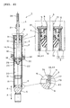
- In the following, the present invention is explained in greater detail with respect to several embodiments thereof in conjunction with the accompanying drawings, wherein:
- FIG. 1
- shows the
embodiment 1 and is a vertical cross-sectional view of the shock absorber, - FIG. 2
- shows the
embodiment 2 and is a view equivalent toFIG. 1 , - FIG. 3
- shows the
embodiment 2 and is a partical enlarged view ofFIG. 2 , - FIG. 4
- shows the
embodiment 3 and is a view equivalent toFIG. 1 , - FIG. 5
- shows the
embodiment 4 and is a view equivalent toFIG. 1 , and - FIG. 6
- shows the
embodiment 4 and is a cross-sectional view taken along arrows VI-VI inFIG. 5 . -
- 1: shock absorber
- 2: cylinder tube
- 3: axial center
- 4: tube main body
- 13: free piston
- 14: hydraulic oil
- 15: oil chamber
- 16: gas chamber
- 18: piston
- 19: first oil chamber
- 20: second oil chamber
- 21: piston rod
- 22: base end
- 26: expansion side damping force generation section
- 30: compression side damping force generation section
- 38: cavity
- 39: opening
- 41: lid
- 44: flowable matter
- 45: elastic body
- 48: through hole
- 49: movable rod guide
- 56: piston rod
- 69: cavity
- 72: lid
- 74: space
- 76: inner tube main body
- 77: outer tube main body
- 83: opening
- A: expanding operation
- B: compressing operation
- Objects of the present teaching in relation to the shock absorber include damping impact force applied to the shock absorber more effectively, further improving a lifetime of the shock absorber, and maintaining excellent assembly performance of the shock absorber to a vehicle or the like by avoiding enlarging the shock absorber regardless of the fact that the shock absorber can effectively damp impact force as described above. A best mode for carrying out the present invention for achieving these objects is as described below.
- The shock absorber includes: a cylinder tube; a piston fitted slidably in an axial direction in the cylinder tube defining an inside of the cylinder tube into a first and a second oil chambers; a piston rod extending from the piston to an outside of the cylinder tube; and a damping force generation section capable of generating damping force by making hydraulic oil flow between the first and the second oil chambers. A cavity is formed in a member of at least either one of the cylinder tube and the piston rod, and a flowable matter having a rheological characteristic is sealed in the cavity.
- In order to describe the present teaching in more detail, an
embodiment 1 will be described hereinafter with reference to the attachedFIG. 1 . - In
FIG. 1 , areference numeral 1 denotes a hydraulic shock absorber. Theshock absorber 1 is applied to a suspension system, a steering damper, and the like of a vehicle such as an automobile and a motorcycle. - The
shock absorber 1 is provided with thecylinder tube 2. Thecylinder tube 2 is provided with a tubemain body 4 positioned on anaxial center 3 of thecylinder tube 2 and extending in the axial direction, ahead cover 6 fixed on oneend 5 so as to close an opening of theend 5 in the axial direction of the tubemain body 4, a fixingrod guide 9 fixed on theother end 7 so as to close an opening of theend 7 of the tubemain body 4 and having a throughhole 8 formed on theaxial center 3, and abump stopper 10 attached to the fixingrod guide 9 and projecting toward the inside of the tubemain body 4. - A
free piston 13 is provided in thecylinder tube 2 and fitted slidably in the axial direction. Thefree piston 13 defines an inside of thecylinder tube 2 into an oil chamber 15 in whichhydraulic oil 14 is filled and agas chamber 16 in which high-pressure nitrogen gas is filled. In addition, thepiston 18 is provided to be fitted in the oil chamber 15 of thecylinder tube 2 slidably in the axial direction. Thepiston 18 defines the oil chamber 15 into thefirst oil chamber 19 and thesecond oil chamber 20. - The
piston rod 21 positioned on theaxial center 3, extending from thepiston 18, passing through the throughhole 8 of the fixingrod guide 9, and reaching an outside of thecylinder tube 2 is provided. Abase end 22 of thepiston rod 21 passes through thepiston 18, and thepiston 18 and thebase end 22 are fixed on each other by afastener 23. - The expansion side damping
force generation section 26 is provided, which generates damping force by making thehydraulic oil 14 flow from thefirst oil chamber 19 to thesecond oil chamber 20 when theshock absorber 1 performs an expanding operation A. The expansion side dampingforce generation section 26 is provided with an expansionside oil passage 27 formed in thepiston 18 so as to connect thefirst oil chamber 19 and thesecond oil chamber 20 and an expansionside damping valve 28 as a leaf valve for separating the expansionside oil passage 27 from a side of thesecond oil chamber 20 elastically in an openable and closable manner. - On the other hand, the compression side damping
force generation section 30 is provided, which generates damping force by making thehydraulic oil 14 flow from thesecond oil chamber 20 to thefirst oil chamber 19 when theshock absorber 1 performs a compressing operation B. The compression side dampingforce generation section 30 is provided with a compressionside oil passage 31 formed in thepiston 18 so as to connect thefirst oil chamber 19 and thesecond oil chamber 20 and a compressionside damping valve 32 as a leaf valve for separating the compressionside oil passage 31 from a side of thefirst oil chamber 19 elastically in an openable and closable manner. - An
external thread 35 is formed on an outer circumference of the extended end of thepiston rod 21 of thecylinder tube 2, and the extended end of thepiston rod 21 is supported on a side of the vehicle body. On the other hand, thehead cover 6 of thecylinder tube 2 is connected to a side of a wheel. Asuspension spring 34 for biasing thecylinder tube 2 in order to make theshock absorber 1 perform the expanding operation A is provided. - The
cavity 38 having a bottom is formed in a member of thepiston rod 21 in theshock absorber 1 having a constitution described above. Thecavity 38 is formed on theaxial center 3 of thepiston rod 21 and has a circular cross-section. A bottom on a side of one end of thecavity 38 is positioned at thebase end 22 of thepiston rod 21, and the other end of thecavity 38 is the opening 39 opened from an end surface of the extended end of thepiston rod 21 to the external force. - An internal thread 40 is formed on an inner circumference of the opening 39. The opening 39 is closed openably by a
lid 41 in a shape of a bolt screwed into internal thread 40. In addition, aseal 42 is interposed between the end surface of the extended end of thepiston rod 21 and thelid 41. - The
flowable matter 44 is fillingly sealed in thecavity 38. When thelid 41 is twistedly turned to open the opening 39, theflowable matter 44 can be removed or filled in relation to thecavity 38 via the opening 39. In addition, anelastic body 45 made of rubber is removably fitted in the opening 39. Theelastic body 45 is compressed elastically by screwing thelid 41. In addition, theflowable matter 44 enclosed in thecavity 38 is pressurized by theelastic body 45. - A substance having a rheological characteristic is used as the
flowable matter 44. Rheology is "the study of the deformation and flow of a material." Familiar liquid such as water and alcohol is subsequently understood as Newtonian fluid having a characteristic in which shear rate and shear stress are proportional to each other. On the other hand, the rheological characteristic refers to a characteristic of non-Newtonian fluid, in which no simple proportional relation is seen between shear rate and shear stress in a flow of matter having flowability in a broad sense including fine particles (including grains) and the like of inorganic matters such as a plastic solid matter and sand. - More particularly major substances which can be the
flowable matter 44 having the rheological characteristic are as follows. - The major substances include granular fluid classified on the basis of a nonlinear relation between shear rate and shear stress (sand and the like), dilatant fluid (a mixture of starch as a high viscosity material and water, a mixture of sand and water in an appropriate combination, and the like), pseudoplastic fluid (suspension or emulsion such as a solution or a melt of a high molecular material, starch paste, and cellulose ester and the like), and Bingham fluid (clay slurry, asphalt, paint, grease, and the like).
- In addition, the major substances also include thixotropy fluid and rheopexy fluid (gypsum suspension and bentonite suspension, high-temperature bentonite grease of a non-soap type) having time hysteresis concerning the nonlinear relation between shear rate and shear stress, and visco-elastic fluid showing an elastic behavior in addition to a viscous behavior in relation to a shear strain (a concentrated solution and a melt of a polymer), and the like.
- In the embodiment, sand as granular fluid is solely used as the
flowable matter 44. - When the vehicle is running, impact force may be applied from an outside in the axial direction to the
shock absorber 1, and therefore theshock absorber 1 may perform the expanding operation A in the direction of the bias of thesuspension spring 34. In this case, thehydraulic oil 14 in thefirst oil chamber 19 starts to flow toward thesecond oil chamber 20, passing through the expansionside oil passage 27 in the expansion side dampingforce generation section 26. Accordingly, the expansionside damping valve 28 causes elastic deformation and opens the valve due to oil pressure of thehydraulic oil 14 in thefirst oil chamber 19, which is larger than the elastic bias of the expansionside damping valve 28. As a result, thehydraulic oil 14 flows in the expansionside oil passage 27 slightly opened. Consequently, damping force is generated, and the impact force is damped. - On the other hand, the
shock absorber 1 may perform the compressing operation B in resistance to the bias of thesuspension spring 34 by the impact force. In this case, thehydraulic oil 14 in thesecond oil chamber 20 starts to flow toward thefirst oil chamber 19, passing through the compressionside oil passage 31 in the compression side dampingforce generation section 30. Accordingly, the compressionside damping valve 32 causes elastic deformation and opens the valve due to oil pressure of thehydraulic oil 14 in thesecond oil chamber 20, which is larger than the elastic bias of the compressionside damping valve 32. As a result, thehydraulic oil 14 flows in the compressionside oil passage 31 slightly opened. Consequently, damping force is generated, and the impact force is damped. - After this, the
shock absorber 1 performs the expanding operation A and the compressing operation B repeatedly. As a result, the impact force is damped. As theshock absorber 1 performs the expanding operation A and the compressing operation B, thepiston rod 21 moves in to or out of the oil chamber 15. On this occasion, since the volume of thehydraulic oil 14 of an incompressible type in the oil chamber 15 is constant, thefree piston 13 slides in the axial direction as much as the volume of thepiston rod 21 moving in to or out of the oil chamber 15 as described above. As a result, gas in thegas chamber 16 is expanded and compressed. Consequently, thepiston rod 21 can move in to or out of the oil chamber 15. - In addition, when impact force is applied to the
shock absorber 1, vibration of a high frequency and a micro amplitude is generated in the axial direction of theshock absorber 1. This vibration is suppressed by theflowable matter 44. Specifically, "deformation resistance" (viscous resistance, frictional resistance, and the like) is generated in theflowable matter 44 by vibration generated in theshock absorber 1, and further "deformation resistance" (see the above) of theflowable matter 44 is also generated in relation to an inner wall surface of thecavity 38. Consequently, the vibration is suppressed by generation of the "deformation resistance" of theflowable matter 44. Moreover, theflowable matter 44 can efficiently suppress vibration in a wider frequency range in comparison with the dynamic damper according to the conventional art. Consequently, the vibration is suppressed more surely. - In other words, according to the
shock absorber 1, impact force applied to theshock absorber 1 is damped by the expansion side dampingforce generation section 26 and the compression side dampingforce generation section 30, and vibration of a high frequency in a wide range and a micro amplitude generated in theshock absorber 1 by the impact force is more surely suppressed by theflowable matter 44. Therefore, the impact force is damped more effectively. As a result, ride comfort and quietness of the vehicle are improved. - Further, in general, the
flowable matter 44 is not easily deteriorated over time in comparison with the elastic body made of rubber in the dynamic damper according to the conventional art. Consequently, it is suppressed that a vibration suppression characteristic of theflowable matter 44 is deteriorated at an early stage. As a result, improvement of a lifetime of theshock absorber 1 is achieved. - Moreover, the
flowable matter 44 is sealed in thecavity 38 formed in the member of thepiston rod 21. In other words, theflowable matter 44 is provided by utilizing an inside of the member of thepiston rod 21. Therefore, it can be prevented that theshock absorber 1 is enlarged by the fact that theflowable matter 44 is provided. As a result, excellent assembly performance of theshock absorber 1 in relation to a vehicle or the like can be maintained by avoiding enlarging theshock absorber 1 regardless of the fact that theshock absorber 1 can effectively damp impact force as described above. - In addition, as described above, the
cavity 38 is formed in the member of thepiston rod 21, and the opening 39 which makes it possible to remove or fill theflowable matter 44 to thecavity 38 is formed at the extended end of thepiston rod 21. - Consequently, it is possible to remove or fill the
flowable matter 44 in relation to thecavity 38 from the opening 39 outside thecylinder tube 2. As a result, it is possible to change or adjust a type or an amount of theflowable matter 44 easily and conveniently without disassembling theshock absorber 1. - In addition, the opening 39 is formed at the extended end of the
piston rod 21. Therefore, when a seal is applied a case that the opening 39 is closed by thelid 41, it is not necessary to take thehydraulic oil 14 into consideration. It is only necessary to consider a seal between a side of atmospheric air and a side in thecavity 38. Consequently, theshock absorber 1 can be easily formed. Further, because a leak does not occur respectively between thehydraulic oil 14 and theflowable matter 44 in thecavity 38, reliability of the seal is enhanced. - Further in addition, as described above, the
flowable matter 44 sealed in thecavity 38 is pressurized. - Consequently, in particular, when the
flowable matter 44 is granular fluid, cohesion of each grain in the granular fluid is increased. Consequently, "deformation resistance" in theflowable matter 44 generated by the impact force is more frequently generated, and vibration generated in theshock absorber 1 by the impact force is suppressed more effectively. - Moreover, as described above, the
flowable matter 44 is granular fluid. - Typically, the granular fluid is sand. Further, the granular fluid can be easily handled, for example, when filled in the
cavity 38. In addition, a desired characteristic can be obtained relatively easily. Consequently, as theflowable matter 44 is the granular fluid, theshock absorber 1 can be easily formed. - As described above, sand as granular fluid is solely used as the
flowable matter 44. However, another constitution is possible as described below. - The
flowable matter 44 includes at least either substance of granular fluid and liquid having a small absolute specific gravity and granular fluid having an absolute specific gravity larger than that of the preceding substance. - In this constitution, when the
flowable matter 44 vibrates with theshock absorber 1 due to the impact force, the "deformation resistance" in theflowable matter 44 is further more frequently generated because of difference in inertial force caused by difference in the absolute specific gravity between the substances. As a result, vibration generated in theshock absorber 1 by the impact force is suppressed further more effectively. - Further in addition, the
flowable matter 44 can include granular fluid, and the granular fluid can be made by mixing grains having different grain diameters. - In this constitution, a grain having a small grain diameter enters a space produced between grains having a large grain diameter. Therefore, a contact area between these grains and a contact area between an inner surface of the
cavity 38 and theflowable matter 44 become larger. Consequently, the "deformation resistance" in theflowable matter 44 generated by the impact force is further more frequently generated, and vibration generated in theshock absorber 1 by the impact force is suppressed further more effectively. - Moreover, when the
flowable matter 44 vibrates with theshock absorber 1 due to the impact force, the "deformation resistance" in theflowable matter 44 is further more frequently generated because of difference in inertial force caused by difference between the grain diameters of the grains. As a result, vibration generated in theshock absorber 1 by the impact force is suppressed further more effectively. - Further, the
flowable matter 44 may include granular fluid, and surface treatment may be performed in order to adjust a coefficient of friction of a surface of each grain constituting the granular fluid. - In this case, the surface treatment is made to cause the surface of the grain to be rough in a grinding process by shot peening. In addition, the surface of the grain is coated with a resin material or an inorganic material. For instance, a surface of sand as a core is coated with a ceramics layer by vapor deposition and sputtering.
- In this constitution, a coefficient of friction of each grain in the granular fluid is set to a desired value. Accordingly, an amount of the "deformation resistance" in the
flowable matter 44 generated by the impact force can be made to be appropriate. In addition, if rigidity of a surface of each grain is enhanced by the surface treatment, deterioration over time of theflowable matter 44 can be prevented, and improvement of a lifetime is achieved. - Moreover, adsorptive power may be generated respectively between components of the
flowable matter 44, or adsorptive power may be generated respectively between theflowable matter 44 and an inner surface of thecavities - In this case, specifically, the tube
main body 4 and of thecylinder tube 2 and thepiston rod 21 is made of steel as a ferromagnetic material or the like. On the other hand, theflowable matter 44 is magnetized ferrite powder or the like. - In this constitution, because adsorptive power is generated respectively between components of the
flowable matter 44 and between theflowable matter 44 and an inner surface of thecavity 38, each friction force is increased. Consequently, an amount of "deformation resistance" in theflowable matter 44 generated by the impact force can be made to be larger. - In addition, when the
shock absorber 1 is vibrated, a state of each adsorption due to the adsorptive power and a state of separation in which the state of the adsorption is released by the vibration are repeated. Accordingly, abrupt internal agitation is generated in theflowable matter 44. Consequently, the "deformation resistance" in theflowable matter 44 is further more frequently generated. As a result, vibration generated in theshock absorber 1 by the impact force is suppressed further more effectively. - The description above is based on the example shown in the drawing. However, the
shock absorber 1 can be applied to an industrial machine and the like. Further, the expansion side dampingforce generation section 26 and the compression side dampingforce generation section 30 may be provided outside thecylinder tube 2 or may be formed in a material of the cylinder tube 2 (inside the material by increasing wall thickness). Still further, theelastic body 45 may not be provided, and theflowable matter 44 may be pressurized by some means after the opening 39 is closed by thelid 41. - In addition, a rheological flow characteristic can be effectively utilized in order to generate damping force having a characteristic not obtained solely by adjusting viscosity of Newtonian fluid depending on nonlinearity of viscosity, time irreversibility, and the like.
-
FIGs. 2 to 6 show embodiments 2 to 4. These embodiments have many in common with theembodiment 1 in relation to a constitution and an operation effect. Therefore, common reference numerals will be given to the drawings, the descriptions will not be repeated concerning things in common, and different points will be mainly described. In addition, a constitution of each part in these embodiments may be variously combined in accordance with an object and an operation effect of the present teaching. - In order to describe the present teaching in more detail, an
embodiment 2 will be described hereinafter with reference toFIGs. 2 and3 . - In
FIGs. 2 and3 , theshock absorber 1 in theembodiment 2 is of a so-called through rod (double rod) type. Areas under oil pressure of thehydraulic oil 14 on surfaces in the axial direction of thepiston 18 in theshock absorber 1 have generally the same dimensions. - Specifically, a
movable rod guide 49 through which a throughhole 48 is formed on theaxial center 3 is provided in place of thefree piston 13 of theembodiment 1. Themovable rod guide 49 is fitted in the tubemain body 4 of thecylinder tube 2 slidably in the axial direction. Further, ahousing chamber 53 passing through aconnection hole 52 formed in thehead cover 6 and connected to the atmosphere is formed in place of thegas chamber 16 of theembodiment 1. Thehousing chamber 53 is formed with oneend 5 of the tubemain body 4 and thehead cover 6. Aspring 54 elastically pushing themovable rod guide 49 toward a side of the oil chamber 15 is housed in thehousing chamber 53. A prescribed amount of pressure is constantly applied to thehydraulic oil 14 in the oil chamber 15 by a bias of thespring 54. - A
slider 55 in a shape of a cylinder in which a through hole is formed on theaxial center 3 is interposed between themovable rod guide 49 and thespring 54. Theslider 55 is fitted slidably in the axial direction without any rattle in the tubemain body 4. One end surface (an upper end surface) in the axial direction of theslider 55 is formed to be orthogonal to theaxial center 3 and is facingly in contact with one end surface (a lower end surface) in the axial direction of themovable rod guide 49. - One end surface (an upper end surface) in the axial direction of the
spring 54 pressed on an other end surface (a lower end surface) of theslider 55 in a free state of thespring 54 may be somewhat inclined in relation to an orthogonal surface concerning the axial center. Even so, it is prevented that theslider 55 starts to incline in relation to theaxial center 3 under the influence of the bias of thespring 54. Consequently, it is also prevented that themovable rod guide 49 facingly in contact with the one end surface of theslider 55 starts to incline in relation to theaxial center 3 under the influence of the bias of thespring 54. As a result, a smooth slide of themovable rod guide 49 to the tubemain body 4 is secured. - The
other piston rod 56 positioned on theaxial center 3, extending from thepiston 18, passing through the throughhole 48, and reaching thehousing chamber 53 is provided. Thepiston rod 56 is provided with thebase end 22 of thepiston rod 21 fixed on thepiston 18 and a rodmain body 58 fixed on a projectedend 22a of thebase end 22 projecting from thepiston 18 to thesecond oil chamber 20 by afastener 57. In other words, thebase end 22 is shared by thepiston rods piston rods - As described above, the
piston rods piston 18. Accordingly, as described above, the areas under oil pressure on the surfaces in the axial direction of thepiston 18 have generally the same dimensions. As a result, it is suppressed that thepiston 18 receives pressurizing reaction force from thespring 54. - A
fitting hole 59 having a bottom is formed at a base end of the rodmain body 58 on theaxial center 3. Thefastener 57 is provided with anexternal thread 60 formed on an outer circumference of the projectedend 22a of thebase end 22 and an internal thread 61 formed on an inner circumference of thefitting hole 59. Thefitting hole 59 of the rodmain body 58 is fitted with the projectedend 22a of thebase end 22, and theexternal thread 60 and the internal thread 61 are screwed. Consequently, a bottom section in thefitting hole 59 is a space enclosed by the projectedend 22a of thebase end 22. - The
cavity 38 passes through the projectedend 22a of thebase end 22, further passes through an other opening 64 formed in the projectedend 22a, and is opened to a bottom in thefitting hole 59. An internal thread 65 is formed on an inner circumference of the other opening 64. The other opening 64 is closed openably by alid 66 in a shape of a bolt screwed with the internal thread 65. In addition, aseal 67 is interposed between the inner circumference of the opening 64 and thelid 66. - An
other cavity 69 having a bottom is formed in a member of the rodmain body 58 in theother piston rod 56. Theother cavity 69 is formed on theaxial center 3 of thepiston rod 56. Theother cavity 69 has a circular cross-section, and its diameter is larger than that of thecavity 38. In addition, an opening 70 which opens theother cavity 69 to thehousing chamber 53 is formed at an extended end of theother piston rod 56. - An internal thread 71 is formed on an inner circumference of the opening 70. The opening 70 is closed openably by a
lid 72 in a shape of a bolt screwed with the internal thread 71. In addition, a seal (not shown) is provided between the inner circumference of the opening 70 and thelid 72. Sand as granular fluid belonging to theflowable matter 44 is fillingly sealed in thecavity 69. - When the
shock absorber 1 is in a static state, theflowable matter 44 is incompletely filled in thecavity 38 of thepiston rod 21 so as to maintain thespace 74 at an upper end of thecavity 38. Even if thecavity 38 is fully filled with theflowable matter 44 at a time when theflowable matter 44 is injected, thecavity 38 may be incompletely filled with theflowable matter 44 as described above after a certain period of time elapses in a case that theflowable matter 44 is granular fluid. Specifically, even if theflowable matter 44 is fully enclosed in thecavity 38, each grain of the granular fluid sinks as time passes because of its own weight. Accordingly, since apparent specific gravity of the granular fluid is gradually increased, thespace 74 may be generated at the upper end of thecavity 38. - In the constitution described above, when the
flowable matter 44 vibrates with theshock absorber 1 due to the impact force, fluidization of theflowable matter 44 in thecavity 69 is accelerated by thespace 74 provided as described above. As a result, the "deformation resistance" in theflowable matter 44 generated by the impact force is more frequently generated, and vibration generated in theshock absorber 1 by the impact force is suppressed more effectively. - In order to describe the present teaching in detail, an
embodiment 3 will be described hereinafter with reference toFIG. 4 . - In
FIG. 4 , the tubemain body 4 of thecylinder tube 2 is constituted with a multiple tube made with an inner and an outer tubemain bodies head cover 6 has asmall diameter section 79 and alarge diameter section 80, and the small and thelarge diameter sections main body 76 is externally fitted and fixed with thesmall diameter section 79, and an end of the outer tubemain body 77 is externally fitted with thelarge diameter section 80. On the other hand, aspacer 81 in a shape of a ring is interposed between the inner and the outer tubemain bodies other end 7 of the tubemain body 4. - Further, the
cavity 38 in a shape of a cylinder is formed between the inner and the outer tubemain bodies flowable matter 44 is sealed in thecavity 38. An effect by thecavity 38 and theflowable matter 44 is the same as that of the preceding embodiment. - In order to describe the present teaching in detail, an
embodiment 4 will be described hereinafter with reference toFIGs. 5 and6 . - In
FIGs. 5 and6 , the tubemain body 4 of thecylinder tube 2 is formed by extrusion. A plurality of the cavities 38 (six cavities) passing through a member of the tubemain body 4 in the axial direction are formed. Cross-sections of thecavities 38 forms a circular arc with theaxial center 3 at the center, and each cross-section is in the same shape and of the same size and disposed at a regular pitch in the direction of a circumference around theaxial center 3. Astopper 84 closing anopening 83 of each end in the longitudinal direction of eachcavity 38 is provided. - A first embodiment of the present teaching provides a hydraulic shock absorber including: a
cylinder tube 2; apiston 18 fitted slidably in an axial direction in thecylinder tube 2 for defining an inside of thecylinder tube 2 into a first and asecond oil chambers piston rod 21 extending from thepiston 18 to an outside of thecylinder tube 2; and dampingforce generation sections hydraulic oil 14 flow between the first and thesecond oil chambers cylinder tube 2, thepiston rod 21, and apiston rod 56, andflowable matter 44 having a rheological characteristic is sealed in thecavities - According to a second embodiment of the present teaching, in addition to the first embodiment of the present teaching, the
cavities piston rod 21, and an opening 39 which makes it possible to remove or fill theflowable matter 44 to thecavities piston rod 21. - According to a third embodiment of the present teaching, in addition to the first or second embodiment of the present teaching, the
flowable matter 44 sealed in thecavities - According to a fourth embodiment of the present teaching, in addition to the first to third embodiments of the present teaching, the
flowable matter 44 is granular fluid. - According to a fifth embodiment of the present teaching, in addition to the first to fourth embodiments of the present teaching, the
flowable matter 44 includes at least either substance of granular fluid and liquid having a small absolute specific gravity and granular fluid having an absolute specific gravity larger than that of the preceding substance. - According to a sixth embodiment of the present teaching, in addition to the first to fifth embodiments of the present teaching, the
flowable matter 44 includes granular fluid, and the granular fluid is made by mixing grains having different grain diameters. - According to a seventh embodiment of the present teaching, in addition to the first to sixth embodiments of the present teaching, the
flowable matter 44 includes granular fluid, and surface treatment is performed in order to adjust a coefficient of friction of a surface of each grain constituting the granular fluid. - According to an eighth embodiment of the present teaching, in addition to the first to seventh embodiments of the present teaching, adsorptive power is generated respectively between components of the
flowable matter 44, or adsorptive power is generated respectively between theflowable matter 44 and an inner surface of thecavities - According to a ninth embodiment of the present teaching, in addition to the first to eighth embodiments of the present teaching, the
flowable matter 44 is incompletely filled in thecavities space 74 at an upper end of thecavities - A technical scope of the present teaching is not limited to an embodiment described below or to a content of a drawing regardless of reference numerals used with a description above.
- An effect of the present teaching will be described hereinafter.
- According to a first embodiment of the present teaching, there is provided the hydraulic shock absorber including: a cylinder tube; a piston fitted slidably in an axial direction in the cylinder tube and defining an inside of the cylinder tube into a first and a second oil chambers; a piston rod extending from the piston to an outside of the cylinder tube; for a damping force generation section capable of generating damping force by making hydraulic oil flow between the first and the second oil chambers; in which a cavity is formed in a member of at least either one of the cylinder tube and the piston rod, and flowable matter having a rheological characteristic is enclosed in the cavity.
- Consequently, when impact force is applied from an outside to the shock absorber, the shock absorber is expanded or compressed. As a result, damping force is generated by the fact that the hydraulic oil flows in the damping force generation section, and the impact force is damped.
- In addition, when impact force is applied to the shock absorber, vibration of a high frequency and a micro amplitude is generated in the shock absorber. This vibration is suppressed by the flowable matter. Specifically, "deformation resistance" (viscous resistance, frictional resistance, and the like) is generated in the flowable matter by vibration generated in the shock absorber, and further "deformation resistance" (see above) of the flowable matter is also generated to an inner surface of the cavity. Consequently, the vibration is suppressed by generation of the "deformation resistance" of the flowable matter. Moreover, the flowable matter can efficiently suppress vibration in a wider frequency range in comparison with the dynamic damper according to the conventional art. As a result, the vibration is suppressed more surely.
- Specifically, according to the shock absorber, impact force applied to the shock absorber is damped by the damping force generation section, and vibration of a high frequency in a wide range and a micro amplitude generated in the shock absorber by the impact force is more surely suppressed by the flowable matter. As a result, the impact force is damped more effectively.
- Further, in general, the flowable matter is not easily deteriorated over time in comparison with the elastic body made of rubber in the dynamic damper according to the conventional art. Consequently, it is suppressed that a vibration suppression characteristic of the flowable matter is deteriorated at an early stage. As a result, improvement of a lifetime of the shock absorber is achieved.
- Moreover, the flowable matter is sealed in the cavity formed in the member of the cylinder tube and the piston rod. In other words, the flowable matter is provided by utilizing an inside of the member of the cylinder tube and the piston rod. Therefore, it can be prevented that the shock absorber is enlarged by the fact that the flowable matter is provided. As a result, excellent assembly performance of the shock absorber to a vehicle or the like can be maintained by avoiding enlarging the shock absorber regardless of the fact that the shock absorber can effectively damp impact force as described above.
- According to the second embodiment of the present teaching, the cavity is formed in a member of the piston rod, and the opening which makes it possible to remove or fill the flowable matter to the cavity is formed at an extended end of the piston rod.
- Consequently, it is possible to remove or fill the flowable matter to the cavity from the opening outside the cylinder tube. As a result, it is possible to change or adjust a type or an amount of the flowable matter easily and conveniently without disassembling the shock absorber.
- Further, the opening is formed at the extended end of the piston rod. Therefore, when a seal is applied in order to close the opening, it is not necessary to take the hydraulic oil into consideration. It is only necessary to consider a seal between a side of atmospheric air and a side in the cavity. As a result, the shock absorber can be easily formed. In addition, because a leak does not occur respectively between the hydraulic oil and the flowable matter in the cavity, reliability of the seal is enhanced.
- According to the third embodiment of the present teaching, the flowable matter sealed in the cavity is pressurized.
- Consequently, in particular, when the flowable matter is granular fluid, cohesion of each grain in the granular fluid is increased. As a result, the "deformation resistance" in the flowable matter generated by the impact force is more frequently generated, and vibration generated in the shock absorber by the impact force is suppressed more effectively.
- According to the fourth embodiment of the present teaching, the flowable matter is granular fluid.
- Typically, the granular fluid is sand. Further, the granular fluid can be easily handled, for example, when filled in the cavity. In addition, a desired characteristic can be obtained relatively easily. As a result, since the flowable matter is the granular fluid, the shock absorber can be easily formed.
- According to the fifth embodiment of the present teaching, the flowable matter includes at least either substance of granular fluid and liquid having a small absolute specific gravity and granular fluid having an absolute specific gravity larger than that of the preceding substance.
- Consequently, when the flowable matter vibrates with the shock absorber due to the impact force, the "deformation resistance" in the flowable matter is further more frequently generated because of difference in inertial force caused by difference in the absolute specific gravity between the substances. As a result, vibration generated in the shock absorber by the impact force is suppressed further more effectively.
- According to the sixth embodiment of the present teaching, the flowable matter includes granular fluid, and the granular fluid is made by mixing grains having different grain diameters.
- Consequently, a grain having a small grain diameter enters a space generated between grains having a large grain diameter. Therefore, a contact area between these grains and a contact area between an inner surface of the cavity and the flowable matter become larger. As a result, "deformation resistance" in the flowable matter generated by the impact force is further more frequently generated, and vibration generated in the shock absorber by the impact force is suppressed further more effectively.
- In addition, when the flowable matter vibrates with the shock absorber due to the impact force, the "deformation resistance" in the flowable matter is further more frequently generated because of difference in inertial force caused by difference between the grain diameters of the grains. As a result, vibration generated in the shock absorber by the impact force is suppressed further more effectively.
- According to the seventh embodiment of the present teaching, the flowable matter includes granular fluid, and surface treatment is performed in order to adjust a coefficient of friction of a surface of each grain constituting the granular fluid.
- Consequently, an amount of the "deformation resistance" in the flowable matter generated by the impact force can be made to be appropriate. In addition, if rigidity of a surface of each grain is enhanced by the surface treatment, deterioration over time of the flowable matter can be prevented, and improvement of a lifetime is achieved.
- According to the eighth embodiment of the present teaching, adsorptive power is generated respectively between components of the flowable matter, or adsorptive power is generated respectively between the flowable matter and an inner surface of the cavity.
- Consequently, because adsorptive power is generated respectively between components of the flowable matter and between the flowable matter and an inner surface of the cavity, each friction force is increased. As a result, an amount of the "deformation resistance" in the flowable matter generated by the impact force can be made to be larger.
- In addition, when the shock absorber is vibrated, a state of each adsorption due to the adsorptive power and a state of separation in which the state of the adsorption is released by the vibration are repeated. Accordingly, abrupt internal agitation is generated in the flowable matter. Consequently, the "deformation resistance" in the flowable matter is further more frequently generated. As a result, vibration generated in the shock absorber by the impact force is suppressed further more effectively.
- According to the ninth embodiment of the present teaching, the flowable matter is incompletely filled in the cavity in order to maintain a space at an upper end of the cavity.
- Consequently, when the flowable matter vibrates with the shock absorber due to the impact force, fluidization of the flowable matter in the cavity is promoted by the space provided as described above. As a result, "deformation resistance" in the flowable matter generated by the impact force is more frequently generated, and vibration generated in the shock absorber by the impact force is suppressed more effectively.
- The description further discloses, in order to damp impact force applied to a shock absorber more effectively, to further improve a lifetime of the shock absorber, and to maintain excellent assembly performance of the shock absorber to a vehicle or the like by avoiding enlarging the shock absorber, an embodiment of a
shock absorber 1 provided with acylinder tube 2, apiston 18 fitted slidably in an axial direction in thecylinder tube 2 for defining an inside of thecylinder tube 2 into a first and asecond oil chambers piston rod 21 extending from thepiston 18 to an outside of thecylinder tube 2, and dampingforce generation sections hydraulic oil 14 flow between the first and thesecond oil chambers Cavities cylinder tube 2 and thepiston rod cavities - Further, according to a preferred first aspect, there is provided a hydraulic shock absorber, comprising: a cylinder tube; a piston fitted slidably in an axial direction in the cylinder tube for defining an inside of the cylinder tube into a first and a second oil chambers; a piston rod extending from the piston to an outside of the cylinder tube; and a damping force generation section capable of generating damping force by making hydraulic oil flow between the first and the second oil chambers; wherein a cavity is formed in a member of at least either one of the cylinder tube and the piston rod, and flowable matter having a rheological characteristic is sealed in the cavity.
- Further, according to a preferred second aspect, the cavity is formed in a member of the piston rod, and an opening which makes it possible to remove or fill the flowable matter to the cavity is formed at an extended end of the piston rod.
- Further, according to a preferred third aspect, the flowable matter sealed in the cavity is pressurized.
- Further, according to a preferred fourth aspect, the flowable matter is granular fluid.
- Further, according to a preferred fifth aspect, the flowable matter includes at least either substance of granular fluid and liquid having a small absolute specific gravity and granular fluid having an absolute specific gravity larger than that of the preceding substance.
- Further, according to a preferred sixth aspect, the flowable matter includes granular fluid, and the granular fluid is made by mixing grains having different grain diameters.
- Further, according to a preferred seventh aspect, the flowable matter includes granular fluid, and surface treatment is performed in order to adjust a coefficient of friction of a surface of each grain constituting the granular fluid.
- Further, according to a preferred eighth aspect, adsorptive power is generated respectively between components of the flowable matter, or adsorptive power is generated respectively between the flowable matter and an inner surface of the cavity.
- Further, according to a preferred ninth aspect, the flowable matter is incompletely filled in the cavity in order to maintain a space at an upper end of the cavity.
Claims (9)
- Hydraulic shock absorber (1), comprising:a cylinder tube (2);a piston (18) fitted slidably in an axial direction in the cylinder tube (2) for defining an inside of the cylinder tube (2) into first and second chambers (19,20);a piston rod (21,56) extending from the piston (18) to an outside of the cylinder tube (2); anda damping force generation section (26,30) capable of generating a damping force by making hydraulic liquid flow between the first and the second chambers (19,20);wherein at least one cavity (38,69) is formed in at least either one of the cylinder tube (2) and the piston rod (21,56), and wherein
flowable matter having a rheological characteristic is sealed in the at least one cavity (38,69). - Hydraulic shock absorber according to claim 1, wherein the cavity (38,69) is formed in the piston rod, and an opening which makes it possible to remove the flowable matter from the cavity and to fill the flowable matter into the cavity is formed at an extended end of the piston rod.
- Hydraulic shock absorber according to claim 1 or 2, wherein the flowable matter sealed in the cavity is pressurized.
- Hydraulic shock absorber according to claim 1 or 2, wherein the flowable matter is incompletely filled in the cavity in order to maintain a space at an upper end of the cavity.
- Hydraulic shock absorber according to one of the claims 1 to 4, wherein the flowable matter is granular fluid.
- Hydraulic shock absorber according to one of the claims 1 to 4, wherein the flowable matter includes at least either substance of granular fluid and liquid having a small absolute specific gravity, together with a granular fluid having an absolute specific gravity larger than that of the preceding substance.
- Hydraulic shock absorber according to one of the claims 1 to 4, wherein the flowable matter includes granular fluid, and the granular fluid is made by mixing grains having different grain diameters.
- Hydraulic shock absorber according to one of the claims 1 to 4, wherein the flowable matter includes granular fluid, and surface treatment is performed in order to adjust a coefficient of friction of a surface of each grain constituting the granular fluid.
- Hydraulic shock absorber according to one of the claims 1 to 8, wherein adsorptive power is generated respectively between components of the flowable matter, or adsorptive power is generated respectively between the flowable matter and an inner surface of the cavity.
Applications Claiming Priority (1)
| Application Number | Priority Date | Filing Date | Title |
|---|---|---|---|
| JP2006330033A JP2008144789A (en) | 2006-12-06 | 2006-12-06 | Hydraulic buffer |
Publications (3)
| Publication Number | Publication Date |
|---|---|
| EP1930620A2 true EP1930620A2 (en) | 2008-06-11 |
| EP1930620A3 EP1930620A3 (en) | 2011-05-25 |
| EP1930620B1 EP1930620B1 (en) | 2013-05-01 |
Family
ID=39079492
Family Applications (1)
| Application Number | Title | Priority Date | Filing Date |
|---|---|---|---|
| EP07023596.5A Not-in-force EP1930620B1 (en) | 2006-12-06 | 2007-12-05 | Hydraulic shock absorber |
Country Status (3)
| Country | Link |
|---|---|
| US (1) | US20080135362A1 (en) |
| EP (1) | EP1930620B1 (en) |
| JP (1) | JP2008144789A (en) |
Cited By (1)
| Publication number | Priority date | Publication date | Assignee | Title |
|---|---|---|---|---|
| CN110701239A (en) * | 2019-10-21 | 2020-01-17 | 重庆大学 | New vibration damping and buffering integrated device |
Families Citing this family (10)
| Publication number | Priority date | Publication date | Assignee | Title |
|---|---|---|---|---|
| KR101776323B1 (en) * | 2010-09-29 | 2017-09-07 | 히다치 오토모티브 시스템즈 가부시키가이샤 | Damper |
| JP5906118B2 (en) * | 2012-03-29 | 2016-04-20 | Kyb株式会社 | shock absorber |
| DE102015217750B4 (en) * | 2015-09-16 | 2021-08-05 | Zf Friedrichshafen Ag | Extension for a vibration damper |
| US20170284494A1 (en) * | 2016-04-02 | 2017-10-05 | Avery Jackson Kress | Non Newtonian Fluids As Ultra High Acceleration G-Force Dissipaters And Shock Absorbers |
| CN111139627A (en) * | 2020-03-09 | 2020-05-12 | 珠海格力电器股份有限公司 | Rolling type damping device and washing machine |
| CN111963627B (en) * | 2020-08-03 | 2024-10-11 | 珠海格力电器股份有限公司 | Combined vibration damper, compressor, pump and fan |
| CN112360914A (en) * | 2020-10-22 | 2021-02-12 | 同济大学 | Fluid-solid coupling inertial container |
| US12313045B2 (en) * | 2021-09-30 | 2025-05-27 | Moshun, LLC | Multi-shear thickening fluid enabled object movement control mechanism |
| CN113958649A (en) * | 2021-10-31 | 2022-01-21 | 成都九鼎科技(集团)有限公司 | Hydraulic buffer assembly of shock absorber and gradual change type stroke adjustment shock absorber |
| KR102485697B1 (en) * | 2021-11-17 | 2023-01-06 | 나승웅 | Chicken cutting machine |
Citations (1)
| Publication number | Priority date | Publication date | Assignee | Title |
|---|---|---|---|---|
| JP2003166579A (en) | 2001-11-29 | 2003-06-13 | Hitachi Unisia Automotive Ltd | Vehicle hydraulic shock absorber |
Family Cites Families (18)
| Publication number | Priority date | Publication date | Assignee | Title |
|---|---|---|---|---|
| GB1280301A (en) * | 1969-03-28 | 1972-07-05 | Ass Eng Ltd | Improvements relating to damping |
| US4011929A (en) * | 1975-05-02 | 1977-03-15 | General Electric Company | Dampening device using a silicone rubber |
| SU1017852A1 (en) * | 1981-09-23 | 1983-05-15 | Коммунарский горно-металлургический институт | Energy absorbing apparatus |
| FR2533506B1 (en) * | 1982-09-28 | 1987-06-26 | Ouest Cie | ANTI-VIBRATION ELASTIC SUPPORT |
| JPS61165037A (en) * | 1985-12-27 | 1986-07-25 | Sanwa Tekki Corp | Micro-vibration absorbing device |
| JPS644936U (en) * | 1987-06-29 | 1989-01-12 | ||
| US5161653A (en) * | 1989-04-18 | 1992-11-10 | Hare Sr Nicholas S | Electro-rheological shock absorber |
| US5027715A (en) * | 1990-02-12 | 1991-07-02 | Mid-West Conveyor Company, Inc. | Shock absorbing carrier |
| US5578238A (en) * | 1992-10-30 | 1996-11-26 | Lord Corporation | Magnetorheological materials utilizing surface-modified particles |
| US5900184A (en) * | 1995-10-18 | 1999-05-04 | Lord Corporation | Method and magnetorheological fluid formulations for increasing the output of a magnetorheological fluid device |
| US6065572A (en) * | 1995-11-13 | 2000-05-23 | The Lubrizol Corporation | Polymeric materials to self-regulate the level of polar activators in electrorheological fluids |
| DE19813578A1 (en) * | 1998-03-27 | 1999-09-30 | Ruediger Ufermann | Vibration damper controlled by electro-rheological fluid |
| US6474598B2 (en) * | 2000-05-24 | 2002-11-05 | Cartercopters, L.L.C. | Landing gear shock absorber with variable viscosity fluid |
| US6279702B1 (en) * | 2001-01-05 | 2001-08-28 | Mando Corporation | Shock absorber using a hydraulic fluid and a magnetorheological fluid |
| JP4204347B2 (en) * | 2003-02-21 | 2009-01-07 | 義男 鈴木 | Seismic isolation devices for building structures |
| JP2004353712A (en) * | 2003-05-27 | 2004-12-16 | Nsk Ltd | Fluid for shock absorber |
| JP2006307982A (en) * | 2005-04-28 | 2006-11-09 | Honda Motor Co Ltd | Variable damping force damper |
| DE102006062284A1 (en) * | 2006-12-22 | 2008-06-26 | Andritz Küsters GmbH & Co. KG | Roller with vibration damper and method for damping vibrations of a roller |
-
2006
- 2006-12-06 JP JP2006330033A patent/JP2008144789A/en active Pending
-
2007
- 2007-12-05 EP EP07023596.5A patent/EP1930620B1/en not_active Not-in-force
- 2007-12-06 US US11/951,931 patent/US20080135362A1/en not_active Abandoned
Patent Citations (1)
| Publication number | Priority date | Publication date | Assignee | Title |
|---|---|---|---|---|
| JP2003166579A (en) | 2001-11-29 | 2003-06-13 | Hitachi Unisia Automotive Ltd | Vehicle hydraulic shock absorber |
Cited By (2)
| Publication number | Priority date | Publication date | Assignee | Title |
|---|---|---|---|---|
| CN110701239A (en) * | 2019-10-21 | 2020-01-17 | 重庆大学 | New vibration damping and buffering integrated device |
| CN110701239B (en) * | 2019-10-21 | 2021-07-20 | 重庆大学 | Vibration and buffering integrated device |
Also Published As
| Publication number | Publication date |
|---|---|
| EP1930620B1 (en) | 2013-05-01 |
| JP2008144789A (en) | 2008-06-26 |
| EP1930620A3 (en) | 2011-05-25 |
| US20080135362A1 (en) | 2008-06-12 |
Similar Documents
| Publication | Publication Date | Title |
|---|---|---|
| EP1930620B1 (en) | Hydraulic shock absorber | |
| KR101506428B1 (en) | Sealing device and damper with sealing device | |
| US4576366A (en) | Antivibration elastic support | |
| JP5008667B2 (en) | Asymmetrical suction damping valve | |
| JP4638921B2 (en) | Damping force variable device | |
| JPH07505697A (en) | surface effect damper | |
| JP2011021648A (en) | Damper apparatus | |
| EP1826454A3 (en) | Vibration damper with selective damping force amplitude | |
| CN105917064A (en) | Systems and methods for piston assemblies | |
| CN101680505B (en) | Shock absorber | |
| CN1871451A (en) | Adjacent baffle design for shock absorber | |
| US20200086708A1 (en) | Bump Stop | |
| DE112014004204T5 (en) | Hydraulic shock absorbers of monotube type | |
| US10352391B2 (en) | Vibration damper with a traction stop | |
| JP6391512B2 (en) | Pressure shock absorber | |
| JP6973712B2 (en) | damper | |
| US7252031B2 (en) | Cylinder apparatus | |
| US20120193849A1 (en) | Suspension device for vehicles | |
| JP2004251413A (en) | Sealing device for reciprocation spindle | |
| CN207961392U (en) | Damper and engineering truck | |
| Morishita et al. | Basic damping property of a double-rod type damper utilizing an elastomer particle assemblage | |
| WO2005114001A3 (en) | Damping device with power-assisted deceleration and use thereof for the damping of the retractable steering column of a motor vehicle | |
| Novikov et al. | Method of calculating the adaptive damper of the pneumohydraulic spring for the suspension of a high-speed vehicle | |
| Hammad et al. | Modeling of Hydrogas Unit for Tracked Vehicle Suspension | |
| CN107076249A (en) | With the shock absorber for drawing backstop and pressure backstop |
Legal Events
| Date | Code | Title | Description |
|---|---|---|---|
| PUAI | Public reference made under article 153(3) epc to a published international application that has entered the european phase |
Free format text: ORIGINAL CODE: 0009012 |
|
| AK | Designated contracting states |
Kind code of ref document: A2 Designated state(s): AT BE BG CH CY CZ DE DK EE ES FI FR GB GR HU IE IS IT LI LT LU LV MC MT NL PL PT RO SE SI SK TR |
|
| AX | Request for extension of the european patent |
Extension state: AL BA HR MK RS |
|
| PUAL | Search report despatched |
Free format text: ORIGINAL CODE: 0009013 |
|
| AK | Designated contracting states |
Kind code of ref document: A3 Designated state(s): AT BE BG CH CY CZ DE DK EE ES FI FR GB GR HU IE IS IT LI LT LU LV MC MT NL PL PT RO SE SI SK TR |
|
| AX | Request for extension of the european patent |
Extension state: AL BA HR MK RS |
|
| RIC1 | Information provided on ipc code assigned before grant |
Ipc: F16F 9/06 20060101ALI20110421BHEP Ipc: F16F 7/01 20060101AFI20080221BHEP Ipc: F16F 9/00 20060101ALI20110421BHEP Ipc: F16F 7/10 20060101ALI20110421BHEP Ipc: F16F 9/36 20060101ALI20110421BHEP Ipc: F16F 9/32 20060101ALI20110421BHEP |
|
| 17P | Request for examination filed |
Effective date: 20110615 |
|
| AKX | Designation fees paid |
Designated state(s): AT BE BG CH CY CZ DE DK EE ES FI FR GB GR HU IE IS IT LI LT LU LV MC MT NL PL PT RO SE SI SK TR |
|
| GRAP | Despatch of communication of intention to grant a patent |
Free format text: ORIGINAL CODE: EPIDOSNIGR1 |
|
| RIC1 | Information provided on ipc code assigned before grant |
Ipc: F16F 9/36 20060101ALI20121112BHEP Ipc: F16F 7/01 20060101AFI20121112BHEP Ipc: F16F 9/53 20060101ALI20121112BHEP Ipc: F16F 9/00 20060101ALI20121112BHEP Ipc: F16F 9/32 20060101ALI20121112BHEP Ipc: F16F 7/10 20060101ALI20121112BHEP Ipc: F16F 9/06 20060101ALI20121112BHEP |
|
| GRAS | Grant fee paid |
Free format text: ORIGINAL CODE: EPIDOSNIGR3 |
|
| GRAA | (expected) grant |
Free format text: ORIGINAL CODE: 0009210 |
|
| AK | Designated contracting states |
Kind code of ref document: B1 Designated state(s): AT BE BG CH CY CZ DE DK EE ES FI FR GB GR HU IE IS IT LI LT LU LV MC MT NL PL PT RO SE SI SK TR |
|
| REG | Reference to a national code |
Ref country code: GB Ref legal event code: FG4D |
|
| REG | Reference to a national code |
Ref country code: CH Ref legal event code: EP Ref country code: AT Ref legal event code: REF Ref document number: 610139 Country of ref document: AT Kind code of ref document: T Effective date: 20130515 |
|
| REG | Reference to a national code |
Ref country code: IE Ref legal event code: FG4D |
|
| REG | Reference to a national code |
Ref country code: DE Ref legal event code: R096 Ref document number: 602007030126 Country of ref document: DE Effective date: 20130627 |
|
| REG | Reference to a national code |
Ref country code: AT Ref legal event code: MK05 Ref document number: 610139 Country of ref document: AT Kind code of ref document: T Effective date: 20130501 |
|
| REG | Reference to a national code |
Ref country code: NL Ref legal event code: VDEP Effective date: 20130501 |
|
| REG | Reference to a national code |
Ref country code: LT Ref legal event code: MG4D |
|
| PG25 | Lapsed in a contracting state [announced via postgrant information from national office to epo] |
Ref country code: AT Free format text: LAPSE BECAUSE OF FAILURE TO SUBMIT A TRANSLATION OF THE DESCRIPTION OR TO PAY THE FEE WITHIN THE PRESCRIBED TIME-LIMIT Effective date: 20130501 Ref country code: SI Free format text: LAPSE BECAUSE OF FAILURE TO SUBMIT A TRANSLATION OF THE DESCRIPTION OR TO PAY THE FEE WITHIN THE PRESCRIBED TIME-LIMIT Effective date: 20130501 Ref country code: ES Free format text: LAPSE BECAUSE OF FAILURE TO SUBMIT A TRANSLATION OF THE DESCRIPTION OR TO PAY THE FEE WITHIN THE PRESCRIBED TIME-LIMIT Effective date: 20130812 Ref country code: LT Free format text: LAPSE BECAUSE OF FAILURE TO SUBMIT A TRANSLATION OF THE DESCRIPTION OR TO PAY THE FEE WITHIN THE PRESCRIBED TIME-LIMIT Effective date: 20130501 Ref country code: PT Free format text: LAPSE BECAUSE OF FAILURE TO SUBMIT A TRANSLATION OF THE DESCRIPTION OR TO PAY THE FEE WITHIN THE PRESCRIBED TIME-LIMIT Effective date: 20130902 Ref country code: SE Free format text: LAPSE BECAUSE OF FAILURE TO SUBMIT A TRANSLATION OF THE DESCRIPTION OR TO PAY THE FEE WITHIN THE PRESCRIBED TIME-LIMIT Effective date: 20130501 Ref country code: FI Free format text: LAPSE BECAUSE OF FAILURE TO SUBMIT A TRANSLATION OF THE DESCRIPTION OR TO PAY THE FEE WITHIN THE PRESCRIBED TIME-LIMIT Effective date: 20130501 Ref country code: GR Free format text: LAPSE BECAUSE OF FAILURE TO SUBMIT A TRANSLATION OF THE DESCRIPTION OR TO PAY THE FEE WITHIN THE PRESCRIBED TIME-LIMIT Effective date: 20130802 Ref country code: IS Free format text: LAPSE BECAUSE OF FAILURE TO SUBMIT A TRANSLATION OF THE DESCRIPTION OR TO PAY THE FEE WITHIN THE PRESCRIBED TIME-LIMIT Effective date: 20130901 |
|
| PG25 | Lapsed in a contracting state [announced via postgrant information from national office to epo] |
Ref country code: PL Free format text: LAPSE BECAUSE OF FAILURE TO SUBMIT A TRANSLATION OF THE DESCRIPTION OR TO PAY THE FEE WITHIN THE PRESCRIBED TIME-LIMIT Effective date: 20130501 Ref country code: BG Free format text: LAPSE BECAUSE OF FAILURE TO SUBMIT A TRANSLATION OF THE DESCRIPTION OR TO PAY THE FEE WITHIN THE PRESCRIBED TIME-LIMIT Effective date: 20130801 Ref country code: CY Free format text: LAPSE BECAUSE OF FAILURE TO SUBMIT A TRANSLATION OF THE DESCRIPTION OR TO PAY THE FEE WITHIN THE PRESCRIBED TIME-LIMIT Effective date: 20130501 |
|
| PG25 | Lapsed in a contracting state [announced via postgrant information from national office to epo] |
Ref country code: LV Free format text: LAPSE BECAUSE OF FAILURE TO SUBMIT A TRANSLATION OF THE DESCRIPTION OR TO PAY THE FEE WITHIN THE PRESCRIBED TIME-LIMIT Effective date: 20130501 |
|
| PG25 | Lapsed in a contracting state [announced via postgrant information from national office to epo] |
Ref country code: BE Free format text: LAPSE BECAUSE OF FAILURE TO SUBMIT A TRANSLATION OF THE DESCRIPTION OR TO PAY THE FEE WITHIN THE PRESCRIBED TIME-LIMIT Effective date: 20130501 Ref country code: SK Free format text: LAPSE BECAUSE OF FAILURE TO SUBMIT A TRANSLATION OF THE DESCRIPTION OR TO PAY THE FEE WITHIN THE PRESCRIBED TIME-LIMIT Effective date: 20130501 Ref country code: EE Free format text: LAPSE BECAUSE OF FAILURE TO SUBMIT A TRANSLATION OF THE DESCRIPTION OR TO PAY THE FEE WITHIN THE PRESCRIBED TIME-LIMIT Effective date: 20130501 Ref country code: CZ Free format text: LAPSE BECAUSE OF FAILURE TO SUBMIT A TRANSLATION OF THE DESCRIPTION OR TO PAY THE FEE WITHIN THE PRESCRIBED TIME-LIMIT Effective date: 20130501 Ref country code: DK Free format text: LAPSE BECAUSE OF FAILURE TO SUBMIT A TRANSLATION OF THE DESCRIPTION OR TO PAY THE FEE WITHIN THE PRESCRIBED TIME-LIMIT Effective date: 20130501 |
|
| PG25 | Lapsed in a contracting state [announced via postgrant information from national office to epo] |
Ref country code: IT Free format text: LAPSE BECAUSE OF FAILURE TO SUBMIT A TRANSLATION OF THE DESCRIPTION OR TO PAY THE FEE WITHIN THE PRESCRIBED TIME-LIMIT Effective date: 20130501 Ref country code: RO Free format text: LAPSE BECAUSE OF FAILURE TO SUBMIT A TRANSLATION OF THE DESCRIPTION OR TO PAY THE FEE WITHIN THE PRESCRIBED TIME-LIMIT Effective date: 20130501 Ref country code: NL Free format text: LAPSE BECAUSE OF FAILURE TO SUBMIT A TRANSLATION OF THE DESCRIPTION OR TO PAY THE FEE WITHIN THE PRESCRIBED TIME-LIMIT Effective date: 20130501 |
|
| PLBE | No opposition filed within time limit |
Free format text: ORIGINAL CODE: 0009261 |
|
| STAA | Information on the status of an ep patent application or granted ep patent |
Free format text: STATUS: NO OPPOSITION FILED WITHIN TIME LIMIT |
|
| 26N | No opposition filed |
Effective date: 20140204 |
|
| REG | Reference to a national code |
Ref country code: DE Ref legal event code: R097 Ref document number: 602007030126 Country of ref document: DE Effective date: 20140204 |
|
| REG | Reference to a national code |
Ref country code: CH Ref legal event code: PL |
|
| PG25 | Lapsed in a contracting state [announced via postgrant information from national office to epo] |
Ref country code: LU Free format text: LAPSE BECAUSE OF FAILURE TO SUBMIT A TRANSLATION OF THE DESCRIPTION OR TO PAY THE FEE WITHIN THE PRESCRIBED TIME-LIMIT Effective date: 20131205 Ref country code: MC Free format text: LAPSE BECAUSE OF FAILURE TO SUBMIT A TRANSLATION OF THE DESCRIPTION OR TO PAY THE FEE WITHIN THE PRESCRIBED TIME-LIMIT Effective date: 20130501 |
|
| REG | Reference to a national code |
Ref country code: IE Ref legal event code: MM4A |
|
| PG25 | Lapsed in a contracting state [announced via postgrant information from national office to epo] |
Ref country code: IE Free format text: LAPSE BECAUSE OF NON-PAYMENT OF DUE FEES Effective date: 20131205 Ref country code: CH Free format text: LAPSE BECAUSE OF NON-PAYMENT OF DUE FEES Effective date: 20131231 Ref country code: LI Free format text: LAPSE BECAUSE OF NON-PAYMENT OF DUE FEES Effective date: 20131231 |
|
| PG25 | Lapsed in a contracting state [announced via postgrant information from national office to epo] |
Ref country code: TR Free format text: LAPSE BECAUSE OF FAILURE TO SUBMIT A TRANSLATION OF THE DESCRIPTION OR TO PAY THE FEE WITHIN THE PRESCRIBED TIME-LIMIT Effective date: 20130501 |
|
| PG25 | Lapsed in a contracting state [announced via postgrant information from national office to epo] |
Ref country code: HU Free format text: LAPSE BECAUSE OF FAILURE TO SUBMIT A TRANSLATION OF THE DESCRIPTION OR TO PAY THE FEE WITHIN THE PRESCRIBED TIME-LIMIT; INVALID AB INITIO Effective date: 20071205 |
|
| PG25 | Lapsed in a contracting state [announced via postgrant information from national office to epo] |
Ref country code: MT Free format text: LAPSE BECAUSE OF FAILURE TO SUBMIT A TRANSLATION OF THE DESCRIPTION OR TO PAY THE FEE WITHIN THE PRESCRIBED TIME-LIMIT Effective date: 20130501 |
|
| REG | Reference to a national code |
Ref country code: FR Ref legal event code: PLFP Year of fee payment: 9 |
|
| REG | Reference to a national code |
Ref country code: FR Ref legal event code: PLFP Year of fee payment: 10 |
|
| REG | Reference to a national code |
Ref country code: FR Ref legal event code: PLFP Year of fee payment: 11 |
|
| PGFP | Annual fee paid to national office [announced via postgrant information from national office to epo] |
Ref country code: DE Payment date: 20171211 Year of fee payment: 11 Ref country code: FR Payment date: 20171221 Year of fee payment: 11 |
|
| PGFP | Annual fee paid to national office [announced via postgrant information from national office to epo] |
Ref country code: GB Payment date: 20171221 Year of fee payment: 11 |
|
| REG | Reference to a national code |
Ref country code: DE Ref legal event code: R119 Ref document number: 602007030126 Country of ref document: DE |
|
| GBPC | Gb: european patent ceased through non-payment of renewal fee |
Effective date: 20181205 |
|
| PG25 | Lapsed in a contracting state [announced via postgrant information from national office to epo] |
Ref country code: FR Free format text: LAPSE BECAUSE OF NON-PAYMENT OF DUE FEES Effective date: 20181231 Ref country code: DE Free format text: LAPSE BECAUSE OF NON-PAYMENT OF DUE FEES Effective date: 20190702 |
|
| PG25 | Lapsed in a contracting state [announced via postgrant information from national office to epo] |
Ref country code: GB Free format text: LAPSE BECAUSE OF NON-PAYMENT OF DUE FEES Effective date: 20181205 |