EP1930237A1 - Deformable floor substructure for a helicopter - Google Patents
Deformable floor substructure for a helicopter Download PDFInfo
- Publication number
- EP1930237A1 EP1930237A1 EP08151467A EP08151467A EP1930237A1 EP 1930237 A1 EP1930237 A1 EP 1930237A1 EP 08151467 A EP08151467 A EP 08151467A EP 08151467 A EP08151467 A EP 08151467A EP 1930237 A1 EP1930237 A1 EP 1930237A1
- Authority
- EP
- European Patent Office
- Prior art keywords
- helicopter
- anchoring device
- floor substructure
- deck
- cross member
- Prior art date
- Legal status (The legal status is an assumption and is not a legal conclusion. Google has not performed a legal analysis and makes no representation as to the accuracy of the status listed.)
- Granted
Links
Images



Classifications
-
- F—MECHANICAL ENGINEERING; LIGHTING; HEATING; WEAPONS; BLASTING
- F16—ENGINEERING ELEMENTS AND UNITS; GENERAL MEASURES FOR PRODUCING AND MAINTAINING EFFECTIVE FUNCTIONING OF MACHINES OR INSTALLATIONS; THERMAL INSULATION IN GENERAL
- F16F—SPRINGS; SHOCK-ABSORBERS; MEANS FOR DAMPING VIBRATION
- F16F7/00—Vibration-dampers; Shock-absorbers
- F16F7/12—Vibration-dampers; Shock-absorbers using plastic deformation of members
-
- B—PERFORMING OPERATIONS; TRANSPORTING
- B64—AIRCRAFT; AVIATION; COSMONAUTICS
- B64C—AEROPLANES; HELICOPTERS
- B64C1/00—Fuselages; Constructional features common to fuselages, wings, stabilising surfaces or the like
- B64C1/06—Frames; Stringers; Longerons ; Fuselage sections
- B64C1/061—Frames
- B64C1/062—Frames specially adapted to absorb crash loads
-
- B—PERFORMING OPERATIONS; TRANSPORTING
- B64—AIRCRAFT; AVIATION; COSMONAUTICS
- B64C—AEROPLANES; HELICOPTERS
- B64C1/00—Fuselages; Constructional features common to fuselages, wings, stabilising surfaces or the like
- B64C1/18—Floors
-
- B—PERFORMING OPERATIONS; TRANSPORTING
- B64—AIRCRAFT; AVIATION; COSMONAUTICS
- B64C—AEROPLANES; HELICOPTERS
- B64C27/00—Rotorcraft; Rotors peculiar thereto
- B64C27/006—Safety devices
Definitions
- the present invention relates to a deformable floor substructure for a helicopter.
- Number 1 in Figure 1 indicates as a whole a helicopter substantially comprising a fuselage 2 housing the crew and on-board equipment; and a rotor 3 projecting from a top portion of fuselage 2 and for generating a force by which to sustain helicopter 1.
- fuselage 2 is bounded by a deck 4 for supporting the crew and on-board equipment.
- deck 4 is of known type, comprises a frame 5 for imparting to deck 4 the necessary structural strength to support the crew and on-board equipment, and defines a crew tread surface 6 on one side of frame 5, and, on the opposite side, a portion 7 of the outer surface of fuselage 2.
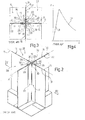
- Frame 5 shown partly in Figures 2 and 3 , comprises a lattice defined by a number of longitudinal members 10 (only one shown) extending in respective parallel directions A, and by a number of cross members 11 (only one shown) extending in respective parallel directions B intersecting directions A perpendicularly at a number of nodes 12 (only one shown).
- Cross members 11 are interrupted at each node 12 to avoid interfering with longitudinal members 10, and are fixed to longitudinal members 10, at each node 12, by an anchoring device 13 (only one shown in detail).
- longitudinal members 10 are defined by elongated flat walls, and are bounded, on opposite sides of direction A, by respective surfaces 21, 22.
- cross members 11 are defined by elongated flat walls, interrupted at the various nodes 12, and are bounded, on opposite sides of direction B, by respective surfaces 17, 18.
- anchoring device 13 comprises two pairs 27, 28 of connecting members 14, which are located on opposite sides of direction B to connect respective surfaces 17 and 18 to surfaces 21 and 22.
- connecting members 14 in pair 27 are located on opposite sides of direction A; a first connecting member 14 connects surface 17 to surface 21; and a second connecting member 14 connects surface 17 to surface 22.
- connecting members 14 in pair 28 are located on opposite sides of direction A; a first connecting member 14 connects surface 18 to surface 21; and a second connecting member 14 connects surface 18 to surface 22.
- connecting members 14 are identical, and each comprise a portion 29 and a portion 30, which are of equal extension, are perpendicular to each other, are fixed to longitudinal member 10 and cross member 11 respectively, are parallel to directions A and B respectively, and are therefore joined at node 12.
- Figure 4 shows a graph of the force F exerted at a given node 12 versus the displacement s of a point on deck 4 corresponding to given node 12, in the event of impact in a direction perpendicular to deck 4.
- the graph comprises a portion 31 increasing steadily to a maximum value corresponding to reversible elastic deformation of anchoring device 13; and a decreasing portion 32 following portion 31 and corresponding to permanent global deformation of anchoring device 13.
- Deck 4 is therefore only able to dissipate energy in the form of permanent deformation after transmitting the maximum force to tread surface 6, which may correspond to an intolerable amount of energy transmitted to the crew and passengers.
- helicopter certification regulations require that the helicopter deck be capable of absorbing a given amount of impact energy, without transmitting it to the crew or passengers.
- a deformable floor substructure for a helicopter as claimed in Claim 1.
- deck 35 comprises two walls 39 laterally joining tread surface 37 and portion 38, and curving to blend with respective sidewalls of fuselage 2 of helicopter 1.
- Frame 36 comprises a lattice defined by a number of longitudinal members 40, 41 extending in respective directions C parallel to one another and to walls 39, and by a number of cross members 42 extending between walls 39 and in respective directions D parallel to one another and perpendicular to directions C.
- longitudinal members 40 are located adjacent to walls 39, while longitudinal members 41 are interposed between longitudinal members 40.
- Directions C of longitudinal members 40 intersect directions D at a number of points or nodes 43 arranged in two lateral rows, and directions C of longitudinal members 41 intersect directions D at a number of further points or nodes 44 interposed between said rows.
- Each longitudinal member 40, 41 comprises an elongated flat wall, and is bounded, on opposite sides of relative direction C, by respective lateral surfaces 50, 51.
- each cross member 42 is defined by an elongated flat wall, which extends between walls 39 and has two opposite end portions 48 curving in a plane perpendicular to deck 35 and to longitudinal members 40, 41 so as to blend with walls 39; and each cross member 42 comprises a rectangular portion 49 interposed between portions 48 and elongated in said plane.
- Cross members 42 are interrupted at each node 43, 44 to avoid interfering with longitudinal members 40, 41, and are each bounded, on opposite sides of relative direction D, by respective surfaces 46, 47.
- cross members 42 are fixed to longitudinal members 41, at each node 44, by respective anchoring devices 52.
- Each anchoring device 52 comprises at least one local permanent deformation section 54 (indicated as a whole in Figure 6 ) crosswise to deck 35 and for dissipating the energy transmitted to deck 35 in the event of impact.
- each anchoring device 52 has a weak point at section 54, so that section 54 is permanently deformed and so dissipates energy at impact force values incapable of permanently deforming anchoring device 52 as a whole.
- anchoring devices 52 fix cross members 42 to longitudinal members 41 at respective nodes 44, and further anchoring devices fix cross members 42 to longitudinal members 40 at respective nodes 43.
- each anchoring device 52 advantageously has a closed polygonal contour 55 surrounding relative node 44 at a predetermined distance.
- each anchoring device 52 is symmetrical with respect to its own axis E - which is perpendicular to deck 35, when the anchoring device is fixed - and is of constant section in planes perpendicular to axis E.
- contour 55 surrounds relative node 44 at a predetermined distance which is less than the axial extension of anchoring device 52 and greater than the thickness of contour 55 measured perpendicularly to contour 55.
- anchoring device 52 is therefore a thin-section solid with a closed contour 55, which, in the event of impact perpendicular to deck 35, is subjected to compressive stress.
- compressed thin-section solids give rise to undulated permanent deformation lines parallel to the direction of the compressive force, and which, due to local elastic instability, are generated at an imperfectly shaped section of the solid substantially crosswise to the compressive force.
- Each anchoring device 52 is therefore permanently deformed at the section indicated as a whole by 54, which has shape imperfections not shown, so that the energy acquired during impact is dissipated by each anchoring device 52 as of low transmitted force values withstandable by the crew and passengers.
- contour 55 of each anchoring device 52 is defined by two pairs 56, 57 of connecting members 58, which are located on opposite sides of relative direction D and connect surfaces 46 and 47 of relative cross member 42 respectively to surfaces 50 and 51 of relative longitudinal member 41.
- connecting members 58 in pair 56 are located on opposite sides of direction C; one of connecting members 58 connects surface 46 to surface 50; and the other connecting member 58 connects surface 46 to surface 51.
- connecting members 58 in pair 57 are located on opposite sides of direction C; one of connecting members 58 connects surface 47 to surface 50; and the other connecting member 58 connects surface 47 to surface 51.
- connecting members 58 are identical, and each comprise, at opposite ends, a flat portion 60 and a flat portion 61 extending in directions perpendicular to each other, and a flat portion 62 extending obliquely with respect to portions 60 and 61.
- Portions 60 and 61 are fixed to relative longitudinal member 41 and relative cross member 42 respectively at a predetermined distance from relative node 44, so that portion 62 is also a predetermined distance from node 44.
- each anchoring device 52 is therefore defined by portions 62 of the four connecting members 58 surrounding relative node 44.
- each connecting member 58 facilitates permanent deformation of anchoring device 52 following deformation of section 54. That is, by virtue of contour 55 surrounding node 44 at a predetermined distance, the force of the impact generates highly intense bending moments on portions 60, 61, 62, which are therefore permanently deformed - literally "crushed" - in the direction of relative axis E.
- each connecting member 58 is particularly advantageous by maximizing the bending moments on portions 60, 61, 62 with no need, between portions 60 and 61, for noncontinuous curved or polygonal portions which are difficult to produce.
- Figure 8 shows a graph of the force F exerted at a given node 44 versus the displacement s of a point on deck 35 corresponding to given node 44, in the event of impact in a direction perpendicular to deck 35.
- the graph comprises a portion 75 increasing steadily to a maximum force value corresponding to reversible elastic deformation of node 44; and a portion 76 following portion 75 and which first decreases and then oscillates about a mean value.
- the maximum force value is reached upon local deformation of section 54 due to local instability; and, after the maximum value, portion 76 oscillates and comprises a number of secondary maximum and minimum force values corresponding to gradual permanent deformation of respective portions of anchoring device 52 due to static yield.
- anchoring device 52 deforms permanently and transmits a lower force value than known anchoring device 13; and, in the event of impact, the total energy dissipated by deck 35 - as shown by the X axis in the Figure 8 graph - is greater than the energy dissipated by deck 4 - as shown the X axis in the Figure 4 graph - by virtue of portion 76 oscillating about a mean value.
- the maximum force value transmitted by deck 35 to tread surface 37 is reduced, by anchoring device 52 according to the invention deforming locally, due to local instability, at lower force values than those required to permanently deform known anchoring device 13 as a whole.
- deck 35 has proved highly effective in dissipating most of the impact energy, without transmitting force values intolerable to the crew and passengers, thus also conforming with certification regulations governing missions of given duration.
Landscapes
- Engineering & Computer Science (AREA)
- Mechanical Engineering (AREA)
- Aviation & Aerospace Engineering (AREA)
- General Engineering & Computer Science (AREA)
- Refuge Islands, Traffic Blockers, Or Guard Fence (AREA)
- Bridges Or Land Bridges (AREA)
- Road Paving Structures (AREA)
- Body Structure For Vehicles (AREA)
- Vibration Dampers (AREA)
Abstract
Description
- The present invention relates to a deformable floor substructure for a helicopter.
-
Number 1 inFigure 1 indicates as a whole a helicopter substantially comprising a fuselage 2 housing the crew and on-board equipment; and a rotor 3 projecting from a top portion of fuselage 2 and for generating a force by which to sustainhelicopter 1. - In more detail, on the opposite side to rotor 3, fuselage 2 is bounded by a deck 4 for supporting the crew and on-board equipment.
- More specifically, deck 4 is of known type, comprises a frame 5 for imparting to deck 4 the necessary structural strength to support the crew and on-board equipment, and defines a crew tread surface 6 on one side of frame 5, and, on the opposite side, a portion 7 of the outer surface of fuselage 2.
- Frame 5, shown partly in
Figures 2 and 3 , comprises a lattice defined by a number of longitudinal members 10 (only one shown) extending in respective parallel directions A, and by a number of cross members 11 (only one shown) extending in respective parallel directions B intersecting directions A perpendicularly at a number of nodes 12 (only one shown). -
Cross members 11 are interrupted at eachnode 12 to avoid interfering withlongitudinal members 10, and are fixed tolongitudinal members 10, at eachnode 12, by an anchoring device 13 (only one shown in detail). - More specifically,
longitudinal members 10 are defined by elongated flat walls, and are bounded, on opposite sides of direction A, byrespective surfaces cross members 11 are defined by elongated flat walls, interrupted at thevarious nodes 12, and are bounded, on opposite sides of direction B, byrespective surfaces - More specifically,
anchoring device 13 comprises twopairs members 14, which are located on opposite sides of direction B to connectrespective surfaces surfaces - More specifically, connecting
members 14 inpair 27 are located on opposite sides of direction A; a first connectingmember 14 connectssurface 17 tosurface 21; and a second connectingmember 14 connectssurface 17 tosurface 22. - Similarly, connecting
members 14 inpair 28 are located on opposite sides of direction A; a first connectingmember 14 connectssurface 18 tosurface 21; and a second connectingmember 14 connectssurface 18 tosurface 22. - More specifically, connecting
members 14 are identical, and each comprise aportion 29 and aportion 30, which are of equal extension, are perpendicular to each other, are fixed tolongitudinal member 10 andcross member 11 respectively, are parallel to directions A and B respectively, and are therefore joined atnode 12. -
Figure 4 shows a graph of the force F exerted at a givennode 12 versus the displacement s of a point on deck 4 corresponding to givennode 12, in the event of impact in a direction perpendicular to deck 4. - The graph comprises a
portion 31 increasing steadily to a maximum value corresponding to reversible elastic deformation ofanchoring device 13; and a decreasingportion 32 followingportion 31 and corresponding to permanent global deformation ofanchoring device 13. - More specifically, along
portion 31, the energy acquired by deck 4 during impact is transmitted back to tread surface 6, and from tread surface 6 to the crew and on-board equipment. - Along
portion 32, on the other hand, as opposed to being transmitted to tread surface 6, the energy acquired by deck 4 during impact is dissipated in the form of permanent deformation of deck 4. - Deck 4 is therefore only able to dissipate energy in the form of permanent deformation after transmitting the maximum force to tread surface 6, which may correspond to an intolerable amount of energy transmitted to the crew and passengers.
- A need is therefore felt in the industry to reduce the amount of energy transmitted by the deck to the tread surface, in the event of impact, to safeguard the crew and passengers.
- Moreover, for certain missions, helicopter certification regulations require that the helicopter deck be capable of absorbing a given amount of impact energy, without transmitting it to the crew or passengers.
- It is an object of the present invention to provide a deformable floor substructure for a helicopter, designed to meet the above requirements in a straightforward, low-cost manner.
- According to the present invention, there is provided a deformable floor substructure for a helicopter, as claimed in
Claim 1. - A preferred, non-limiting embodiment of the present invention will be described by way of example with reference to the accompanying drawings, in which:
-
Figure 1 shows a view in perspective, with parts removed for clarity, of a helicopter comprising a known deck; -
Figure 2 shows a larger-scale view in perspective of a detail ofFigure 1 ; -
Figure 3 shows a section along line III-III inFigure 2 ; -
Figure 4 shows a graph of the force exerted on a given area of theFigure 1 deck versus displacement of the area; -
Figure 5 shows a view in perspective of a deck in accordance with the teachings of the present invention; -
Figure 6 shows a larger-scale view in perspective of a detail of theFigure 5 deck; -
Figure 7 shows a section along line VII-VII inFigure 6 ; and -
Figure 8 shows a graph of the force exerted on a given area of theFigure 5 deck versus displacement of the area; -
Figure 5 shows acollapsible deck 35 ofhelicopter 1, which, like deck 4, substantially comprises aframe 36 for imparting to deck 35 the necessary structural strength to support the crew and on-board equipment, and defines, on opposite sides offrame 36, acrew tread surface 37 and aportion 38 of the outer surface of fuselage 2 ofhelicopter 1. - At opposite lateral ends,
deck 35 comprises twowalls 39 laterally joiningtread surface 37 andportion 38, and curving to blend with respective sidewalls of fuselage 2 ofhelicopter 1. -
Frame 36 comprises a lattice defined by a number oflongitudinal members walls 39, and by a number ofcross members 42 extending betweenwalls 39 and in respective directions D parallel to one another and perpendicular to directions C. - More specifically,
longitudinal members 40 are located adjacent towalls 39, whilelongitudinal members 41 are interposed betweenlongitudinal members 40. Directions C oflongitudinal members 40 intersect directions D at a number of points ornodes 43 arranged in two lateral rows, and directions C oflongitudinal members 41 intersect directions D at a number of further points ornodes 44 interposed between said rows. - Each
longitudinal member lateral surfaces - Like
longitudinal members cross member 42 is defined by an elongated flat wall, which extends betweenwalls 39 and has twoopposite end portions 48 curving in a plane perpendicular todeck 35 and tolongitudinal members walls 39; and eachcross member 42 comprises arectangular portion 49 interposed betweenportions 48 and elongated in said plane. -
Cross members 42 are interrupted at eachnode longitudinal members respective surfaces - As shown in more detail in
Figures 6 and 7 ,cross members 42 are fixed tolongitudinal members 41, at eachnode 44, byrespective anchoring devices 52. - Each
anchoring device 52 comprises at least one local permanent deformation section 54 (indicated as a whole inFigure 6 ) crosswise todeck 35 and for dissipating the energy transmitted todeck 35 in the event of impact. - More specifically, as explained in detail below, each
anchoring device 52 has a weak point atsection 54, so thatsection 54 is permanently deformed and so dissipates energy at impact force values incapable of permanently deforminganchoring device 52 as a whole. - The maximum force value transmitted by each
anchoring device 52 to treadsurface 37 without dissipating any energy is therefore extremely low, and lower than the maximum force value transmitted by knownanchoring devices 13, which dissipate energy by permanently deforming globally. - More specifically,
anchoring devices 52fix cross members 42 tolongitudinal members 41 atrespective nodes 44, and further anchoring devices fix crossmembers 42 tolongitudinal members 40 atrespective nodes 43. - More specifically, most of the weight of the crew and on-board equipment weighs on
nodes 44, and the rest onnodes 43. - With particular reference to
Figures 6 and 7 , eachanchoring device 52 advantageously has a closedpolygonal contour 55 surroundingrelative node 44 at a predetermined distance. - More specifically, each
anchoring device 52 is symmetrical with respect to its own axis E - which is perpendicular todeck 35, when the anchoring device is fixed - and is of constant section in planes perpendicular to axis E. - More specifically,
contour 55 surroundsrelative node 44 at a predetermined distance which is less than the axial extension ofanchoring device 52 and greater than the thickness ofcontour 55 measured perpendicularly tocontour 55. - As shown in
Figures 6 and 7 ,anchoring device 52 is therefore a thin-section solid with a closedcontour 55, which, in the event of impact perpendicular todeck 35, is subjected to compressive stress. - As is known, compressed thin-section solids give rise to undulated permanent deformation lines parallel to the direction of the compressive force, and which, due to local elastic instability, are generated at an imperfectly shaped section of the solid substantially crosswise to the compressive force.
- More specifically, the above deformation is produced under applied forces lower than those necessary to permanently deform the solid due to global instability or static yield.
- Each
anchoring device 52 is therefore permanently deformed at the section indicated as a whole by 54, which has shape imperfections not shown, so that the energy acquired during impact is dissipated by eachanchoring device 52 as of low transmitted force values withstandable by the crew and passengers. - More specifically,
contour 55 of eachanchoring device 52 is defined by twopairs members 58, which are located on opposite sides of relative direction D and connectsurfaces relative cross member 42 respectively tosurfaces longitudinal member 41. - More specifically, connecting
members 58 inpair 56 are located on opposite sides of direction C; one of connectingmembers 58 connectssurface 46 tosurface 50; and the other connectingmember 58 connectssurface 46 tosurface 51. - Similarly, connecting
members 58 inpair 57 are located on opposite sides of direction C; one of connectingmembers 58 connectssurface 47 tosurface 50; and the other connectingmember 58 connectssurface 47 tosurface 51. - More specifically, connecting
members 58 are identical, and each comprise, at opposite ends, aflat portion 60 and aflat portion 61 extending in directions perpendicular to each other, and aflat portion 62 extending obliquely with respect toportions -
Portions longitudinal member 41 andrelative cross member 42 respectively at a predetermined distance fromrelative node 44, so thatportion 62 is also a predetermined distance fromnode 44. - Closed
polygonal contour 55 of eachanchoring device 52 is therefore defined byportions 62 of the four connectingmembers 58 surroundingrelative node 44. - The arrangement of
portions member 58 facilitates permanent deformation ofanchoring device 52 following deformation ofsection 54. That is, by virtue ofcontour 55 surroundingnode 44 at a predetermined distance, the force of the impact generates highly intense bending moments onportions - The flat shape of
oblique portion 62 of each connectingmember 58 is particularly advantageous by maximizing the bending moments onportions portions -
Figure 8 shows a graph of the force F exerted at a givennode 44 versus the displacement s of a point ondeck 35 corresponding to givennode 44, in the event of impact in a direction perpendicular todeck 35. - The graph comprises a
portion 75 increasing steadily to a maximum force value corresponding to reversible elastic deformation ofnode 44; and aportion 76 followingportion 75 and which first decreases and then oscillates about a mean value. - Along
portion 75, the energy acquired bydeck 35 during impact is transmitted back totread surface 37, whereas, alongportion 76, as opposed to being transmitted totread surface 37, the energy acquired bydeck 35 is dissipated in the form of permanent deformation ofdeck 35. - More specifically, the maximum force value is reached upon local deformation of
section 54 due to local instability; and, after the maximum value,portion 76 oscillates and comprises a number of secondary maximum and minimum force values corresponding to gradual permanent deformation of respective portions ofanchoring device 52 due to static yield. - As can be seen by comparing the
Figure 4 and8 graphs,anchoring device 52 according to the invention deforms permanently and transmits a lower force value than knownanchoring device 13; and, in the event of impact, the total energy dissipated by deck 35 - as shown by the X axis in theFigure 8 graph - is greater than the energy dissipated by deck 4 - as shown the X axis in theFigure 4 graph - by virtue ofportion 76 oscillating about a mean value. - The maximum force value transmitted by
deck 35 to treadsurface 37 is reduced, by anchoringdevice 52 according to the invention deforming locally, due to local instability, at lower force values than those required to permanently deform known anchoringdevice 13 as a whole. - The force transmitted by
deck 35 to treadsurface 37 without dissipating any energy is therefore lower than that transmitted by deck 4 to tread surface 6, and therefore better tolerated by the crew and passengers. - The advantages of helicopter
collapsible deck 35 according to the present invention will be clear from the foregoing description. - In particular, by virtue of local permanent deformation of
sections 54 of anchoringdevices 52, in the event of impact,deck 35 has proved highly effective in dissipating most of the impact energy, without transmitting force values intolerable to the crew and passengers, thus also conforming with certification regulations governing missions of given duration. - Clearly, changes may be made to helicopter
collapsible deck 35 as described and illustrated herein without, however, departing from the scope as defined in the accompanying Claims.
Claims (4)
said anchoring device (52) comprising at least one local permanent deformation section (54) lying in a plane crosswise to said floor substructure (35) and for dissipating the energy transmitted to said floor substructure (35) in the event of impact;
said section (54) comprising a closed contour (55) surrounding said point (44) of intersection at a predetermined distance;
said contour (55) being defined by four elementary portions (58) arranged in pairs (56, 57); each pair (56, 57) being located on a respective side of said second direction (D), and connecting a respective lateral surface (46, 47) of said cross member (42) to respective lateral surfaces (50, 51) of said first longitudinal member (41); each elementary portion (58) in each pair (56, 57) being located on a respective side of said first direction (C) and connecting a said lateral surface (46, 47) of said cross member (42) to a respective said lateral surface (50, 51) of said first longitudinal member (41), and comprising at least one portion (62) crosswise to said first and second direction (C, D);
Applications Claiming Priority (1)
| Application Number | Priority Date | Filing Date | Title |
|---|---|---|---|
| EP05425743A EP1777155B1 (en) | 2005-10-21 | 2005-10-21 | Deformable floor substructure for a helicopter |
Related Parent Applications (1)
| Application Number | Title | Priority Date | Filing Date |
|---|---|---|---|
| EP05425743A Division EP1777155B1 (en) | 2005-10-21 | 2005-10-21 | Deformable floor substructure for a helicopter |
Publications (2)
| Publication Number | Publication Date |
|---|---|
| EP1930237A1 true EP1930237A1 (en) | 2008-06-11 |
| EP1930237B1 EP1930237B1 (en) | 2009-07-29 |
Family
ID=35670851
Family Applications (2)
| Application Number | Title | Priority Date | Filing Date |
|---|---|---|---|
| EP05425743A Expired - Lifetime EP1777155B1 (en) | 2005-10-21 | 2005-10-21 | Deformable floor substructure for a helicopter |
| EP08151467A Expired - Lifetime EP1930237B1 (en) | 2005-10-21 | 2005-10-21 | Deformable floor substructure for a helicopter |
Family Applications Before (1)
| Application Number | Title | Priority Date | Filing Date |
|---|---|---|---|
| EP05425743A Expired - Lifetime EP1777155B1 (en) | 2005-10-21 | 2005-10-21 | Deformable floor substructure for a helicopter |
Country Status (5)
| Country | Link |
|---|---|
| US (1) | US7845594B2 (en) |
| EP (2) | EP1777155B1 (en) |
| JP (1) | JP5095175B2 (en) |
| CA (2) | CA2831230C (en) |
| DE (2) | DE602005015772D1 (en) |
Cited By (1)
| Publication number | Priority date | Publication date | Assignee | Title |
|---|---|---|---|---|
| EP4570647A1 (en) | 2023-12-14 | 2025-06-18 | Airbus Operations (S.A.S.) | Device for absorbing energy by compression, aircraft comprising at least one such device |
Families Citing this family (17)
| Publication number | Priority date | Publication date | Assignee | Title |
|---|---|---|---|---|
| EP1777155B1 (en) * | 2005-10-21 | 2008-12-10 | Agusta S.p.A. | Deformable floor substructure for a helicopter |
| US8079549B2 (en) * | 2008-06-30 | 2011-12-20 | EMBRAER—Empresa Brasileira de Aeronautica S.A. | Monolithic integrated structural panels especially useful for aircraft structures |
| JP5407773B2 (en) * | 2009-11-06 | 2014-02-05 | トヨタ自動車株式会社 | Energy absorption structure |
| JP5129827B2 (en) * | 2010-02-12 | 2013-01-30 | 三菱重工業株式会社 | Shock absorbing structure, shock absorbing structure manufacturing method, and moving body |
| DE102010062018B4 (en) * | 2010-11-26 | 2015-05-13 | Airbus Operations Gmbh | Support rod for supporting a floor structure of an aircraft |
| EP2876042B1 (en) * | 2013-11-20 | 2018-01-03 | AIRBUS HELICOPTERS DEUTSCHLAND GmbH | Helicopter airframe |
| EP2889212B1 (en) | 2013-12-30 | 2016-01-06 | AIRBUS HELICOPTERS DEUTSCHLAND GmbH | Subfloor structure with an integral hull for a rotary wing aircraft |
| CN104562987A (en) * | 2014-12-25 | 2015-04-29 | 贵州泰丰直升飞机维护工程有限公司 | Rectangular rapid splicing platform |
| CN104562960A (en) * | 2014-12-25 | 2015-04-29 | 贵阳高新泰丰航空航天科技有限公司 | Rigid rapid assembling platform |
| CN104562953A (en) * | 2014-12-25 | 2015-04-29 | 贵阳高新泰丰航空航天科技有限公司 | Rectangular rapid splicing platform |
| CN104594225A (en) * | 2014-12-25 | 2015-05-06 | 贵州通用航空有限责任公司 | Anti-slip quick-spliced platform |
| CN104562988A (en) * | 2014-12-25 | 2015-04-29 | 贵州通用航空有限责任公司 | Vibration-proof fast splicing platform made of flexible molecular materials |
| CN104594220A (en) * | 2014-12-25 | 2015-05-06 | 贵州通用航空有限责任公司 | Anti-static quick-spliced platform |
| CN104562989A (en) * | 2014-12-25 | 2015-04-29 | 贵州泰丰直升飞机维护工程有限公司 | Anti-vibration type rapid splicing platform |
| US10745098B2 (en) * | 2017-09-05 | 2020-08-18 | The Boeing Company | Energy-absorbing under-floor airframe |
| FR3156752A1 (en) * | 2023-12-14 | 2025-06-20 | Airbus Operations (S.A.S.) | Aircraft comprising at least one removable compression energy absorption device |
| FR3159588B1 (en) * | 2024-02-23 | 2026-04-17 | Airbus Operations Sas | Compression energy absorption device comprising star-shaped absorption tubes; aircraft comprising at least one such device |
Citations (2)
| Publication number | Priority date | Publication date | Assignee | Title |
|---|---|---|---|---|
| US4593870A (en) * | 1983-09-09 | 1986-06-10 | Bell Helicopter Textron Inc. | Energy absorbing composite aircraft structure |
| US5069318A (en) * | 1989-12-26 | 1991-12-03 | Mcdonnell Douglas Corporation | Self-stabilized stepped crashworthy stiffeners |
Family Cites Families (10)
| Publication number | Priority date | Publication date | Assignee | Title |
|---|---|---|---|---|
| JPS5125368Y2 (en) * | 1972-11-14 | 1976-06-29 | ||
| US4292375A (en) * | 1979-05-30 | 1981-09-29 | The United States Of America As Represented By The Administrator Of The National Aeronautics And Space Administration | Superplastically formed diffusion bonded metallic structure |
| US5301900A (en) * | 1990-12-12 | 1994-04-12 | Groen Henry J | Autogyro aircraft |
| JPH08197668A (en) * | 1995-01-23 | 1996-08-06 | Honda Motor Co Ltd | Laminated structure of fiber reinforced resin |
| DE69529453T2 (en) * | 1994-12-26 | 2003-10-02 | Honda Giken Kogyo K.K., Tokio/Tokyo | Multi-layer plate made of fiber-reinforced plastic, and shock-absorbing structure |
| DE19922295C1 (en) * | 1999-05-14 | 2000-07-27 | Eurocopter Deutschland | Underfloor structure of fuselage cell for helicopter is connected with floor and outer fuselage shell, comprising interconnected longitudinal and crossbearers |
| JP3888630B2 (en) * | 2002-12-04 | 2007-03-07 | 川崎重工業株式会社 | Energy absorbing member and helicopter impact resistant structure using the same |
| US7389860B2 (en) * | 2004-03-29 | 2008-06-24 | The Texas A&M University System | Energy absorbing device having notches and pre-bent sections |
| JP4520367B2 (en) * | 2005-06-07 | 2010-08-04 | 川崎重工業株式会社 | Impact structure of aircraft |
| EP1777155B1 (en) * | 2005-10-21 | 2008-12-10 | Agusta S.p.A. | Deformable floor substructure for a helicopter |
-
2005
- 2005-10-21 EP EP05425743A patent/EP1777155B1/en not_active Expired - Lifetime
- 2005-10-21 DE DE602005015772T patent/DE602005015772D1/en not_active Expired - Lifetime
- 2005-10-21 EP EP08151467A patent/EP1930237B1/en not_active Expired - Lifetime
- 2005-10-21 DE DE602005011634T patent/DE602005011634D1/en not_active Expired - Lifetime
-
2006
- 2006-10-20 US US11/584,463 patent/US7845594B2/en active Active
- 2006-10-20 CA CA2831230A patent/CA2831230C/en not_active Expired - Fee Related
- 2006-10-20 CA CA2565010A patent/CA2565010C/en not_active Expired - Fee Related
- 2006-10-20 JP JP2006286639A patent/JP5095175B2/en not_active Expired - Fee Related
Patent Citations (2)
| Publication number | Priority date | Publication date | Assignee | Title |
|---|---|---|---|---|
| US4593870A (en) * | 1983-09-09 | 1986-06-10 | Bell Helicopter Textron Inc. | Energy absorbing composite aircraft structure |
| US5069318A (en) * | 1989-12-26 | 1991-12-03 | Mcdonnell Douglas Corporation | Self-stabilized stepped crashworthy stiffeners |
Non-Patent Citations (3)
| Title |
|---|
| KINDERVATER C M: "CRASHRESISTANT COMPOSITE HELICOPTER STRUCTURAL CONCEPTS - THERMOSETAND THERMOPLASTIC CORRUGATED WEB DESIGNS", AHS NATIONAL TECHNICAL SPECIALISTS MEETING ON ADVANCED ROTORCRAFT STRUCTURES. PROCEEDINGS, 30 October 1995 (1995-10-30), pages 1 - 18, XP001051583 * |
| LESTARI W ET AL: "DEVELOPMENT OF A TRIGGER MECHANISM TO REDUCE PEAK FORCES IN CRASH LOADED COMPOSITE SINE-WAVE SPARS", EUROPEAN ROTORCRAFT FORUM, AMSTERDAM, NL, 4 October 1994 (1994-10-04), pages 107 - 1, XP001020746 * |
| LESTARI W.: "Crashworthiness Study of a Generic Compsite Helicopter Subfloor Structure", NLR TECNICAL REPORT TR 93590 L, 4 January 1994 (1994-01-04), XP009097693 * |
Cited By (3)
| Publication number | Priority date | Publication date | Assignee | Title |
|---|---|---|---|---|
| EP4570647A1 (en) | 2023-12-14 | 2025-06-18 | Airbus Operations (S.A.S.) | Device for absorbing energy by compression, aircraft comprising at least one such device |
| FR3156751A1 (en) * | 2023-12-14 | 2025-06-20 | Airbus Operations (S.A.S.) | Compression energy absorption device, aircraft comprising at least one such device |
| US12384512B2 (en) | 2023-12-14 | 2025-08-12 | Airbus Operations (S.A.S.) | Device for absorbing energy by compression, aircraft comprising at least one such device |
Also Published As
| Publication number | Publication date |
|---|---|
| EP1777155B1 (en) | 2008-12-10 |
| JP5095175B2 (en) | 2012-12-12 |
| DE602005011634D1 (en) | 2009-01-22 |
| EP1777155A1 (en) | 2007-04-25 |
| CA2831230A1 (en) | 2007-04-21 |
| CA2565010C (en) | 2014-06-10 |
| US7845594B2 (en) | 2010-12-07 |
| US20070114331A1 (en) | 2007-05-24 |
| CA2565010A1 (en) | 2007-04-21 |
| CA2831230C (en) | 2014-08-26 |
| DE602005015772D1 (en) | 2009-09-10 |
| JP2007112432A (en) | 2007-05-10 |
| EP1930237B1 (en) | 2009-07-29 |
Similar Documents
| Publication | Publication Date | Title |
|---|---|---|
| EP1930237B1 (en) | Deformable floor substructure for a helicopter | |
| EP3856631B1 (en) | Uav with protective outer cage | |
| US9995359B2 (en) | Deformable structure for absorption of energy from mechanical and/or acoustic impacts | |
| US9194452B2 (en) | High stiffness vibration damping apparatus, methods and systems | |
| EP1577153A2 (en) | Energy absorbing device for a vehicle seat | |
| US7967118B2 (en) | Impact absorber device | |
| US8770513B2 (en) | Resilient aircraft engine mounts and aircraft engine mounting systems including the same | |
| CN108290634B (en) | Fastening device for a component to be fastened to a rail of a floor structure in an aircraft interior | |
| US20090267391A1 (en) | Energy absorber element | |
| ES2711074T3 (en) | Elongated structures and related sets | |
| RU2509680C1 (en) | Assy of interaction of stresses, particularly, assy of interaction of loads for aircraft reclined door | |
| CN103221294B (en) | Crash structures for motor vehicles | |
| US20180134365A1 (en) | Aircraft component comprising a chiral lattice | |
| CN116119024B (en) | Aircraft Test Platform and Its Design Method | |
| CN110294097A (en) | A kind of novel cellular energy-absorbing buffer device of born of the same parents' lattice | |
| JP2012500155A (en) | Connecting wings to aircraft fuselage | |
| CN112993457A (en) | End stabilizer for high-voltage battery structural part | |
| US20210003252A1 (en) | Pressure vessel having substantially flat panel | |
| CN109421915B (en) | Energy absorbing underfloor unit | |
| WO2019203229A1 (en) | Landing device and stiffened member | |
| US9764816B2 (en) | Sliding connection between the floor structure and the hull structure of an aircraft | |
| CA3055737C (en) | An attachment for suspending aircraft engine | |
| JP2005075344A (en) | Automobile bumper | |
| JP4520367B2 (en) | Impact structure of aircraft | |
| KR102067573B1 (en) | A vibration filter mechanism for arranging between a piece of equipment and an aircraft fuselage, and a seat fitted with such a mechanism |
Legal Events
| Date | Code | Title | Description |
|---|---|---|---|
| PUAI | Public reference made under article 153(3) epc to a published international application that has entered the european phase |
Free format text: ORIGINAL CODE: 0009012 |
|
| AC | Divisional application: reference to earlier application |
Ref document number: 1777155 Country of ref document: EP Kind code of ref document: P |
|
| AK | Designated contracting states |
Kind code of ref document: A1 Designated state(s): AT BE BG CH CY CZ DE DK EE ES FI FR GB GR HU IE IS IT LI LT LU LV MC NL PL PT RO SE SI SK TR |
|
| AX | Request for extension of the european patent |
Extension state: AL BA HR MK RS |
|
| 17P | Request for examination filed |
Effective date: 20081008 |
|
| 17Q | First examination report despatched |
Effective date: 20081110 |
|
| GRAP | Despatch of communication of intention to grant a patent |
Free format text: ORIGINAL CODE: EPIDOSNIGR1 |
|
| AKX | Designation fees paid |
Designated state(s): DE FR GB IT |
|
| GRAS | Grant fee paid |
Free format text: ORIGINAL CODE: EPIDOSNIGR3 |
|
| GRAA | (expected) grant |
Free format text: ORIGINAL CODE: 0009210 |
|
| RAP1 | Party data changed (applicant data changed or rights of an application transferred) |
Owner name: AGUSTA S.P.A. |
|
| AC | Divisional application: reference to earlier application |
Ref document number: 1777155 Country of ref document: EP Kind code of ref document: P |
|
| AK | Designated contracting states |
Kind code of ref document: B1 Designated state(s): DE FR GB IT |
|
| REG | Reference to a national code |
Ref country code: GB Ref legal event code: FG4D |
|
| REF | Corresponds to: |
Ref document number: 602005015772 Country of ref document: DE Date of ref document: 20090910 Kind code of ref document: P |
|
| PLBE | No opposition filed within time limit |
Free format text: ORIGINAL CODE: 0009261 |
|
| STAA | Information on the status of an ep patent application or granted ep patent |
Free format text: STATUS: NO OPPOSITION FILED WITHIN TIME LIMIT |
|
| 26N | No opposition filed |
Effective date: 20100503 |
|
| REG | Reference to a national code |
Ref country code: FR Ref legal event code: PLFP Year of fee payment: 11 |
|
| REG | Reference to a national code |
Ref country code: FR Ref legal event code: PLFP Year of fee payment: 12 |
|
| REG | Reference to a national code |
Ref country code: FR Ref legal event code: PLFP Year of fee payment: 13 |
|
| REG | Reference to a national code |
Ref country code: FR Ref legal event code: PLFP Year of fee payment: 14 |
|
| REG | Reference to a national code |
Ref country code: DE Ref legal event code: R082 Ref document number: 602005015772 Country of ref document: DE Representative=s name: ZENZ PATENTANWAELTE PARTNERSCHAFT MBB, DE Ref country code: DE Ref legal event code: R081 Ref document number: 602005015772 Country of ref document: DE Owner name: LEONARDO S.P.A., IT Free format text: FORMER OWNER: AGUSTA S.P.A., SAMARATE, IT |
|
| P01 | Opt-out of the competence of the unified patent court (upc) registered |
Effective date: 20231005 |
|
| PGFP | Annual fee paid to national office [announced via postgrant information from national office to epo] |
Ref country code: DE Payment date: 20241029 Year of fee payment: 20 |
|
| PGFP | Annual fee paid to national office [announced via postgrant information from national office to epo] |
Ref country code: GB Payment date: 20241023 Year of fee payment: 20 |
|
| PGFP | Annual fee paid to national office [announced via postgrant information from national office to epo] |
Ref country code: FR Payment date: 20241025 Year of fee payment: 20 |
|
| PGFP | Annual fee paid to national office [announced via postgrant information from national office to epo] |
Ref country code: IT Payment date: 20241003 Year of fee payment: 20 |
|
| REG | Reference to a national code |
Ref country code: DE Ref legal event code: R071 Ref document number: 602005015772 Country of ref document: DE |
|
| REG | Reference to a national code |
Ref country code: GB Ref legal event code: PE20 Expiry date: 20251020 |