EP1930233A2 - Suspension controller and vehicle - Google Patents
Suspension controller and vehicle Download PDFInfo
- Publication number
- EP1930233A2 EP1930233A2 EP20070254695 EP07254695A EP1930233A2 EP 1930233 A2 EP1930233 A2 EP 1930233A2 EP 20070254695 EP20070254695 EP 20070254695 EP 07254695 A EP07254695 A EP 07254695A EP 1930233 A2 EP1930233 A2 EP 1930233A2
- Authority
- EP
- European Patent Office
- Prior art keywords
- damping force
- suspension system
- speed
- threshold
- vehicle
- Prior art date
- Legal status (The legal status is an assumption and is not a legal conclusion. Google has not performed a legal analysis and makes no representation as to the accuracy of the status listed.)
- Granted
Links
Images







Classifications
-
- B—PERFORMING OPERATIONS; TRANSPORTING
- B62—LAND VEHICLES FOR TRAVELLING OTHERWISE THAN ON RAILS
- B62K—CYCLES; CYCLE FRAMES; CYCLE STEERING DEVICES; RIDER-OPERATED TERMINAL CONTROLS SPECIALLY ADAPTED FOR CYCLES; CYCLE AXLE SUSPENSIONS; CYCLE SIDECARS, FORECARS, OR THE LIKE
- B62K25/00—Axle suspensions
- B62K25/04—Axle suspensions for mounting axles resiliently on cycle frame or fork
-
- B—PERFORMING OPERATIONS; TRANSPORTING
- B60—VEHICLES IN GENERAL
- B60G—VEHICLE SUSPENSION ARRANGEMENTS
- B60G17/00—Resilient suspensions having means for adjusting the spring or vibration-damper characteristics, for regulating the distance between a supporting surface and a sprung part of vehicle or for locking suspension during use to meet varying vehicular or surface conditions, e.g. due to speed or load
- B60G17/015—Resilient suspensions having means for adjusting the spring or vibration-damper characteristics, for regulating the distance between a supporting surface and a sprung part of vehicle or for locking suspension during use to meet varying vehicular or surface conditions, e.g. due to speed or load the regulating means comprising electric or electronic elements
- B60G17/016—Resilient suspensions having means for adjusting the spring or vibration-damper characteristics, for regulating the distance between a supporting surface and a sprung part of vehicle or for locking suspension during use to meet varying vehicular or surface conditions, e.g. due to speed or load the regulating means comprising electric or electronic elements characterised by their responsiveness, when the vehicle is travelling, to specific motion, a specific condition, or driver input
- B60G17/0164—Resilient suspensions having means for adjusting the spring or vibration-damper characteristics, for regulating the distance between a supporting surface and a sprung part of vehicle or for locking suspension during use to meet varying vehicular or surface conditions, e.g. due to speed or load the regulating means comprising electric or electronic elements characterised by their responsiveness, when the vehicle is travelling, to specific motion, a specific condition, or driver input mainly during accelerating or braking
-
- B—PERFORMING OPERATIONS; TRANSPORTING
- B60—VEHICLES IN GENERAL
- B60G—VEHICLE SUSPENSION ARRANGEMENTS
- B60G17/00—Resilient suspensions having means for adjusting the spring or vibration-damper characteristics, for regulating the distance between a supporting surface and a sprung part of vehicle or for locking suspension during use to meet varying vehicular or surface conditions, e.g. due to speed or load
- B60G17/06—Characteristics of dampers, e.g. mechanical dampers
- B60G17/08—Characteristics of fluid dampers
-
- B—PERFORMING OPERATIONS; TRANSPORTING
- B60—VEHICLES IN GENERAL
- B60G—VEHICLE SUSPENSION ARRANGEMENTS
- B60G2400/00—Indexing codes relating to detected, measured or calculated conditions or factors
- B60G2400/20—Speed
- B60G2400/204—Vehicle speed
-
- B—PERFORMING OPERATIONS; TRANSPORTING
- B60—VEHICLES IN GENERAL
- B60G—VEHICLE SUSPENSION ARRANGEMENTS
- B60G2400/00—Indexing codes relating to detected, measured or calculated conditions or factors
- B60G2400/25—Stroke; Height; Displacement
- B60G2400/252—Stroke; Height; Displacement vertical
-
- B—PERFORMING OPERATIONS; TRANSPORTING
- B60—VEHICLES IN GENERAL
- B60G—VEHICLE SUSPENSION ARRANGEMENTS
- B60G2400/00—Indexing codes relating to detected, measured or calculated conditions or factors
- B60G2400/30—Propulsion unit conditions
- B60G2400/33—Throttle position
-
- B—PERFORMING OPERATIONS; TRANSPORTING
- B60—VEHICLES IN GENERAL
- B60G—VEHICLE SUSPENSION ARRANGEMENTS
- B60G2800/00—Indexing codes relating to the type of movement or to the condition of the vehicle and to the end result to be achieved by the control action
- B60G2800/16—Running
- B60G2800/164—Heaving; Squatting
-
- B—PERFORMING OPERATIONS; TRANSPORTING
- B62—LAND VEHICLES FOR TRAVELLING OTHERWISE THAN ON RAILS
- B62K—CYCLES; CYCLE FRAMES; CYCLE STEERING DEVICES; RIDER-OPERATED TERMINAL CONTROLS SPECIALLY ADAPTED FOR CYCLES; CYCLE AXLE SUSPENSIONS; CYCLE SIDECARS, FORECARS, OR THE LIKE
- B62K25/00—Axle suspensions
- B62K25/04—Axle suspensions for mounting axles resiliently on cycle frame or fork
- B62K2025/044—Suspensions with automatic adjustment
Definitions
- the present invention relates to a suspension controller and a vehicle.
- a vehicle can suppress a squat (a downward deflection) of the vehicle body during acceleration by controlling a damping force of a suspension system (for example, refer to JP-B Hei 2-14206 ).
- a squat a downward deflection
- Such a vehicle has a facility for detecting that the opening speed of a throttle valve is equal to or higher than a predefined value and that the throttle valve is being opened suddenly. When the throttle valve is opened suddenly, the damping force of the suspension system is changed to suppress the squat.
- An object of an embodiment of the present invention in view of such situation described above, is to provide a suspension controller for improving ride comfort and driving stability and a vehicle provided with such a suspension controller.
- the suspension controller according to a first aspect of the invention is adapted to be mounted on a vehicle having:
- the suspension controller according to a second aspect of the invention is adapted to be mounted on a vehicle having:
- the suspension controller is mounted on a vehicle having an engine, a throttle valve for adjusting the amount of an air intake of the engine, a throttle angle detection apparatus for detecting an angle of the throttle valve, a vehicle speed sensor for detecting a vehicle speed, a front wheel, a rear wheel, a front wheel side suspension system for absorbing an impact on the front wheel, and a rear wheel side suspension system for absorbing the impact on the rear wheel in order to control each of damping forces on an expansion side and on a contraction side in the front wheel side suspension system and in the rear wheel side suspension system, having an opening speed calculation device for calculating an opening speed of the throttle valve on the basis of a detection result of the throttle angle detection apparatus, a squat suppression device for setting either or both of the damping force on the expansion side of the front wheel side suspension system and the damping force on the contraction side of the rear wheel suspension device higher than the damping force of a time when the opening speed is less than a first threshold, and a first threshold setting device for setting the first
- the squat suppression control for suppressing a squat of the vehicle is executed. Either or both of the damping force on the expansion side of the front wheel side suspension system and the damping force on the contraction side of the rear wheel side suspension system are set high in the squat suppression control.
- the first threshold is set corresponding to the vehicle speed in the suspension controller. In this constitution, the opening speed of the throttle valve while the squat suppression control is executed can be set according to the vehicle speed. As a result, it is possible to improve ride comfort and driving stability.
- the suspension controller is mounted on a vehicle having an engine, a throttle valve for adjusting the amount of an air intake of the engine, a throttle angle detection apparatus for detecting the angle of the throttle valve, a vehicle speed sensor for detecting a vehicle speed, a front wheel, a rear wheel, a front wheel side suspension system for absorbing an impact on the front wheel, and a rear wheel side suspension system for absorbing an impact on the rear wheel in order to control each of damping forces on an expansion side and on a contraction side in the front wheel side suspension system and in the rear wheel side suspension system, having a shutting speed calculation device for calculating a shutting speed of the throttle valve on the basis of a detection result of the throttle angle detection apparatus, a diving suppression device for setting either or both of the damping force on the contraction side of the front wheel side suspension system and the damping force on the expansion side of the rear wheel suspension device higher than the damping force of a time when the shutting speed is less than a third threshold while the shutting speed calculated by the shutting
- the diving suppression control is executed to suppress the diving described above. Either or both of the damping force on the contraction side of the front wheel side suspension system and the damping force on the expansion side of the rear wheel side suspension system are set high in the diving suppression control.
- the third threshold is set corresponding to the vehicle speed in the suspension controller. In this constitution, when the diving suppression control is executed, the shutting speed of the throttle valve can be set according to the vehicle speed. As a result, it is possible to improve ride comfort and driving stability.
- a method of controlling the front wheel suspension system and the rear wheel suspension system of a vehicle comprising increasing one or both of the damping force on expansion of the front wheel suspension system and the damping force on contraction of the rear wheel suspension system when the opening speed of the vehicle engine throttle is equal to or higher than a first threshold; and setting the first threshold corresponding to the vehicle speed.
- a method of controlling the front wheel suspension system and the rear wheel suspension system of a vehicle comprising increasing one or both of the damping force on contraction of the front wheel suspension system and the damping force on expansion of the rear wheel suspension system when the shutting speed of the vehicle engine throttle is equal to or higher than a third threshold; and setting the third threshold corresponding to the vehicle speed.
- squat and diving may be suppressed optimally. Moreover, it is possible to improve ride comfort and driving stability.
- a vehicle according to an embodiment of the present invention is a motorcycle 10.
- the motorcycle 10 has a body frame 11 forming a framework and a seat 16 on which a rider sits.
- the rider seated on the seat 16 drives the vehicle, straddling the body frame 11.
- the type of vehicle of the present invention is not limited to the type shown in FIG. 1 , and a so-called moped type vehicle can be used.
- the maximum speed, the displacement, the size of the vehicle, and so forth are not limited either.
- the vehicle is not limited to a motorcycle but can be another vehicle such as a four-wheel buggy.
- horizontal positions such as the front, the rear, the left, and the right refer to positions viewed by the rider sitting on the seat 16.
- the body frame 11 has a steering head pipe 12, a main frame 13 extending downward and rearward from the steering head pipe 12, and seat rails 14 on the left and right sides extending upward and rearward from a middle part of the main frame 13.
- a front wheel 19 is supported by the steering head pipe 12 via a front wheel suspension system 150.
- the front wheel suspension system 150 is a system for absorbing an impact applied to the front wheel 19 from a road or the like.
- the front wheel suspension system 150 has a hydraulic buffer 151 (refer to FIG. 3 ) and a contraction coil spring (not shown in the drawing) . This contraction coil spring absorbs an impact on the front wheel 19.
- the hydraulic buffer 151 generates the damping force on expansion and on contraction of the front wheel side suspension system 150.
- a fuel tank 20 and the seat 16 are supported on the seat rails 14.
- the seat 16 extends behind the fuel tank 20 in the direction of the rear ends of the seat rails 14.
- a pair of rear arm brackets 24 on the left and right sides are provided to the rear end of the main frame 13.
- the rear arm brackets 24 and others provided to the main frame 13 are parts of the body frame 11.
- the rear arm brackets 24 extend downward from the rear end of the main frame 13.
- a pivot shaft 38 is provided on the rear arm brackets 24.
- the front end of a rear arm 25 is swingably supported by the pivot shaft 38.
- a rear wheel 26 is supported by the rear end of the rear arm 25.
- the rear arm 25 is supported by the body frame 11 via a link mechanism 27 and a rear wheel suspension system 180.
- the rear wheel suspension system 180 is a system for absorbing an impact applied to the rear wheel 26 from a road or the like.
- the rear wheel suspension system 180 has the hydraulic buffer 151 (refer to FIG. 3 ) and a contraction coil spring (not shown in the drawing) . This contraction coil spring absorbs an impact on the rear wheel 26.
- the hydraulic buffer 151 generates the damping force on expansion and on contraction of the rear wheel side suspension system 180.
- An engine unit 28 for driving the rear wheel 26 is supported by the body frame 11.
- a crankcase 35 is suspendedly supported by the main frame 13.
- the engine unit 28 has a gasoline engine (not shown in the drawing).
- the engine of the engine unit 28 is not limited to an internal combustion engine such as a gasoline engine but can be an electric or other motor.
- the engine can be an engine provided by a combination of a gasoline engine and an electric motor. Accordingly, references herein to throttle valves, throttle valve angles, throttle opening settings and speeds and the like are intended to encompass the corresponding controls provided on an engine or motor which does not include a throttle or throttle valve, includes an alternative form of engine or intake control, or includes an alternate engine or motor speed control mechanism.
- the motorcycle 10 has a front cowl 33 and leg shields 34 on the left and right sides.
- the leg shields 34 are members for covering front sides of the feet of the rider.
- a brake pedal is provided to the lower part on the right side of the motorcycle 10 though not shown in the drawing.
- the brake pedal is for stopping the rear wheel 26.
- the front wheel 19 is stopped by operating a brake lever 103 (refer to FIG. 2 ) provided in the vicinity of a right grip 41R (an accelerator grip) on a handlebar 41.
- a clutch lever 104 is provided in the vicinity of a left grip 41L on the handlebar 41.
- a clutch 54 (refer to FIG. 2 ) is disengaged by operating the clutch lever 104.
- a shift pedal 115 is provided to the lower part on the left side of the motorcycle 10.
- a gear of a transmission 80 (refer to FIG. 2 ) is shifted by operating the shift pedal 115.
- FIG. 2 illustrates the constitution of the driveline system of the motorcycle 10 shown in FIG. 1 .
- the right grip 41R on the handlebar 41 constitutes the accelerator grip.
- An accelerator input sensor 42 is mounted on the accelerator grip.
- the accelerator input sensor 42 detects the amount of the operation on the right grip 41R (the amount of the operation of the accelerator) by the rider.
- An indicator 45 for displaying a current gear position is provided to the middle part of the handlebar 41.
- a shift position can be changed to a higher position or to a lower position between the neutral and the sixth gear, the highest gear, by an operation of the shift pedal 115 (refer to FIG. 1 ) in this embodiment.
- a throttle valve 46 is mounted on a throttle 47 constituting an intake air passage.
- a throttle drive actuator 49 is provided to the right end of a valve stem 48 of the throttle valve 46, and a throttle angle sensor 50 is provided to the left end.
- the throttle angle sensor 50 detects an angle of the throttle valve 46 (a throttle angle).
- This throttle angle sensor 50 is one embodiment of the throttle setting detection apparatus of the present invention. It is also within the scope of the present invention that the throttle angle is indirectly detected by the amount of operation of the accelerator detected with the accelerator input sensor 42. In a case like this, the accelerator input sensor 42 functions as the throttle setting detection apparatus of the present invention.
- An electronically controlled throttle device 51 is constituted with the right grip 41R as the accelerator grip, the throttle 47, the throttle drive actuator 49, and the throttle angle sensor 50.
- An engine speed sensor 53 is provided on the right side of the right end of a crankshaft 52 of the engine unit 28.
- the crankshaft 52 is connected to a main shaft 55 via the clutch 54 of a wet multiple disc type.
- the clutch 54 has a clutch housing 54a and a clutch boss 54b.
- a multiplicity of friction plates 54c is mounted in the clutch housing 54a.
- a multiplicity of clutch plates 54d is mounted on the clutch boss 54b.
- Each of the clutch plates 54d is disposed between adjacent friction plates 54c. The distances between the friction plates 54c and the clutch plates 54d vary by operating the clutch lever 104, so that the clutch 54 is engaged or disengaged.
- each of the shift gears 57 mounted on the main shaft 55 meshes with each of shift gears 59 mounted on a drive shaft 58.
- the drive shaft 58 is disposed in parallel with the main shaft 55.
- the shift gears 57 and the shift gears 59 are separately illustrated in FIG. 2 for convenience of description.
- the shift gears 57 and the shift gears 59 are mounted so that gears other than a selected gear rotate freely in relation to either or both of the main shaft 55 and the drive shaft 58. Accordingly, the drive force from the main shaft 55 to the drive shaft 58 is transmitted only via one selected pair of shift gears.
- the state in which one pair of the shift gears 57 and 59 meshes to transmit the drive force from the main shaft 55 to the drive shaft 58 is a gear-in state.
- An operation for shifting a gear by selecting the shift gears 57 and the shift gears 59 is made by using a shift cam 79.
- a plurality of cam grooves 60 (three in FIG. 2 ) is formed in the shift cam 79.
- Shift forks 61 are mounted in each of the cam grooves 60.
- Each of the shift forks 61 engages with a predefined gear in the shift gears 57 and 59 on the main shaft 55 and the drive shaft 58.
- a predefined gear in the shift gears 57 and 59 fitted in the main shaft 55 and the drive shaft 58 by a spline moves axially, being linked with the movement of the shift forks 61. Consequently, as the shift gears 57 and 59 having axially moved engage with some other shift gears 57 and 59 rotating freely in relation to the main shaft 55 and the drive shaft 58, gears are shifted.
- the transmission 80 is constituted with the shift gears 57 and 59 and the shift cam 79.
- a vehicle speed sensor 69 is provided to the drive shaft 58.
- a gear position sensor 70 for detecting the gear position is linked to the shift cam 79.
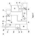
- FIG. 3 is a drawing for illustrating a simplified view of the constitution of the hydraulic buffer 151 provided to the front wheel suspension system 150 shown in FIG. 1 . Since the constitution of the hydraulic buffer 151 provided to the rear wheel suspension system 180 is generally similar to the constitution of the hydraulic buffer 151 of the front wheel suspension system 150, its description is omitted.
- the hydraulic buffer 151 has a hydraulic cylinder 153 and a piston 154 movably fitted together by insertion into the hydraulic cylinder 153.
- the hydraulic cylinder 153 has a tube 153a generally in a cylindrical shape. The lower end of the tube 153a is shut by a head cover 153b, and its upper end is shut by a rod cover 153c.
- the inside of the hydraulic cylinder 153 is filled with hydraulic fluid.
- the piston 154 is fitted together by insertion into the tube 153a.
- the inside of the hydraulic cylinder 153 is divided into a rod side oil chamber 157 and a head side oil chamber 158.
- the piston 154 moves to the side of the rod cover 153c (to the upper side in the drawing)
- the total length of the hydraulic buffer 151 expands. This process is referred to as an expansion process.
- the piston 154 moves to the side of the head cover 153b (to the lower side in the drawing)
- the total length of the hydraulic buffer 151 contracts. This process is referred to as a contraction process.
- a check valve 159 is provided to the piston 154.
- the check valve 159 passes hydraulic fluid from the head side oil chamber 158 only to the rod side oil chamber 157.
- a first oil passage 163 is connected to the rod side oil chamber 157 in the hydraulic cylinder 153.
- An expansion side damping force control valve 165 described below and a fixed throttle 166 for generating the damping force are parallely provided to the first oil passage 163.
- a second oil passage 164 is connected to the head side oil chamber 158 in the hydraulic cylinder 153.
- a check valve 167, a fixed throttle 168 for generating the damping force, and a contraction side damping force control valve 169 described below are parallely provided to the second oil passage 164.
- the first oil passage 163 is connected to a part between the head side oil chamber 158 and the check valve 167 in the second oil passage 164.
- An accumulator 170 is connected to the second oil passage 164.
- the accumulator 170 has a gas chamber 173 filled with high pressure gas, an oil chamber 171 filled with hydraulic fluid, and a movable partition 172 for separating the gas chamber 173 and the oil chamber 171.
- the second oil passage 164 is connected to the oil chamber 171 of the accumulator 170.
- This accumulator 170 urges the hydraulic fluid in the oil chamber 171 by the pressure of the high pressure gas in the gas chamber 173.
- the check valve 167 is connected so that the hydraulic fluid flows from the side of the accumulator 170 only to the head side oil chamber 158.
- the fixed throttles 166 and 168 are constituted with an orifice and a tabular valve.
- the fixed throttle 166 provided to the first oil passage 163 generates the damping force by the flow of the hydraulic fluid from the upper side to the lower side when the hydraulic buffer 151 is in an expansion process.
- the fixed throttle 168 provided to the second oil passage 164 generates the damping force by the flow of the hydraulic fluid from the lower side to the upper side when the hydraulic buffer 151 is in a contraction process.
- the expansion side damping force control valve 165 and the contraction side damping force control valve 169 pass the hydraulic fluid to the side of the accumulator 170 (to the side of a low pressure) when the oil pressure on the side of the hydraulic cylinder 153 (on the side of a high pressure) exceeds a predefined release pressure.
- the release pressure is increased or decreased by linear solenoids 174 and 178 provided in the expansion side damping force control valve 165 and in the contraction side damping force control valve 169 respectively.
- the expansion side damping force control valve 165 changes the damping force generated when a piston rod 155 is in the expansion process (the damping force of the expansion side) .
- the contraction side damping force control valve changes the damping force generated when the piston rod 155 is in the contraction process (the damping force of the contraction side).
- the linear solenoids 174 and 178 described above are operated and controlled by a suspension controller 100 shown in FIG. 4 .
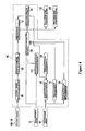
- FIG. 4 is a block diagram illustrating a simplified view of the constitution of the suspension controller 100.
- Stroke sensors 160 and 190, the throttle angle sensor 50, and the vehicle speed sensor 69 are provided as apparatuses for providing signals to the suspension controller 100.
- the stroke sensor 160 detects the amount of the stroke of the front wheel suspension system 150.
- the stroke sensor 190 detects the amount of the stroke of the rear wheel suspension system 180.
- the amounts of the strokes calculated by the stroke sensors 160 and 190 are input to a stroke speed calculation module 101 provided to the suspension controller 100 respectively.
- the stroke speed calculation module 101 calculates a stroke speed change of the front wheel suspension system 150 and the rear wheel side suspension system 180 on the basis of the input amounts of the strokes.
- the stroke speed change calculated in the stroke speed calculation module 101 is input to a standard damping force setting module 102 provided to the suspension controller 100.
- the standard damping force setting module 102 sets a standard damping force on the basis of the input stroke speed change.
- the standard damping force is one element for determining the damping force finally generated in the front wheel suspension system 150 and in the rear wheel suspension system 180 (a final damping force). Specifically, the sum of the standard damping force, an additional damping force described below, and a fixed damping force described below is the final damping force.
- a damping force determination module 111 connected to the standard damping force setting module 102 determines the final damping force.
- the throttle angle detected by the throttle angle sensor 50 is input to each of a throttle speed change calculation module 112 and a threshold comparison module 109 of the suspension controller 100 .
- the throttle speed change calculation module 112 calculates the speed change of the throttle angle on the basis of the input throttle angle.
- the speed change is referred to as an opening speed.
- the speed change is referred to as a shutting speed.
- the threshold comparison module 109 compares the speed change input from the throttle speed change calculation module 112 (the opening speed or the shutting speed) with the threshold in relation to the opening speed or the shutting speed set by an opening/shutting speed threshold setting module 108 described below (an opening speed threshold or a shutting speed threshold) .
- the threshold comparison module 109 compares the throttle angle input from the throttle angle sensor 50 with the threshold in relation to the throttle angle set by an opening threshold setting module described below (an angle threshold).
- a comparison result by the threshold comparison module 109 is input to an additional damping force setting module 110 of the suspension controller 100.
- the additional damping force setting module 110 determines whether an additional damping force is to be set or not on the basis of the comparison result.
- the additional damping force setting module 110 sets an additional damping force on the basis of a damping force map selected by a damping force map selection module 105 described below when having determined that an additional damping force is to be set.
- the additional damping force set by the additional damping force setting module 110 and the standard damping force set by the standard damping force setting module 102 are input to the damping force determination module 111 respectively.
- the damping force determination module 111 calculates the sum of the standard damping force, the additional damping force, and the fixed damping force input respectively. As mentioned above, the sum is the final damping force to be generated by the front wheel suspension system 150 and the rear wheel suspension system 180.
- the damping force determination module 111 provides the calculated damping force to the front wheel suspension system 150 and to the rear wheel side suspension system 180.
- the vehicle speed detected by the vehicle speed sensor 69 is input to each of the damping force map selection module 105, an angle threshold setting module 107, and the opening/shutting speed threshold setting module 108.
- the damping force map selection module 105, the angle threshold setting module 107, and the opening/shutting speed threshold setting module 108 are provided in the suspension controller 100.
- the damping force map selection module 105 selects a damping force map to be adopted from a plurality of types of damping force maps stored in a damping force map storage module 106 on the basis of the vehicle speed input from the vehicle speed sensor 69.
- a damping force map is a map for regulating the relation between the speed change of the throttle angle and the additional damping force as described below in detail.
- a multiplicity of types of damping force maps containing different relations between the speed change and the additional damping force is stored in the damping force map storage module 106.
- the angle threshold setting module 107 sets the angle threshold on the basis of the input vehicle speed.
- the angle threshold having been set is input to the threshold comparison module 109.
- This angle threshold having been input is the angle threshold to be compared with the throttle angle by the threshold comparison module 109.
- the opening/shutting speed threshold setting module 108 sets the opening speed threshold or the shutting speed threshold on the basis of the input vehicle speed.
- the opening/shutting speed threshold having been set is input to the threshold comparison module 109.
- the opening/shutting speed threshold having been input is the opening/shutting speed threshold to be compared with the speed change of the throttle angle by the threshold comparison module 109.
- FIG. 5 is a flow chart illustrating the flow of a damping force control processing.
- a step S50 determines whether the throttle valve 46 is being opened or shut.
- the suspension controller 100 determines whether the throttle angle is changing in the direction for opening the throttle valve 46 or in the direction for shutting the throttle valve 46.
- a squat suppression processing is executed in a step S100.
- a diving suppression processing is executed in a step S400. The squat suppression processing and the diving suppression processing will be described below in detail.
- FIG. 6 and FIG. 7 are flow charts illustrating the flow of the squat suppression processing called and executed in the step S100 of the flow chart shown in FIG. 5 .
- the squat suppression processing determines whether the condition for generating a squat is met or not on the basis of the opening speed and the throttle angle of the throttle valve 46. If the squat suppression processing determines that the condition is met, each of the front wheel suspension system 150 and the rear wheel suspension system 180 is controlled in order to suppress the squat.
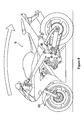
- a squat of the motorcycle 10 will be described with reference to FIG. 8 hereinafter.
- a squat occurs with the rear part of the vehicle body deflecting downward and the front part of the vehicle body deflecting upward when the accelerator is opened suddenly.
- the damping force control of the front wheel suspension system 150 and the rear wheel suspension system 180 is executed in order to suppress the squat when the condition for generating such a squat is met.
- a throttle angle is input from the throttle angle sensor 50 in a step S110 in FIG. 6 .
- a vehicle speed is input from the vehicle speed sensor 69 in a step S120.
- the amount of a stroke of the front wheel suspension system 150 and the amount of a stroke of the rear wheel suspension system 180 are input from the stroke sensors 160 and 190 respectively in a step S130.
- the opening speed of the throttle valve 46 is calculated in a step S140.
- the throttle speed change calculation module 112 of the suspension controller 100 calculates the opening speed of the throttle valve 46 on the basis of the throttle angle input from the processing in the step S110. Specifically, for example, the opening speed is calculated from the throttle angle input by the processing in the step S110 at an immediately previous time and the throttle angle input by the processing in the step S110 at a predefined time earlier than the immediately previous time.
- the throttle speed change calculation module 112 of the suspension controller 100 functions as an opening speed calculation or determination device of the present invention.
- the stroke speed is calculated in a step S150.
- the stroke speed calculation module 101 of the suspension controller 100 calculates each of the stroke speed of the front wheel suspension system 150 and the stroke speed of the rear wheel suspension system 180 on the basis of the amounts of the strokes of the front wheel suspension system 150 and the rear wheel suspension system 180 input from the processing in the step S130.
- a standard damping force is set in a step S160.
- the standard damping force setting module 102 of the suspension controller 100 sets the standard damping force of the front wheel suspension system 150 and the rear wheel suspension system 180 on the basis of the stroke speed calculated in the processing in the step S150. For example, when the calculated stroke speed is the speed in the direction of the expansion of a suspension system (the front wheel suspension system 150 or the rear wheel suspension system 180), a higher standard damping force of the expansion side is set as the stroke speed becomes higher. On the other hand, when the calculated stroke speed is the speed in the direction of the contraction of a suspension system, a higher standard damping force of the contraction side is set as the stroke speed becomes higher.
- the opening speed threshold is set in a step S170.
- the opening speed threshold is a threshold used for determining whether the squat suppression is executed or not in the processing in a step S190 described below.
- the opening/shutting speed threshold setting module 108 of the suspension controller 100 sets the opening speed threshold on the basis of the vehicle speed input from the processing in the step S120.
- the opening/shutting speed threshold setting module 108 of the suspension controller 100 functions as a first threshold setting device of the present invention for setting the first threshold (the opening speed threshold).
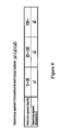
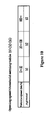
- An opening speed threshold setting table shown in FIG. 9 is referenced in the processing in the step S170.
- an opening speed threshold a1 is set if the vehicle speed is 0 (km/h) or higher and less than 30 (km/h).
- An opening speed threshold a2 (>al) is set if the vehicle speed is 30 (km/h) or higher and less than 100 (km/h) .
- An opening speed threshold a3 (>a2) is set if the vehicle speed is 100 (km/h) or higher. In other words, as the vehicle speed becomes lower, the lower opening speed threshold is set.
- the calculated opening speed and the opening speed threshold are compared in the processing in the step S190 described below.
- the squat suppression is executed if the condition in relation to a step S200 described below is met.
- the lower opening speed threshold is set as illustrated in FIG. 9 . Therefore, when the vehicle speed is low, the squat suppression is executed even if the calculated opening speed is relatively low in the embodiment.
- the squat suppression is not executed unless the calculated opening speed is relatively high.
- the squat suppression is executed in accordance with the relation between the vehicle speed and the opening speed for generating a squat in the embodiment. Consequently, it is possible to improve ride comfort and driving stability.
- an angle threshold is set in a step S180.
- the angle threshold is a threshold used for determining whether the squat suppression is to be executed or not in the processing in the step S200 described below.
- the squat suppression is executed in the embodiment.
- the angle threshold setting module 107 of the suspension controller 100 sets the angle threshold on the basis of the vehicle speed input from the processing in the step S120.
- the angle threshold setting module 107 of the suspension controller 100 functions as a second threshold setting device of the present invention for setting the second threshold (the angle threshold) .
- An angle threshold setting table shown in FIG. 10 is referenced in the processing in the step S180.
- an angle threshold b1 is set if the vehicle speed is 0 (km/h) or higher and less than 30 (km/h).
- An angle threshold b2 (>b1) is set if the vehicle speed is 30 (km/h) or higher and less than 100 (km/h).
- An angle threshold b3 (>b2) is set if the vehicle speed is 100 (km/h) or higher. In other words, as the vehicle speed becomes lower, a lower (angle) threshold is set.
- the squat described above occurs even if an accelerator is opened at a time when the throttle angle is relatively small.
- the vehicle speed is relatively high, such a squat does not occur unless an accelerator is opened at a time when the throttle angle is relatively large.
- the squat described above occurs even if an accelerator is opened at a time when the throttle angle is smaller.
- the input throttle angle and the angle threshold are compared in the processing in the step S200 described below.
- the squat suppression is executed.
- the lower angle threshold is set as illustrated in FIG. 10 . Therefore, when the vehicle speed is low, the squat suppression is executed even if the accelerator is opened at a time when the throttle angle is relatively small in the embodiment.
- the squat suppression is not executed unless the accelerator is opened at a time when the throttle angle is relatively large.
- the squat suppression is executed in accordance with the relation between the vehicle speed and the throttle angle for generating a squat by the operation of the accelerator in the embodiment. Consequently, it is possible to improve ride comfort and driving stability.
- the step S190 in FIG. 7 determines whether the opening speed is equal to or higher than the opening speed threshold or not.
- the threshold comparison module 109 of the suspension controller 100 determines whether the opening speed calculated in the processing in the step S140 is equal to or higher than the opening speed threshold or not.
- step S200 determines whether the throttle angle is equal to or larger than the angle threshold or not.
- the threshold comparison module 109 of the suspension controller 100 determines whether or not the throttle angle input from the processing in the step S110 is equal to or larger than the angle threshold set by the processing in the step S180.
- a first damping force map is selected in a step S210.
- the damping force map selection module 105 of the suspension controller 100 selects a first damping force map to be adopted from a plurality of types of the first damping force maps stored in the damping force map storage module 106 on the basis of the vehicle speed input from the processing in the step S120.
- the damping force map selection module 105 of the suspension controller 100 functions as a selection device of the present invention.
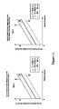
- FIG. 11 is a drawing illustrating the characteristic of a plurality of types of the first damping force maps stored in the damping force map storage module 106.
- the first damping force maps consist of a map A for regulating the relation between the opening speed and the additional damping force on the expansion side (on the expansion side of the front wheel) of the front wheel suspension system 150 (first additional damping forces D1) and a map B for regulating the relation between the opening speed and the additional damping force on the contraction side (on the contraction side of the rear wheel) of the rear wheel suspension system 180 (second additional damping forces D2).
- the map A1 is the map selected when the vehicle speed is equal to or higher than 0 (km/h) and less than 30 (km/h).
- the map A2 is the map selected when the vehicle speed is equal to or higher than 30 (km/h) and less than 100 (km/h).
- the map A3 is the map selected when the vehicle speed is equal to or higher than 100 (km/h).
- the map B1 is the map selected when the vehicle speed is equal to or higher than 0 (km/h) and less than 30 (km/h).
- the map B2 is the map selected when the vehicle speed is equal to or higher than 30 (km/h) and less than 100 (km/h).
- the map B3 is the map selected when the vehicle speed is equal to or higher than 100 (km/h).
- the three types of first damping force maps consisting of a first damping force map consisting of the map A1 and the map B1, a first damping force map consisting of the map A2 and the map B2, and a first damping force map consisting of the map A3 and the map 3 are stored in the damping force map storage module 106.
- the first damping force map consisting of the map A1 and the map B1 is selected, for example, when the input vehicle speed is 25 (km/h).
- the amount of the deflection of the squat is different between the case in which the vehicle speed is low and the case in which the vehicle speed is high. Specifically, when the vehicle speed is low, even if the speed of the operation for opening the accelerator is the same, the amount of the deflection is larger than that of the time when the vehicle speed is high.
- the first additional damping forces D1 set for the same opening speed gradually become larger in the order of the maps A3, A2, and A1.
- the second additional damping forces D2 set for same opening speed gradually become larger in the order of the maps B3, B2, and B1. Therefore, as the vehicle speed becomes lower, a first damping force map containing larger values to be set as a first additional damping force D1 and a second additional damping force D2 is selected. As described above, even if a squat generating a large deflection is generated by the operation for opening the accelerator at a time when the vehicle speed is low, a squat suppression strong enough to offset the deflection is executed in the embodiment.
- an additional damping force is set in a step S220.
- the additional damping force setting module 110 of the suspension controller 100 sets a first additional damping force D1 and a second additional damping force D2 on the basis of the opening speed calculated in the processing in the step S140.
- the first damping force map selected in the processing in the step S210 is referenced in the processing in the step S220.
- the values of the first additional damping forces D1 and the second additional damping forces D2 characteristically become larger in proportion to the opening speed in the three types of the first additional damping force maps.
- the deflection of the squat becomes larger.
- the values to be set as a first additional damping force D1 and a second additional damping force D2 become larger in proportion to the opening speed as illustrated in FIG. 11 .
- a stronger squat suppression is executed. Consequently, a squat suppression of appropriate strength can be executed corresponding to the amount of the deflection of a squat. As a result, it is possible to improve ride comfort and driving stability.
- a final damping force is determined in a step S230.
- the damping force determination module 111 of the suspension controller 100 calculates the sum of the standard damping force, the additional damping force, and a predefined fixed damping force DC as the final damping force.
- the final damping force of the front wheel suspension system 150 is calculated as the sum of the standard damping force set in the processing in the step S160, the first additional damping force D1 set in the processing in the step S220, and the predefined fixed damping force DC.
- the final damping force of the rear wheel suspension system 180 is calculated as the sum of the standard damping force set in the processing in the step S160, the second additional damping force D2 set in the processing in the step S220, and the predefined fixed damping force DC.
- the fixed damping force DC added to the standard damping force of the front wheel suspension system 150 and the fixed damping force DC added to the standard damping force of the rear wheel suspension system 180 can be the same value or can be different values.
- the first additional damping force D1 and the second additional damping force D2 in proportion to the opening speed are set as illustrated in FIG. 11 . Accordingly, when the opening speed is very low (when the operation for opening the accelerator is very slow), the first additional damping force D1 and the second additional damping force D2 to be added are also very small. In a case like this, the squat suppression force is extremely small. Consequently, the squat may not be optimally suppressed.
- the fixed damping force DC is added together with the first additional damping force D1 and the second additional damping force D2. Therefore, even when the opening speed is very low, the squat suppression force of a certain amount can be maintained, so that the squat is suppressed optimally. As a result, it is possible to improve ride comfort and driving stability.
- the procedure proceeds to a step S240. Specifically, if the step S190 determines that the opening speed is not equal to or higher than the opening speed threshold (less than the opening speed threshold) or if the step S200 determines that the throttle angle is not equal to or larger than the angle threshold (less than the angle threshold), the procedure proceeds to the step S240.
- the damping force determination module 111 of the suspension controller 100 determines the standard damping force set by the processing in the step S160 as the final damping force.
- the final damping forces of the front wheel suspension system 150 and the rear wheel suspension system 180 are set to the standard damping force.
- neither the additional damping force nor the fixed damping force DC is added.
- a suspension control is executed in a step S250.
- an operation control of the front wheel suspension system 150 and the rear wheel suspension system 180 (specifically, the operation control of the linear solenoids 174 and 178) is executed in order to generate the final damping force determined by the processing in the step S230 or in the step S240.
- the first additional damping force D1 and the fixed damping force DC are added to the standard damping force of the front wheel expansion side, and the second additional damping force D2 and the fixed damping force DC are added to the standard damping force of the rear wheel contraction side.
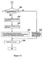
- FIG. 12 and FIG. 13 are flow charts illustrating the flow of the diving suppression processing called and executed in the step S400 of the flow chart shown in FIG. 5 .
- the diving suppression processing determines whether the condition for generating diving is met or not. When the diving suppression processing determines that the condition is met, each of the front wheel suspension system 150 and the rear wheel suspension system 180 is controlled in order to suppress diving.
- the diving suppression processing illustrated in FIG. 12 and in FIG. 13 have many steps similar to those of the squat suppression processing illustrated in FIG. 6 and in FIG. 7 .
- the description of the diving suppression processing will be mainly concentrated on differences from the squat suppression processing.
- steps S410, S420, and S430 are executed as illustrated in FIG. 12 .
- the processings are similar to the processings in the steps S110, S120, and S130 in FIG. 6 . Therefore, their description is omitted.
- the shutting speed of the throttle valve 46 is calculated in a step S440.
- the throttle speed change calculation module 112 of the suspension controller 100 calculates the shutting speed of the throttle valve 46 on the basis of the throttle angle input from the processing in the step S410. Specifically, for example, the shutting speed is calculated from the throttle angle input by the processing in the step S410 at an immediately previous time and the throttle angle input by the processing in the step S410 at a predefined time earlier than the immediately previous time.
- steps S450 and S460 are executed in sequence.
- the processings in the steps S450 and S460 are similar to the processings in the steps S150 and S160 in FIG. 6 . Therefore, their description is omitted.
- the shutting speed threshold is set in a step S470.
- the shutting speed threshold is a threshold used for determining whether the diving suppression is to be executed or not in the processing in a step S490 described below.
- the opening/shutting speed threshold setting module 108 of the suspension controller 100 sets the shutting speed threshold on the basis of the vehicle speed input from the processing in the step S420.
- a shutting speed threshold setting table shown in FIG. 15 is referenced in the processing in the step 5470.
- a shutting speed threshold c1 is set if the vehicle speed is 0 (km/h) or higher and less than 30 (km/h).
- a shutting speed threshold c2 (>c1) is set if the vehicle speed is 30 (km/h) or higher and less than 100 (km/h).
- a shutting speed threshold c3 (>c2) is set if the vehicle speed is 100 (km/h) or higher. In other words, as the vehicle speed becomes lower, the lower the shutting speed threshold is set.
- the calculated shutting speed and the shutting speed threshold are compared in the processing in the step S490 described below.
- the shutting speed is equal to or higher than the shutting speed threshold
- the diving suppression is executed.
- the lower shutting speed threshold is set as illustrated in FIG. 15 . Therefore, when the vehicle speed is low, the diving suppression is executed even if the calculated shutting speed is relatively low.
- the diving suppression is not executed unless the calculated shutting speed is relatively high.
- diving suppression is executed in accordance with the relation between the vehicle speed and the shutting speed for generating diving. Consequently, it is possible to improve ride comfort and driving stability.
- the step S490 in FIG. 13 determines whether the shutting speed is equal to or higher than the shutting speed threshold or not.
- the threshold comparison module 109 of the suspension controller 100 determines whether or not the shutting speed calculated in the processing in the step S440 is equal to or higher than the shutting speed threshold set by the processing in the step S470.
- a second damping force map is selected in a step S510.
- the damping force map selection module 105 of the suspension controller 100 selects a second damping force map to be adopted from a plurality of types of second damping force maps stored in the damping force map storage module 106 on the basis of the vehicle speed input from the processing in the step S420.
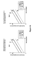
- FIG. 16 is a drawing illustrating the characteristics of a plurality of types of the second damping force maps stored in the damping force map storage module 106.
- the second damping force maps consist of a map C for regulating the relation between the shutting speed and the additional damping force on the contraction side of the front wheel suspension system 150 (third additional damping forces D3) and a map D for regulating the relation between the opening speed and the additional damping force on the expansion side of the rear wheel suspension system 180 (fourth additional damping forces D4).
- the map C1 is the map selected when the vehicle speed is equal to or higher than 0 (km/h) and less than 30 (km/h).
- the map C2 is the map selected when the vehicle speed is equal to or higher than 30 (km/h) and less than 100 (km/h).
- the map C3 is the map selected when the vehicle speed is equal to or higher than 100 (km/h).
- the map D1 is the map selected when the vehicle speed is equal to or higher than 0 (km/h) and less than 30 (km/h).
- the map D2 is the map selected when the vehicle speed is equal to or higher than 30 (km/h) and less than 100 (km/h).
- the map D3 is the map selected when the vehicle speed is equal to or higher than 100 (km/h).
- the three types of second damping force maps consisting of a second damping force map consisting of the map C1 and the map D1, a second damping force map consisting of the map C2 and the map D2, and a second damping force map consisting of the map C3 and the map D3 are stored in the damping force map storage module 106.
- the second damping force map consisting of the map C1 and the map B1 is selected, for example, when the input vehicle speed is 25 (km/h).
- the amount of the deflection of diving is different between the case in which the vehicle speed is low and the case in which the vehicle speed is high. Specifically, when the vehicle speed is low, even if the speed of the operation for shutting the accelerator is the same, the amount of the deflection is larger than that of the time when the vehicle speed is high.
- the third additional damping forces D3 set for the same shutting speed gradually becomes larger in the order of the maps C3, C2, and A1.
- the fourth additional damping forces D4 set for the same shutting speed gradually become larger in the order of the maps D3, D2, and D1. Therefore, as the vehicle speed becomes lower, a second damping force map containing larger values to be set as a third additional damping force D3 and a fourth additional damping force D4 is selected.
- a diving suppression strong enough to offset the deflection is executed in the embodiment.
- a diving suppression is softly executed. As a result, it is possible to improve ride comfort and driving stability.
- an additional damping force is set in a step S520.
- the additional damping force setting module 110 of the suspension controller 100 sets a third additional damping force D3 and a fourth additional damping force D4 on the basis of the shutting speed calculated in the processing in the step S440.
- the second damping force map selected in the processing in the step S510 is referenced in the processing in the step S520.
- the values of the third additional damping force D3 and the fourth additional damping force D4 characteristically become larger in proportion to the shutting speed in the three types of the second damping force maps.
- the deflection of the diving becomes larger.
- the values to be set as a third additional damping force D3 and a fourth additional damping force D4 become larger in proportion to the shutting speed as illustrated in FIG. 16 .
- the stronger diving suppression is executed. Consequently, a diving suppression of appropriate strength can be executed corresponding to the amount of the deflection of a diving. As a result, it is possible to improve ride comfort and driving stability.
- a final damping force is determined in a step S530.
- the damping force determination module 111 of the suspension controller 100 calculates the final damping force of the front wheel suspension system 150 as the sum of the standard damping force set in the processing in the step S460, the third additional damping force D3 set in the processing in the step S520, and the predefined fixed damping force DC.
- the final damping force of the rear wheel suspension system 180 is calculated as the sum of the standard damping force set in the processing in the step S460, the fourth additional damping force D4 set in the processing in the step S520, and the predefined fixed damping force DC.
- the fixed damping force DC added to the standard damping force of the front wheel suspension system 150 and the fixed damping force DC added to the standard damping force of the rear wheel suspension system 180 can be the same value or can be different values.
- the damping force determination module 111 of the suspension controller 100 functions as a diving suppression device of the present invention.
- the third additional damping force D3 and the fourth additional damping force D4 in proportion to the shutting speed are set as illustrated in FIG. 16 . Accordingly, when the shutting speed is very low (when the operation of shutting the accelerator is very slow), the third additional damping force D3 and the fourth additional damping force D4 to be added are also very small. In a case like this, the diving suppression force is extremely small. Consequently, the diving may not be optimally suppressed.
- the fixed damping force DC is added together with the third additional damping force D3 and the fourth additional damping force D4. Therefore, even when the shutting speed is very low, the diving suppression force of a certain amount can be maintained, so that the diving is suppressed optimally. As a result, it is possible to improve ride comfort and driving stability.
- the damping force determination module 111 of the suspension controller 100 determines the standard damping force set by the processing in the step S460 as the final damping force.
- the final damping forces of the front wheel side suspension system 150 and the rear wheel side suspension system 180 are set to the standard damping force. Therefore, addition of an additional damping force (the third additional damping force D3 and the fourth additional damping force D4) and the fixed damping force DC is not executed.
- a suspension control is executed in the step S550.
- an operation control of the front wheel suspension system 150 and the rear wheel suspension system 180 is executed in order to generate the final damping force determined by the processing in the step S530 or in the step S540.
- the diving suppression is executed.
- a high damping force on the contraction side of the front wheel suspension system 150 and a high damping force on the expansion side of the rear wheel suspension system 180) are set in the diving suppression.
- the third additional damping force D3 and the fixed damping force DC are added to the standard damping force of the front wheel contraction side
- the fourth additional damping force D4 and the fixed damping force DC are added to the standard damping force of the rear wheel expansion side.
- the squat suppression is executed on the basis of one condition that the opening speed of the throttle valve 46 is equal to or higher than the opening speed threshold as described above.
- a high damping force on the expansion side of the front wheel side suspension system 150 and a high damping force on the contraction side of the rear wheel side suspension system 180 are set in the squat suppression.
- the opening speed threshold is set according to the vehicle speed detected by the vehicle speed sensor 69. As the opening speed at a time when a squat is generated varies according to the vehicle speed, it is possible to execute the squat suppression corresponding to the relation between the opening speed and the vehicle speed in the constitution described above. As a result, it is possible to improve ride comfort and driving stability.
- the diving suppression is executed on the basis of one condition that the shutting speed of the throttle valve 46 is equal to or higher than the shutting speed threshold.
- a high damping force on the contraction side of the front wheel suspension system 150 and a high damping force on the expansion side of the rear wheel suspension system 180 are set in the diving suppression.
- the shutting speed threshold is set according to the vehicle speed detected by the vehicle speed sensor 69. As the shutting speed at a time when a diving is generated varies according to the vehicle speed, as is the case of the squat, it is possible to execute diving suppression corresponding to the relation between the shutting speed and the vehicle speed in the constitution described above. As a result, it is possible to improve ride comfort and driving stability.
- the lower opening speed threshold is set.
- the opening speed for generating a squat characteristically becomes lower in the motorcycle 10. Therefore, it is possible to execute the squat suppression in accordance with the relation between the vehicle speed and the opening speed for generating a squat in the constitution described above. As a result, it is possible to improve ride comfort and driving stability.
- the lower shutting speed threshold is set.
- the squat suppression is executed on the basis of one condition that the throttle angle is equal to or larger than the angle threshold.
- the operation for opening the accelerator is executed with a relatively small throttle angle change, even if the throttle opening speed is more than the threshold, a squat may not be generated (or is not easily generated). Therefore, it is assumed that a squat is easily generated by the operation for opening the accelerator if the throttle angle is equal to or larger than a predefined level while the throttle opening speed of the operation for opening the accelerator is equal to or higher than the threshold. Therefore, the throttle angle at a time when a squat is generated by the operation for opening the throttle is set as the opening threshold in the embodiment.
- the squat suppression is executed. Consequently, only when the throttle angle is equal to or larger than the angle capable of generating a squat, the squat suppression can be executed. As a result, a suitable squat suppression can be provided.
- the lower opening speed threshold is set as the angle threshold during the squat suppression.
- the squat suppression can be executed in accordance with the relation between the vehicle speed and the throttle angle for generating a squat by the operation of opening the accelerator in the constitution described above. As a result, it is possible to improve ride comfort and driving stability.
- the first additional damping force D1 corresponding to the opening speed is added to the standard damping force on the expansion side of the front wheel suspension system 150, and the second additional damping force D2 corresponding to the opening speed is added to the standard damping force on the contraction side of the rear wheel suspension system 180.
- the first additional damping force D1 corresponding to the opening speed is added to the standard damping force on the expansion side of the front wheel suspension system 150
- the second additional damping force D2 corresponding to the opening speed is added to the standard damping force on the contraction side of the rear wheel suspension system 180.
- the third additional damping force D3 corresponding to the shutting speed is added to the standard damping force on the contraction side of the front wheel suspension system 150, and the fourth additional damping force D4 corresponding to the shutting speed is added to the standard damping force on the expansion side of the rear wheel suspension system 180.
- the fourth additional damping force D4 corresponding to the shutting speed is added to the standard damping force on the expansion side of the rear wheel suspension system 180.
- the values of the first additional damping force D1 and the second additional damping force D2 become larger generally in proportion to the opening speed.
- the deflection change of the squat characteristically becomes larger in the motorcycle 10.
- the deflection change becomes larger generally in proportion to the opening speed. Consequently, it is possible to execute the squat suppression of appropriate strength corresponding to the amount of the deflection change of the squat in the constitution described above. As a result, it is possible to improve ride comfort and driving stability.
- the third additional damping force D3 and the fourth additional damping force D4 become larger generally in proportion to the shutting speed in the motorcycle 10.
- the deflection change of the diving characteristic becomes larger in the motorcycle 10.
- the deflection change becomes larger generally in proportion to the shutting speed. Consequently, it is possible to execute the diving suppression of appropriate strength corresponding to the amount of the deflection change of the diving in the constitution described above. As a result, it is possible to improve ride comfort and driving stability.
- the predefined fixed damping force DC is added with the first additional damping force D1 and the second additional damping force D2. Consequently, even when the opening speed is very low, the squat suppression force of a certain amount can be maintained. As a result, a squat is suppressed optimally, and it is possible to improve ride comfort and driving stability.
- the predefined fixed damping force DC is added with the third additional damping force D3 and the fourth additional damping force D4. Therefore, even when the shutting speed is very low, the diving suppression force of a certain amount can be maintained. As a result, diving may be optimally suppressed, and it is possible to improve ride comfort and driving stability.
- a multiplicity of types of the first damping force maps for regulating the relation between the opening speed and the first additional damping force D1 and the relation between the opening speed and the second additional damping force are stored in the damping force map storage module 106.
- one of the first damping force maps corresponding to the vehicle speed detected by the vehicle speed sensor 69 is selected from a multiplicity of types of the first damping force maps. Consequently, the first additional damping force D1 and the second additional damping force D2 are set on the basis of the selected first damping force map. Even when the speed of the operation for opening the accelerator is the same, as the vehicle speed is different, the amount of the deflection of a squat varies. Consequently, it is possible to select the first damping force map corresponding to the amount of the deflection of the squat in the constitution described above. As a result, it is possible to improve ride comfort and driving stability.
- a multiplicity of types of the second damping force maps for regulating the relation between the shutting speed and the third additional damping force D3 and the relation between the shutting speed and the fourth additional damping D4 is stored in the damping force map storage module 106 in the motorcycle 10.
- one of the second damping force maps corresponding to the vehicle speed detected by the vehicle speed sensor 69 is selected from a multiplicity of types of the second damping force map. Consequently, the third additional damping force D3 and the fourth additional damping force D4 are set on the basis of the selected second damping force map. Even when the speed of the operation for shutting the accelerator is the same, as the vehicle speed is different, the amount of the deflection of diving varies as same in the case of the squat suppression. Consequently, it is possible to select the second damping force map corresponding to the amount of the deflection of the diving in the constitution described above. As a result, it is possible to improve ride comfort and driving stability.
- the squat suppression processing ( FIG. 6 and FIG. 7 ) is executed.
- the diving suppression processing ( FIG. 12 and FIG. 13 ) is executed. In other words, both of the squat suppression processing and the diving suppression processing are executed. However, only either one of the squat suppression processing or the diving suppression processing may be executed in the present invention.
- a high damping force on the expansion side of the front wheel suspension system 150 and a high damping force on the contraction side of the rear wheel suspension system 180 are set in the squat suppression processing in the embodiment.
- a high damping force on the contraction side of the front wheel suspension system 150 and a high damping force on the expansion side of the rear wheel suspension system 180 are set in the diving suppression processing.
- a high damping force on the contraction side of the front wheel suspension system 150 may be set or only a high damping force on the expansion side of the rear wheel suspension system 180 may be set in the diving suppression processing.
Landscapes
- Engineering & Computer Science (AREA)
- Mechanical Engineering (AREA)
- Vehicle Body Suspensions (AREA)
- Axle Suspensions And Sidecars For Cycles (AREA)
Abstract
Description
- The present invention relates to a suspension controller and a vehicle.
- Conventionally, it is known that a vehicle can suppress a squat (a downward deflection) of the vehicle body during acceleration by controlling a damping force of a suspension system (for example, refer to
JP-B Hei 2-14206 - However, when the throttle valve is opened suddenly, if the control for suppressing the squat described above is executed regardless of the driving condition of the vehicle, a problem may occur as described below. The amount of the deflection of a squat varies according to the driving condition of the vehicle. Therefore, if the control is always executed in the same manner, the squat is not suppressed optimally. Moreover, the behavior of the vehicle may be unstabilized, and the ride comfort may deteriorate.
- An object of an embodiment of the present invention, in view of such situation described above, is to provide a suspension controller for improving ride comfort and driving stability and a vehicle provided with such a suspension controller.
- The suspension controller according to a first aspect of the invention is adapted to be mounted on a vehicle having:
- an engine;
- a throttle valve for adjusting the engine air intake;
- a throttle setting detection apparatus;
- a vehicle speed sensor for detecting vehicle speed;
- a front wheel;
- a rear wheel;
- a front wheel suspension system; and
- a rear wheel suspension system;
- the suspension controller for controlling damping forces on expansion and on contraction of the front wheel suspension system and the rear wheel suspension system, the controller comprising:
- an opening speed determination device for determining an opening speed of the throttle on the basis of an output of the throttle setting detection apparatus;
- a squat suppression device for increasing either or both of the damping force on expansion of the front wheel suspension system and the damping force on contraction of the rear wheel suspension system when the opening speed determined by the opening speed determination device is equal to or higher than a first threshold; and
- a first threshold setting device for setting the first threshold corresponding to the vehicle speed detected by the vehicle speed sensor.
- The suspension controller according to a second aspect of the invention is adapted to be mounted on a vehicle having:
- an engine;
- a throttle valve for adjusting the engine air intake;
- a throttle setting detection apparatus;
- a vehicle speed sensor for detecting a vehicle speed;
- a front wheel;
- a rear wheel;
- a front wheel suspension system; and
- a rear wheel suspension system;
- the suspension controller for controlling damping forces on expansion and on contraction of the front wheel suspension system and in the rear wheel suspension system, the controller comprising:
- a shutting speed determination device for determining a shutting speed of the throttle valve on the basis of an output of the throttle setting detection apparatus;
- a diving suppression device for increasing either or both of the damping force on contraction of the front wheel suspension system and the damping force on expansion of the rear wheel suspension system when the shutting speed determined by the shutting speed determination device is equal to or higher than a third threshold; and
- a third threshold setting device for setting the third threshold corresponding to the vehicle speed detected by the vehicle speed sensor.
- The suspension controller according to a third aspect of the invention is mounted on a vehicle having an engine, a throttle valve for adjusting the amount of an air intake of the engine, a throttle angle detection apparatus for detecting an angle of the throttle valve, a vehicle speed sensor for detecting a vehicle speed, a front wheel, a rear wheel, a front wheel side suspension system for absorbing an impact on the front wheel, and a rear wheel side suspension system for absorbing the impact on the rear wheel in order to control each of damping forces on an expansion side and on a contraction side in the front wheel side suspension system and in the rear wheel side suspension system, having an opening speed calculation device for calculating an opening speed of the throttle valve on the basis of a detection result of the throttle angle detection apparatus, a squat suppression device for setting either or both of the damping force on the expansion side of the front wheel side suspension system and the damping force on the contraction side of the rear wheel suspension device higher than the damping force of a time when the opening speed is less than a first threshold, and a first threshold setting device for setting the first threshold corresponding to the vehicle speed detected by the vehicle speed sensor.
- With the suspension controller, when the opening speed of the throttle valve becomes equal to or higher than the first threshold, the squat suppression control for suppressing a squat of the vehicle is executed. Either or both of the damping force on the expansion side of the front wheel side suspension system and the damping force on the contraction side of the rear wheel side suspension system are set high in the squat suppression control. The first threshold is set corresponding to the vehicle speed in the suspension controller. In this constitution, the opening speed of the throttle valve while the squat suppression control is executed can be set according to the vehicle speed. As a result, it is possible to improve ride comfort and driving stability.
- The suspension controller according to a fourth aspect of the invention is mounted on a vehicle having an engine, a throttle valve for adjusting the amount of an air intake of the engine, a throttle angle detection apparatus for detecting the angle of the throttle valve, a vehicle speed sensor for detecting a vehicle speed, a front wheel, a rear wheel, a front wheel side suspension system for absorbing an impact on the front wheel, and a rear wheel side suspension system for absorbing an impact on the rear wheel in order to control each of damping forces on an expansion side and on a contraction side in the front wheel side suspension system and in the rear wheel side suspension system, having a shutting speed calculation device for calculating a shutting speed of the throttle valve on the basis of a detection result of the throttle angle detection apparatus, a diving suppression device for setting either or both of the damping force on the contraction side of the front wheel side suspension system and the damping force on the expansion side of the rear wheel suspension device higher than the damping force of a time when the shutting speed is less than a third threshold while the shutting speed calculated by the shutting speed calculation device is equal to or higher than the third threshold, and a third threshold setting device for setting the third threshold corresponding to the vehicle speed detected by the vehicle speed sensor.
- When an accelerator is suddenly returned and the throttle valve is suddenly shut during driving, a diving occurs and the vehicle body declines forward. With the suspension controller described above, when a shutting speed of the throttle valve becomes equal to or higher than the third threshold, the diving suppression control is executed to suppress the diving described above. Either or both of the damping force on the contraction side of the front wheel side suspension system and the damping force on the expansion side of the rear wheel side suspension system are set high in the diving suppression control. The third threshold is set corresponding to the vehicle speed in the suspension controller. In this constitution, when the diving suppression control is executed, the shutting speed of the throttle valve can be set according to the vehicle speed. As a result, it is possible to improve ride comfort and driving stability.
- According to a fifth aspect of the invention there is provided a method of controlling the front wheel suspension system and the rear wheel suspension system of a vehicle, the method comprising increasing one or both of the damping force on expansion of the front wheel suspension system and the damping force on contraction of the rear wheel suspension system when the opening speed of the vehicle engine throttle is equal to or higher than a first threshold; and setting the first threshold corresponding to the vehicle speed.
- According to a sixth aspect of the invention there is provided a method of controlling the front wheel suspension system and the rear wheel suspension system of a vehicle, the method comprising increasing one or both of the damping force on contraction of the front wheel suspension system and the damping force on expansion of the rear wheel suspension system when the shutting speed of the vehicle engine throttle is equal to or higher than a third threshold; and setting the third threshold corresponding to the vehicle speed.
- According to an aspect of the present invention, squat and diving may be suppressed optimally. Moreover, it is possible to improve ride comfort and driving stability.
- An embodiment of the present invention will be described hereinafter with reference to accompanying drawings, in which:
-
FIG. 1 is a side view of a two-wheel motor vehicle according to the embodiment. -
FIG. 2 is a drawing of the constitution of the driveline system of the motorcycle. -
FIG. 3 is a drawing for illustrating a simplified view of the constitution of a hydraulic buffer. -
FIG. 4 is a block diagram illustrating a simplified view of the constitution of a suspension controller. -
FIG. 5 is a flow chart illustrating the flow of the damping force control processing. -
FIG. 6 is a flow chart illustrating the flow of the squat suppression processing. -
FIG. 7 is a flow chart illustrating the flow of the squat suppression processing. -
FIG. 8 is a drawing for describing a squat and squat suppression. -
FIG. 9 is a drawing illustrating an opening speed threshold setting table. -
FIG. 10 is a drawing illustrating an opening speed threshold setting table. -
FIG. 11 is a drawing illustrating the characteristic of a plurality of the first damping force maps. -
FIG. 12 is a flow chart illustrating the flow of the diving suppression processing. -
FIG. 13 is a flow chart illustrating the flow of the diving suppression processing. -
FIG. 14 is a drawing for describing a diving and a diving suppression. -
FIG. 15 is a drawing illustrating a shutting speed threshold setting table. -
FIG. 16 is a drawing illustrating the characteristic of a plurality of the second damping force maps. - As shown in
FIG. 1 , a vehicle according to an embodiment of the present invention is amotorcycle 10. Themotorcycle 10 has abody frame 11 forming a framework and aseat 16 on which a rider sits. The rider seated on theseat 16 drives the vehicle, straddling thebody frame 11. The type of vehicle of the present invention is not limited to the type shown inFIG. 1 , and a so-called moped type vehicle can be used. The maximum speed, the displacement, the size of the vehicle, and so forth are not limited either. The vehicle is not limited to a motorcycle but can be another vehicle such as a four-wheel buggy. - In the following description, horizontal positions such as the front, the rear, the left, and the right refer to positions viewed by the rider sitting on the
seat 16. Thebody frame 11 has asteering head pipe 12, amain frame 13 extending downward and rearward from the steeringhead pipe 12, and seat rails 14 on the left and right sides extending upward and rearward from a middle part of themain frame 13. - A
front wheel 19 is supported by the steeringhead pipe 12 via a frontwheel suspension system 150. The frontwheel suspension system 150 is a system for absorbing an impact applied to thefront wheel 19 from a road or the like. The frontwheel suspension system 150 has a hydraulic buffer 151 (refer toFIG. 3 ) and a contraction coil spring (not shown in the drawing) . This contraction coil spring absorbs an impact on thefront wheel 19. Thehydraulic buffer 151 generates the damping force on expansion and on contraction of the front wheelside suspension system 150. - A
fuel tank 20 and theseat 16 are supported on the seat rails 14. Theseat 16 extends behind thefuel tank 20 in the direction of the rear ends of the seat rails 14. - A pair of
rear arm brackets 24 on the left and right sides are provided to the rear end of themain frame 13. Therear arm brackets 24 and others provided to themain frame 13 are parts of thebody frame 11. - The
rear arm brackets 24 extend downward from the rear end of themain frame 13. Apivot shaft 38 is provided on therear arm brackets 24. The front end of arear arm 25 is swingably supported by thepivot shaft 38. Arear wheel 26 is supported by the rear end of therear arm 25. Therear arm 25 is supported by thebody frame 11 via alink mechanism 27 and a rearwheel suspension system 180. - The rear
wheel suspension system 180 is a system for absorbing an impact applied to therear wheel 26 from a road or the like. The rearwheel suspension system 180 has the hydraulic buffer 151 (refer toFIG. 3 ) and a contraction coil spring (not shown in the drawing) . This contraction coil spring absorbs an impact on therear wheel 26. Thehydraulic buffer 151 generates the damping force on expansion and on contraction of the rear wheelside suspension system 180. - An
engine unit 28 for driving therear wheel 26 is supported by thebody frame 11. Acrankcase 35 is suspendedly supported by themain frame 13. In the embodiment, theengine unit 28 has a gasoline engine (not shown in the drawing). However, the engine of theengine unit 28 is not limited to an internal combustion engine such as a gasoline engine but can be an electric or other motor. The engine can be an engine provided by a combination of a gasoline engine and an electric motor. Accordingly, references herein to throttle valves, throttle valve angles, throttle opening settings and speeds and the like are intended to encompass the corresponding controls provided on an engine or motor which does not include a throttle or throttle valve, includes an alternative form of engine or intake control, or includes an alternate engine or motor speed control mechanism. - The
motorcycle 10 has afront cowl 33 and leg shields 34 on the left and right sides. The leg shields 34 are members for covering front sides of the feet of the rider. - A brake pedal is provided to the lower part on the right side of the
motorcycle 10 though not shown in the drawing. The brake pedal is for stopping therear wheel 26. On the other hand, thefront wheel 19 is stopped by operating a brake lever 103 (refer toFIG. 2 ) provided in the vicinity of aright grip 41R (an accelerator grip) on ahandlebar 41. Aclutch lever 104 is provided in the vicinity of aleft grip 41L on thehandlebar 41. A clutch 54 (refer toFIG. 2 ) is disengaged by operating theclutch lever 104. In addition, ashift pedal 115 is provided to the lower part on the left side of themotorcycle 10. A gear of a transmission 80 (refer toFIG. 2 ) is shifted by operating theshift pedal 115. -
FIG. 2 illustrates the constitution of the driveline system of themotorcycle 10 shown inFIG. 1 . Theright grip 41R on thehandlebar 41 constitutes the accelerator grip. Anaccelerator input sensor 42 is mounted on the accelerator grip. Theaccelerator input sensor 42 detects the amount of the operation on theright grip 41R (the amount of the operation of the accelerator) by the rider. Anindicator 45 for displaying a current gear position is provided to the middle part of thehandlebar 41. A shift position can be changed to a higher position or to a lower position between the neutral and the sixth gear, the highest gear, by an operation of the shift pedal 115 (refer toFIG. 1 ) in this embodiment. - A
throttle valve 46 is mounted on athrottle 47 constituting an intake air passage. Athrottle drive actuator 49 is provided to the right end of avalve stem 48 of thethrottle valve 46, and athrottle angle sensor 50 is provided to the left end. Thethrottle angle sensor 50 detects an angle of the throttle valve 46 (a throttle angle). Thisthrottle angle sensor 50 is one embodiment of the throttle setting detection apparatus of the present invention. It is also within the scope of the present invention that the throttle angle is indirectly detected by the amount of operation of the accelerator detected with theaccelerator input sensor 42. In a case like this, theaccelerator input sensor 42 functions as the throttle setting detection apparatus of the present invention. An electronically controlledthrottle device 51 is constituted with theright grip 41R as the accelerator grip, thethrottle 47, thethrottle drive actuator 49, and thethrottle angle sensor 50. - An
engine speed sensor 53 is provided on the right side of the right end of acrankshaft 52 of theengine unit 28. Thecrankshaft 52 is connected to amain shaft 55 via the clutch 54 of a wet multiple disc type. The clutch 54 has aclutch housing 54a and aclutch boss 54b. A multiplicity offriction plates 54c is mounted in theclutch housing 54a. A multiplicity ofclutch plates 54d is mounted on theclutch boss 54b. Each of theclutch plates 54d is disposed betweenadjacent friction plates 54c. The distances between thefriction plates 54c and theclutch plates 54d vary by operating theclutch lever 104, so that the clutch 54 is engaged or disengaged. A multiplicity of shift gears 57 for a multiplicity of speeds (six speeds inFIG. 2 ) is mounted on themain shaft 55, and a main shaftrotational speed sensor 56 is provided. Each of the shift gears 57 mounted on themain shaft 55 meshes with each of shift gears 59 mounted on adrive shaft 58. Thedrive shaft 58 is disposed in parallel with themain shaft 55. The shift gears 57 and the shift gears 59 are separately illustrated inFIG. 2 for convenience of description. - The shift gears 57 and the shift gears 59 are mounted so that gears other than a selected gear rotate freely in relation to either or both of the
main shaft 55 and thedrive shaft 58. Accordingly, the drive force from themain shaft 55 to thedrive shaft 58 is transmitted only via one selected pair of shift gears. The state in which one pair of the shift gears 57 and 59 meshes to transmit the drive force from themain shaft 55 to thedrive shaft 58 is a gear-in state. - An operation for shifting a gear by selecting the shift gears 57 and the shift gears 59 is made by using a
shift cam 79. A plurality of cam grooves 60 (three inFIG. 2 ) is formed in theshift cam 79.Shift forks 61 are mounted in each of thecam grooves 60. Each of theshift forks 61 engages with a predefined gear in the shift gears 57 and 59 on themain shaft 55 and thedrive shaft 58. As theshift cam 79 rotates, each of theshift forks 61 moves axially along thecam grooves 60. A predefined gear in the shift gears 57 and 59 fitted in themain shaft 55 and thedrive shaft 58 by a spline moves axially, being linked with the movement of theshift forks 61. Consequently, as the shift gears 57 and 59 having axially moved engage with some other shift gears 57 and 59 rotating freely in relation to themain shaft 55 and thedrive shaft 58, gears are shifted. Thetransmission 80 is constituted with the shift gears 57 and 59 and theshift cam 79. - A
vehicle speed sensor 69 is provided to thedrive shaft 58. In addition, agear position sensor 70 for detecting the gear position (the amount of rotation of the shift cam) is linked to theshift cam 79. -
FIG. 3 is a drawing for illustrating a simplified view of the constitution of thehydraulic buffer 151 provided to the frontwheel suspension system 150 shown inFIG. 1 . Since the constitution of thehydraulic buffer 151 provided to the rearwheel suspension system 180 is generally similar to the constitution of thehydraulic buffer 151 of the frontwheel suspension system 150, its description is omitted. - The
hydraulic buffer 151 has ahydraulic cylinder 153 and apiston 154 movably fitted together by insertion into thehydraulic cylinder 153. Thehydraulic cylinder 153 has atube 153a generally in a cylindrical shape. The lower end of thetube 153a is shut by ahead cover 153b, and its upper end is shut by arod cover 153c. The inside of thehydraulic cylinder 153 is filled with hydraulic fluid. - The
piston 154 is fitted together by insertion into thetube 153a. As a result, the inside of thehydraulic cylinder 153 is divided into a rodside oil chamber 157 and a headside oil chamber 158. As thepiston 154 moves to the side of therod cover 153c (to the upper side in the drawing), the total length of thehydraulic buffer 151 expands. This process is referred to as an expansion process. On the other hand, as thepiston 154 moves to the side of thehead cover 153b (to the lower side in the drawing), the total length of thehydraulic buffer 151 contracts. This process is referred to as a contraction process. - A
check valve 159 is provided to thepiston 154. Thecheck valve 159 passes hydraulic fluid from the headside oil chamber 158 only to the rodside oil chamber 157. - A
first oil passage 163 is connected to the rodside oil chamber 157 in thehydraulic cylinder 153. An expansion side dampingforce control valve 165 described below and a fixedthrottle 166 for generating the damping force are parallely provided to thefirst oil passage 163. Asecond oil passage 164 is connected to the headside oil chamber 158 in thehydraulic cylinder 153. Acheck valve 167, a fixedthrottle 168 for generating the damping force, and a contraction side dampingforce control valve 169 described below are parallely provided to thesecond oil passage 164. Thefirst oil passage 163 is connected to a part between the headside oil chamber 158 and thecheck valve 167 in thesecond oil passage 164. - An
accumulator 170 is connected to thesecond oil passage 164. Theaccumulator 170 has agas chamber 173 filled with high pressure gas, anoil chamber 171 filled with hydraulic fluid, and amovable partition 172 for separating thegas chamber 173 and theoil chamber 171. Thesecond oil passage 164 is connected to theoil chamber 171 of theaccumulator 170. Thisaccumulator 170 urges the hydraulic fluid in theoil chamber 171 by the pressure of the high pressure gas in thegas chamber 173. Thecheck valve 167 is connected so that the hydraulic fluid flows from the side of theaccumulator 170 only to the headside oil chamber 158. - The fixed throttles 166 and 168 are constituted with an orifice and a tabular valve. The fixed
throttle 166 provided to thefirst oil passage 163 generates the damping force by the flow of the hydraulic fluid from the upper side to the lower side when thehydraulic buffer 151 is in an expansion process. On the other hand, the fixedthrottle 168 provided to thesecond oil passage 164 generates the damping force by the flow of the hydraulic fluid from the lower side to the upper side when thehydraulic buffer 151 is in a contraction process. - The expansion side damping
force control valve 165 and the contraction side dampingforce control valve 169 pass the hydraulic fluid to the side of the accumulator 170 (to the side of a low pressure) when the oil pressure on the side of the hydraulic cylinder 153 (on the side of a high pressure) exceeds a predefined release pressure. The release pressure is increased or decreased bylinear solenoids force control valve 165 and in the contraction side dampingforce control valve 169 respectively. Specifically, the expansion side dampingforce control valve 165 changes the damping force generated when apiston rod 155 is in the expansion process (the damping force of the expansion side) . On the other hand, the contraction side damping force control valve changes the damping force generated when thepiston rod 155 is in the contraction process (the damping force of the contraction side). Thelinear solenoids suspension controller 100 shown inFIG. 4 . -
FIG. 4 is a block diagram illustrating a simplified view of the constitution of thesuspension controller 100.Stroke sensors throttle angle sensor 50, and the vehicle speed sensor 69 (refer also toFIG. 2 ) are provided as apparatuses for providing signals to thesuspension controller 100. Thestroke sensor 160 detects the amount of the stroke of the frontwheel suspension system 150. On the other hand, thestroke sensor 190 detects the amount of the stroke of the rearwheel suspension system 180. - The amounts of the strokes calculated by the
stroke sensors speed calculation module 101 provided to thesuspension controller 100 respectively. The strokespeed calculation module 101 calculates a stroke speed change of the frontwheel suspension system 150 and the rear wheelside suspension system 180 on the basis of the input amounts of the strokes. - The stroke speed change calculated in the stroke
speed calculation module 101 is input to a standard dampingforce setting module 102 provided to thesuspension controller 100. The standard dampingforce setting module 102 sets a standard damping force on the basis of the input stroke speed change. The standard damping force is one element for determining the damping force finally generated in the frontwheel suspension system 150 and in the rear wheel suspension system 180 (a final damping force). Specifically, the sum of the standard damping force, an additional damping force described below, and a fixed damping force described below is the final damping force. A dampingforce determination module 111 connected to the standard dampingforce setting module 102 determines the final damping force. - The throttle angle detected by the
throttle angle sensor 50 is input to each of a throttle speedchange calculation module 112 and athreshold comparison module 109 of thesuspension controller 100 . The throttle speedchange calculation module 112 calculates the speed change of the throttle angle on the basis of the input throttle angle. In the present invention, when thethrottle valve 46 is open, the speed change is referred to as an opening speed. When thethrottle valve 46 is shut, the speed change is referred to as a shutting speed. - The
threshold comparison module 109 compares the speed change input from the throttle speed change calculation module 112 (the opening speed or the shutting speed) with the threshold in relation to the opening speed or the shutting speed set by an opening/shutting speedthreshold setting module 108 described below (an opening speed threshold or a shutting speed threshold) . In addition, thethreshold comparison module 109 compares the throttle angle input from thethrottle angle sensor 50 with the threshold in relation to the throttle angle set by an opening threshold setting module described below (an angle threshold). - A comparison result by the
threshold comparison module 109 is input to an additional dampingforce setting module 110 of thesuspension controller 100. The additional dampingforce setting module 110 determines whether an additional damping force is to be set or not on the basis of the comparison result. The additional dampingforce setting module 110 sets an additional damping force on the basis of a damping force map selected by a damping forcemap selection module 105 described below when having determined that an additional damping force is to be set. - The additional damping force set by the additional damping
force setting module 110 and the standard damping force set by the standard dampingforce setting module 102 are input to the dampingforce determination module 111 respectively. The dampingforce determination module 111 calculates the sum of the standard damping force, the additional damping force, and the fixed damping force input respectively. As mentioned above, the sum is the final damping force to be generated by the frontwheel suspension system 150 and the rearwheel suspension system 180. The dampingforce determination module 111 provides the calculated damping force to the frontwheel suspension system 150 and to the rear wheelside suspension system 180. - The vehicle speed detected by the
vehicle speed sensor 69 is input to each of the damping forcemap selection module 105, an anglethreshold setting module 107, and the opening/shutting speedthreshold setting module 108. The damping forcemap selection module 105, the anglethreshold setting module 107, and the opening/shutting speedthreshold setting module 108 are provided in thesuspension controller 100. - The damping force
map selection module 105 selects a damping force map to be adopted from a plurality of types of damping force maps stored in a damping forcemap storage module 106 on the basis of the vehicle speed input from thevehicle speed sensor 69. A damping force map is a map for regulating the relation between the speed change of the throttle angle and the additional damping force as described below in detail. A multiplicity of types of damping force maps containing different relations between the speed change and the additional damping force is stored in the damping forcemap storage module 106. - The angle
threshold setting module 107 sets the angle threshold on the basis of the input vehicle speed. The angle threshold having been set is input to thethreshold comparison module 109. This angle threshold having been input is the angle threshold to be compared with the throttle angle by thethreshold comparison module 109. - The opening/shutting speed
threshold setting module 108 sets the opening speed threshold or the shutting speed threshold on the basis of the input vehicle speed. The opening/shutting speed threshold having been set is input to thethreshold comparison module 109. The opening/shutting speed threshold having been input is the opening/shutting speed threshold to be compared with the speed change of the throttle angle by thethreshold comparison module 109. - The damping force control of the front
wheel suspension system 150 and the rearwheel suspension system 180 will be described further in detail hereinafter.FIG. 5 is a flow chart illustrating the flow of a damping force control processing. When the damping force control processing is started, a step S50 determines whether thethrottle valve 46 is being opened or shut. In the processing, thesuspension controller 100 determines whether the throttle angle is changing in the direction for opening thethrottle valve 46 or in the direction for shutting thethrottle valve 46. - If the
throttle valve 46 is being opened, a squat suppression processing is executed in a step S100. On the other hand, if thethrottle valve 46 is being shut, a diving suppression processing is executed in a step S400. The squat suppression processing and the diving suppression processing will be described below in detail. When the processing in the step S100 or the processing in the step S400 is executed, the damping force control processing is ended. -
FIG. 6 andFIG. 7 are flow charts illustrating the flow of the squat suppression processing called and executed in the step S100 of the flow chart shown inFIG. 5 . The squat suppression processing determines whether the condition for generating a squat is met or not on the basis of the opening speed and the throttle angle of thethrottle valve 46. If the squat suppression processing determines that the condition is met, each of the frontwheel suspension system 150 and the rearwheel suspension system 180 is controlled in order to suppress the squat. - A squat of the
motorcycle 10 will be described with reference toFIG. 8 hereinafter. As indicated by a white arrow inFIG. 8 , a squat occurs with the rear part of the vehicle body deflecting downward and the front part of the vehicle body deflecting upward when the accelerator is opened suddenly. In the squat suppression processing according toFIG. 6 andFIG. 7 , the damping force control of the frontwheel suspension system 150 and the rearwheel suspension system 180 is executed in order to suppress the squat when the condition for generating such a squat is met. - When the squat suppression processing is started, a throttle angle is input from the
throttle angle sensor 50 in a step S110 inFIG. 6 . A vehicle speed is input from thevehicle speed sensor 69 in a step S120. The amount of a stroke of the frontwheel suspension system 150 and the amount of a stroke of the rearwheel suspension system 180 are input from thestroke sensors - After the processing in the step S130 is executed, the opening speed of the
throttle valve 46 is calculated in a step S140. In the processing, the throttle speedchange calculation module 112 of the suspension controller 100 (refer toFIG. 4 ) calculates the opening speed of thethrottle valve 46 on the basis of the throttle angle input from the processing in the step S110. Specifically, for example, the opening speed is calculated from the throttle angle input by the processing in the step S110 at an immediately previous time and the throttle angle input by the processing in the step S110 at a predefined time earlier than the immediately previous time. When the processing in the step S140 is executed, the throttle speedchange calculation module 112 of thesuspension controller 100 functions as an opening speed calculation or determination device of the present invention. - After the processing in the step S140 is executed, the stroke speed is calculated in a step S150. In the processing, the stroke
speed calculation module 101 of thesuspension controller 100 calculates each of the stroke speed of the frontwheel suspension system 150 and the stroke speed of the rearwheel suspension system 180 on the basis of the amounts of the strokes of the frontwheel suspension system 150 and the rearwheel suspension system 180 input from the processing in the step S130. - After the processing in the step S150 is executed, a standard damping force is set in a step S160. In this processing, the standard damping
force setting module 102 of thesuspension controller 100 sets the standard damping force of the frontwheel suspension system 150 and the rearwheel suspension system 180 on the basis of the stroke speed calculated in the processing in the step S150. For example, when the calculated stroke speed is the speed in the direction of the expansion of a suspension system (the frontwheel suspension system 150 or the rear wheel suspension system 180), a higher standard damping force of the expansion side is set as the stroke speed becomes higher. On the other hand, when the calculated stroke speed is the speed in the direction of the contraction of a suspension system, a higher standard damping force of the contraction side is set as the stroke speed becomes higher. - After the processing in the step S160 is executed, the opening speed threshold is set in a step S170. The opening speed threshold is a threshold used for determining whether the squat suppression is executed or not in the processing in a step S190 described below. In the processing, the opening/shutting speed
threshold setting module 108 of thesuspension controller 100 sets the opening speed threshold on the basis of the vehicle speed input from the processing in the step S120. When the processing in the step S170 is executed, the opening/shutting speedthreshold setting module 108 of thesuspension controller 100 functions as a first threshold setting device of the present invention for setting the first threshold (the opening speed threshold). - An opening speed threshold setting table shown in
FIG. 9 is referenced in the processing in the step S170. As illustrated inFIG. 9 , an opening speed threshold a1 is set if the vehicle speed is 0 (km/h) or higher and less than 30 (km/h). An opening speed threshold a2 (>al) is set if the vehicle speed is 30 (km/h) or higher and less than 100 (km/h) . An opening speed threshold a3 (>a2) is set if the vehicle speed is 100 (km/h) or higher. In other words, as the vehicle speed becomes lower, the lower opening speed threshold is set. - When the vehicle speed is relatively low, the squat occurs even if an accelerator is opened relatively slowly. On the other hand, when the vehicle speed is relatively high, such a squat does not occur unless an accelerator is opened relatively suddenly. In other words, as the vehicle speed becomes lower, the opening speed for generating a squat becomes lower.
- In the embodiment, the calculated opening speed and the opening speed threshold are compared in the processing in the step S190 described below. When the opening speed is equal to or higher than the opening speed threshold, the squat suppression is executed if the condition in relation to a step S200 described below is met. On the other hand, as the vehicle speed becomes lower, the lower opening speed threshold is set as illustrated in
FIG. 9 . Therefore, when the vehicle speed is low, the squat suppression is executed even if the calculated opening speed is relatively low in the embodiment. On the other hand, when the vehicle speed is high, the squat suppression is not executed unless the calculated opening speed is relatively high. As described above, the squat suppression is executed in accordance with the relation between the vehicle speed and the opening speed for generating a squat in the embodiment. Consequently, it is possible to improve ride comfort and driving stability. - After the processing in the step S170 is executed, an angle threshold is set in a step S180. The angle threshold is a threshold used for determining whether the squat suppression is to be executed or not in the processing in the step S200 described below. When the two conditions in relation to the opening speed described above and the throttle angle in relation to the step S200 are met, the squat suppression is executed in the embodiment. In the step S180, the angle
threshold setting module 107 of thesuspension controller 100 sets the angle threshold on the basis of the vehicle speed input from the processing in the step S120. When the processing in the step S180 is executed, the anglethreshold setting module 107 of thesuspension controller 100 functions as a second threshold setting device of the present invention for setting the second threshold (the angle threshold) . - An angle threshold setting table shown in
FIG. 10 is referenced in the processing in the step S180. As illustrated inFIG. 10 , an angle threshold b1 is set if the vehicle speed is 0 (km/h) or higher and less than 30 (km/h). An angle threshold b2 (>b1) is set if the vehicle speed is 30 (km/h) or higher and less than 100 (km/h). An angle threshold b3 (>b2) is set if the vehicle speed is 100 (km/h) or higher. In other words, as the vehicle speed becomes lower, a lower (angle) threshold is set. - When the vehicle speed is relatively low, the squat described above occurs even if an accelerator is opened at a time when the throttle angle is relatively small. On the other hand, when the vehicle speed is relatively high, such a squat does not occur unless an accelerator is opened at a time when the throttle angle is relatively large. In other words, as the vehicle speed becomes lower, the squat described above occurs even if an accelerator is opened at a time when the throttle angle is smaller.
- In the embodiment, the input throttle angle and the angle threshold are compared in the processing in the step S200 described below. When the throttle angle is equal to or larger than the angle threshold, the squat suppression is executed. As the vehicle speed becomes lower, the lower angle threshold is set as illustrated in
FIG. 10 . Therefore, when the vehicle speed is low, the squat suppression is executed even if the accelerator is opened at a time when the throttle angle is relatively small in the embodiment. On the other hand, when the vehicle speed is high, the squat suppression is not executed unless the accelerator is opened at a time when the throttle angle is relatively large. As described above, the squat suppression is executed in accordance with the relation between the vehicle speed and the throttle angle for generating a squat by the operation of the accelerator in the embodiment. Consequently, it is possible to improve ride comfort and driving stability. - After the processing in the step S180 is executed, the step S190 in
FIG. 7 determines whether the opening speed is equal to or higher than the opening speed threshold or not. In this processing, thethreshold comparison module 109 of thesuspension controller 100 determines whether the opening speed calculated in the processing in the step S140 is equal to or higher than the opening speed threshold or not. - If the step S190 determines that the opening speed is equal to or higher than the opening speed threshold, the step S200 determines whether the throttle angle is equal to or larger than the angle threshold or not. In this processing, the
threshold comparison module 109 of thesuspension controller 100 determines whether or not the throttle angle input from the processing in the step S110 is equal to or larger than the angle threshold set by the processing in the step S180. - If the step S200 determines that the throttle angle is equal to or larger than the angle threshold, a first damping force map is selected in a step S210. In the processing, the damping force
map selection module 105 of thesuspension controller 100 selects a first damping force map to be adopted from a plurality of types of the first damping force maps stored in the damping forcemap storage module 106 on the basis of the vehicle speed input from the processing in the step S120. When the processing in the step S210 is executed, the damping forcemap selection module 105 of thesuspension controller 100 functions as a selection device of the present invention. -
FIG. 11 is a drawing illustrating the characteristic of a plurality of types of the first damping force maps stored in the damping forcemap storage module 106. The first damping force maps consist of a map A for regulating the relation between the opening speed and the additional damping force on the expansion side (on the expansion side of the front wheel) of the front wheel suspension system 150 (first additional damping forces D1) and a map B for regulating the relation between the opening speed and the additional damping force on the contraction side (on the contraction side of the rear wheel) of the rear wheel suspension system 180 (second additional damping forces D2). - Three types of maps A1, A2, and A3 corresponding to vehicle speeds are stored as the map A. The map A1 is the map selected when the vehicle speed is equal to or higher than 0 (km/h) and less than 30 (km/h). The map A2 is the map selected when the vehicle speed is equal to or higher than 30 (km/h) and less than 100 (km/h). The map A3 is the map selected when the vehicle speed is equal to or higher than 100 (km/h).
- In addition, three types of maps B1, B2, and B3 corresponding to vehicle speeds are stored as the map B. The map B1 is the map selected when the vehicle speed is equal to or higher than 0 (km/h) and less than 30 (km/h). The map B2 is the map selected when the vehicle speed is equal to or higher than 30 (km/h) and less than 100 (km/h). The map B3 is the map selected when the vehicle speed is equal to or higher than 100 (km/h). In other words, the three types of first damping force maps consisting of a first damping force map consisting of the map A1 and the map B1, a first damping force map consisting of the map A2 and the map B2, and a first damping force map consisting of the map A3 and the map 3 are stored in the damping force
map storage module 106. In the processing in the step S210, the first damping force map consisting of the map A1 and the map B1 is selected, for example, when the input vehicle speed is 25 (km/h). - Even when the speed of opening the accelerator is the same, the amount of the deflection of the squat is different between the case in which the vehicle speed is low and the case in which the vehicle speed is high. Specifically, when the vehicle speed is low, even if the speed of the operation for opening the accelerator is the same, the amount of the deflection is larger than that of the time when the vehicle speed is high.
- If the maps A1, A2, and A3 are compared, the first additional damping forces D1 set for the same opening speed gradually become larger in the order of the maps A3, A2, and A1. As for the maps B1, B2, and B3, the second additional damping forces D2 set for same opening speed gradually become larger in the order of the maps B3, B2, and B1. Therefore, as the vehicle speed becomes lower, a first damping force map containing larger values to be set as a first additional damping force D1 and a second additional damping force D2 is selected. As described above, even if a squat generating a large deflection is generated by the operation for opening the accelerator at a time when the vehicle speed is low, a squat suppression strong enough to offset the deflection is executed in the embodiment. On the other hand, if a squat generating a small deflection is generated by the operation for opening the accelerator at a time when the vehicle speed is high, a squat suppression is softly executed. As a result, it is possible to improve ride comfort and driving stability.
- After the processing in the step S210 is executed, an additional damping force is set in a step S220. In the processing, the additional damping
force setting module 110 of thesuspension controller 100 sets a first additional damping force D1 and a second additional damping force D2 on the basis of the opening speed calculated in the processing in the step S140. - The first damping force map selected in the processing in the step S210 is referenced in the processing in the step S220. As illustrated in
FIG. 11 , the values of the first additional damping forces D1 and the second additional damping forces D2 characteristically become larger in proportion to the opening speed in the three types of the first additional damping force maps. - As the speed of the operation for opening the accelerator becomes higher, the deflection of the squat becomes larger. In other words, as the opening speed becomes higher, the deflection of a squat becomes larger. In the embodiment, the values to be set as a first additional damping force D1 and a second additional damping force D2 become larger in proportion to the opening speed as illustrated in
FIG. 11 . In other words, as the opening speed becomes higher, a stronger squat suppression is executed. Consequently, a squat suppression of appropriate strength can be executed corresponding to the amount of the deflection of a squat. As a result, it is possible to improve ride comfort and driving stability. - After the processing in the step S220 is executed, a final damping force is determined in a step S230. In the processing, the damping
force determination module 111 of thesuspension controller 100 calculates the sum of the standard damping force, the additional damping force, and a predefined fixed damping force DC as the final damping force. Specifically, the final damping force of the frontwheel suspension system 150 is calculated as the sum of the standard damping force set in the processing in the step S160, the first additional damping force D1 set in the processing in the step S220, and the predefined fixed damping force DC. In addition, the final damping force of the rearwheel suspension system 180 is calculated as the sum of the standard damping force set in the processing in the step S160, the second additional damping force D2 set in the processing in the step S220, and the predefined fixed damping force DC. The fixed damping force DC added to the standard damping force of the frontwheel suspension system 150 and the fixed damping force DC added to the standard damping force of the rearwheel suspension system 180 can be the same value or can be different values. When the processing in the step S230 is executed, the dampingforce determination module 111 of thesuspension controller 100 functions as a squat suppression device of the present invention. - The first additional damping force D1 and the second additional damping force D2 in proportion to the opening speed are set as illustrated in
FIG. 11 . Accordingly, when the opening speed is very low (when the operation for opening the accelerator is very slow), the first additional damping force D1 and the second additional damping force D2 to be added are also very small. In a case like this, the squat suppression force is extremely small. Consequently, the squat may not be optimally suppressed. In the embodiment however, the fixed damping force DC is added together with the first additional damping force D1 and the second additional damping force D2. Therefore, even when the opening speed is very low, the squat suppression force of a certain amount can be maintained, so that the squat is suppressed optimally. As a result, it is possible to improve ride comfort and driving stability. - As described above, when the two conditions, in relation to the opening speed in the step S190 and in relation to the throttle angle in the step S200 are met, the damping force of the front wheel expansion side and the damping force of the rear wheel contraction side are set high by the processing in the step S230. On the other hand, when either of the conditions is not met, the procedure proceeds to a step S240. Specifically, if the step S190 determines that the opening speed is not equal to or higher than the opening speed threshold (less than the opening speed threshold) or if the step S200 determines that the throttle angle is not equal to or larger than the angle threshold (less than the angle threshold), the procedure proceeds to the step S240.
- In the step S240, the damping
force determination module 111 of thesuspension controller 100 determines the standard damping force set by the processing in the step S160 as the final damping force. In other words, the final damping forces of the frontwheel suspension system 150 and the rearwheel suspension system 180 are set to the standard damping force. As described above, when either condition of the step S190 or of the step S200 is not met, neither the additional damping force nor the fixed damping force DC is added. - After the processing in the step S230 or in the step S240 is executed, a suspension control is executed in a step S250. In the processing, an operation control of the front
wheel suspension system 150 and the rear wheel suspension system 180 (specifically, the operation control of thelinear solenoids 174 and 178) is executed in order to generate the final damping force determined by the processing in the step S230 or in the step S240. - If the opening speed of the
throttle valve 46 becomes less than the opening speed threshold while the suspension control is executed in the step S250 in the squat suppression processing described above, addition of the first additional damping force D1 and the second additional damping force D2 is terminated. In other words, while the first additional damping force D1 and the second additional damping force D2 are added, if the opening speed of thethrottle valve 46 becomes less than the opening speed threshold, addition of the first additional damping force D1 and the second additional damping force D2 is terminated. In a case like this, it is preferable that the damping force on the expansion side of the frontwheel suspension system 150 and the damping force on the contraction side of the rearwheel suspension system 180 having been added are reduced gradually in order to reduce an impact. - As described above, when the condition in relation to the opening speed is met (YES in the step S190 in
FIG. 7 ), and if the condition in relation to the throttle angle is met (YES in the step S200), it is assumed that the conditions for generating a squat are met (refer toFIG. 8 ). Consequently, the squat suppression is executed. A high damping force on the expansion side of the frontwheel suspension system 150 and a high damping force on the contraction side of the rearwheel suspension system 180 are set in the squat suppression. Specifically, the first additional damping force D1 and the fixed damping force DC are added to the standard damping force of the front wheel expansion side, and the second additional damping force D2 and the fixed damping force DC are added to the standard damping force of the rear wheel contraction side. -
FIG. 12 andFIG. 13 are flow charts illustrating the flow of the diving suppression processing called and executed in the step S400 of the flow chart shown inFIG. 5 . The diving suppression processing determines whether the condition for generating diving is met or not. When the diving suppression processing determines that the condition is met, each of the frontwheel suspension system 150 and the rearwheel suspension system 180 is controlled in order to suppress diving. - Diving of the vehicle body of the
motorcycle 10 will be described with reference toFIG. 14 hereinafter. When the accelerator is suddenly shut, diving occurs and the vehicle body declines forward as indicated with a white arrow inFIG. 14 . When the condition for generating diving is met, the diving suppression processing illustrated inFIG. 12 and inFIG. 13 executes the damping force control of the frontwheel suspension system 150 and the rearwheel suspension system 180 to suppress diving. - The diving suppression processing illustrated in
FIG. 12 and inFIG. 13 have many steps similar to those of the squat suppression processing illustrated inFIG. 6 and inFIG. 7 . The description of the diving suppression processing will be mainly concentrated on differences from the squat suppression processing. - When the diving suppression processing is started, the processings in steps S410, S420, and S430 are executed as illustrated in
FIG. 12 . The processings are similar to the processings in the steps S110, S120, and S130 inFIG. 6 . Therefore, their description is omitted. - After the processing in the step S430 is executed, the shutting speed of the
throttle valve 46 is calculated in a step S440. In the processing, the throttle speedchange calculation module 112 of thesuspension controller 100 calculates the shutting speed of thethrottle valve 46 on the basis of the throttle angle input from the processing in the step S410. Specifically, for example, the shutting speed is calculated from the throttle angle input by the processing in the step S410 at an immediately previous time and the throttle angle input by the processing in the step S410 at a predefined time earlier than the immediately previous time. - After the processing in the step S440 is executed, the processings in steps S450 and S460 are executed in sequence. The processings in the steps S450 and S460 are similar to the processings in the steps S150 and S160 in
FIG. 6 . Therefore, their description is omitted. - After the processing in the step S460 is executed, the shutting speed threshold is set in a step S470. The shutting speed threshold is a threshold used for determining whether the diving suppression is to be executed or not in the processing in a step S490 described below. In the processing, the opening/shutting speed
threshold setting module 108 of thesuspension controller 100 sets the shutting speed threshold on the basis of the vehicle speed input from the processing in the step S420. - A shutting speed threshold setting table shown in
FIG. 15 is referenced in the processing in the step 5470. As illustrated inFIG. 15 , a shutting speed threshold c1 is set if the vehicle speed is 0 (km/h) or higher and less than 30 (km/h). A shutting speed threshold c2 (>c1) is set if the vehicle speed is 30 (km/h) or higher and less than 100 (km/h). A shutting speed threshold c3 (>c2) is set if the vehicle speed is 100 (km/h) or higher. In other words, as the vehicle speed becomes lower, the lower the shutting speed threshold is set. - When the vehicle speed is relatively low, diving occurs even if an accelerator is shut relatively slowly. On the other hand, when the vehicle speed is relatively high, such diving does not occur unless an accelerator is shut relatively suddenly. In other words, as the vehicle speed becomes lower, the shutting speed for generating diving becomes lower.
- In the embodiment, the calculated shutting speed and the shutting speed threshold are compared in the processing in the step S490 described below. When the shutting speed is equal to or higher than the shutting speed threshold, the diving suppression is executed. As the vehicle speed becomes lower, the lower shutting speed threshold is set as illustrated in
FIG. 15 . Therefore, when the vehicle speed is low, the diving suppression is executed even if the calculated shutting speed is relatively low. On the other hand, when the vehicle speed is high, the diving suppression is not executed unless the calculated shutting speed is relatively high. As described above, diving suppression is executed in accordance with the relation between the vehicle speed and the shutting speed for generating diving. Consequently, it is possible to improve ride comfort and driving stability. - After the processing in the step S470 is executed, the step S490 in
FIG. 13 determines whether the shutting speed is equal to or higher than the shutting speed threshold or not. In this processing, thethreshold comparison module 109 of thesuspension controller 100 determines whether or not the shutting speed calculated in the processing in the step S440 is equal to or higher than the shutting speed threshold set by the processing in the step S470. - If the step S490 determines that the shutting speed is equal to or higher than the shutting speed threshold, a second damping force map is selected in a step S510. In the processing, the damping force
map selection module 105 of thesuspension controller 100 selects a second damping force map to be adopted from a plurality of types of second damping force maps stored in the damping forcemap storage module 106 on the basis of the vehicle speed input from the processing in the step S420. -
FIG. 16 is a drawing illustrating the characteristics of a plurality of types of the second damping force maps stored in the damping forcemap storage module 106. The second damping force maps consist of a map C for regulating the relation between the shutting speed and the additional damping force on the contraction side of the front wheel suspension system 150 (third additional damping forces D3) and a map D for regulating the relation between the opening speed and the additional damping force on the expansion side of the rear wheel suspension system 180 (fourth additional damping forces D4). - Three types of maps C1, C2, and C3 corresponding to the vehicle speeds are stored as the map C. The map C1 is the map selected when the vehicle speed is equal to or higher than 0 (km/h) and less than 30 (km/h). The map C2 is the map selected when the vehicle speed is equal to or higher than 30 (km/h) and less than 100 (km/h). The map C3 is the map selected when the vehicle speed is equal to or higher than 100 (km/h).
- In addition, three types of maps D1, D2, and D3 corresponding to the vehicle speeds are stored as the map D. The map D1 is the map selected when the vehicle speed is equal to or higher than 0 (km/h) and less than 30 (km/h). The map D2 is the map selected when the vehicle speed is equal to or higher than 30 (km/h) and less than 100 (km/h). The map D3 is the map selected when the vehicle speed is equal to or higher than 100 (km/h). In other words, the three types of second damping force maps consisting of a second damping force map consisting of the map C1 and the map D1, a second damping force map consisting of the map C2 and the map D2, and a second damping force map consisting of the map C3 and the map D3 are stored in the damping force
map storage module 106. In the processing in the step S510, the second damping force map consisting of the map C1 and the map B1 is selected, for example, when the input vehicle speed is 25 (km/h). - Even when the speed of the operation for shutting the accelerator is the same, the amount of the deflection of diving is different between the case in which the vehicle speed is low and the case in which the vehicle speed is high. Specifically, when the vehicle speed is low, even if the speed of the operation for shutting the accelerator is the same, the amount of the deflection is larger than that of the time when the vehicle speed is high.
- If the maps C1, C2, and C3 are compared, the third additional damping forces D3 set for the same shutting speed gradually becomes larger in the order of the maps C3, C2, and A1. As for the maps D1, D2, and D3, the fourth additional damping forces D4 set for the same shutting speed gradually become larger in the order of the maps D3, D2, and D1. Therefore, as the vehicle speed becomes lower, a second damping force map containing larger values to be set as a third additional damping force D3 and a fourth additional damping force D4 is selected. As described above, even if diving generating a large deflection is generated by the operating of shutting the accelerator at a time when the vehicle speed is low, a diving suppression strong enough to offset the deflection is executed in the embodiment. On the other hand, if diving generating a small deflection is generated by the operation of shutting the accelerator at a time when the vehicle speed is high, a diving suppression is softly executed. As a result, it is possible to improve ride comfort and driving stability.
- After the processing in the step S510 is executed, an additional damping force is set in a step S520. In this processing, the additional damping
force setting module 110 of thesuspension controller 100 sets a third additional damping force D3 and a fourth additional damping force D4 on the basis of the shutting speed calculated in the processing in the step S440. - The second damping force map selected in the processing in the step S510 is referenced in the processing in the step S520. As illustrated in
FIG. 16 , the values of the third additional damping force D3 and the fourth additional damping force D4 characteristically become larger in proportion to the shutting speed in the three types of the second damping force maps. - As the speed of the operation of shutting the accelerator becomes higher, the deflection of the diving becomes larger. In other words, as the shutting speed becomes higher, the deflection of diving becomes larger. In the embodiment, the values to be set as a third additional damping force D3 and a fourth additional damping force D4 become larger in proportion to the shutting speed as illustrated in
FIG. 16 . In other words, as the shutting speed becomes higher, the stronger diving suppression is executed. Consequently, a diving suppression of appropriate strength can be executed corresponding to the amount of the deflection of a diving. As a result, it is possible to improve ride comfort and driving stability. - After the processing in the step S520 is executed, a final damping force is determined in a step S530. In this processing, the damping
force determination module 111 of thesuspension controller 100 calculates the final damping force of the frontwheel suspension system 150 as the sum of the standard damping force set in the processing in the step S460, the third additional damping force D3 set in the processing in the step S520, and the predefined fixed damping force DC. In addition, the final damping force of the rearwheel suspension system 180 is calculated as the sum of the standard damping force set in the processing in the step S460, the fourth additional damping force D4 set in the processing in the step S520, and the predefined fixed damping force DC. The fixed damping force DC added to the standard damping force of the frontwheel suspension system 150 and the fixed damping force DC added to the standard damping force of the rearwheel suspension system 180 can be the same value or can be different values. When the processing in the step S530 is executed, the dampingforce determination module 111 of thesuspension controller 100 functions as a diving suppression device of the present invention. - The third additional damping force D3 and the fourth additional damping force D4 in proportion to the shutting speed are set as illustrated in
FIG. 16 . Accordingly, when the shutting speed is very low (when the operation of shutting the accelerator is very slow), the third additional damping force D3 and the fourth additional damping force D4 to be added are also very small. In a case like this, the diving suppression force is extremely small. Consequently, the diving may not be optimally suppressed. In this embodiment however, the fixed damping force DC is added together with the third additional damping force D3 and the fourth additional damping force D4. Therefore, even when the shutting speed is very low, the diving suppression force of a certain amount can be maintained, so that the diving is suppressed optimally. As a result, it is possible to improve ride comfort and driving stability. - As described above, when the condition in relation to the shutting speed concerning the step S490 is met, the damping force of the front wheel contraction and the damping force of the rear wheel expansion are set high by the processing in the step S530. On the other hand, when the condition is not met, the procedure proceeds to a step S540.
- In the step S540, the damping
force determination module 111 of thesuspension controller 100 determines the standard damping force set by the processing in the step S460 as the final damping force. In other words, the final damping forces of the front wheelside suspension system 150 and the rear wheelside suspension system 180 are set to the standard damping force. Therefore, addition of an additional damping force (the third additional damping force D3 and the fourth additional damping force D4) and the fixed damping force DC is not executed. - After the processing in the step S530 or in the step S540 is executed, a suspension control is executed in the step S550. In the processing, an operation control of the front
wheel suspension system 150 and the rearwheel suspension system 180 is executed in order to generate the final damping force determined by the processing in the step S530 or in the step S540. - If the shutting speed of the
throttle valve 46 becomes less than the shutting speed threshold while the suspension control is executed in the step S550 in the diving suppression processing described above, addition of the third additional damping force D3 and the fourth additional damping force D4 is terminated. In other words, while the third additional damping force D3 and the fourth additional damping force D4 are added, if the shutting speed of thethrottle valve 46 becomes less than the shutting speed threshold, addition of the third additional damping force D3 and the fourth additional damping force D4 is terminated. In a case like this, it is preferable that the damping force on the contraction side of the front wheelside suspension system 150 and the damping force on the expansion side of the rear wheelside suspension system 180 having been added are reduced gradually in order to reduce an impact. - As described above, when the condition in relation to the shutting speed is met (YES in the step S490 if
FIG. 13 ), it is assumed that the condition for generating diving is met (refer toFIG. 14 ). Consequently, the diving suppression is executed. A high damping force on the contraction side of the frontwheel suspension system 150 and a high damping force on the expansion side of the rear wheel suspension system 180) are set in the diving suppression. Specifically, the third additional damping force D3 and the fixed damping force DC are added to the standard damping force of the front wheel contraction side, and the fourth additional damping force D4 and the fixed damping force DC are added to the standard damping force of the rear wheel expansion side. - In the
motorcycle 10 according to the embodiment, the squat suppression is executed on the basis of one condition that the opening speed of thethrottle valve 46 is equal to or higher than the opening speed threshold as described above. A high damping force on the expansion side of the front wheelside suspension system 150 and a high damping force on the contraction side of the rear wheelside suspension system 180 are set in the squat suppression. The opening speed threshold is set according to the vehicle speed detected by thevehicle speed sensor 69. As the opening speed at a time when a squat is generated varies according to the vehicle speed, it is possible to execute the squat suppression corresponding to the relation between the opening speed and the vehicle speed in the constitution described above. As a result, it is possible to improve ride comfort and driving stability. - In the
motorcycle 10, the diving suppression is executed on the basis of one condition that the shutting speed of thethrottle valve 46 is equal to or higher than the shutting speed threshold. A high damping force on the contraction side of the frontwheel suspension system 150 and a high damping force on the expansion side of the rearwheel suspension system 180 are set in the diving suppression. In addition, the shutting speed threshold is set according to the vehicle speed detected by thevehicle speed sensor 69. As the shutting speed at a time when a diving is generated varies according to the vehicle speed, as is the case of the squat, it is possible to execute diving suppression corresponding to the relation between the shutting speed and the vehicle speed in the constitution described above. As a result, it is possible to improve ride comfort and driving stability. - In the
motorcycle 10 according to the embodiment, as the vehicle speed becomes lower, the lower opening speed threshold is set. As the vehicle speed becomes lower, the opening speed for generating a squat characteristically becomes lower in themotorcycle 10. Therefore, it is possible to execute the squat suppression in accordance with the relation between the vehicle speed and the opening speed for generating a squat in the constitution described above. As a result, it is possible to improve ride comfort and driving stability. - In the
motorcycle 10 according to the embodiment, as the vehicle speed becomes lower, the lower shutting speed threshold is set. As the vehicle speed becomes lower, the shutting speed for generating diving characteristically becomes lower in themotorcycle 10, as is the case of the squat. Therefore, it is possible to execute the diving suppression in accordance with the relation between the vehicle speed and the shutting speed for generating diving in the constitution described above. As a result, it is possible to improve ride comfort and driving stability. - In the
motorcycle 10 according to the embodiment, the squat suppression is executed on the basis of one condition that the throttle angle is equal to or larger than the angle threshold. When the operation for opening the accelerator is executed with a relatively small throttle angle change, even if the throttle opening speed is more than the threshold, a squat may not be generated (or is not easily generated). Therefore, it is assumed that a squat is easily generated by the operation for opening the accelerator if the throttle angle is equal to or larger than a predefined level while the throttle opening speed of the operation for opening the accelerator is equal to or higher than the threshold. Therefore, the throttle angle at a time when a squat is generated by the operation for opening the throttle is set as the opening threshold in the embodiment. When the detected throttle angle is equal to or larger than the angle threshold, the squat suppression is executed. Consequently, only when the throttle angle is equal to or larger than the angle capable of generating a squat, the squat suppression can be executed. As a result, a suitable squat suppression can be provided. - In the
motorcycle 10 according to the embodiment, as the vehicle speed becomes lower, the lower opening speed threshold is set as the angle threshold during the squat suppression. As the vehicle speed becomes lower, a squat characteristically occurs even if the accelerator is opened at a time when the throttle angle is small. Therefore, the squat suppression can be executed in accordance with the relation between the vehicle speed and the throttle angle for generating a squat by the operation of opening the accelerator in the constitution described above. As a result, it is possible to improve ride comfort and driving stability. - In the
motorcycle 10 according to the embodiment, while a squat is suppressed, the first additional damping force D1 corresponding to the opening speed is added to the standard damping force on the expansion side of the frontwheel suspension system 150, and the second additional damping force D2 corresponding to the opening speed is added to the standard damping force on the contraction side of the rearwheel suspension system 180. As a result, it is possible to set a high damping force on the front wheel expansion side and a high damping force on the rear wheel contraction side. - In the
motorcycle 10, while diving is suppressed, the third additional damping force D3 corresponding to the shutting speed is added to the standard damping force on the contraction side of the frontwheel suspension system 150, and the fourth additional damping force D4 corresponding to the shutting speed is added to the standard damping force on the expansion side of the rearwheel suspension system 180. As a result, it is possible to set a high damping force on the front wheel contraction side and a high damping force on the rear wheel expansion side. - In the
motorcycle 10 according to the embodiment, the values of the first additional damping force D1 and the second additional damping force D2 become larger generally in proportion to the opening speed. As the opening operation is made more suddenly (as the opening speed is higher), the deflection change of the squat characteristically becomes larger in themotorcycle 10. In addition, the deflection change becomes larger generally in proportion to the opening speed. Consequently, it is possible to execute the squat suppression of appropriate strength corresponding to the amount of the deflection change of the squat in the constitution described above. As a result, it is possible to improve ride comfort and driving stability. - The third additional damping force D3 and the fourth additional damping force D4 become larger generally in proportion to the shutting speed in the
motorcycle 10. As the shutting operation is made more suddenly (as the shutting speed is higher), the deflection change of the diving characteristically becomes larger in themotorcycle 10. In addition, the deflection change becomes larger generally in proportion to the shutting speed. Consequently, it is possible to execute the diving suppression of appropriate strength corresponding to the amount of the deflection change of the diving in the constitution described above. As a result, it is possible to improve ride comfort and driving stability. - In the
motorcycle 10 according to the embodiment, while the first additional damping force D1 and the second additional damping force D2 are added during the squat suppression, the predefined fixed damping force DC is added with the first additional damping force D1 and the second additional damping force D2. Consequently, even when the opening speed is very low, the squat suppression force of a certain amount can be maintained. As a result, a squat is suppressed optimally, and it is possible to improve ride comfort and driving stability. - While diving is suppressed, when the third additional damping force D3 and the fourth additional damping force D4 are added in the
motorcycle 10, the predefined fixed damping force DC is added with the third additional damping force D3 and the fourth additional damping force D4. Therefore, even when the shutting speed is very low, the diving suppression force of a certain amount can be maintained. As a result, diving may be optimally suppressed, and it is possible to improve ride comfort and driving stability. - In the
motorcycle 10 according to the embodiment, a multiplicity of types of the first damping force maps for regulating the relation between the opening speed and the first additional damping force D1 and the relation between the opening speed and the second additional damping force are stored in the damping forcemap storage module 106. In addition, one of the first damping force maps corresponding to the vehicle speed detected by thevehicle speed sensor 69 is selected from a multiplicity of types of the first damping force maps. Consequently, the first additional damping force D1 and the second additional damping force D2 are set on the basis of the selected first damping force map. Even when the speed of the operation for opening the accelerator is the same, as the vehicle speed is different, the amount of the deflection of a squat varies. Consequently, it is possible to select the first damping force map corresponding to the amount of the deflection of the squat in the constitution described above. As a result, it is possible to improve ride comfort and driving stability. - A multiplicity of types of the second damping force maps for regulating the relation between the shutting speed and the third additional damping force D3 and the relation between the shutting speed and the fourth additional damping D4 is stored in the damping force
map storage module 106 in themotorcycle 10. In addition, one of the second damping force maps corresponding to the vehicle speed detected by thevehicle speed sensor 69 is selected from a multiplicity of types of the second damping force map. Consequently, the third additional damping force D3 and the fourth additional damping force D4 are set on the basis of the selected second damping force map. Even when the speed of the operation for shutting the accelerator is the same, as the vehicle speed is different, the amount of the deflection of diving varies as same in the case of the squat suppression. Consequently, it is possible to select the second damping force map corresponding to the amount of the deflection of the diving in the constitution described above. As a result, it is possible to improve ride comfort and driving stability. - While the squat suppression processing is executed in the
motorcycle 10, when the first additional damping force D1 and the second additional damping force D2 are added, if the opening speed of thethrottle valve 46 becomes less than the opening speed threshold (the first threshold), addition of the first additional damping force D1 and the second additional damping force D2 is terminated. As a result, the squat suppression is not continued unnecessarily, and it is possible to improve ride comfort and driving stability. On the other hand, while the diving suppression processing is executed, when the third additional damping force D3 and the fourth additional damping force D4 are added, if the shutting speed of thethrottle valve 46 becomes less than the shutting speed threshold (the third threshold), addition of the third additional damping force D3 and the fourth additional damping force D4 is terminated. As a result, the diving suppression is not continued unnecessarily, and it is possible to improve ride comfort and driving stability. - When addition of the first additional damping force D1 and the second additional damping force D2 is terminated, if the damping force on the expansion side of the front
wheel suspension system 150 and the damping force on the contraction side of the rearwheel suspension system 180 are gradually reduced, a sudden change in the damping force can be avoided, so that an impact can be reduced. Similarly, when addition of the third additional damping force D3 and the fourth additional damping force D4 is terminated, if the damping force on the contraction side of the frontwheel suspension system 150 and the damping force on the expansion side of the rearwheel suspension system 180 are gradually reduced, a sudden change in the damping force can be avoided, so that an impact can be reduced. As a result, it is possible to improve ride comfort and driving stability. - In the embodiment, when the throttle speed changes in the direction of opening the throttle, the squat suppression processing (
FIG. 6 andFIG. 7 ) is executed. On the other hand, when the throttle speed changes in the direction of shutting the throttle, the diving suppression processing (FIG. 12 andFIG. 13 ) is executed. In other words, both of the squat suppression processing and the diving suppression processing are executed. However, only either one of the squat suppression processing or the diving suppression processing may be executed in the present invention. - As described above, a high damping force on the expansion side of the front
wheel suspension system 150 and a high damping force on the contraction side of the rearwheel suspension system 180 are set in the squat suppression processing in the embodiment. However, only a high damping force on the expansion side of the frontwheel suspension system 150 can be set or only a high damping force on the contraction side of the rearwheel suspension system 180 can be set in the squat suppression processing. - In the embodiment, a high damping force on the contraction side of the front
wheel suspension system 150 and a high damping force on the expansion side of the rearwheel suspension system 180 are set in the diving suppression processing. However, only a high damping force on the contraction side of the frontwheel suspension system 150 may be set or only a high damping force on the expansion side of the rearwheel suspension system 180 may be set in the diving suppression processing. - Reference is made herein to contraction and expansion of suspension system, which assume provision of linear damping arrangements. Of course the invention also has application in suspension systems provided with non-linear dampers, such as rotary dampers, and the terms "expansion" and "contraction" are intended to encompass the behaviour of such non-linear dampers in response to squat and dive inducing forces.
-
- 10: motorcycle (vehicle)
- 19: front wheel
- 26: rear wheel
- 28: engine unit (engine)
- 41: handlebar
- 41R: right grip
- 42: accelerator input sensor
- 46: throttle valve
- 47: throttle
- 50: throttle angle sensor (throttle angle detection apparatus)
- 69: vehicle speed sensor
- 100: suspension controller
- 105: damping force map selection module (selection device)
- 106: damping force map storage module (storage device)
- 107: opening/shutting threshold setting module (second threshold setting device, fourth threshold setting device)
- 108: opening/shutting speed threshold setting module (first threshold setting device, third threshold setting device)
- 109: threshold comparison module
- 110: additional damping force setting module
- 111: damping force determination module (squat suppression device, diving suppression device)
- 112: throttle speed change calculation module (opening speed calculation device, shutting speed calculation device)
- 150: front wheel side suspension system
- 160, 190: stroke sensor
- 180: rear wheel side suspension system
- a1, a2, a3: opening speed threshold (first threshold)
- b1, b2, b3: angle threshold (second threshold)
- D1: first additional damping force
- D2: second additional damping force
- D3: third additional damping force
- D4: fourth additional damping force
- DC: fixed damping force
- A, B: first damping force map
- C, D: second damping force map
Claims (28)
- A suspension controller (100) adapted to be mounted on a vehicle (10) having:an engine (28);a throttle valve (46) for adjusting the engine air intake;a throttle setting detection apparatus (50);a vehicle speed sensor (69) for detecting vehicle speed;a front wheel (19);a rear wheel (26);a front wheel suspension system (150); anda rear wheel side suspension system (180) ;the suspension controller (100) for controlling damping forces on expansion and on contraction of the front wheel suspension system (150) and the rear wheel suspension system (180), the controller comprising:
an opening speed determination device (112) for determining an opening speed of the throttle valve (46) on the basis of an output of the throttle setting detection apparatus (50);
a squat suppression device (111) for increasing either or both of the damping force on expansion of the front wheel suspension system (150) and the damping force on contraction of the rear wheel suspension system (180) when the opening speed determined by the opening speed determination device (112) is equal to or higher than a first threshold (a1, a2, a3); and
a first threshold setting device (108) for setting the first threshold (a1, a2, a3) corresponding to the vehicle speed detected by the vehicle speed sensor (69). - The suspension controller (100) according to Claim 1, wherein the first threshold setting device (108) sets the first threshold(a1, a2, a3) as a smaller value as the vehicle speed detected by the vehicle speed sensor (69) becomes lower.
- The suspension controller (100) according to Claim 1 or 2, wherein the squat suppression device (111) increases either or both of the damping force on expansion of the front wheel suspension system (150) and the damping force on contraction of the rear wheel suspension system (180) when the opening speed determined by the opening speed determination device (112) is equal to or higher than the first threshold (a1, a2, a3) and the opening speed detected by the throttle setting detection device (50) is equal to or higher than a second threshold (b1, b2, b3).
- The suspension controller (100) according to Claim 3, further comprising a second threshold setting device (107) for setting the second threshold (b1, b2, b3) corresponding to the vehicle speed detected by the vehicle speed sensor (69).
- The suspension controller according to Claim 4, wherein the second threshold setting device (107) sets the second threshold (b1, b2, b3) as a smaller value as the vehicle speed detected by the vehicle speed sensor (69) becomes lower.
- The suspension controller (100) according to any of Claims 1 to 5, wherein the squat suppression device (111) executes either or both of addition of a first additional damping force (D1) to the damping force on expansion of the front wheel suspension system (150) corresponding to the opening speed and addition of a second additional damping force (D2) to the damping force on the expansion of the rear wheel suspension system (180) corresponding to the opening speed.
- The suspension controller (100) according to Claim 6, wherein the first additional damping force (D1) and the second additional damping force (D2) are set as higher values as the opening speed of the throttle valve (46) becomes higher.
- The suspension controller (100) according to Claim 7, wherein the first additional damping force (D1) and the second additional damping force (D2) are set as values generally in proportion to the opening speed of the throttle valve (46).
- The suspension controller (100) according to Claim 6, 7 or 8, wherein the suppression device (111) terminates addition of either or both of the additional damping forces (D1, D2) if the opening speed of the throttle valve (46) becomes less than the first threshold (a1, a2, a3) while either or both of the first damping force and the second damping force are being added.
- The suspension controller (100) according to Claim 9, wherein the squat suppression device (111) gradually reduces the increased damping force on expansion of the front wheel suspension system (150) or the damping force on contraction of the rear wheel suspension system (180) when terminating addition of either or both of the additional damping forces (D1, D2).
- The suspension controller (100) according to Claim 6, 7, 8, 9 or 10, wherein the squat suppression device (111) further adds a predefined fixed damping force (DC) when adding the first additional damping force (D1) or the second additional damping force (D2).
- The suspension controller (100) according to any of Claims 6 to 11, further comprising:a storage device (106) for storing a multiplicity of first damping force maps for regulating the relation between the opening speed of the throttle valve (46) and the first additional damping force (D1) or the relation between the opening speed of the throttle valve (46) and the second additional damping force (D2); anda selection device (105) for selecting one of the first damping force maps from a multiplicity of types of the first damping force maps stored in the storage device (106) corresponding to the vehicle speed detected by the vehicle speed sensor (69).
- A suspension controller (100) adapted to be mounted on a vehicle (10) having:an engine (28);a throttle valve (46) for adjusting the engine air intake;a throttle setting detection apparatus (50);a vehicle speed sensor (69) for detecting a vehicle speed;a front wheel (19);a rear wheel (26);a front wheel suspension system (150); anda rear wheel suspension system (180);the suspension controller (100) for controlling damping forces on expansion and on contraction of the front wheel suspension system (150) and the rear wheel suspension system (180), the controller comprising:
a shutting speed determination device (112) for determining a shutting speed of the throttle valve (46) on the basis of an output of the throttle setting detection apparatus (50);
a diving suppression device (111) for increasing either or both of the damping force on contraction of the front wheel suspension system (150) and the damping force on expansion of the rear wheel suspension system (180) when the shutting speed determined by the shutting speed determination device (112) is equal to or higher than a third threshold; and
a third threshold setting device (108) for setting the third threshold corresponding to the vehicle speed detected by the vehicle speed sensor (69). - The suspension controller (100) according to Claim 13, wherein the third threshold setting device (108) sets the third threshold as a smaller value as the vehicle speed detected by the vehicle speed sensor (69) becomes lower.
- The suspension controller (100) according to Claim 13, wherein the diving suppression device (111) executes either or both of addition of a third additional damping force (D3) to the damping force on contraction of the front wheel suspension system (150) corresponding to the shutting speed and addition of a fourth additional damping force (D4) to the damping force on expansion of the rear wheel suspension system (180) corresponding to the shutting speed.
- The suspension controller (100) according to Claim 15, wherein the third additional damping force (D3) and the fourth additional damping force (D4) are set as higher values as the shutting speed of the throttle valve (46) becomes higher.
- The suspension controller (100) according to Claim 16, wherein the third additional damping force (D3) and the fourth additional damping force (D4) are set as values generally in proportion to the shutting speed of the throttle valve (46).
- The suspension controller (100) according to Claim 15, wherein the diving suppression device (111) terminates addition of either or both of the additional damping forces (D3, D4) if the shutting speed of the throttle valve (46) becomes less than the third threshold while either or both of the third damping force (D3) and the fourth damping forces (D4) are added.
- The suspension controller (100) according to Claim 18, wherein the diving suppression device (111) gradually reduces the increased damping force on contraction of the front wheel suspension system (150) or the damping force on expansion of the rear wheel suspension system (180) when terminating addition of either or both of the additional damping forces (D3, D4).
- The suspension controller (100) according to Claim 15, 16, 17, 18 or 19, wherein the diving suppression device (111) further adds a predefined fixed damping force (DC) when adding the third additional damping force (D3) or the fourth additional damping force (D4).
- The suspension controller (100) according to Claim 15, 16, 17, 18, 19 or 20, further comprising:a storage device (106) for storing a multiplicity of second damping force maps for regulating the relation between the shutting speed of the throttle valve (46) and the third additional damping force (D3) or the relation between the shutting speed of the throttle (46) and the fourth additional damping force (D4) ; anda selection device (105) for selecting one of the second damping force maps from a multiplicity of types of the second damping force maps stored in the storage device corresponding to the vehicle speed detected by the vehicle speed sensor (69).
- A suspension controller (100) mounted on a vehicle (10), the vehicle (10) having:an engine (28);a throttle valve (46) for adjusting the amount of an air intake of the engine (28);a throttle angle detection apparatus (50) for detecting an angle of the throttle valve (46);a vehicle speed sensor (69) for detecting vehicle speed;a front wheel (19);a rear wheel (26);a front wheel side suspension system (150) for absorbing an impact on the front wheel; anda rear wheel side suspension system (180) for absorbing an impact on the rear wheel;the suspension controller (100) for controlling each of damping forces on an expansion side and on a contraction side in the front wheel side suspension system (150) and in the rear wheel side suspension system (180), comprising:
an opening speed calculation device (112) for calculating an opening speed of the throttle valve (46) on the basis of a detection result of the throttle angle detection apparatus (50);
a squat suppression device (111) for setting either or both of the damping force on the expansion side of the front wheel side suspension system (150) and the damping force on the contraction side of the rear wheel suspension device (180) higher than the damping force of a time when the opening speed is less than a first threshold (a1, a2, a3) while the opening speed calculated by the opening speed calculation device (112) is equal to or higher than a first threshold (a1, a2, a3); and
a first threshold setting device (108) for setting the first threshold (a1, a2, a3) corresponding to the vehicle speed detected by the vehicle speed sensor (69). - A suspension controller (100) mounted on a vehicle (10), the vehicle having:an engine (28);a throttle valve (46) for adjusting the amount of an air intake of the engine (28);a throttle angle detection apparatus (50) for detecting an angle of the throttle valve (46);a vehicle speed sensor (69) for detecting a vehicle speed;a front wheel (19);a rear wheel (26);a front wheel side suspension system (150) for absorbing an impact on the front wheel (19); anda rear wheel side suspension system (180) for absorbing an impact on the rear wheel (26);
the suspension controller (100) for controlling each of damping forces on an expansion side and on a contraction side in the front wheel side suspension system (150) and in the rear wheel side suspension system (180), comprising:
a shutting speed calculation device (112) for calculating a shutting speed of the throttle valve (46) on the basis of a detection result of the throttle angle detection apparatus (50) ;
a diving suppression device (111) for setting either or both of the damping force on the contraction side of the front wheel side suspension system (150) and the damping force on the expansion side of the rear wheel suspension system (180) higher than the damping force of a time when the shutting speed is less than a third threshold while the shutting speed calculated by the shutting speed calculation device (112) is equal to or higher than a third threshold; and
a third threshold setting device (108) for setting the third threshold corresponding to the vehicle speed detected by the vehicle speed sensor (69). - A vehicle (10), comprising the suspension controller (100) according to any preceding Claim.
- A vehicle (10) according to Claim 24, wherein the vehicle is a straddle type vehicle.
- A straddle type vehicle according to Claim 25, wherein the vehicle is a motorcycle.
- A method of controlling the front wheel suspension system and the rear wheel suspension system of a vehicle, the method comprising:increasing one or both of the damping force on expansion of the front wheel suspension system and the damping force on contraction of the rear wheel suspension system when the opening speed of the vehicle engine throttle is equal to or higher than a first threshold; andsetting the first threshold corresponding to the vehicle speed.
- A method of controlling the front wheel suspension system and the rear wheel suspension system of a vehicle, the method comprising:increasing one or both of the damping force on contraction of the front wheel suspension system and the damping force on expansion of the rear wheel suspension system when the shutting speed of the vehicle engine throttle is equal to or higher than a third threshold; andsetting the third threshold corresponding to the vehicle speed.
Applications Claiming Priority (1)
| Application Number | Priority Date | Filing Date | Title |
|---|---|---|---|
| JP2006327855A JP5335188B2 (en) | 2006-12-05 | 2006-12-05 | Suspension control device and motorcycle |
Publications (3)
| Publication Number | Publication Date |
|---|---|
| EP1930233A2 true EP1930233A2 (en) | 2008-06-11 |
| EP1930233A3 EP1930233A3 (en) | 2010-09-29 |
| EP1930233B1 EP1930233B1 (en) | 2015-08-05 |
Family
ID=39133817
Family Applications (1)
| Application Number | Title | Priority Date | Filing Date |
|---|---|---|---|
| EP07254695.5A Active EP1930233B1 (en) | 2006-12-05 | 2007-12-04 | Suspension controller and vehicle |
Country Status (2)
| Country | Link |
|---|---|
| EP (1) | EP1930233B1 (en) |
| JP (1) | JP5335188B2 (en) |
Cited By (6)
| Publication number | Priority date | Publication date | Assignee | Title |
|---|---|---|---|---|
| EP2216191A1 (en) * | 2009-02-09 | 2010-08-11 | Yamaha Hatsudoki Kabushiki Kaisha | Motorcycle |
| US8560173B2 (en) | 2011-07-28 | 2013-10-15 | Kawasaki Jukogyo Kabushiki Kaisha | System and method for controlling straddle-type vehicle |
| EP2708458A4 (en) * | 2011-05-10 | 2014-05-21 | Yamaha Motor Co Ltd | DIRECTION SHOCK ABSORBER CONTROL DEVICE AND FORK VEHICLE EQUIPPED WITH SUCH A DEVICE |
| WO2020212831A1 (en) * | 2019-04-15 | 2020-10-22 | ロベルト・ボッシュ・ゲゼルシャフト・ミト・ベシュレンクテル・ハフツング | Control system and control method |
| US11339846B2 (en) | 2017-07-11 | 2022-05-24 | Hitachi Astemo, Ltd. | Suspension apparatus and recording medium |
| US12391086B2 (en) | 2022-02-01 | 2025-08-19 | Honda Motor Co., Ltd. | Control device, vehicle, estimation method, and storage medium |
Families Citing this family (2)
| Publication number | Priority date | Publication date | Assignee | Title |
|---|---|---|---|---|
| JP5798682B2 (en) * | 2012-05-09 | 2015-10-21 | ヤマハ発動機株式会社 | Steering damper and saddle riding type vehicle equipped with the same |
| US12097735B2 (en) * | 2022-05-13 | 2024-09-24 | Ford Global Technologies, Llc | Suspension system with dynamic weight balancing control |
Citations (2)
| Publication number | Priority date | Publication date | Assignee | Title |
|---|---|---|---|---|
| JPH0214206B2 (en) | 1981-07-23 | 1990-04-06 | Toyota Motor Co Ltd | |
| EP1391332A2 (en) | 2002-08-21 | 2004-02-25 | Mando Corporation | Semi-active damper for vehicle suspension |
Family Cites Families (15)
| Publication number | Priority date | Publication date | Assignee | Title |
|---|---|---|---|---|
| JPS61176090U (en) | 1985-04-23 | 1986-11-01 | ||
| JPS632788A (en) * | 1986-06-24 | 1988-01-07 | スズキ株式会社 | Variable suspension system for motorcycle |
| JPH01212686A (en) | 1988-02-19 | 1989-08-25 | Honda Motor Co Ltd | Electronic control suspension device |
| JP2770026B2 (en) | 1988-06-30 | 1998-06-25 | ダイハツ工業株式会社 | Shock absorber damping force control method |
| JPH0281784A (en) * | 1988-09-16 | 1990-03-22 | Honda Motor Co Ltd | Vehicle height adjustment method for motorcycles and other vehicles |
| JPH037611A (en) | 1989-06-05 | 1991-01-14 | Honda Motor Co Ltd | Damping force control of damping force variable damper for vehicle |
| JPH04310413A (en) | 1991-04-10 | 1992-11-02 | Omron Corp | Traveling condition estimating device and suspension control device for vehicle |
| JPH06106941A (en) * | 1992-09-28 | 1994-04-19 | Toyota Motor Corp | Vehicle suspension characteristic control device |
| JPH06297929A (en) * | 1993-04-15 | 1994-10-25 | Suzuki Motor Corp | Suspension control device for vehicle |
| JPH06297930A (en) * | 1993-04-16 | 1994-10-25 | Suzuki Motor Corp | Vehicular suspension control device |
| JPH08142628A (en) | 1994-11-24 | 1996-06-04 | Toyota Motor Corp | Suspension control device |
| JPH0986131A (en) | 1995-07-20 | 1997-03-31 | Toyota Motor Corp | Suspension control device |
| JPH10299890A (en) * | 1997-04-24 | 1998-11-13 | Aqueous Res:Kk | Vehicle control device |
| KR19990057521A (en) * | 1997-12-30 | 1999-07-15 | 오상수 | Motion control method of adaptive electronically controlled suspension device and device therefor |
| JP2006161912A (en) * | 2004-12-06 | 2006-06-22 | Yamaha Motor Co Ltd | Vehicle suspension system |
-
2006
- 2006-12-05 JP JP2006327855A patent/JP5335188B2/en active Active
-
2007
- 2007-12-04 EP EP07254695.5A patent/EP1930233B1/en active Active
Patent Citations (2)
| Publication number | Priority date | Publication date | Assignee | Title |
|---|---|---|---|---|
| JPH0214206B2 (en) | 1981-07-23 | 1990-04-06 | Toyota Motor Co Ltd | |
| EP1391332A2 (en) | 2002-08-21 | 2004-02-25 | Mando Corporation | Semi-active damper for vehicle suspension |
Cited By (9)
| Publication number | Priority date | Publication date | Assignee | Title |
|---|---|---|---|---|
| EP2216191A1 (en) * | 2009-02-09 | 2010-08-11 | Yamaha Hatsudoki Kabushiki Kaisha | Motorcycle |
| EP2708458A4 (en) * | 2011-05-10 | 2014-05-21 | Yamaha Motor Co Ltd | DIRECTION SHOCK ABSORBER CONTROL DEVICE AND FORK VEHICLE EQUIPPED WITH SUCH A DEVICE |
| US9120527B2 (en) | 2011-05-10 | 2015-09-01 | Yamaha Hatsudoki Kabushiki Kaisha | Steering damper control apparatus, and a saddle riding type vehicle having the same |
| US8560173B2 (en) | 2011-07-28 | 2013-10-15 | Kawasaki Jukogyo Kabushiki Kaisha | System and method for controlling straddle-type vehicle |
| US11339846B2 (en) | 2017-07-11 | 2022-05-24 | Hitachi Astemo, Ltd. | Suspension apparatus and recording medium |
| WO2020212831A1 (en) * | 2019-04-15 | 2020-10-22 | ロベルト・ボッシュ・ゲゼルシャフト・ミト・ベシュレンクテル・ハフツング | Control system and control method |
| US20220194352A1 (en) * | 2019-04-15 | 2022-06-23 | Robert Bosch Gmbh | Control system and control method |
| US12077145B2 (en) | 2019-04-15 | 2024-09-03 | Robert Bosch Gmbh | Control system and control method |
| US12391086B2 (en) | 2022-02-01 | 2025-08-19 | Honda Motor Co., Ltd. | Control device, vehicle, estimation method, and storage medium |
Also Published As
| Publication number | Publication date |
|---|---|
| EP1930233A3 (en) | 2010-09-29 |
| EP1930233B1 (en) | 2015-08-05 |
| JP2008137573A (en) | 2008-06-19 |
| JP5335188B2 (en) | 2013-11-06 |
Similar Documents
| Publication | Publication Date | Title |
|---|---|---|
| EP1930233B1 (en) | Suspension controller and vehicle | |
| US8271170B2 (en) | Clutch control system for vehicle | |
| JP5078076B2 (en) | Vehicle cushioning method | |
| EP2216191B1 (en) | Motorcycle | |
| JP5121159B2 (en) | Automatic transmission control device and vehicle | |
| JP4873542B2 (en) | Automatic transmission control device and vehicle | |
| US8798883B2 (en) | Automatic transmission apparatus and straddle-type vehicle equipped with the apparatus | |
| EP2696108B1 (en) | Automatic transmission apparatus and straddle-type vehicle equipped with the apparatus | |
| US7881847B2 (en) | Clutch control device and vehicle | |
| EP2695787A2 (en) | Vehicle comprising a traction control device | |
| JP4842672B2 (en) | Motorcycle | |
| JP4873543B2 (en) | Automatic transmission control device and vehicle | |
| EP2048401B1 (en) | Gear change process for an automated manual transmission unit and automated transmission for a vehicle | |
| EP1826442B1 (en) | Automatic transmission control method and automatic transmission controller | |
| EP3901021B1 (en) | Leaning vehicle | |
| JP4911995B2 (en) | Motorcycle | |
| EP1826439B1 (en) | Automatic clutch control method and device | |
| EP2695782A1 (en) | Automatic transmission apparatus and straddle-type vehicle equipped with the apparatus | |
| US20260097823A1 (en) | Leaning vehicle | |
| JP5214769B2 (en) | Automatic transmission control device and vehicle | |
| EP2696113B1 (en) | Automatic transmission apparatus and straddle-type vehicle equipped with the apparatus | |
| EP4365041A1 (en) | Straddled vehicle | |
| JP7474178B2 (en) | Suspension system and control method thereof | |
| JPS6229408A (en) | Suspension controlling device for vehicle |
Legal Events
| Date | Code | Title | Description |
|---|---|---|---|
| PUAI | Public reference made under article 153(3) epc to a published international application that has entered the european phase |
Free format text: ORIGINAL CODE: 0009012 |
|
| 17P | Request for examination filed |
Effective date: 20080102 |
|
| AK | Designated contracting states |
Kind code of ref document: A2 Designated state(s): AT BE BG CH CY CZ DE DK EE ES FI FR GB GR HU IE IS IT LI LT LU LV MC MT NL PL PT RO SE SI SK TR |
|
| AX | Request for extension of the european patent |
Extension state: AL BA HR MK RS |
|
| PUAL | Search report despatched |
Free format text: ORIGINAL CODE: 0009013 |
|
| AK | Designated contracting states |
Kind code of ref document: A3 Designated state(s): AT BE BG CH CY CZ DE DK EE ES FI FR GB GR HU IE IS IT LI LT LU LV MC MT NL PL PT RO SE SI SK TR |
|
| AX | Request for extension of the european patent |
Extension state: AL BA HR MK RS |
|
| RIC1 | Information provided on ipc code assigned before grant |
Ipc: B60G 17/016 20060101ALI20100820BHEP Ipc: B62K 25/04 20060101AFI20080310BHEP |
|
| AKX | Designation fees paid |
Designated state(s): AT BE BG CH CY CZ DE DK EE ES FI FR GB GR HU IE IS IT LI LT LU LV MC MT NL PL PT RO SE SI SK TR |
|
| 17Q | First examination report despatched |
Effective date: 20111212 |
|
| GRAP | Despatch of communication of intention to grant a patent |
Free format text: ORIGINAL CODE: EPIDOSNIGR1 |
|
| INTG | Intention to grant announced |
Effective date: 20150413 |
|
| GRAS | Grant fee paid |
Free format text: ORIGINAL CODE: EPIDOSNIGR3 |
|
| GRAA | (expected) grant |
Free format text: ORIGINAL CODE: 0009210 |
|
| AK | Designated contracting states |
Kind code of ref document: B1 Designated state(s): AT BE BG CH CY CZ DE DK EE ES FI FR GB GR HU IE IS IT LI LT LU LV MC MT NL PL PT RO SE SI SK TR |
|
| REG | Reference to a national code |
Ref country code: GB Ref legal event code: FG4D |
|
| REG | Reference to a national code |
Ref country code: CH Ref legal event code: EP |
|
| REG | Reference to a national code |
Ref country code: AT Ref legal event code: REF Ref document number: 740528 Country of ref document: AT Kind code of ref document: T Effective date: 20150815 |
|
| REG | Reference to a national code |
Ref country code: IE Ref legal event code: FG4D |
|
| REG | Reference to a national code |
Ref country code: DE Ref legal event code: R096 Ref document number: 602007042425 Country of ref document: DE |
|
| REG | Reference to a national code |
Ref country code: AT Ref legal event code: MK05 Ref document number: 740528 Country of ref document: AT Kind code of ref document: T Effective date: 20150805 |
|
| REG | Reference to a national code |
Ref country code: FR Ref legal event code: PLFP Year of fee payment: 9 |
|
| REG | Reference to a national code |
Ref country code: LT Ref legal event code: MG4D |
|
| REG | Reference to a national code |
Ref country code: NL Ref legal event code: MP Effective date: 20150805 |
|
| PG25 | Lapsed in a contracting state [announced via postgrant information from national office to epo] |
Ref country code: LV Free format text: LAPSE BECAUSE OF FAILURE TO SUBMIT A TRANSLATION OF THE DESCRIPTION OR TO PAY THE FEE WITHIN THE PRESCRIBED TIME-LIMIT Effective date: 20150805 Ref country code: LT Free format text: LAPSE BECAUSE OF FAILURE TO SUBMIT A TRANSLATION OF THE DESCRIPTION OR TO PAY THE FEE WITHIN THE PRESCRIBED TIME-LIMIT Effective date: 20150805 Ref country code: FI Free format text: LAPSE BECAUSE OF FAILURE TO SUBMIT A TRANSLATION OF THE DESCRIPTION OR TO PAY THE FEE WITHIN THE PRESCRIBED TIME-LIMIT Effective date: 20150805 Ref country code: GR Free format text: LAPSE BECAUSE OF FAILURE TO SUBMIT A TRANSLATION OF THE DESCRIPTION OR TO PAY THE FEE WITHIN THE PRESCRIBED TIME-LIMIT Effective date: 20151106 |
|
| PG25 | Lapsed in a contracting state [announced via postgrant information from national office to epo] |
Ref country code: ES Free format text: LAPSE BECAUSE OF FAILURE TO SUBMIT A TRANSLATION OF THE DESCRIPTION OR TO PAY THE FEE WITHIN THE PRESCRIBED TIME-LIMIT Effective date: 20150805 Ref country code: IS Free format text: LAPSE BECAUSE OF FAILURE TO SUBMIT A TRANSLATION OF THE DESCRIPTION OR TO PAY THE FEE WITHIN THE PRESCRIBED TIME-LIMIT Effective date: 20151205 Ref country code: PT Free format text: LAPSE BECAUSE OF FAILURE TO SUBMIT A TRANSLATION OF THE DESCRIPTION OR TO PAY THE FEE WITHIN THE PRESCRIBED TIME-LIMIT Effective date: 20151207 Ref country code: AT Free format text: LAPSE BECAUSE OF FAILURE TO SUBMIT A TRANSLATION OF THE DESCRIPTION OR TO PAY THE FEE WITHIN THE PRESCRIBED TIME-LIMIT Effective date: 20150805 Ref country code: PL Free format text: LAPSE BECAUSE OF FAILURE TO SUBMIT A TRANSLATION OF THE DESCRIPTION OR TO PAY THE FEE WITHIN THE PRESCRIBED TIME-LIMIT Effective date: 20150805 Ref country code: SE Free format text: LAPSE BECAUSE OF FAILURE TO SUBMIT A TRANSLATION OF THE DESCRIPTION OR TO PAY THE FEE WITHIN THE PRESCRIBED TIME-LIMIT Effective date: 20150805 |
|
| PG25 | Lapsed in a contracting state [announced via postgrant information from national office to epo] |
Ref country code: NL Free format text: LAPSE BECAUSE OF FAILURE TO SUBMIT A TRANSLATION OF THE DESCRIPTION OR TO PAY THE FEE WITHIN THE PRESCRIBED TIME-LIMIT Effective date: 20150805 |
|
| PG25 | Lapsed in a contracting state [announced via postgrant information from national office to epo] |
Ref country code: EE Free format text: LAPSE BECAUSE OF FAILURE TO SUBMIT A TRANSLATION OF THE DESCRIPTION OR TO PAY THE FEE WITHIN THE PRESCRIBED TIME-LIMIT Effective date: 20150805 Ref country code: SK Free format text: LAPSE BECAUSE OF FAILURE TO SUBMIT A TRANSLATION OF THE DESCRIPTION OR TO PAY THE FEE WITHIN THE PRESCRIBED TIME-LIMIT Effective date: 20150805 Ref country code: CZ Free format text: LAPSE BECAUSE OF FAILURE TO SUBMIT A TRANSLATION OF THE DESCRIPTION OR TO PAY THE FEE WITHIN THE PRESCRIBED TIME-LIMIT Effective date: 20150805 Ref country code: DK Free format text: LAPSE BECAUSE OF FAILURE TO SUBMIT A TRANSLATION OF THE DESCRIPTION OR TO PAY THE FEE WITHIN THE PRESCRIBED TIME-LIMIT Effective date: 20150805 |
|
| REG | Reference to a national code |
Ref country code: DE Ref legal event code: R097 Ref document number: 602007042425 Country of ref document: DE |
|
| PG25 | Lapsed in a contracting state [announced via postgrant information from national office to epo] |
Ref country code: BE Free format text: LAPSE BECAUSE OF NON-PAYMENT OF DUE FEES Effective date: 20151231 Ref country code: RO Free format text: LAPSE BECAUSE OF FAILURE TO SUBMIT A TRANSLATION OF THE DESCRIPTION OR TO PAY THE FEE WITHIN THE PRESCRIBED TIME-LIMIT Effective date: 20150805 |
|
| PLBE | No opposition filed within time limit |
Free format text: ORIGINAL CODE: 0009261 |
|
| STAA | Information on the status of an ep patent application or granted ep patent |
Free format text: STATUS: NO OPPOSITION FILED WITHIN TIME LIMIT |
|
| 26N | No opposition filed |
Effective date: 20160509 |
|
| PG25 | Lapsed in a contracting state [announced via postgrant information from national office to epo] |
Ref country code: LU Free format text: LAPSE BECAUSE OF FAILURE TO SUBMIT A TRANSLATION OF THE DESCRIPTION OR TO PAY THE FEE WITHIN THE PRESCRIBED TIME-LIMIT Effective date: 20151204 Ref country code: MC Free format text: LAPSE BECAUSE OF FAILURE TO SUBMIT A TRANSLATION OF THE DESCRIPTION OR TO PAY THE FEE WITHIN THE PRESCRIBED TIME-LIMIT Effective date: 20150805 |
|
| REG | Reference to a national code |
Ref country code: CH Ref legal event code: PL |
|
| PG25 | Lapsed in a contracting state [announced via postgrant information from national office to epo] |
Ref country code: SI Free format text: LAPSE BECAUSE OF FAILURE TO SUBMIT A TRANSLATION OF THE DESCRIPTION OR TO PAY THE FEE WITHIN THE PRESCRIBED TIME-LIMIT Effective date: 20150805 |
|
| REG | Reference to a national code |
Ref country code: IE Ref legal event code: MM4A |
|
| PG25 | Lapsed in a contracting state [announced via postgrant information from national office to epo] |
Ref country code: LI Free format text: LAPSE BECAUSE OF NON-PAYMENT OF DUE FEES Effective date: 20151231 Ref country code: CH Free format text: LAPSE BECAUSE OF NON-PAYMENT OF DUE FEES Effective date: 20151231 Ref country code: IE Free format text: LAPSE BECAUSE OF NON-PAYMENT OF DUE FEES Effective date: 20151204 |
|
| REG | Reference to a national code |
Ref country code: FR Ref legal event code: PLFP Year of fee payment: 10 |
|
| PG25 | Lapsed in a contracting state [announced via postgrant information from national office to epo] |
Ref country code: BE Free format text: LAPSE BECAUSE OF FAILURE TO SUBMIT A TRANSLATION OF THE DESCRIPTION OR TO PAY THE FEE WITHIN THE PRESCRIBED TIME-LIMIT Effective date: 20150805 |
|
| PG25 | Lapsed in a contracting state [announced via postgrant information from national office to epo] |
Ref country code: HU Free format text: LAPSE BECAUSE OF FAILURE TO SUBMIT A TRANSLATION OF THE DESCRIPTION OR TO PAY THE FEE WITHIN THE PRESCRIBED TIME-LIMIT; INVALID AB INITIO Effective date: 20071204 Ref country code: BG Free format text: LAPSE BECAUSE OF FAILURE TO SUBMIT A TRANSLATION OF THE DESCRIPTION OR TO PAY THE FEE WITHIN THE PRESCRIBED TIME-LIMIT Effective date: 20150805 |
|
| PG25 | Lapsed in a contracting state [announced via postgrant information from national office to epo] |
Ref country code: CY Free format text: LAPSE BECAUSE OF FAILURE TO SUBMIT A TRANSLATION OF THE DESCRIPTION OR TO PAY THE FEE WITHIN THE PRESCRIBED TIME-LIMIT Effective date: 20150805 |
|
| PG25 | Lapsed in a contracting state [announced via postgrant information from national office to epo] |
Ref country code: TR Free format text: LAPSE BECAUSE OF FAILURE TO SUBMIT A TRANSLATION OF THE DESCRIPTION OR TO PAY THE FEE WITHIN THE PRESCRIBED TIME-LIMIT Effective date: 20150805 Ref country code: MT Free format text: LAPSE BECAUSE OF FAILURE TO SUBMIT A TRANSLATION OF THE DESCRIPTION OR TO PAY THE FEE WITHIN THE PRESCRIBED TIME-LIMIT Effective date: 20150805 |
|
| REG | Reference to a national code |
Ref country code: FR Ref legal event code: PLFP Year of fee payment: 11 |
|
| P01 | Opt-out of the competence of the unified patent court (upc) registered |
Effective date: 20230527 |
|
| PGFP | Annual fee paid to national office [announced via postgrant information from national office to epo] |
Ref country code: DE Payment date: 20251211 Year of fee payment: 19 |
|
| PGFP | Annual fee paid to national office [announced via postgrant information from national office to epo] |
Ref country code: GB Payment date: 20251219 Year of fee payment: 19 |
|
| PGFP | Annual fee paid to national office [announced via postgrant information from national office to epo] |
Ref country code: IT Payment date: 20251223 Year of fee payment: 19 |
|
| PGFP | Annual fee paid to national office [announced via postgrant information from national office to epo] |
Ref country code: FR Payment date: 20251222 Year of fee payment: 19 |