EP1930222A1 - Method for providing stability control for a vehicle - Google Patents
Method for providing stability control for a vehicle Download PDFInfo
- Publication number
- EP1930222A1 EP1930222A1 EP07121160A EP07121160A EP1930222A1 EP 1930222 A1 EP1930222 A1 EP 1930222A1 EP 07121160 A EP07121160 A EP 07121160A EP 07121160 A EP07121160 A EP 07121160A EP 1930222 A1 EP1930222 A1 EP 1930222A1
- Authority
- EP
- European Patent Office
- Prior art keywords
- yaw rate
- steer
- vehicle
- rate
- vehicle speed
- Prior art date
- Legal status (The legal status is an assumption and is not a legal conclusion. Google has not performed a legal analysis and makes no representation as to the accuracy of the status listed.)
- Granted
Links
- 238000000034 method Methods 0.000 title claims abstract description 56
- 230000007704 transition Effects 0.000 claims abstract description 28
- 230000001133 acceleration Effects 0.000 claims abstract description 21
- 238000013016 damping Methods 0.000 claims description 16
- 238000001914 filtration Methods 0.000 claims description 7
- 238000004364 calculation method Methods 0.000 description 5
- 238000010586 diagram Methods 0.000 description 5
- 230000008901 benefit Effects 0.000 description 4
- 238000005094 computer simulation Methods 0.000 description 4
- 238000006243 chemical reaction Methods 0.000 description 3
- 230000004048 modification Effects 0.000 description 3
- 238000012986 modification Methods 0.000 description 3
- 230000004044 response Effects 0.000 description 2
Images



Classifications
-
- B—PERFORMING OPERATIONS; TRANSPORTING
- B60—VEHICLES IN GENERAL
- B60T—VEHICLE BRAKE CONTROL SYSTEMS OR PARTS THEREOF; BRAKE CONTROL SYSTEMS OR PARTS THEREOF, IN GENERAL; ARRANGEMENT OF BRAKING ELEMENTS ON VEHICLES IN GENERAL; PORTABLE DEVICES FOR PREVENTING UNWANTED MOVEMENT OF VEHICLES; VEHICLE MODIFICATIONS TO FACILITATE COOLING OF BRAKES
- B60T8/00—Arrangements for adjusting wheel-braking force to meet varying vehicular or ground-surface conditions, e.g. limiting or varying distribution of braking force
- B60T8/17—Using electrical or electronic regulation means to control braking
- B60T8/1755—Brake regulation specially adapted to control the stability of the vehicle, e.g. taking into account yaw rate or transverse acceleration in a curve
Definitions
- the present invention relates generally to vehicle control systems, and more particularly to a method for providing stability control for a vehicle.
- Conventional vehicle electronic control systems calculate a desired yaw rate using steer angle, lateral acceleration and vehicle speed; filter the desired yaw rate using a first order filter having a tau damping value based on vehicle speed; calculate a desired speed difference between the left and right wheels using the filtered desired yaw rate, sensed yaw rate, estimated surface friction and vehicle speed; and apply the desired speed difference to the left and right wheels (by individualized four-wheel braking).
- a first method of the invention is for providing stability control for a vehicle having left and right wheels and includes calculating a modified desired yaw rate for the vehicle using steer angle, steer angle rate, steer transition state, steer transition time, vehicle speed, lateral acceleration, and estimated surface friction.
- the first method also includes calculating a modified desired speed difference between the left and right wheels using the modified desired yaw rate, the steer angle rate, roll angle rate, the estimated surface friction, the vehicle speed, and sensed yaw rate.
- the first method also includes applying the modified desired speed difference to the left and right wheels.
- a second method of the invention is for providing stability control for a vehicle having left and right wheels.
- the second method includes calculating a modified desired yaw rate for the vehicle using steer angle, steer angle rate, steer transition state, steer transition time, vehicle speed, lateral acceleration, and estimated surface friction.
- the second method also includes calculating an initial desired speed difference between the left and right wheels using the modified desired yaw rate, the estimated surface friction, the vehicle speed, and sensed yaw rate.
- the second method also includes applying the initial desired speed difference to the left and right wheels.
- a third method of the invention is for providing stability control for a vehicle having left and right wheels.
- the third method includes calculating a filtered initial desired yaw rate for the vehicle using steer angle, vehicle speed, and lateral acceleration.
- the third method also includes calculating a modified desired speed difference between the left and right wheels using the filtered initial desired yaw rate, the steer angle rate, roll angle rate, the estimated surface friction, the vehicle speed, and sensed yaw rate.
- the third method also includes applying the modified desired speed difference to the left and right wheels.
- the initial desired yaw rate is limited for some time after the event to reduce the yaw rate overshoot.
- damping of the desired yaw rate is increased to slow the response of the vehicle control to inputs from the driver for increased vehicle stability.
- the vehicle control term i.e., the desired speed difference
- the vehicle control term is offset by a function of the roll angle rate and the vehicle speed and is offset by a function of the steer angle rate and the vehicle speed for increased vehicle stability.
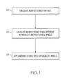
- Figure 1 is a flow chart of one example of a first method of the invention for providing stability control for a vehicle which calculates a modified desired yaw rate, which calculates a modified desired speed difference between the left and right wheels of the vehicle, and which applies the modified desired speed difference to the left and right wheels;
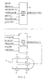
- Figure 2 is a block diagram showing a vehicle reference model having various inputs and having the modified desired yaw rate mentioned in figure 1 as an output and showing a vehicle control term calculator (modified desired speed difference calculator) having various inputs including the modified desired yaw rate and having the modified desired speed difference mentioned in figure 1 as an output;
- a vehicle control term calculator modified desired speed difference calculator
- FIG. 3 is a block diagram showing details of the vehicle reference model of figure 2 including an initial desired yaw rate calculator (labeled conventional calculations in figure 2 ), a yaw rate limit calculator, a tau damping value calculator, and a first order filter having the calculated tau damping value;
- Figure 4 is a block diagram showing details of the yaw rate limit calculator of figure 3 ;
- Figure 5 is a block diagram showing details of the tau damping value calculator of figure 3 ;
- Figure 6 is a block diagram showing details of the vehicle control term calculator of figure 2 including the calculation of an initial desired speed difference
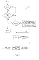
- Figure 7 is a flow chart of one example of a second method of the invention which calculates a modified desired yaw rate, which calculates an initial desired speed difference between the left and right wheels of the vehicle, and which applies the initial desired speed difference to the left and right wheels;
- Figure 8 is a flow chart of one example of a third method of the invention which calculates a filtered initial desired yaw rate, which calculates a modified desired speed difference between the left and right wheels of the vehicle, and which applies the modified desired speed difference to the left and right wheels.
- a first method of the invention is for providing stability control for a vehicle 10 having left and right wheels 12 & 14 and 16 & 18 and includes steps a) through c).
- Step a) is labeled as "Calculate Modified Desired Yaw Rate” in block 20 of figure 1 .
- Step a) includes calculating a modified desired yaw rate (see figure 2 ) for the vehicle using steer angle, steer angle rate, steer transition state, steer transition time, vehicle speed, lateral acceleration, and estimated surface friction (called “Surface Estimate” in the figures).
- Step b) is labeled as "Calculate Modified Desired Speed Difference Between Left And Right Vehicle Wheels" in block 22 of figure 1 .
- Step b) includes calculating a modified desired speed difference between the left and right wheels 12 & 14 and 16 & 18 (see figures 2 and 6 wherein such modified desired speed difference is called "Modified Delta Velocity" or "MDV") using the modified desired yaw rate, the steer angle rate, roll angle rate, the estimated surface friction, the vehicle speed, and sensed yaw rate.
- Step c) is labeled as "Apply Modified Desired Speed Difference To Wheels" in block 24 of figure 1 .
- Step c) includes applying the modified desired speed difference to the left and right wheels 12 & 14 and 16 & 18 (see figure 2 ).
- step a) uses a vehicle reference model 26 having steer angle, steer angle rate, steer transition state, steer transition time, vehicle speed, lateral acceleration, and estimated surface friction as inputs and having the modified desired yaw rate as an output (see figures 2 and 3 ).
- step b) uses a vehicle control term calculator 28 having the modified desired yaw rate, the steer angle rate, roll angle rate, the estimated surface friction, the vehicle speed, and sensed yaw rate as inputs and having the modified desired speed difference between the left and right wheels 12 & 14 and 16 & 18 (also called "Modified Delta Velocity" and "MDV”) as an output (see figures 2 and 6 ).
- step c) supplies the modified desired speed difference ("modified Delta Velocity” or "MDV") to a brake system controller 30 adapted to apply brake signals to individually brake each of the left and right wheels 12 & 14 and 16 & 18 to achieve the modified desired speed difference ("Modified Delta Velocity” or "MDV").
- modified Delta Velocity or "MDV”
- FIG 2 the un-labeled arrowed lines from the brake system controller 30 to the wheels 12, 14, 16 and 18 schematically represent such brake signals.
- input signals are filtered as appropriate to reduce noise.
- Steer transition state is a count of the number of times the driver reverses steering direction for a predetermined minimum steer angle reversal and a predetermined minimum steer angle reversal rate.
- Steer transition time is the time in one steer transition state.
- estimated surface friction (called “Surface Estimate” in the figures) has a value of 0.1 for a dry surface and 1.0 for ice.
- the remaining inputs e.g., angles, rates, speed and acceleration) are obtainable by those skilled in the art from a suitably instrumented vehicle.
- step a) includes calculating an initial desired yaw rate using the steer angle, the lateral acceleration, and the vehicle speed as is conventionally done in calculating a conventional desired yaw rate, such as by using conventional calculations (represented by block 32 of figure 3 ).
- step a) includes limiting the initial desired yaw rate based at least on the steer rate, such limiting of the initial desired yaw rate being represented by block 34 in figure 3 and shown in greater detail in figure 4 .
- Cl, C2, etc. represent predetermined constants which are obtained from previous vehicle testing and/or vehicle computer simulations for vehicle stability control as is within the ordinary level of skill of the artisan.
- the absolute value of the initial desired yaw rate is limited.
- the box labeled "Table Of Maximum Allowed Lateral Accelerations Based on Values Of Both Steer Angle Rate And Vehicle Speed” represents a table of values obtained from previous vehicle testing and/or vehicle computer simulations for vehicle stability control as is within the ordinary level of skill of the artisan.
- the box labeled "Convert To Maximum Allowed Yaw” represents a conversion that is within the ordinary level of skill of the artisan.
- STS is steer transition rate
- VS vehicle speed
- SAR steer angle rate
- MAL maximum allowed lateral acceleration
- LTY Lateral acceleration To Yaw rate conversion (such conversion being within the ordinary level of skill of the artisan). It is noted that C2 is less than Cl.
- step a) includes calculating a tau damping value of a first order filter 36 using the steer angle rate, the steer transition state, the steer transition time, the estimated surface friction, and the vehicle speed, such as by using a tau damping value calculator (represented by block 38 in figure 3 and shown in greater detail in figure 5 ).
- a tau damping value calculator represented by block 38 in figure 3 and shown in greater detail in figure 5 .
- the block labeled "Find Tau Based On Vehicle Speed” represents conventional calculations used for a first order filter for conventionally filtering a conventional desired yaw rate.
- the box labeled "Table Of Tau Values Based on Values Of Both Steer Angle Rate And Vehicle Speed” represents a table of tau values obtained from previous vehicle testing and/or vehicle computer simulations for vehicle stability control as is within the ordinary level of skill of the artisan.
- STS is steer transition rate
- VS vehicle speed
- SAR steer angle rate
- STT steer transition time
- SE surface estimate. It is noted that C6 is less than C5.
- step a) includes calculating the modified desired yaw rate by filtering the limited initial desired yaw rate using a first order filter 36 having the calculated tau damping value (see figure 3 ).
- step b) includes calculating a yaw rate error equal to the modified desired yaw rate minus the sensed yaw rate and includes calculating an initial desired speed difference between the left and right wheels equal to the calculated yaw rate error times a function of the estimated surface friction and the vehicle speed.
- yaw rate error and initial desired speed difference calculation is conventionally done in calculating a conventional desired yaw rate and a conventional desired speed difference.
- the function is expressed as a table.
- YRD is modified desired yaw rate
- SYR is sensed yaw rate
- YRE is yaw rate error
- IDV is initial delta velocity which is initial desired speed difference between the left and right vehicle wheels
- VS is vehicle speed
- SE is surface estimate (estimated surface friction)
- MDV is modified delta velocity which is modified desired speed difference between the left and right vehicle wheels
- RR is roll rate
- SAR is steer angle rate
- OS1 is a first offset to IDV
- OS2 is a second offset to IDV.
- step b) includes calculating the modified desired speed difference as equal to the initial desired speed difference plus a first offset which is a function of the roll angle rate and the vehicle speed plus a second offset which is a function of the steer angle rate and the vehicle speed.
- the functions are expressed as tables whose values have been obtained from previous vehicle testing and/or vehicle computer simulations for vehicle stability control as is within the ordinary level of skill of the artisan.
- a second method of the invention is for providing stability control for a vehicle 10 having left and right wheels 12 & 14 and 16 & 18.
- the second method includes steps a) through c).
- Step a) is labeled as "Calculate Modified Desired Yaw Rate” in block 40 of figure 7 .
- Step a) includes calculating a modified desired yaw rate for the vehicle using steer angle, steer angle rate, steer transition state, steer transition time, vehicle speed, lateral acceleration, and estimated surface friction.
- Step b) is labeled as "Calculate Initial Desired Speed Difference Between Left And Right Vehicle Wheels" in block 42 of figure 7 .
- Step b) includes calculating an initial desired speed difference between the left and right wheels using the modified desired yaw rate, the estimated surface friction, the vehicle speed, and sensed yaw rate.
- Step c) is labeled as "Apply Initial Desired Speed Difference To Wheels" in block 44 of figure 7 .
- Step c) includes applying the initial desired speed difference to the left and right wheels.
- step a) in the first method are equally applicable to step a) in the second method.
- a third method of the invention is for providing stability control for a vehicle 10 having left and right wheels 12 & 14 and 16 & 18.
- the third method includes steps a) through c).
- Step a) is labeled as "Calculate Filtered Initial Desired Yaw Rate” in block 46 of figure 8 .
- Step a) includes calculating a filtered initial desired yaw rate for the vehicle 10 using steer angle, vehicle speed, and lateral acceleration.
- Step b) is labeled as "Calculate Modified Desired Speed Difference Between Left And Right Vehicle Wheels" in block 48 of figure 8 .
- Step b) includes calculating a modified desired speed difference between the left and right wheels 12 & 14 and 16 & 18 using the filtered initial desired yaw rate, the steer angle rate, roll angle rate, the estimated surface friction, the vehicle speed, and sensed yaw rate.
- Step c) is labeled as "Apply Modified Desired Speed Difference To Wheels" in block 50 of figure 8 .
- Step c) includes applying the modified desired speed difference to the left and right wheels 12 & 14 and 16 & 18.
- step a) includes filtering the initial desired yaw rate using a first order filter having a tau damping value based on vehicle speed.
- the initial desired yaw rate is limited for some time after the event to reduce the yaw rate overshoot.
- damping of the desired yaw rate is increased to slow the response of the vehicle control to inputs from the driver for increased vehicle stability.
- the vehicle control term i.e., the desired speed difference
- the vehicle control term is offset by a function of the roll angle rate and the vehicle speed and is offset by a function of the steer angle rate and the vehicle speed for increased vehicle stability.
Landscapes
- Engineering & Computer Science (AREA)
- Transportation (AREA)
- Mechanical Engineering (AREA)
- Vehicle Body Suspensions (AREA)
- Steering Control In Accordance With Driving Conditions (AREA)
- Compounds Of Unknown Constitution (AREA)
- Control Of Driving Devices And Active Controlling Of Vehicle (AREA)
Abstract
calculating a modified desired yaw rate for the vehicle using steer angle, steer angle rate, steer transition state, steer transition time, vehicle speed, lateral acceleration, and estimated surface friction; calculating a modified desired speed difference between the left and right wheels using the modified desired yaw rate, the steer angle rate, roll angle rate, the estimated surface friction, the vehicle speed, and sensed yaw rate; and applying the modified desired speed difference to the left and right wheels. Another method calculates an initial desired speed difference between the left and right wheels using the modified desired yaw rate, the estimated surface friction, the vehicle speed, and sensed yaw rate. Another method calculates a filtered initial desired yaw rate for the vehicle using steer angle, vehicle speed, and lateral acceleration.
Description
- The present invention relates generally to vehicle control systems, and more particularly to a method for providing stability control for a vehicle.
- Conventional vehicle electronic control systems: calculate a desired yaw rate using steer angle, lateral acceleration and vehicle speed; filter the desired yaw rate using a first order filter having a tau damping value based on vehicle speed; calculate a desired speed difference between the left and right wheels using the filtered desired yaw rate, sensed yaw rate, estimated surface friction and vehicle speed; and apply the desired speed difference to the left and right wheels (by individualized four-wheel braking).
- What is needed is an improved method for providing stability control for a vehicle having left and right wheels.
- A first method of the invention is for providing stability control for a vehicle having left and right wheels and includes calculating a modified desired yaw rate for the vehicle using steer angle, steer angle rate, steer transition state, steer transition time, vehicle speed, lateral acceleration, and estimated surface friction. The first method also includes calculating a modified desired speed difference between the left and right wheels using the modified desired yaw rate, the steer angle rate, roll angle rate, the estimated surface friction, the vehicle speed, and sensed yaw rate. The first method also includes applying the modified desired speed difference to the left and right wheels.
- A second method of the invention is for providing stability control for a vehicle having left and right wheels. The second method includes calculating a modified desired yaw rate for the vehicle using steer angle, steer angle rate, steer transition state, steer transition time, vehicle speed, lateral acceleration, and estimated surface friction. The second method also includes calculating an initial desired speed difference between the left and right wheels using the modified desired yaw rate, the estimated surface friction, the vehicle speed, and sensed yaw rate. The second method also includes applying the initial desired speed difference to the left and right wheels.
- A third method of the invention is for providing stability control for a vehicle having left and right wheels. The third method includes calculating a filtered initial desired yaw rate for the vehicle using steer angle, vehicle speed, and lateral acceleration. The third method also includes calculating a modified desired speed difference between the left and right wheels using the filtered initial desired yaw rate, the steer angle rate, roll angle rate, the estimated surface friction, the vehicle speed, and sensed yaw rate. The third method also includes applying the modified desired speed difference to the left and right wheels.
- Several benefits and advantages are derived from one or more of the methods of the invention. In one example, after certain steering reversals by the driver with high steering angle rates, the initial desired yaw rate is limited for some time after the event to reduce the yaw rate overshoot. In the same or a different example, during certain maneuvers involving high steer angle rates, damping of the desired yaw rate is increased to slow the response of the vehicle control to inputs from the driver for increased vehicle stability. In the same or a different example, during certain maneuvers involving high roll angle rates and high steer angle rates, the vehicle control term (i.e., the desired speed difference) is offset by a function of the roll angle rate and the vehicle speed and is offset by a function of the steer angle rate and the vehicle speed for increased vehicle stability.
-
Figure 1 is a flow chart of one example of a first method of the invention for providing stability control for a vehicle which calculates a modified desired yaw rate, which calculates a modified desired speed difference between the left and right wheels of the vehicle, and which applies the modified desired speed difference to the left and right wheels; -
Figure 2 is a block diagram showing a vehicle reference model having various inputs and having the modified desired yaw rate mentioned infigure 1 as an output and showing a vehicle control term calculator (modified desired speed difference calculator) having various inputs including the modified desired yaw rate and having the modified desired speed difference mentioned infigure 1 as an output; -
Figure 3 is a block diagram showing details of the vehicle reference model offigure 2 including an initial desired yaw rate calculator (labeled conventional calculations infigure 2 ), a yaw rate limit calculator, a tau damping value calculator, and a first order filter having the calculated tau damping value; -
Figure 4 is a block diagram showing details of the yaw rate limit calculator offigure 3 ; -
Figure 5 is a block diagram showing details of the tau damping value calculator offigure 3 ; -
Figure 6 is a block diagram showing details of the vehicle control term calculator offigure 2 including the calculation of an initial desired speed difference; -
Figure 7 is a flow chart of one example of a second method of the invention which calculates a modified desired yaw rate, which calculates an initial desired speed difference between the left and right wheels of the vehicle, and which applies the initial desired speed difference to the left and right wheels; and -
Figure 8 is a flow chart of one example of a third method of the invention which calculates a filtered initial desired yaw rate, which calculates a modified desired speed difference between the left and right wheels of the vehicle, and which applies the modified desired speed difference to the left and right wheels. - Referring to
Figures 1 through 6 , a first method of the invention is for providing stability control for avehicle 10 having left andright wheels 12 & 14 and 16 & 18 and includes steps a) through c). Step a) is labeled as "Calculate Modified Desired Yaw Rate" inblock 20 offigure 1 . Step a) includes calculating a modified desired yaw rate (seefigure 2 ) for the vehicle using steer angle, steer angle rate, steer transition state, steer transition time, vehicle speed, lateral acceleration, and estimated surface friction (called "Surface Estimate" in the figures). Step b) is labeled as "Calculate Modified Desired Speed Difference Between Left And Right Vehicle Wheels" inblock 22 offigure 1 . Step b) includes calculating a modified desired speed difference between the left andright wheels 12 & 14 and 16 & 18 (seefigures 2 and6 wherein such modified desired speed difference is called "Modified Delta Velocity" or "MDV") using the modified desired yaw rate, the steer angle rate, roll angle rate, the estimated surface friction, the vehicle speed, and sensed yaw rate. Step c) is labeled as "Apply Modified Desired Speed Difference To Wheels" inblock 24 offigure 1 . Step c) includes applying the modified desired speed difference to the left andright wheels 12 & 14 and 16 & 18 (seefigure 2 ). - In one enablement of the first method, step a) uses a
vehicle reference model 26 having steer angle, steer angle rate, steer transition state, steer transition time, vehicle speed, lateral acceleration, and estimated surface friction as inputs and having the modified desired yaw rate as an output (seefigures 2 and3 ). In the same or a different enablement, step b) uses a vehiclecontrol term calculator 28 having the modified desired yaw rate, the steer angle rate, roll angle rate, the estimated surface friction, the vehicle speed, and sensed yaw rate as inputs and having the modified desired speed difference between the left andright wheels 12 & 14 and 16 & 18 (also called "Modified Delta Velocity" and "MDV") as an output (seefigures 2 and6 ). In the same or a different enablement, step c) supplies the modified desired speed difference ("modified Delta Velocity" or "MDV") to abrake system controller 30 adapted to apply brake signals to individually brake each of the left andright wheels 12 & 14 and 16 & 18 to achieve the modified desired speed difference ("Modified Delta Velocity" or "MDV"). Infigure 2 , the un-labeled arrowed lines from thebrake system controller 30 to thewheels - Steer transition state is a count of the number of times the driver reverses steering direction for a predetermined minimum steer angle reversal and a predetermined minimum steer angle reversal rate. Steer transition time is the time in one steer transition state. In one example, estimated surface friction (called "Surface Estimate" in the figures) has a value of 0.1 for a dry surface and 1.0 for ice. The remaining inputs (e.g., angles, rates, speed and acceleration) are obtainable by those skilled in the art from a suitably instrumented vehicle.
- In a first employment of the first method, step a) includes calculating an initial desired yaw rate using the steer angle, the lateral acceleration, and the vehicle speed as is conventionally done in calculating a conventional desired yaw rate, such as by using conventional calculations (represented by
block 32 offigure 3 ). - In one variation, step a) includes limiting the initial desired yaw rate based at least on the steer rate, such limiting of the initial desired yaw rate being represented by
block 34 infigure 3 and shown in greater detail infigure 4 . Infigure 4 (and in all other figures), Cl, C2, etc. represent predetermined constants which are obtained from previous vehicle testing and/or vehicle computer simulations for vehicle stability control as is within the ordinary level of skill of the artisan. The absolute value of the initial desired yaw rate is limited. The box labeled "Table Of Maximum Allowed Lateral Accelerations Based on Values Of Both Steer Angle Rate And Vehicle Speed" represents a table of values obtained from previous vehicle testing and/or vehicle computer simulations for vehicle stability control as is within the ordinary level of skill of the artisan. The box labeled "Convert To Maximum Allowed Yaw" represents a conversion that is within the ordinary level of skill of the artisan. - In
figure 4 , STS is steer transition rate, VS is vehicle speed, SAR is steer angle rate, MAL is maximum allowed lateral acceleration, and LTY is Lateral acceleration To Yaw rate conversion (such conversion being within the ordinary level of skill of the artisan). It is noted that C2 is less than Cl. - In one modification, step a) includes calculating a tau damping value of a
first order filter 36 using the steer angle rate, the steer transition state, the steer transition time, the estimated surface friction, and the vehicle speed, such as by using a tau damping value calculator (represented byblock 38 infigure 3 and shown in greater detail infigure 5 ). Infigure 5 , the block labeled "Find Tau Based On Vehicle Speed" represents conventional calculations used for a first order filter for conventionally filtering a conventional desired yaw rate. The box labeled "Table Of Tau Values Based on Values Of Both Steer Angle Rate And Vehicle Speed" represents a table of tau values obtained from previous vehicle testing and/or vehicle computer simulations for vehicle stability control as is within the ordinary level of skill of the artisan. - In
figure 5 , STS is steer transition rate, VS is vehicle speed, SAR is steer angle rate, STT is steer transition time, and SE is surface estimate. It is noted that C6 is less than C5. - In one illustration, step a) includes calculating the modified desired yaw rate by filtering the limited initial desired yaw rate using a
first order filter 36 having the calculated tau damping value (seefigure 3 ). - In the same or a different employment of the first method, and referring to
figure 6 , step b) includes calculating a yaw rate error equal to the modified desired yaw rate minus the sensed yaw rate and includes calculating an initial desired speed difference between the left and right wheels equal to the calculated yaw rate error times a function of the estimated surface friction and the vehicle speed. Such yaw rate error and initial desired speed difference calculation is conventionally done in calculating a conventional desired yaw rate and a conventional desired speed difference. In one example, the function is expressed as a table. - In
figure 6 , YRD is modified desired yaw rate, SYR is sensed yaw rate, YRE is yaw rate error, IDV is initial delta velocity which is initial desired speed difference between the left and right vehicle wheels, VS is vehicle speed, SE is surface estimate (estimated surface friction), MDV is modified delta velocity which is modified desired speed difference between the left and right vehicle wheels, RR is roll rate, SAR is steer angle rate, OS1 is a first offset to IDV, and OS2 is a second offset to IDV. - In one application, referring to
figure 6 , step b) includes calculating the modified desired speed difference as equal to the initial desired speed difference plus a first offset which is a function of the roll angle rate and the vehicle speed plus a second offset which is a function of the steer angle rate and the vehicle speed. In one example, the functions are expressed as tables whose values have been obtained from previous vehicle testing and/or vehicle computer simulations for vehicle stability control as is within the ordinary level of skill of the artisan. - Referring to
figure 7 and thevehicle 10 offigure 2 , a second method of the invention is for providing stability control for avehicle 10 having left andright wheels 12 & 14 and 16 & 18. The second method includes steps a) through c). Step a) is labeled as "Calculate Modified Desired Yaw Rate" inblock 40 offigure 7 . Step a) includes calculating a modified desired yaw rate for the vehicle using steer angle, steer angle rate, steer transition state, steer transition time, vehicle speed, lateral acceleration, and estimated surface friction. Step b) is labeled as "Calculate Initial Desired Speed Difference Between Left And Right Vehicle Wheels" inblock 42 offigure 7 . Step b) includes calculating an initial desired speed difference between the left and right wheels using the modified desired yaw rate, the estimated surface friction, the vehicle speed, and sensed yaw rate. Step c) is labeled as "Apply Initial Desired Speed Difference To Wheels" inblock 44 offigure 7 . Step c) includes applying the initial desired speed difference to the left and right wheels. - The employment, modification, etc. of step a) in the first method are equally applicable to step a) in the second method.
- Referring to
figure 8 and thevehicle 10 offigure 2 , a third method of the invention is for providing stability control for avehicle 10 having left andright wheels 12 & 14 and 16 & 18. The third method includes steps a) through c). Step a) is labeled as "Calculate Filtered Initial Desired Yaw Rate" inblock 46 offigure 8 . Step a) includes calculating a filtered initial desired yaw rate for thevehicle 10 using steer angle, vehicle speed, and lateral acceleration. Step b) is labeled as "Calculate Modified Desired Speed Difference Between Left And Right Vehicle Wheels" inblock 48 offigure 8 . Step b) includes calculating a modified desired speed difference between the left andright wheels 12 & 14 and 16 & 18 using the filtered initial desired yaw rate, the steer angle rate, roll angle rate, the estimated surface friction, the vehicle speed, and sensed yaw rate. Step c) is labeled as "Apply Modified Desired Speed Difference To Wheels" inblock 50 offigure 8 . Step c) includes applying the modified desired speed difference to the left andright wheels 12 & 14 and 16 & 18. - The employment and application of step b) and the employment of step a) in the first method are equally applicable to step b) and step a) in the third method. In one utilization of the third method, step a) includes filtering the initial desired yaw rate using a first order filter having a tau damping value based on vehicle speed.
- Several benefits and advantages are derived from one or more of the methods of the invention. In one example, after certain steering reversals by the driver with high steering angle rates, the initial desired yaw rate is limited for some time after the event to reduce the yaw rate overshoot. In the same or a different example, during certain maneuvers involving high steer angle rates, damping of the desired yaw rate is increased to slow the response of the vehicle control to inputs from the driver for increased vehicle stability. In the same or a different example, during certain maneuvers involving high roll angle rates and high steer angle rates, the vehicle control term (i.e., the desired speed difference) is offset by a function of the roll angle rate and the vehicle speed and is offset by a function of the steer angle rate and the vehicle speed for increased vehicle stability.
- The foregoing description of several methods of the invention has been presented for purposes of illustration. It is not intended to be exhaustive or to limit the invention to the precise steps disclosed, and obviously many modifications and variations are possible in light of the above teaching. It is intended that the scope of the invention be defined by the claims appended hereto.
Claims (20)
- A method for providing stability control for a vehicle having left and right wheels comprising:a) calculating a modified desired yaw rate for the vehicle using steer angle, steer angle rate, steer transition state, steer transition time, vehicle speed, lateral acceleration, and estimated surface friction;b) calculating a modified desired speed difference between the left and right wheels using the modified desired yaw rate, the steer angle rate, roll angle rate, the estimated surface friction, the vehicle speed, and sensed yaw rate; andc) applying the modified desired speed difference to the left and right wheels.
- The method of claim 1, wherein step a) includes calculating an initial desired yaw rate using the steer angle, the lateral acceleration, and the vehicle speed.
- The method of claim 2, wherein step a) includes limiting the initial desired yaw rate based at least on the steer rate.
- The method of claim 3, wherein step a) includes calculating a tau damping value of a first order filter using the steer angle rate, the steer transition state, the steer transition time, the estimated surface friction, and the vehicle speed.
- The method of claim 4, wherein step a) includes calculating the modified desired yaw rate by filtering the limited initial desired yaw rate using a first order filter having the calculated tau damping valve.
- The method of claim 5, wherein step b) includes calculating a yaw rate error equal to the modified desired yaw rate minus the sensed yaw rate and calculating an initial desired speed difference between the left and right wheels equal to the calculated yaw rate error times a function of the estimated surface friction and the vehicle speed.
- The method of claim 6, wherein step b) includes calculating the modified desired speed difference as equal to the initial desired speed difference plus a function of the roll angle rate and the vehicle speed plus a function of the steer angle rate and the vehicle speed.
- The method of claim 1, wherein step b) includes calculating a yaw rate error equal to the modified desired yaw rate minus the sensed yaw rate and calculating an initial desired speed difference between the left and right wheels equal to the calculated yaw rate error times a function of the estimated surface friction and the vehicle speed.
- The method of claim 8, wherein step b) includes calculating the modified desired speed difference as equal to the initial desired speed difference plus a function of the roll angle rate and the vehicle speed plus a function of the steer angle rate and the vehicle speed.
- A method for providing stability control for a vehicle having left and right wheels comprising:a) calculating a modified desired yaw rate for the vehicle using steer angle, steer angle rate, steer transition state, steer transition time, vehicle speed, lateral acceleration, and estimated surface friction;b) calculating an initial desired speed difference between the left and right wheels using the modified desired yaw rate, the estimated surface friction, the vehicle speed, and sensed yaw rate; andc) applying the initial desired speed difference to the left and right wheels.
- The method of claim 10, wherein step a) includes calculating an initial desired yaw rate using the steer angle, the lateral acceleration, and the vehicle speed.
- The method of claim 11, wherein step a) includes limiting the initial desired yaw rate based at least on the steer rate.
- The method of claim 12, wherein step a) includes calculating a tau damping value of a first order filter using the steer angle rate, the steer transition state, the steer transition time, the estimated surface friction, and the vehicle speed.
- The method of claim 13, wherein step a) includes calculating the modified desired yaw rate by filtering the limited initial desired yaw rate using a first order filter having the calculated tau damping valve.
- A method for providing stability control for a vehicle having left and right wheels comprising:a) calculating a filtered initial desired yaw rate for the vehicle using steer angle, vehicle speed, and lateral acceleration;b) calculating a modified desired speed difference between the left and right wheels using the filtered initial desired yaw rate, the steer angle rate, roll angle rate, the estimated surface friction, the vehicle speed, and sensed yaw rate; andc) applying the modified desired speed difference to the left and right wheels.
- The method of claim 15, wherein step b) includes calculating a yaw rate error equal to the modified desired yaw rate minus the sensed yaw rate and calculating an initial desired speed difference between the left and right wheels equal to the calculated yaw rate error times a function of the estimated surface friction and the vehicle speed.
- The method of claim 16, wherein step b) includes calculating the modified desired speed difference as equal to the initial desired speed difference plus a function of the roll angle rate and the vehicle speed plus a function of the steer angle rate and the vehicle speed.
- The method of claim 17, wherein step a) includes calculating an initial desired yaw rate using the steer angle, the lateral acceleration, and the vehicle speed.
- The method of claim 18, wherein step a) includes filtering the initial desired yaw rate using a first order filter having a tau damping value based on vehicle speed.
- The method of claim 15, wherein step a) includes filtering the initial desired yaw rate using a first order filter having a tau damping value based on vehicle speed.
Applications Claiming Priority (1)
| Application Number | Priority Date | Filing Date | Title |
|---|---|---|---|
| US11/636,002 US20080140264A1 (en) | 2006-12-08 | 2006-12-08 | Method for providing stability control for a vehicle |
Publications (2)
| Publication Number | Publication Date |
|---|---|
| EP1930222A1 true EP1930222A1 (en) | 2008-06-11 |
| EP1930222B1 EP1930222B1 (en) | 2010-01-20 |
Family
ID=39111572
Family Applications (1)
| Application Number | Title | Priority Date | Filing Date |
|---|---|---|---|
| EP07121160A Not-in-force EP1930222B1 (en) | 2006-12-08 | 2007-11-20 | Method for providing stability control for a vehicle |
Country Status (4)
| Country | Link |
|---|---|
| US (1) | US20080140264A1 (en) |
| EP (1) | EP1930222B1 (en) |
| AT (1) | ATE455688T1 (en) |
| DE (1) | DE602007004418D1 (en) |
Cited By (2)
| Publication number | Priority date | Publication date | Assignee | Title |
|---|---|---|---|---|
| GB2477341A (en) * | 2010-02-01 | 2011-08-03 | Gm Global Tech Operations Inc | A method of estimating a cornering limit of a vehicle |
| DE102017010427A1 (en) * | 2017-11-10 | 2019-05-16 | Roland Kolbeck | Steering system for movable driven devices |
Families Citing this family (5)
| Publication number | Priority date | Publication date | Assignee | Title |
|---|---|---|---|---|
| DE102016204018A1 (en) * | 2016-03-11 | 2017-09-14 | Robert Bosch Gmbh | Method and device for determining the bank of a road |
| US10300897B2 (en) * | 2017-05-15 | 2019-05-28 | Goodrich Corporation | Brake load balance and runway centering techniques |
| KR102418028B1 (en) | 2018-04-06 | 2022-07-06 | 현대자동차주식회사 | Vehicle control system, and controlling method thereof |
| JP7193784B2 (en) * | 2020-03-09 | 2022-12-21 | トヨタ自動車株式会社 | vehicle controller |
| CN114404235B (en) * | 2022-01-26 | 2024-03-19 | 浙江益恒悦医疗科技有限公司 | Steering assist control method, steering assist control device and memory of walking aid |
Citations (7)
| Publication number | Priority date | Publication date | Assignee | Title |
|---|---|---|---|---|
| EP0958978A2 (en) * | 1998-05-18 | 1999-11-24 | General Motors Corporation | Vehicle yaw control method |
| US6179394B1 (en) * | 1998-11-09 | 2001-01-30 | General Motors Corporation | Active brake balance control method |
| US6453226B1 (en) | 2001-01-25 | 2002-09-17 | Delphi Technologies, Inc. | Integrated control of active tire steer and brakes |
| US20020153770A1 (en) * | 2001-04-24 | 2002-10-24 | Fuji Jukogyo Kabushiki Kaisha | Vehicle behavior control apparatus |
| US20050012391A1 (en) * | 2003-07-17 | 2005-01-20 | Toshihisa Kato | Vehicle motion control apparatus |
| EP1640231A1 (en) * | 2004-09-27 | 2006-03-29 | Delphi Technologies, Inc. | Motor vehicle control using a dynamic feedforward approach |
| WO2006129820A1 (en) * | 2005-06-01 | 2006-12-07 | Toyota Jidosha Kabushiki Kaisha | Vehicle braking/driving force control apparatus |
Family Cites Families (9)
| Publication number | Priority date | Publication date | Assignee | Title |
|---|---|---|---|---|
| US3654599A (en) * | 1970-04-10 | 1972-04-04 | Life Technology Inc | Vehicle steering reversal rate alarm system |
| JPS5916969B2 (en) * | 1975-02-07 | 1984-04-18 | 日産自動車株式会社 | Automotive safety equipment |
| JPS59153624A (en) * | 1983-02-18 | 1984-09-01 | Nissan Motor Co Ltd | Dozing-drive detecting apparatus |
| JP4263448B2 (en) * | 2002-09-24 | 2009-05-13 | 富士重工業株式会社 | Vehicle differential limiting control device |
| US7165644B2 (en) * | 2004-03-18 | 2007-01-23 | Ford Global Technologies, Llc | Method and apparatus of controlling an automotive vehicle using brake-steer as a function of steering wheel torque |
| US8380416B2 (en) * | 2004-03-18 | 2013-02-19 | Ford Global Technologies | Method and apparatus for controlling brake-steer in an automotive vehicle in reverse |
| US6959970B2 (en) * | 2004-03-18 | 2005-11-01 | Ford Global Technologies, Llc | Method and apparatus for controlling a trailer and an automotive vehicle with a yaw stability control system |
| US7401870B2 (en) * | 2004-03-18 | 2008-07-22 | Ford Global Technologies, Llc | Method and apparatus to enhance brake-steer of a vehicle using a controllable suspension component |
| JP4391304B2 (en) * | 2004-04-23 | 2009-12-24 | 日産自動車株式会社 | Deceleration control device |
-
2006
- 2006-12-08 US US11/636,002 patent/US20080140264A1/en not_active Abandoned
-
2007
- 2007-11-20 DE DE602007004418T patent/DE602007004418D1/en active Active
- 2007-11-20 AT AT07121160T patent/ATE455688T1/en not_active IP Right Cessation
- 2007-11-20 EP EP07121160A patent/EP1930222B1/en not_active Not-in-force
Patent Citations (7)
| Publication number | Priority date | Publication date | Assignee | Title |
|---|---|---|---|---|
| EP0958978A2 (en) * | 1998-05-18 | 1999-11-24 | General Motors Corporation | Vehicle yaw control method |
| US6179394B1 (en) * | 1998-11-09 | 2001-01-30 | General Motors Corporation | Active brake balance control method |
| US6453226B1 (en) | 2001-01-25 | 2002-09-17 | Delphi Technologies, Inc. | Integrated control of active tire steer and brakes |
| US20020153770A1 (en) * | 2001-04-24 | 2002-10-24 | Fuji Jukogyo Kabushiki Kaisha | Vehicle behavior control apparatus |
| US20050012391A1 (en) * | 2003-07-17 | 2005-01-20 | Toshihisa Kato | Vehicle motion control apparatus |
| EP1640231A1 (en) * | 2004-09-27 | 2006-03-29 | Delphi Technologies, Inc. | Motor vehicle control using a dynamic feedforward approach |
| WO2006129820A1 (en) * | 2005-06-01 | 2006-12-07 | Toyota Jidosha Kabushiki Kaisha | Vehicle braking/driving force control apparatus |
Cited By (2)
| Publication number | Priority date | Publication date | Assignee | Title |
|---|---|---|---|---|
| GB2477341A (en) * | 2010-02-01 | 2011-08-03 | Gm Global Tech Operations Inc | A method of estimating a cornering limit of a vehicle |
| DE102017010427A1 (en) * | 2017-11-10 | 2019-05-16 | Roland Kolbeck | Steering system for movable driven devices |
Also Published As
| Publication number | Publication date |
|---|---|
| ATE455688T1 (en) | 2010-02-15 |
| DE602007004418D1 (en) | 2010-03-11 |
| EP1930222B1 (en) | 2010-01-20 |
| US20080140264A1 (en) | 2008-06-12 |
Similar Documents
| Publication | Publication Date | Title |
|---|---|---|
| EP1930222B1 (en) | Method for providing stability control for a vehicle | |
| US6549842B1 (en) | Method and apparatus for determining an individual wheel surface coefficient of adhesion | |
| US8326504B2 (en) | Holistic control for stabilizing vehicle-trailer swaying | |
| US6804594B1 (en) | Active steering for handling/stability enhancement | |
| JP6754433B2 (en) | Systems and methods for independently controlling wheel slip and vehicle acceleration | |
| US9643607B2 (en) | Vehicle motion control system | |
| JP6663072B1 (en) | Steering determination device, steering control device, and steering device | |
| US9878738B2 (en) | Non-linear compensation controller for active steering system in a vehicle | |
| US5402345A (en) | Method for estimating speed of a braked vehicle | |
| KR100374093B1 (en) | Vehicle movement characteristic control system | |
| US11945430B2 (en) | Vehicle motion control system | |
| JP2019111987A (en) | Control unit and steering device | |
| CN114728672A (en) | Steering hold determination device, steering control device, and steering device | |
| JP4069481B2 (en) | Vehicle behavior estimation device | |
| WO2003022651A1 (en) | Advanced wheel slip detection using suspension system information | |
| US6964460B2 (en) | Brake controller and method for controlling a brake system | |
| CN114407848A (en) | A brake control method, device, electronic device and storage medium | |
| EP4663500A1 (en) | Chassis integrated control system and method, and device, medium and program product | |
| US8500219B2 (en) | Method and device for stabilizing a vehicle | |
| CN117382635A (en) | Vehicle anti-skid control method, system, vehicle and storage medium | |
| EP2371586A1 (en) | Method for controlling the fluidic actuation of a brake or suspension system | |
| EP2208651B1 (en) | Acceleration vector controlled vehicle cornering stability system | |
| CN115195681A (en) | Anti-lock control method and system for vehicle and vehicle | |
| KR101585268B1 (en) | method for calculation yaw-rate in ABS control | |
| DE102021205561A1 (en) | Method and system for controlling a vehicle |
Legal Events
| Date | Code | Title | Description |
|---|---|---|---|
| PUAI | Public reference made under article 153(3) epc to a published international application that has entered the european phase |
Free format text: ORIGINAL CODE: 0009012 |
|
| AK | Designated contracting states |
Kind code of ref document: A1 Designated state(s): AT BE BG CH CY CZ DE DK EE ES FI FR GB GR HU IE IS IT LI LT LU LV MC MT NL PL PT RO SE SI SK TR |
|
| AX | Request for extension of the european patent |
Extension state: AL BA HR MK RS |
|
| 17P | Request for examination filed |
Effective date: 20081211 |
|
| 17Q | First examination report despatched |
Effective date: 20090113 |
|
| AKX | Designation fees paid |
Designated state(s): AT BE BG CH CY CZ DE DK EE ES FI FR GB GR HU IE IS IT LI LT LU LV MC MT NL PL PT RO SE SI SK TR |
|
| GRAP | Despatch of communication of intention to grant a patent |
Free format text: ORIGINAL CODE: EPIDOSNIGR1 |
|
| GRAS | Grant fee paid |
Free format text: ORIGINAL CODE: EPIDOSNIGR3 |
|
| GRAA | (expected) grant |
Free format text: ORIGINAL CODE: 0009210 |
|
| AK | Designated contracting states |
Kind code of ref document: B1 Designated state(s): AT BE BG CH CY CZ DE DK EE ES FI FR GB GR HU IE IS IT LI LT LU LV MC MT NL PL PT RO SE SI SK TR |
|
| REG | Reference to a national code |
Ref country code: GB Ref legal event code: FG4D |
|
| REG | Reference to a national code |
Ref country code: CH Ref legal event code: EP |
|
| REG | Reference to a national code |
Ref country code: IE Ref legal event code: FG4D |
|
| REF | Corresponds to: |
Ref document number: 602007004418 Country of ref document: DE Date of ref document: 20100311 Kind code of ref document: P |
|
| REG | Reference to a national code |
Ref country code: NL Ref legal event code: VDEP Effective date: 20100120 |
|
| LTIE | Lt: invalidation of european patent or patent extension |
Effective date: 20100120 |
|
| PG25 | Lapsed in a contracting state [announced via postgrant information from national office to epo] |
Ref country code: AT Free format text: LAPSE BECAUSE OF FAILURE TO SUBMIT A TRANSLATION OF THE DESCRIPTION OR TO PAY THE FEE WITHIN THE PRESCRIBED TIME-LIMIT Effective date: 20100120 |
|
| PG25 | Lapsed in a contracting state [announced via postgrant information from national office to epo] |
Ref country code: NL Free format text: LAPSE BECAUSE OF FAILURE TO SUBMIT A TRANSLATION OF THE DESCRIPTION OR TO PAY THE FEE WITHIN THE PRESCRIBED TIME-LIMIT Effective date: 20100120 Ref country code: LT Free format text: LAPSE BECAUSE OF FAILURE TO SUBMIT A TRANSLATION OF THE DESCRIPTION OR TO PAY THE FEE WITHIN THE PRESCRIBED TIME-LIMIT Effective date: 20100120 Ref country code: IS Free format text: LAPSE BECAUSE OF FAILURE TO SUBMIT A TRANSLATION OF THE DESCRIPTION OR TO PAY THE FEE WITHIN THE PRESCRIBED TIME-LIMIT Effective date: 20100520 Ref country code: ES Free format text: LAPSE BECAUSE OF FAILURE TO SUBMIT A TRANSLATION OF THE DESCRIPTION OR TO PAY THE FEE WITHIN THE PRESCRIBED TIME-LIMIT Effective date: 20100501 Ref country code: PT Free format text: LAPSE BECAUSE OF FAILURE TO SUBMIT A TRANSLATION OF THE DESCRIPTION OR TO PAY THE FEE WITHIN THE PRESCRIBED TIME-LIMIT Effective date: 20100520 |
|
| PG25 | Lapsed in a contracting state [announced via postgrant information from national office to epo] |
Ref country code: PL Free format text: LAPSE BECAUSE OF FAILURE TO SUBMIT A TRANSLATION OF THE DESCRIPTION OR TO PAY THE FEE WITHIN THE PRESCRIBED TIME-LIMIT Effective date: 20100120 Ref country code: LV Free format text: LAPSE BECAUSE OF FAILURE TO SUBMIT A TRANSLATION OF THE DESCRIPTION OR TO PAY THE FEE WITHIN THE PRESCRIBED TIME-LIMIT Effective date: 20100120 Ref country code: FI Free format text: LAPSE BECAUSE OF FAILURE TO SUBMIT A TRANSLATION OF THE DESCRIPTION OR TO PAY THE FEE WITHIN THE PRESCRIBED TIME-LIMIT Effective date: 20100120 Ref country code: SI Free format text: LAPSE BECAUSE OF FAILURE TO SUBMIT A TRANSLATION OF THE DESCRIPTION OR TO PAY THE FEE WITHIN THE PRESCRIBED TIME-LIMIT Effective date: 20100120 |
|
| PG25 | Lapsed in a contracting state [announced via postgrant information from national office to epo] |
Ref country code: RO Free format text: LAPSE BECAUSE OF FAILURE TO SUBMIT A TRANSLATION OF THE DESCRIPTION OR TO PAY THE FEE WITHIN THE PRESCRIBED TIME-LIMIT Effective date: 20100120 Ref country code: GR Free format text: LAPSE BECAUSE OF FAILURE TO SUBMIT A TRANSLATION OF THE DESCRIPTION OR TO PAY THE FEE WITHIN THE PRESCRIBED TIME-LIMIT Effective date: 20100421 Ref country code: BE Free format text: LAPSE BECAUSE OF FAILURE TO SUBMIT A TRANSLATION OF THE DESCRIPTION OR TO PAY THE FEE WITHIN THE PRESCRIBED TIME-LIMIT Effective date: 20100120 Ref country code: SE Free format text: LAPSE BECAUSE OF FAILURE TO SUBMIT A TRANSLATION OF THE DESCRIPTION OR TO PAY THE FEE WITHIN THE PRESCRIBED TIME-LIMIT Effective date: 20100120 Ref country code: CY Free format text: LAPSE BECAUSE OF FAILURE TO SUBMIT A TRANSLATION OF THE DESCRIPTION OR TO PAY THE FEE WITHIN THE PRESCRIBED TIME-LIMIT Effective date: 20100120 Ref country code: EE Free format text: LAPSE BECAUSE OF FAILURE TO SUBMIT A TRANSLATION OF THE DESCRIPTION OR TO PAY THE FEE WITHIN THE PRESCRIBED TIME-LIMIT Effective date: 20100120 |
|
| PLBE | No opposition filed within time limit |
Free format text: ORIGINAL CODE: 0009261 |
|
| STAA | Information on the status of an ep patent application or granted ep patent |
Free format text: STATUS: NO OPPOSITION FILED WITHIN TIME LIMIT |
|
| PG25 | Lapsed in a contracting state [announced via postgrant information from national office to epo] |
Ref country code: BG Free format text: LAPSE BECAUSE OF FAILURE TO SUBMIT A TRANSLATION OF THE DESCRIPTION OR TO PAY THE FEE WITHIN THE PRESCRIBED TIME-LIMIT Effective date: 20100420 Ref country code: SK Free format text: LAPSE BECAUSE OF FAILURE TO SUBMIT A TRANSLATION OF THE DESCRIPTION OR TO PAY THE FEE WITHIN THE PRESCRIBED TIME-LIMIT Effective date: 20100120 Ref country code: CZ Free format text: LAPSE BECAUSE OF FAILURE TO SUBMIT A TRANSLATION OF THE DESCRIPTION OR TO PAY THE FEE WITHIN THE PRESCRIBED TIME-LIMIT Effective date: 20100120 |
|
| 26N | No opposition filed |
Effective date: 20101021 |
|
| PG25 | Lapsed in a contracting state [announced via postgrant information from national office to epo] |
Ref country code: DK Free format text: LAPSE BECAUSE OF FAILURE TO SUBMIT A TRANSLATION OF THE DESCRIPTION OR TO PAY THE FEE WITHIN THE PRESCRIBED TIME-LIMIT Effective date: 20100120 |
|
| PG25 | Lapsed in a contracting state [announced via postgrant information from national office to epo] |
Ref country code: IT Free format text: LAPSE BECAUSE OF FAILURE TO SUBMIT A TRANSLATION OF THE DESCRIPTION OR TO PAY THE FEE WITHIN THE PRESCRIBED TIME-LIMIT Effective date: 20100120 |
|
| PG25 | Lapsed in a contracting state [announced via postgrant information from national office to epo] |
Ref country code: MC Free format text: LAPSE BECAUSE OF NON-PAYMENT OF DUE FEES Effective date: 20101130 |
|
| PG25 | Lapsed in a contracting state [announced via postgrant information from national office to epo] |
Ref country code: IE Free format text: LAPSE BECAUSE OF NON-PAYMENT OF DUE FEES Effective date: 20101120 |
|
| PG25 | Lapsed in a contracting state [announced via postgrant information from national office to epo] |
Ref country code: MT Free format text: LAPSE BECAUSE OF FAILURE TO SUBMIT A TRANSLATION OF THE DESCRIPTION OR TO PAY THE FEE WITHIN THE PRESCRIBED TIME-LIMIT Effective date: 20100120 |
|
| REG | Reference to a national code |
Ref country code: CH Ref legal event code: PL |
|
| PG25 | Lapsed in a contracting state [announced via postgrant information from national office to epo] |
Ref country code: CH Free format text: LAPSE BECAUSE OF NON-PAYMENT OF DUE FEES Effective date: 20111130 Ref country code: LI Free format text: LAPSE BECAUSE OF NON-PAYMENT OF DUE FEES Effective date: 20111130 |
|
| PG25 | Lapsed in a contracting state [announced via postgrant information from national office to epo] |
Ref country code: HU Free format text: LAPSE BECAUSE OF FAILURE TO SUBMIT A TRANSLATION OF THE DESCRIPTION OR TO PAY THE FEE WITHIN THE PRESCRIBED TIME-LIMIT Effective date: 20100721 Ref country code: LU Free format text: LAPSE BECAUSE OF NON-PAYMENT OF DUE FEES Effective date: 20101120 |
|
| PG25 | Lapsed in a contracting state [announced via postgrant information from national office to epo] |
Ref country code: TR Free format text: LAPSE BECAUSE OF FAILURE TO SUBMIT A TRANSLATION OF THE DESCRIPTION OR TO PAY THE FEE WITHIN THE PRESCRIBED TIME-LIMIT Effective date: 20100120 |
|
| PGFP | Annual fee paid to national office [announced via postgrant information from national office to epo] |
Ref country code: FR Payment date: 20131108 Year of fee payment: 7 Ref country code: DE Payment date: 20131113 Year of fee payment: 7 Ref country code: GB Payment date: 20131120 Year of fee payment: 7 |
|
| REG | Reference to a national code |
Ref country code: DE Ref legal event code: R119 Ref document number: 602007004418 Country of ref document: DE |
|
| GBPC | Gb: european patent ceased through non-payment of renewal fee |
Effective date: 20141120 |
|
| REG | Reference to a national code |
Ref country code: FR Ref legal event code: ST Effective date: 20150731 |
|
| PG25 | Lapsed in a contracting state [announced via postgrant information from national office to epo] |
Ref country code: DE Free format text: LAPSE BECAUSE OF NON-PAYMENT OF DUE FEES Effective date: 20150602 Ref country code: GB Free format text: LAPSE BECAUSE OF NON-PAYMENT OF DUE FEES Effective date: 20141120 |
|
| PG25 | Lapsed in a contracting state [announced via postgrant information from national office to epo] |
Ref country code: FR Free format text: LAPSE BECAUSE OF NON-PAYMENT OF DUE FEES Effective date: 20141201 |
|
| REG | Reference to a national code |
Ref country code: GB Ref legal event code: 732E Free format text: REGISTERED BETWEEN 20170727 AND 20170802 |
|
| REG | Reference to a national code |
Ref country code: DE Ref legal event code: R081 Ref document number: 602007004418 Country of ref document: DE Owner name: BWI COMPANY LIMITED S.A., LU Free format text: FORMER OWNER: DELPHI TECHNOLOGIES INC., TROY, MICH., US Ref country code: DE Ref legal event code: R082 Ref document number: 602007004418 Country of ref document: DE |