EP1930127A1 - Bearing of a breaking device tool - Google Patents
Bearing of a breaking device tool Download PDFInfo
- Publication number
- EP1930127A1 EP1930127A1 EP07121945A EP07121945A EP1930127A1 EP 1930127 A1 EP1930127 A1 EP 1930127A1 EP 07121945 A EP07121945 A EP 07121945A EP 07121945 A EP07121945 A EP 07121945A EP 1930127 A1 EP1930127 A1 EP 1930127A1
- Authority
- EP
- European Patent Office
- Prior art keywords
- bearing
- bushing
- tool
- frame
- breaking device
- Prior art date
- Legal status (The legal status is an assumption and is not a legal conclusion. Google has not performed a legal analysis and makes no representation as to the accuracy of the status listed.)
- Granted
Links
- 239000000463 material Substances 0.000 claims abstract description 42
- 238000009527 percussion Methods 0.000 claims abstract description 33
- 230000006835 compression Effects 0.000 claims abstract description 20
- 238000007906 compression Methods 0.000 claims abstract description 20
- 238000000034 method Methods 0.000 claims abstract description 11
- 239000011435 rock Substances 0.000 claims description 14
- 238000005553 drilling Methods 0.000 claims description 13
- 239000004033 plastic Substances 0.000 claims description 9
- 230000000694 effects Effects 0.000 claims description 7
- 229910000906 Bronze Inorganic materials 0.000 claims description 5
- 239000010974 bronze Substances 0.000 claims description 5
- KUNSUQLRTQLHQQ-UHFFFAOYSA-N copper tin Chemical compound [Cu].[Sn] KUNSUQLRTQLHQQ-UHFFFAOYSA-N 0.000 claims description 5
- 239000000314 lubricant Substances 0.000 description 6
- 238000004519 manufacturing process Methods 0.000 description 4
- 229910000897 Babbitt (metal) Inorganic materials 0.000 description 2
- 229910000831 Steel Inorganic materials 0.000 description 2
- 230000001133 acceleration Effects 0.000 description 2
- 238000003825 pressing Methods 0.000 description 2
- 239000010959 steel Substances 0.000 description 2
- 229910000838 Al alloy Inorganic materials 0.000 description 1
- OKTJSMMVPCPJKN-UHFFFAOYSA-N Carbon Chemical compound [C] OKTJSMMVPCPJKN-UHFFFAOYSA-N 0.000 description 1
- 239000004760 aramid Substances 0.000 description 1
- 229920003235 aromatic polyamide Polymers 0.000 description 1
- 239000011324 bead Substances 0.000 description 1
- 229910052799 carbon Inorganic materials 0.000 description 1
- 239000000835 fiber Substances 0.000 description 1
- 239000003365 glass fiber Substances 0.000 description 1
- 239000012535 impurity Substances 0.000 description 1
- 239000002184 metal Substances 0.000 description 1
- 229910052751 metal Inorganic materials 0.000 description 1
- 230000001681 protective effect Effects 0.000 description 1
- 239000002990 reinforced plastic Substances 0.000 description 1
- 238000003466 welding Methods 0.000 description 1
Images



Classifications
-
- E—FIXED CONSTRUCTIONS
- E02—HYDRAULIC ENGINEERING; FOUNDATIONS; SOIL SHIFTING
- E02F—DREDGING; SOIL-SHIFTING
- E02F3/00—Dredgers; Soil-shifting machines
- E02F3/04—Dredgers; Soil-shifting machines mechanically-driven
- E02F3/28—Dredgers; Soil-shifting machines mechanically-driven with digging tools mounted on a dipper- or bucket-arm, i.e. there is either one arm or a pair of arms, e.g. dippers, buckets
- E02F3/36—Component parts
-
- B—PERFORMING OPERATIONS; TRANSPORTING
- B25—HAND TOOLS; PORTABLE POWER-DRIVEN TOOLS; MANIPULATORS
- B25D—PERCUSSIVE TOOLS
- B25D17/00—Details of, or accessories for, portable power-driven percussive tools
- B25D17/08—Means for retaining and guiding the tool bit, e.g. chucks allowing axial oscillation of the tool bit
-
- E—FIXED CONSTRUCTIONS
- E02—HYDRAULIC ENGINEERING; FOUNDATIONS; SOIL SHIFTING
- E02F—DREDGING; SOIL-SHIFTING
- E02F5/00—Dredgers or soil-shifting machines for special purposes
- E02F5/16—Machines for digging other holes in the soil
-
- B—PERFORMING OPERATIONS; TRANSPORTING
- B25—HAND TOOLS; PORTABLE POWER-DRIVEN TOOLS; MANIPULATORS
- B25D—PERCUSSIVE TOOLS
- B25D2222/00—Materials of the tool or the workpiece
- B25D2222/21—Metals
- B25D2222/31—Bronze
-
- B—PERFORMING OPERATIONS; TRANSPORTING
- B25—HAND TOOLS; PORTABLE POWER-DRIVEN TOOLS; MANIPULATORS
- B25D—PERCUSSIVE TOOLS
- B25D2222/00—Materials of the tool or the workpiece
- B25D2222/54—Plastics
-
- B—PERFORMING OPERATIONS; TRANSPORTING
- B25—HAND TOOLS; PORTABLE POWER-DRIVEN TOOLS; MANIPULATORS
- B25D—PERCUSSIVE TOOLS
- B25D2250/00—General details of portable percussive tools; Components used in portable percussive tools
- B25D2250/331—Use of bearings
-
- Y—GENERAL TAGGING OF NEW TECHNOLOGICAL DEVELOPMENTS; GENERAL TAGGING OF CROSS-SECTIONAL TECHNOLOGIES SPANNING OVER SEVERAL SECTIONS OF THE IPC; TECHNICAL SUBJECTS COVERED BY FORMER USPC CROSS-REFERENCE ART COLLECTIONS [XRACs] AND DIGESTS
- Y10—TECHNICAL SUBJECTS COVERED BY FORMER USPC
- Y10T—TECHNICAL SUBJECTS COVERED BY FORMER US CLASSIFICATION
- Y10T29/00—Metal working
- Y10T29/49—Method of mechanical manufacture
- Y10T29/49826—Assembling or joining
Definitions
- the invention relates to a method for fitting a breaking device tool with a bearing, a breaking device and a tool bushing used for a bearing.
- the breaking device comprises at least a frame, a tool and a percussion device.
- a percussion element in the percussion device By means of a percussion element in the percussion device, compression stress pulses are generated in the tool, which transmits them further to material to be broken.
- a bearing bushing is arranged, a sliding surface on the inner periphery of the bearing bushing fitting the tool with a bearing to be movable in the axial direction of the tool.
- a breaking hammer is a breaking device used as a supplementary device of an excavator or another basic machine when the intention is to break for instance rock, concrete or other relatively hard material.
- the percussion device of the breaking hammer is used to give compression stress pulses to a tool attached to the breaking hammer, the tool transmitting the stress pulses to the material to be broken.
- the tool is pressed against the material to be broken, whereby the effect of the stress waves and pressing causes the tool to penetrate into the material to be broken, which results in breaking of the material.
- the tool of the breaking device is mounted on a bearing in the frame of the breaking device in such a way that it can move in the axial direction during the breaking.
- the tool is usually mounted on a slide bearing by means of one or more bearing bushings.
- the bearing bushing is attached to a tool bushing that is, in turn, attached to the frame of the breaking device.
- the bearing bushing is a slide bearing that wears in use, due to which it has to be changed from time to time.
- a problem with known solutions is that it is difficult and slow to change a worn bearing bushing in working site conditions.
- An object of this invention is to provide a novel and an improved method for fitting a breaking device tool with a bearing, a breaking device and a tool bushing.
- the method according to the invention is characterized by arranging a clearance fit between the outer diameter of the bearing bushing and the diameter of the bearing space; inserting the bearing bushing in the axial direction to its place in the bearing space without a force effect resulting from the reciprocal dimensioning of the diameters of the bearing bushing and the bearing space; and locking the bearing bushing during the use of the breaking device in the axial direction to be substantially immovable in such a way that the tool is subjected to compression stress pulses, whereby the stress waves in the tool generate a movement perpendicular to the surface of the tool, which movement is transmitted to the bearing bushing, causing plastic deformation to the bearing bushing, and the bearing bushing to be locked in place in the bearing space.
- the breaking device according to the invention is characterized in that a clearance fit is arranged between the outer diameter of the bearing bushing and the diameter of the bearing space; that the bearing bushing is of deformable bearing material; that the bearing bushing is prevented in the axial direction from getting out of the bearing space after the mounting; and that the bearing bushing is locked in place in the bearing space during the use of the breaking device when the stress waves in the tool and the movement in the direction of the perpendicular of the tool surface due to the waves have caused the bearing bushing to be deformed against the bearing space.
- the tool bushing according to the invention is characterized in that there is a clearance between the outer diameter of the bearing bushing and the bearing space, whereby the bearing bushing is movable in the axial direction against the shoulder and away from it without the bushing frame preventing it; that the tool bushing comprises at least one locking means with which the bearing bushing is prevented in the axial direction from getting out of the bushing frame; and that the bearing bushing is of deformable material, whereby it is arranged, during the use of the breaking device, to be deformed and to lock immovably in the bearing space.
- the breaking device tool is arranged through at least one bearing bushing, which fits the tool with a bearing in such a way that the tool can move in the axial direction relative to the frame of the breaking device.
- the bearing bushing is an elongated piece made of slide bearing material and arranged in the bearing space. A clearance fit is arranged between the outer diameter of the bearing bushing and the bearing space to facilitate the mounting of the bearing bushing.
- the bearing bushing is arranged to be subjected to stress waves of the compression stress pulses travelling in the tool, whereby the bearing bushing is arranged to be deformed by the effect of the stress waves.
- the periphery of the bearing bushing is enlarged in the direction of the periphery and deformed.
- the stress waves generated by a percussion device have two tasks: primarily they contribute to the breaking of the material to be treated, but they also cause the bearing bushing of the tool to be actually attached to its place in the bearing space.
- An advantage of the invention is that the bearing bushing can be easily inserted in the axial direction to its place in the bearing space, since there is a clearance fit between the bearing space and the bearing bushing. No special pressing tools or the like are required for the mounting, but the bearing bushing can be inserted into the bearing space with manual force. Further, the bearing bushing is a simple utility item the manufacturing costs of which are small.
- the idea of an embodiment of the invention is that the bearing bushing is prevented in the axial direction from getting out of the bearing space by means of one or more prelocking members.
- the prelocking member keeps the bearing bushing temporarily in place until the bearing bushing is deformed and actually attached to the bearing space.
- an embodiment of the invention is that at least one bearing space is positioned at the lower end of the breaking device on the side of the tool in such a way that the bearing space is open downwards in the axial direction.
- the bearing bushing is insertable in the axial direction from below to its place in the bearing space without having to disassemble the lower frame of the breaking device.
- An advantage of this embodiment is that it is quick and simple to change the bearing bushing. Further, since there is no need to disassemble structures of the breaking device, the changing may also take place in dirty working site conditions. As it is possible to change the bearing bushing in the working site, the interruption in the use of the breaking device can be as short as possible.
- the breaking device comprises a tool bushing comprising a bushing frame the inner circle of which forms a bearing space for the bearing bushing.
- the bushing frame may be immovably attached to the frame of the breaking device by means of one or more locking means.
- the bearing bushing is arranged to be deformed during the operation of the breaking device in such a way that it is pressed against the inner periphery of the bushing frame in the radial direction.
- the strength of the bushing frame is dimensioned to be greater than that of the bearing bushing so that substantially only the bearing bushing is deformed by the effect of stress waves.
- the idea of an embodiment of the invention is that the bearing space is formed directly in the frame of the breaking device.
- the bearing bushing is arranged to be deformed against the frame of the breaking device during the use of the device.
- An advantage of this embodiment is that the breaking device does not need a separate bushing frame to form a bearing space.
- the diameter of the hole to be made around the tool in the breaking device frame may be smaller than when a separate detachable bushing frame is used, which reduces the manufacturing costs.
- the bearing space formed in the breaking device frame is particularly firm, whereby it can well receive the compression stress of the bearing bushing deformed during the use.
- the bearing bushing is of bearing bronze.
- Bearing bronze suits well to be used as the slide bearing of a breaking device tool, because it is deformed relatively easily due to the effect of stress waves, still having sufficient yield strength so that deformation causes compression stress in it, which keeps the bearing bushing in place in the bearing space due to the friction between the bearing bushing and the bearing space.
- an advantage of bearing bronze is that it endures also short-term dry use without getting damaged when, for some reason or other, there is no lubricant film between the bearing bushing and the tool.
- the wall thickness of the bearing bushing is between 8 and 12 mm.
- the bearing bushing is sufficiently firm, so that sufficient compression stress is generated in it as a result of radial deformation. If the bearing bushing is not sufficiently firm, it does not stay properly in place in the bearing space. On the other hand, the wall thickness of the bearing bushing may not be so great that stress waves are not sufficient to generate deformation.
- the idea of an embodiment of the invention is that the bearing bushing is prevented, by means of one or more prelocking member of light material, from getting out of the bearing space.
- An advantage of a lightweight prelocking member is that it is not subjected to such great acceleration forces during the operation of the percussion device as would a piece manufactured of denser material.
- the density of the prelocking member may be clearly smaller than that of the frame material.
- the density of the prelocking member material may be below 3 000 kg/m 3 , whereas the density of the frame that is typically steel is about 8 0000 kg/m 3 .
- the prelocking member may be manufactured of, for example, plastic material or reinforced plastic that has been reinforced with carbon, aramid or glass fibres or the like fibres.
- the prelocking member may be manufactured of light metal, such as aluminium alloy. Furthermore, it may be manufactured of fibre material or even rubber. A prelocking member manufactured of light material does not, due to vibration, deform the locking surface made for it, such as a locking groove, locking opening or the like, because the acceleration forces directed at the prelocking member are relatively small. On the other hand, a prelocking member manufactured of less dense material is usually softer than a locking surface manufactured of denser material.
- a prelocking member manufactured of less dense material than the locking surface may wear during the use due to vibration, but this has no significance because the purpose of the prelocking member is to keep the bearing bushing in the bearing space only until some stress compression pulses have been given to the tool by the percussion device and until the stress waves in the tool have deformed the bearing bushing in such a way that it is firmly pressed into the bearing space.
- the prelocking member is a ring manufactured of plastic material, arranged in a groove on the periphery of the bearing space. It is simple and quick to arrange such a locking ring in place. Further, it is easy to manufacture inexpensive high-quality locking members of plastic material.
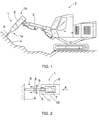
- a breaking hammer 1 is arranged on a boom 3 in an excavator 2.
- the breaking hammer 1 may be a hydraulic, pneumatic or electric device.
- the breaking device 1 is pressed by means of the boom 3 against material 4 to be broken at the same time as compression stress pulses may be given to a tool 6 connected to the hammer with a percussion device 5 in the hammer, and the tool 6 transmits the stress pulses to the material to be broken.
- the percussion device 5 usually comprises a reciprocating percussion piston striking a percussion surface at the upper end of the tool 6.
- the percussion element may be an element other than a reciprocating percussion piston.
- the breaking hammer 1 refers to the end on the side of the tool 6, while the upper part 1b of the breaking hammer refers to the end by which the breaking hammer 1 is attachable to the boom 3 or the like.
- the breaking hammer 1 may be arranged in any movable basic machine or, for instance, on a boom attached to a fixed base, such as a rock crusher.
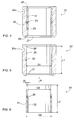
- Figure 2 shows a very simplified operating principle of a breaking device.
- a percussion element 7 of the percussion device 5 generates in the tool 6 compression stress (-), which propagates in the tool 6 as stress waves.
- - compression stress
- part of it may move on to the material 4 to be broken, and part may return as a reflected wave back towards the percussion device 5.
- Travelling in the tool 6, the stress wave 6 generates a sudden small bulge 8 in the tool 6, in other words there is a sharp hammering movement 9 in the direction of the perpendicular of the tool surface in the tool 6.
- the tool 6 is bearing-mounted on a frame 10 in the breaking device 1 by means of one or more bearings 11.
- the bearing 11 is a slide bearing that is in contact with the tool 6.
- the radial hammering movement in the tool 6 is transmitted from the surface of the tool 6 also to the bearing 11, this feature being utilized in the actual attaching process of the bearing 11 in the invention.
- Figures 3 to 10 and the related description present embodiments and details of the bearing in greater detail.
- Figure 3 shows a part of the lower part 1 a of the breaking hammer.
- the percussion element 7 may be a movable percussion piston that strikes a percussion surface 12 at the upper end of the tool 6.
- the tool 6 is arranged in the axial direction in the percussion element 7 and may be supported against the frame 10 by means of an upper bearing bushing 13 and a lower bearing bushing 14.
- the breaking hammer 1 may comprise retainer means allowing a predetermined axial movement for the tool 6 but preventing the tool 6 from getting completely out of the breaking device 1.
- Such retainer means may comprise one or more cross-direction retainer pins 15, for which a cross-direction opening is formed in the frame 10.
- a thinned portion 16 may be formed in it at the point of the retainer pin 15.
- the upper bearing bushing 13 may be arranged in the upper bearing space 17 from the direction of the percussion element 7 when the frame of the breaking device has been disassembled.
- the upper bearing bushing 13 may be supported in the axial direction with a shoulder 18 and a counter-ring 19 or the like.
- the upper bearing bushing 13 may be manufactured of slide bearing metal, and it may contain lubricant channels along which lubricant may be conveyed to its slide surfaces.
- the lower part of the frame 10 is provided with a space 20 open towards the outer surface of the frame 10, in which space 20 a tool bushing 21 is arranged from below, in the mounting direction A, the tool bushing 21 comprising a bushing frame 22 and a lower bearing bushing 14 arranged inside it.
- the tool bushing 21 is supported by its upper end against a shoulder 23 in the frame 10 and locked with one or more locking means, such as a cross-direction locking pin 24a and locking grooves 24b and 24c in such a way that it cannot get out of the space 20.
- the inner periphery of the bushing frame 22 forms a bearing space 25, into which the bearing bushing 14 is inserted.
- the end of the bushing frame 22 on the side of the percussion element may comprise a shoulder 26, against which the bearing bushing 14 may be inserted.
- the movement of the bearing bushing 14 in the axial direction may be prevented in such a way that the shoulder 23 in the frame 10 extends to the portion of the bearing bushing 14 as well.
- the purpose of the prelocking member 28 is to prevent the bearing bushing 14 from getting out of the bearing space 25 after the mounting and before the bearing bushing 14 has been attached to the bearing space 25 as a result of the deformation.
- the prelocking member 28 may be a cross-direction pin or another member suitable for the purpose.
- the lower bearing bushing 14 When the lower bearing bushing 14 has worn out, it may be replaced through the lower part of the breaking hammer without having to disassemble the lower part of the frame 10, or without even having to detach the tool bushing 21.
- the bearing bushing 14 may be provided with one or more lubricant channels 29, along which lubricant may be conveyed to its slide surfaces.
- the bushing frame 22 may comprise channels 30, as may the frame 10, for conveying lubricant to the bearing bushing 14.
- Figure 4 shows the assembled tool bushing 21.
- Figure 5 shows the bushing frame 22 and the diameter D1 of the bearing space 25.
- Figure 6 shows the bearing bushing 14 and its outer diameter D2.
- the diameter D1 has been dimensioned greater than the diameter D2, in other words there is a small clearance between the bearing bushing 14 and the bearing space 25.
- the components arranged within each other have thus a clearance fit.
- the distance between the shoulder 26 and the groove 27 in the bushing frame 22, i.e. the length L1 of the bearing space 25 is greater than or equal to the length L2 of the bearing bushing 14 in order for the bearing bushing 14 to be arrangeable inside the bushing frame 22.
- Figure 6 further shows the outer periphery 31 of the bearing bushing 14, serving as the attachment surface against the bearing space 25, and the inner periphery 32 of the bearing bushing 14, serving as the slide surface against the tool 6.
- Figure 6 indicates the wall thickness W of the bearing bushing 14, which may be between 8 to 12 mm.
- the bearing bushing 14 is sufficiently firm so that required compression stress can be generated in it as a result of radial deformation. If the bearing bushing 14 is not sufficiently firm, it does not stay properly in place in the bearing space 25. On the other hand, the wall thickness W of the bearing bushing 14 may not be so great that the stress waves 9 are not capable to generate radial deformation in the bearing bushing.
- Figure 6 indicates the inner diameter D3 of the bearing bushing 14, dimensioned greater than the outer diameter of the tool 6 in order for the slide bearing to function in general.
- Figure 7 shows an alternative structure of the lower part 1 a of the breaking hammer, in which, deviating from Figure 3 , there is no bushing frame 22 but the lower bearing bushing 14 is arranged in the bearing space 25 formed in the lower part of the frame 10.
- the lower part of the bearing space 25 may extend as far as to the outer surface of the lower part of the frame 10, whereby the bearing bushing 14 may be pushed in the mounting direction A from below to its place in the bearing space 25 without having to disassemble the frame 10.
- the bearing bushing 14 may be supported by its upper end against the shoulder 23 formed in the frame 10. By its lower end, the bearing bushing 14 may be supported with a suitable prelocking member 28 at least until it has been deformed in the radial direction against the bearing space 25 and locked in place.
- Figures 8 and 9 illustrate how the bearing bushing 14 is attached to the bearing space 25.
- the stress waves 9 travelling in the tool 6 generate on the tool surface a movement in the direction of its perpendicular, the movement being transmitted to the bearing bushing 14. This small hammering movement is illustrated with arrows in Figure 8 .
- After the mounting there is a small clearance 33 between the bearing bushing 14 and the bearing space 25.
- the hammering movement due to the stress waves shapes the bearing bushing 14 and causes the bearing bushing 14 to expand, whereby its outer periphery is pressed against the bearing space 25, and the clearance 33 disappears.
- the bearing space 25 may be of steel or corresponding material that is stronger than the bearing material and is capable of receiving the compression stress caused by the expansion of the bearing bushing 14 without the bearing space 25 being essentially deformed.
- the bearing bushing 14 may be manufactured of suitable bearing metal, such as bearing bronze. Alternatively, the bearing bushing 14 may be manufactured of any deformable slide bearing material, even plastic material or the like.
- Figure 10 illustrates two alternative ways to remove the bearing bushing 14 deformed by the stress waves 9 from the bearing space 25.
- the tool 6 is detached, and the prelocking member 28 is removed if it is still there after the use.
- one or more longitudinal welding beads 34 may be welded on the inner periphery of the bearing bushing 14, which causes the bearing bushing 14 to contract in such a way that it can be drawn out of the bearing space 25.
- One possibility is to cut in the bearing bushing 14 a longitudinal through-groove 35, in which case the bearing bushing 14 may be pressed into a smaller diameter and subsequently drawn out of the bearing space 25.
- the bearing bushing 14 can be removed with conventional tools in working site conditions.
- the upper bearing bushing 13 is attached to its place in the upper bearing space 17 by using stress waves 9 travelling in the tool 6, which stress waves deform the bearing bushing 13 in the radial direction and cause it to be pressed firmly against the bearing space 17.
- the upper bearing bushing 13 may be supported against the bearing space 17 with one or more prelocking members 28, due to which it is not necessary to support it in the way shown in Figure 3 by means of a shoulder 18 and a counter-ring 19.
- FIG 11 shows a rock drilling machine 40, which may be arranged on a feed beam 41 on the boom 3 of the rock drilling rig.
- the rock drilling machine 40 is also some kind of a breaking device comprising a percussion device 5.
- a compression stress pulse may be generated in the tool 6 on an extension of the percussion device 5.
- the tool 6 may comprise a drill shank 6a and one or more extension rods 6b and 6c, and further, there may be a drill bit 6d at the outermost end of the tool.
- the rock drilling machine 40 may further comprise a rotating device 42, with which the tool 6 can be rotated around its longitudinal axis.
- the rock drilling machine 40 may be moved by means of a feed device 43, supported by the feed beam 41.
- the end of the rock drilling machine 40 on the side of the drill shank 6a may be called the lower part or the lower end.
- Figure 12 shows the structure of the rock drilling machine 40.
- the drill shank 6a may be supported against the frame 10 with one or more bearing bushings 14 manufactured of slide bearing material.
- the bearing bushing 14 is arranged in the bearing space 25 that may be formed directly in the frame 10 of the rock drilling machine or in a separate piece attachable to and detachable from a space formed in the frame for this purpose.
- the bearing space 25 may be arranged at the lower end of the rock drilling machine 40, i.e. at the end on the side of the drill bit 6a, in such a way that the bearing bushing 14 may be inserted to its place without disassembling the frame 10.
- the preattachment of the bearing bushing 14 and the actual locking in place in the bearing space 25 may take place in the ways described earlier in this application.
- the rotation is switched off until the impact pulses given with the percussion device have caused the bearing bushing 14 to be deformed and pressed into the bearing space 25. After this, the rotation may be switched on, and the normal drilling may be started.
Landscapes
- Engineering & Computer Science (AREA)
- Mechanical Engineering (AREA)
- Mining & Mineral Resources (AREA)
- Civil Engineering (AREA)
- General Engineering & Computer Science (AREA)
- Structural Engineering (AREA)
- Percussive Tools And Related Accessories (AREA)
Abstract
Description
- The invention relates to a method for fitting a breaking device tool with a bearing, a breaking device and a tool bushing used for a bearing. The breaking device comprises at least a frame, a tool and a percussion device. By means of a percussion element in the percussion device, compression stress pulses are generated in the tool, which transmits them further to material to be broken. In a bearing space around the tool a bearing bushing is arranged, a sliding surface on the inner periphery of the bearing bushing fitting the tool with a bearing to be movable in the axial direction of the tool. The object of the invention is described in more detail in the preambles of the independent claims.
- A breaking hammer is a breaking device used as a supplementary device of an excavator or another basic machine when the intention is to break for instance rock, concrete or other relatively hard material. The percussion device of the breaking hammer is used to give compression stress pulses to a tool attached to the breaking hammer, the tool transmitting the stress pulses to the material to be broken. At the same time, the tool is pressed against the material to be broken, whereby the effect of the stress waves and pressing causes the tool to penetrate into the material to be broken, which results in breaking of the material. The tool of the breaking device is mounted on a bearing in the frame of the breaking device in such a way that it can move in the axial direction during the breaking. The tool is usually mounted on a slide bearing by means of one or more bearing bushings. In known solutions, the bearing bushing is attached to a tool bushing that is, in turn, attached to the frame of the breaking device. The bearing bushing is a slide bearing that wears in use, due to which it has to be changed from time to time. A problem with known solutions is that it is difficult and slow to change a worn bearing bushing in working site conditions.
- An object of this invention is to provide a novel and an improved method for fitting a breaking device tool with a bearing, a breaking device and a tool bushing.
- The method according to the invention is characterized by arranging a clearance fit between the outer diameter of the bearing bushing and the diameter of the bearing space; inserting the bearing bushing in the axial direction to its place in the bearing space without a force effect resulting from the reciprocal dimensioning of the diameters of the bearing bushing and the bearing space; and locking the bearing bushing during the use of the breaking device in the axial direction to be substantially immovable in such a way that the tool is subjected to compression stress pulses, whereby the stress waves in the tool generate a movement perpendicular to the surface of the tool, which movement is transmitted to the bearing bushing, causing plastic deformation to the bearing bushing, and the bearing bushing to be locked in place in the bearing space.
- The breaking device according to the invention is characterized in that a clearance fit is arranged between the outer diameter of the bearing bushing and the diameter of the bearing space; that the bearing bushing is of deformable bearing material; that the bearing bushing is prevented in the axial direction from getting out of the bearing space after the mounting; and that the bearing bushing is locked in place in the bearing space during the use of the breaking device when the stress waves in the tool and the movement in the direction of the perpendicular of the tool surface due to the waves have caused the bearing bushing to be deformed against the bearing space.
- The tool bushing according to the invention is characterized in that there is a clearance between the outer diameter of the bearing bushing and the bearing space, whereby the bearing bushing is movable in the axial direction against the shoulder and away from it without the bushing frame preventing it; that the tool bushing comprises at least one locking means with which the bearing bushing is prevented in the axial direction from getting out of the bushing frame; and that the bearing bushing is of deformable material, whereby it is arranged, during the use of the breaking device, to be deformed and to lock immovably in the bearing space.
- An idea of the invention is that the breaking device tool is arranged through at least one bearing bushing, which fits the tool with a bearing in such a way that the tool can move in the axial direction relative to the frame of the breaking device. The bearing bushing is an elongated piece made of slide bearing material and arranged in the bearing space. A clearance fit is arranged between the outer diameter of the bearing bushing and the bearing space to facilitate the mounting of the bearing bushing. During the use, the bearing bushing is arranged to be subjected to stress waves of the compression stress pulses travelling in the tool, whereby the bearing bushing is arranged to be deformed by the effect of the stress waves. The periphery of the bearing bushing is enlarged in the direction of the periphery and deformed. The enlargement of the bearing bushing periphery results in compression stress between the bearing bushing and the bearing space, which locks the bushing to be immovable. Thus, in the solution according to the invention, the stress waves generated by a percussion device have two tasks: primarily they contribute to the breaking of the material to be treated, but they also cause the bearing bushing of the tool to be actually attached to its place in the bearing space.
- An advantage of the invention is that the bearing bushing can be easily inserted in the axial direction to its place in the bearing space, since there is a clearance fit between the bearing space and the bearing bushing. No special pressing tools or the like are required for the mounting, but the bearing bushing can be inserted into the bearing space with manual force. Further, the bearing bushing is a simple utility item the manufacturing costs of which are small.
- The idea of an embodiment of the invention is that the bearing bushing is prevented in the axial direction from getting out of the bearing space by means of one or more prelocking members. The prelocking member keeps the bearing bushing temporarily in place until the bearing bushing is deformed and actually attached to the bearing space.
- The idea of an embodiment of the invention is that at least one bearing space is positioned at the lower end of the breaking device on the side of the tool in such a way that the bearing space is open downwards in the axial direction. Thus, the bearing bushing is insertable in the axial direction from below to its place in the bearing space without having to disassemble the lower frame of the breaking device. For changing, only the tool needs to be detached. An advantage of this embodiment is that it is quick and simple to change the bearing bushing. Further, since there is no need to disassemble structures of the breaking device, the changing may also take place in dirty working site conditions. As it is possible to change the bearing bushing in the working site, the interruption in the use of the breaking device can be as short as possible.
- The idea of an embodiment of the invention is that the breaking device comprises a tool bushing comprising a bushing frame the inner circle of which forms a bearing space for the bearing bushing. The bushing frame may be immovably attached to the frame of the breaking device by means of one or more locking means. The bearing bushing is arranged to be deformed during the operation of the breaking device in such a way that it is pressed against the inner periphery of the bushing frame in the radial direction. The strength of the bushing frame is dimensioned to be greater than that of the bearing bushing so that substantially only the bearing bushing is deformed by the effect of stress waves. An advantage of this embodiment is that the bushing frame and the bearing space in it may be detached and changed, if required. Further, the tool bushings of the present breaking devices already in use may be replaced with tool bushings according to this embodiment, after which it will be easier to change the bearing bushings in the future.
- The idea of an embodiment of the invention is that the bearing space is formed directly in the frame of the breaking device. Thus, the bearing bushing is arranged to be deformed against the frame of the breaking device during the use of the device. An advantage of this embodiment is that the breaking device does not need a separate bushing frame to form a bearing space. Thus, the diameter of the hole to be made around the tool in the breaking device frame may be smaller than when a separate detachable bushing frame is used, which reduces the manufacturing costs. In addition, there is no need to manufacture a bushing frame. Furthermore, the bearing space formed in the breaking device frame is particularly firm, whereby it can well receive the compression stress of the bearing bushing deformed during the use.
- The idea of an embodiment of the invention is that the bearing bushing is of bearing bronze. Bearing bronze suits well to be used as the slide bearing of a breaking device tool, because it is deformed relatively easily due to the effect of stress waves, still having sufficient yield strength so that deformation causes compression stress in it, which keeps the bearing bushing in place in the bearing space due to the friction between the bearing bushing and the bearing space. Further, an advantage of bearing bronze is that it endures also short-term dry use without getting damaged when, for some reason or other, there is no lubricant film between the bearing bushing and the tool.
- The idea of an embodiment of the invention is that the wall thickness of the bearing bushing is between 8 and 12 mm. Thus, the bearing bushing is sufficiently firm, so that sufficient compression stress is generated in it as a result of radial deformation. If the bearing bushing is not sufficiently firm, it does not stay properly in place in the bearing space. On the other hand, the wall thickness of the bearing bushing may not be so great that stress waves are not sufficient to generate deformation.
- The idea of an embodiment of the invention is that the bearing bushing is prevented, by means of one or more prelocking member of light material, from getting out of the bearing space. An advantage of a lightweight prelocking member is that it is not subjected to such great acceleration forces during the operation of the percussion device as would a piece manufactured of denser material. The density of the prelocking member may be clearly smaller than that of the frame material. The density of the prelocking member material may be below 3 000 kg/m3, whereas the density of the frame that is typically steel is about 8 0000 kg/m3. Thus, the prelocking member may be manufactured of, for example, plastic material or reinforced plastic that has been reinforced with carbon, aramid or glass fibres or the like fibres. Further, the prelocking member may be manufactured of light metal, such as aluminium alloy. Furthermore, it may be manufactured of fibre material or even rubber. A prelocking member manufactured of light material does not, due to vibration, deform the locking surface made for it, such as a locking groove, locking opening or the like, because the acceleration forces directed at the prelocking member are relatively small. On the other hand, a prelocking member manufactured of less dense material is usually softer than a locking surface manufactured of denser material. A prelocking member manufactured of less dense material than the locking surface may wear during the use due to vibration, but this has no significance because the purpose of the prelocking member is to keep the bearing bushing in the bearing space only until some stress compression pulses have been given to the tool by the percussion device and until the stress waves in the tool have deformed the bearing bushing in such a way that it is firmly pressed into the bearing space.
- The idea of an embodiment of the invention is that the prelocking member is a ring manufactured of plastic material, arranged in a groove on the periphery of the bearing space. It is simple and quick to arrange such a locking ring in place. Further, it is easy to manufacture inexpensive high-quality locking members of plastic material.
- Some embodiments of the invention will be described in more detail in the attached drawings, in which
-
Figure 1 shows schematically a side view of a breaking hammer arranged in the boom of an excavator; -
Figure 2 shows schematically generation of a compression stress pulse in a tool that transmits the generated stress waves to the material to be broken; -
Figure 3 shows schematically a cut-open part of the lower part of a breaking device; -
Figure 4 shows schematically a side view of a cut-open tool bushing; -
Figure 5 shows schematically a side view of the cut-open bushing frame of the tool bushing according toFigure 4 ; -
Figure 6 shows schematically a side view of the cut-open bearing bushing of the tool bushing according toFigure 4 ; -
Figure 7 shows schematically an open-cut part of the lower part of another breaking hammer; -
Figure 8 shows schematically a cross-section of the bearing of a tool according to the invention, seen from the longitudinal direction of the tool, before the bearing bushing has been deformed; -
Figure 9 shows schematically a cross-section of the bearing of a tool according to the invention, seen from the longitudinal direction of the tool, after the bearing bushing has been deformed by the effect of stress waves; -
Figure 10 shows schematically a cross-section indicating alternative ways to remove the bearing bushing deformed into the bearing housing; -
Figure 11 shows schematically a side view of a rock drilling machine; and -
Figure 12 shows schematically an open-cut structure of a rock drilling machine. - For the sake of clarity, embodiments of the invention are shown simplified in the figures. Similar parts are indicated with the same reference numerals.
- In
Figure 1 , a breaking hammer 1 is arranged on aboom 3 in anexcavator 2. The breaking hammer 1 may be a hydraulic, pneumatic or electric device. The breaking device 1 is pressed by means of theboom 3 againstmaterial 4 to be broken at the same time as compression stress pulses may be given to atool 6 connected to the hammer with apercussion device 5 in the hammer, and thetool 6 transmits the stress pulses to the material to be broken. Thepercussion device 5 usually comprises a reciprocating percussion piston striking a percussion surface at the upper end of thetool 6. In some cases, the percussion element may be an element other than a reciprocating percussion piston. Further, there may be a protective casing around the breaking hammer 1, protecting it against damages and impurities. - It can be noted that in this application the
lower part 1 a of the breaking hammer refers to the end on the side of thetool 6, while theupper part 1b of the breaking hammer refers to the end by which the breaking hammer 1 is attachable to theboom 3 or the like. Further, the breaking hammer 1 may be arranged in any movable basic machine or, for instance, on a boom attached to a fixed base, such as a rock crusher. -
Figure 2 shows a very simplified operating principle of a breaking device. Apercussion element 7 of thepercussion device 5 generates in thetool 6 compression stress (-), which propagates in thetool 6 as stress waves. When a stress wave has reached the outermost end of thetool 6, part of it may move on to thematerial 4 to be broken, and part may return as a reflected wave back towards thepercussion device 5. Travelling in thetool 6, thestress wave 6 generates a suddensmall bulge 8 in thetool 6, in other words there is asharp hammering movement 9 in the direction of the perpendicular of the tool surface in thetool 6. - Further, it can be seen from
Figure 2 that thetool 6 is bearing-mounted on aframe 10 in the breaking device 1 by means of one ormore bearings 11. Thebearing 11 is a slide bearing that is in contact with thetool 6. Thus, the radial hammering movement in thetool 6 is transmitted from the surface of thetool 6 also to thebearing 11, this feature being utilized in the actual attaching process of the bearing 11 in the invention.Figures 3 to 10 and the related description present embodiments and details of the bearing in greater detail. -
Figure 3 shows a part of thelower part 1 a of the breaking hammer. Thepercussion element 7 may be a movable percussion piston that strikes apercussion surface 12 at the upper end of thetool 6. Thetool 6 is arranged in the axial direction in thepercussion element 7 and may be supported against theframe 10 by means of anupper bearing bushing 13 and alower bearing bushing 14. The breaking hammer 1 may comprise retainer means allowing a predetermined axial movement for thetool 6 but preventing thetool 6 from getting completely out of the breaking device 1. Such retainer means may comprise one or more cross-direction retainer pins 15, for which a cross-direction opening is formed in theframe 10. Further, in order for thetool 6 to be able to move relative to theretainer pin 15, a thinnedportion 16 may be formed in it at the point of theretainer pin 15. Theupper bearing bushing 13 may be arranged in theupper bearing space 17 from the direction of thepercussion element 7 when the frame of the breaking device has been disassembled. Theupper bearing bushing 13 may be supported in the axial direction with ashoulder 18 and a counter-ring 19 or the like. Theupper bearing bushing 13 may be manufactured of slide bearing metal, and it may contain lubricant channels along which lubricant may be conveyed to its slide surfaces. - The lower part of the
frame 10 is provided with aspace 20 open towards the outer surface of theframe 10, in which space 20 atool bushing 21 is arranged from below, in the mounting direction A, thetool bushing 21 comprising abushing frame 22 and alower bearing bushing 14 arranged inside it. Thetool bushing 21 is supported by its upper end against ashoulder 23 in theframe 10 and locked with one or more locking means, such as across-direction locking pin 24a and lockinggrooves space 20. The inner periphery of thebushing frame 22 forms a bearingspace 25, into which the bearingbushing 14 is inserted. The end of thebushing frame 22 on the side of the percussion element may comprise ashoulder 26, against which the bearingbushing 14 may be inserted. Alternatively, the movement of the bearingbushing 14 in the axial direction may be prevented in such a way that theshoulder 23 in theframe 10 extends to the portion of the bearingbushing 14 as well. In the portion of the opposite end of thebushing frame 22, there may be agroove 27, which may be provided with aprelocking member 28, such as a ring made of plastic material. The purpose of the prelockingmember 28 is to prevent the bearingbushing 14 from getting out of the bearingspace 25 after the mounting and before the bearingbushing 14 has been attached to the bearingspace 25 as a result of the deformation. Alternatively, the prelockingmember 28 may be a cross-direction pin or another member suitable for the purpose. When thelower bearing bushing 14 has worn out, it may be replaced through the lower part of the breaking hammer without having to disassemble the lower part of theframe 10, or without even having to detach thetool bushing 21. - It can be seen from
Figure 3 that the bearingbushing 14 may be provided with one ormore lubricant channels 29, along which lubricant may be conveyed to its slide surfaces. Correspondingly, thebushing frame 22 may comprisechannels 30, as may theframe 10, for conveying lubricant to the bearingbushing 14. -
Figure 4 shows the assembledtool bushing 21.Figure 5 shows thebushing frame 22 and the diameter D1 of the bearingspace 25.Figure 6 , in turn, shows the bearingbushing 14 and its outer diameter D2. In order to insert the bearingbushing 14 into the bearingspace 25 without difficulty in the mounting direction A, the diameter D1 has been dimensioned greater than the diameter D2, in other words there is a small clearance between the bearingbushing 14 and the bearingspace 25. The components arranged within each other have thus a clearance fit. Further, the distance between theshoulder 26 and thegroove 27 in thebushing frame 22, i.e. the length L1 of the bearingspace 25, is greater than or equal to the length L2 of the bearingbushing 14 in order for the bearingbushing 14 to be arrangeable inside thebushing frame 22.Figure 6 further shows theouter periphery 31 of the bearingbushing 14, serving as the attachment surface against the bearingspace 25, and theinner periphery 32 of the bearingbushing 14, serving as the slide surface against thetool 6. Further,Figure 6 indicates the wall thickness W of the bearingbushing 14, which may be between 8 to 12 mm. Thus, the bearingbushing 14 is sufficiently firm so that required compression stress can be generated in it as a result of radial deformation. If the bearingbushing 14 is not sufficiently firm, it does not stay properly in place in the bearingspace 25. On the other hand, the wall thickness W of the bearingbushing 14 may not be so great that the stress waves 9 are not capable to generate radial deformation in the bearing bushing. Furthermore,Figure 6 indicates the inner diameter D3 of the bearingbushing 14, dimensioned greater than the outer diameter of thetool 6 in order for the slide bearing to function in general. -
Figure 7 shows an alternative structure of thelower part 1 a of the breaking hammer, in which, deviating fromFigure 3 , there is nobushing frame 22 but thelower bearing bushing 14 is arranged in the bearingspace 25 formed in the lower part of theframe 10. The lower part of the bearingspace 25 may extend as far as to the outer surface of the lower part of theframe 10, whereby the bearingbushing 14 may be pushed in the mounting direction A from below to its place in the bearingspace 25 without having to disassemble theframe 10. The bearingbushing 14 may be supported by its upper end against theshoulder 23 formed in theframe 10. By its lower end, the bearingbushing 14 may be supported with asuitable prelocking member 28 at least until it has been deformed in the radial direction against the bearingspace 25 and locked in place. -
Figures 8 and 9 illustrate how the bearingbushing 14 is attached to the bearingspace 25. The stress waves 9 travelling in thetool 6 generate on the tool surface a movement in the direction of its perpendicular, the movement being transmitted to the bearingbushing 14. This small hammering movement is illustrated with arrows inFigure 8 . After the mounting, there is asmall clearance 33 between the bearingbushing 14 and the bearingspace 25. The hammering movement due to the stress waves shapes the bearingbushing 14 and causes the bearingbushing 14 to expand, whereby its outer periphery is pressed against the bearingspace 25, and theclearance 33 disappears. - It is seen from
Figure 9 that during the use thetool 6 is supported, due toclearances 39 between thetool 6 and the bearingbushing 14, against onesupport point 36 of the side of the bearingbushing 14. In practice, thetool 6 becomes thus positioned eccentrically inside the bearingbushing 14. Due to this, during one stress wave, hammering movement is transmitted to the bearingbushing 14 essentially only at thesupport point 36. As seen fromFigure 9 , for example the opposite side of thesupport point 36 has amaximum clearance 39a, and the small bulge on the surface of thetool 6 is not capable of affecting the bearingbushing 14. However, the position of thetool 6 inside the bearingbushing 14 changes continuously during the use of the breaking hammer, so that forces which deform are directed at different points on the periphery of the bearingbushing 14. When thesupport point 36 is subjected to aradial force 37 caused by a stress wave and shown inFigure 9 , the bearingbushing 14 is pressed between thetool 6 and the bearinghousing 25, due to which the periphery of the bearingbushing 14 tends to stretch in the way indicated witharrows 38. When the periphery of the bearingbushing 14 stretches, it expands and causes radial deformation of the whole bushing. The diameter of the bearingbushing 14 enlarges permanently, and the bushing is firmly pressed against the bearinghousing 25. - The bearing
space 25 may be of steel or corresponding material that is stronger than the bearing material and is capable of receiving the compression stress caused by the expansion of the bearingbushing 14 without the bearingspace 25 being essentially deformed. The bearingbushing 14 may be manufactured of suitable bearing metal, such as bearing bronze. Alternatively, the bearingbushing 14 may be manufactured of any deformable slide bearing material, even plastic material or the like. -
Figure 10 illustrates two alternative ways to remove the bearingbushing 14 deformed by the stress waves 9 from the bearingspace 25. Before removing the bearingbushing 14, thetool 6 is detached, and theprelocking member 28 is removed if it is still there after the use. Subsequently, one or morelongitudinal welding beads 34 may be welded on the inner periphery of the bearingbushing 14, which causes the bearingbushing 14 to contract in such a way that it can be drawn out of the bearingspace 25. One possibility is to cut in the bearing bushing 14 a longitudinal through-groove 35, in which case the bearingbushing 14 may be pressed into a smaller diameter and subsequently drawn out of the bearingspace 25. The bearingbushing 14 can be removed with conventional tools in working site conditions. - It is also feasible to apply the solution according to the invention in connection with the upper bearing bushing 13 of the breaking
hammer tool 6. In such a case, also theupper bearing bushing 13 is attached to its place in theupper bearing space 17 by usingstress waves 9 travelling in thetool 6, which stress waves deform the bearingbushing 13 in the radial direction and cause it to be pressed firmly against the bearingspace 17. Theupper bearing bushing 13 may be supported against the bearingspace 17 with one ormore prelocking members 28, due to which it is not necessary to support it in the way shown inFigure 3 by means of ashoulder 18 and a counter-ring 19. -
Figure 11 shows arock drilling machine 40, which may be arranged on afeed beam 41 on theboom 3 of the rock drilling rig. Therock drilling machine 40 is also some kind of a breaking device comprising apercussion device 5. By means of thepercussion element 7 in thepercussion device 5, a compression stress pulse may be generated in thetool 6 on an extension of thepercussion device 5. Thetool 6 may comprise adrill shank 6a and one ormore extension rods drill bit 6d at the outermost end of the tool. Therock drilling machine 40 may further comprise arotating device 42, with which thetool 6 can be rotated around its longitudinal axis. Furthermore, therock drilling machine 40 may be moved by means of afeed device 43, supported by thefeed beam 41. In this application, the end of therock drilling machine 40 on the side of thedrill shank 6a may be called the lower part or the lower end. -
Figure 12 shows the structure of therock drilling machine 40. Thedrill shank 6a may be supported against theframe 10 with one ormore bearing bushings 14 manufactured of slide bearing material. The bearingbushing 14 is arranged in the bearingspace 25 that may be formed directly in theframe 10 of the rock drilling machine or in a separate piece attachable to and detachable from a space formed in the frame for this purpose. The bearingspace 25 may be arranged at the lower end of therock drilling machine 40, i.e. at the end on the side of thedrill bit 6a, in such a way that the bearingbushing 14 may be inserted to its place without disassembling theframe 10. The preattachment of the bearingbushing 14 and the actual locking in place in the bearingspace 25 may take place in the ways described earlier in this application. After the bearingbushing 14 has been mounted, the rotation is switched off until the impact pulses given with the percussion device have caused the bearingbushing 14 to be deformed and pressed into the bearingspace 25. After this, the rotation may be switched on, and the normal drilling may be started. - In some cases, the features presented in this application may be used as such, irrespective of the other features. On the other hand, features described in this application may, if required, be combined to form different combinations.
- The drawings and the related description are only intended to illustrate the idea of the invention. Details of the invention may vary within the scope of the claims.
Claims (15)
- A method for fitting a breaking device tool with a bearing,
the breaking device (1, 40) comprising: a frame (10); a tool (6); and a percussion device (5), which has a percussion element (7) with which compression stress pulses may be generated in the tool (6), which transmits them further to material (4) to be broken;
and the method comprising:arranging around the tool (6) at least one bearing bushing (14) having an outer periphery (31) and inner periphery (32);attaching the bearing bushing (14) immovably in an annular bearing space (25) around the tool (6); andfitting the tool (6) with a bearing by means of a slide surface on the inner periphery (32) of the bearing bushing (14) to be movable in the axial direction,characterized by
arranging a clearance fit between the outer diameter (D2) of the bearing bushing (14) and the diameter (D1) of the bearing space (25);
inserting the bearing bushing (14) in the axial direction to its place in the bearing space (25) without a force effect resulting from the reciprocal dimensioning of the diameters (D1, D2) of the bearing bushing (14) and the bearing space (25); and
locking the bearing bushing (14) during the use of the breaking device (1) in the axial direction to be substantially immovable in such a way that the tool (6) is subjected to compression stress pulses, whereby the stress waves in the tool generate a movement perpendicular to the surface of the tool (6), which movement is transmitted to the bearing bushing (14), causing plastic deformation to the bearing bushing, and the bearing bushing to be locked in place in the bearing space (25). - A method according to claim 1, characterized by
arranging at the lower end of the frame (10) on the side of the tool a bearing space (25) connected to the outer surface of the lower part of the frame; and
arranging the lowest bearing bushing (14) in place in the bearing space (25) by pushing from below, without disassembling the frame. - A method according to claim 1 or 2, characterized by
arranging at the lower end of the frame (10) on the side of the tool a space (20) connected to the outer surface of the frame; and
arranging in said space (20) a tool bushing that comprises an elongated bushing frame (22), and locking the tool immovably by means of at least one locking member (24a); and
arranging a bearing bushing (14) in the bearing space (25) in the bushing frame (22). - A method according to any one of the preceding claims,
characterized by
preventing the bearing bushing (14) from getting out of the bearing space (25) in the axial direction by means of at least one prelocking member (28). - A method according to claim 4, characterized by
prelocking the bearing bushing (14) in place in the axial direction by means of a prelocking member (28) manufactured of plastic material. - A breaking device comprising:a frame (10);a percussion device (5) having a percussion element (7) for generating compression stress pulses;a tool (6) arranged on the extension of the percussion element (7) and arranged to transmit the compression stress pulses to material (4) to be broken as stress waves (9); andat least one bearing bushing (14) arranged in a bearing space (25) around the tool (6), which bearing bushing (14) is of bearing material, whereby it is arranged to form a slide bearing for the tool (6) moved in the axial direction,characterized in
that a clearance fit is arranged between the outer diameter (D2) of the bearing bushing (14) and the diameter (D1) of the bearing space (25);
that the bearing bushing (14) is of deformable bearing material;
that the bearing bushing (14) is prevented in the axial direction from getting out of the bearing space (25) after the mounting; and
that the bearing bushing (14) is locked in place in the bearing space (25) during the use of the breaking device (1) when the stress waves in the tool (6) and the movement in the direction of the perpendicular of the tool (6) surface due to the waves have caused the bearing bushing (14) to be deformed against the bearing space (25). - A breaking device according to claim 6, characterized in
that the bearing bushing (14) is prevented in the axial direction from getting out of the bearing space (25) after the mounting by means of at least one prelocking member (28). - A breaking device according to claim 7, characterized in
that the prelocking member (28) is manufactured of light material, the density of which is below 3 000 kg/m3. - A breaking device according to any one of the preceding claims 6 to 8, characterized in
that the breaking device (1) comprises a tool bushing (21) that is a separate piece attachable to the frame (10) of the breaking device;
that the tool bushing (21) comprises an elongated bushing frame (22) having an outer periphery and an inner periphery; and
that the inner periphery of the bushing frame (22) serves as the bearing space (25), in which the bearing bushing (14) is arranged. - A breaking device according to any one of the preceding claims 6 to 8, characterized in
that the bearing space (25) is formed directly in the frame (10) of the breaking device. - A breaking device according to any one of the preceding claims 6 to 10, characterized in
that the bearing bushing (14) is manufactured of bearing bronze. - A breaking device according to any one of the preceding claims 6 to 11, characterized in
that the breaking device is a breaking hammer. - A breaking device according to any one of the preceding claims 6 to 11, characterized in
that the breaking device is a rock drilling machine. - A tool bushing of a breaking device, which comprises:a bushing frame (22) that is an elongated piece having an inner periphery and an outer periphery as well as a first end and a second end;a shoulder (26) arranged on the inner periphery of the bushing frame (22), in its first end portion;at least one cross-direction locking groove (24c) on the outer periphery of the bushing frame (22) to lock a tool bushing (21) in the frame (10) of the breaking hammer by means of a retainer pin (15);at least one bearing bushing (14) that is an elongated piece manufactured of slide bearing material and that comprises an inner periphery (32) and outer periphery (31);and in which the inner periphery of the bushing frame (22) forms a bearing space (25), in which the bearing bushing (14) is arranged;characterized in
that there is a clearance (33) between the outer diameter (31) of the bearing bushing (14) and the bearing space (25), whereby the bearing bushing (14) is movable in the axial direction against the shoulder (26) and away from it without the bushing frame (22) preventing it;
that the tool bushing (21) comprises at least one locking means (27, 28) with which the bearing bushing (14) is prevented in the axial direction from getting out of the bushing frame (22); and
that the bearing bushing (14) is of deformable material, whereby it is arranged, during the use of the breaking device, to be deformed and locked immovably in the bearing space (25). - A tool bushing according to claim 14, characterized in
that the locking means comprise at least one prelocking member (28) manufactured of plastic material.
Applications Claiming Priority (1)
| Application Number | Priority Date | Filing Date | Title |
|---|---|---|---|
| FI20065775A FI119228B (en) | 2006-12-05 | 2006-12-05 | Storage of tools in crusher |
Publications (2)
| Publication Number | Publication Date |
|---|---|
| EP1930127A1 true EP1930127A1 (en) | 2008-06-11 |
| EP1930127B1 EP1930127B1 (en) | 2012-01-04 |
Family
ID=37623791
Family Applications (1)
| Application Number | Title | Priority Date | Filing Date |
|---|---|---|---|
| EP07121945A Revoked EP1930127B1 (en) | 2006-12-05 | 2007-11-30 | Method for fitting a beaking device tool with a bearing, breaking device and bearing of a breaking device |
Country Status (7)
| Country | Link |
|---|---|
| US (1) | US8550180B2 (en) |
| EP (1) | EP1930127B1 (en) |
| JP (1) | JP5351413B2 (en) |
| KR (1) | KR101379573B1 (en) |
| CN (1) | CN101195215B (en) |
| ES (1) | ES2377351T3 (en) |
| FI (1) | FI119228B (en) |
Cited By (3)
| Publication number | Priority date | Publication date | Assignee | Title |
|---|---|---|---|---|
| CN102371573A (en) * | 2010-08-10 | 2012-03-14 | 南京德朔实业有限公司 | Electric tool |
| EP2288779A4 (en) * | 2008-06-25 | 2016-03-16 | Jae-Mog Kim | Hydraulic breaker assembly |
| EP3670758A1 (en) * | 2018-12-21 | 2020-06-24 | Sandvik Mining and Construction Oy | Insert bushing arrangement, breaking hammer and related method |
Families Citing this family (15)
| Publication number | Priority date | Publication date | Assignee | Title |
|---|---|---|---|---|
| US8672052B2 (en) * | 2010-12-14 | 2014-03-18 | Caterpillar Inc. | Demolition hammer with reversible housing and interchangeable wear plate arrangement |
| FI123475B (en) * | 2011-09-15 | 2013-05-31 | Sandvik Mining & Constr Oy | Impact hammer tools, impact hammer and its use |
| GB201116287D0 (en) | 2011-09-21 | 2011-11-02 | Airbus Operations Ltd | Method and device for removing a sleeve from a bore |
| JP6211871B2 (en) * | 2013-09-26 | 2017-10-11 | 古河ロックドリル株式会社 | Front cover for hydraulic breaker and hydraulic breaker having the same |
| EP2873489B1 (en) * | 2013-11-13 | 2018-10-24 | Sandvik Mining and Construction Oy | Impact device and method of dismounting the same |
| EP2910336A1 (en) * | 2014-02-21 | 2015-08-26 | HILTI Aktiengesellschaft | Power tool |
| US20160069388A1 (en) * | 2014-09-09 | 2016-03-10 | Caterpillar Inc. | Thrust ring and method of manufacturing or refurbishing a thrust ring |
| SE540712C2 (en) | 2014-12-22 | 2018-10-16 | Husqvarna Ab | Implement coupling device and a machine provided with such adevice |
| US10730173B2 (en) | 2015-08-24 | 2020-08-04 | Stanley Black & Decker, Inc. | Hammer tacker |
| US11085254B2 (en) | 2017-12-19 | 2021-08-10 | Falcon Tools, LLC | Bit breaker technology |
| US11391101B2 (en) | 2017-12-19 | 2022-07-19 | Falcon Tools, LLC | Bit breaker technology |
| CN108915014A (en) * | 2018-05-29 | 2018-11-30 | 山东科技大学 | A kind of crawler type precipice rubble remove device |
| EP3632624A1 (en) * | 2018-10-04 | 2020-04-08 | Hilti Aktiengesellschaft | Eccentric drive for a hand-held machine tool |
| CN113738264A (en) * | 2021-10-14 | 2021-12-03 | 江苏煤炭地质机械研制中心 | Impact hammer capable of quickly replacing drill rod |
| CN115364925B (en) * | 2022-09-06 | 2023-11-10 | 中联重科股份有限公司 | Hydraulic breaking hammer assembly |
Citations (3)
| Publication number | Priority date | Publication date | Assignee | Title |
|---|---|---|---|---|
| DE29510818U1 (en) | 1995-07-04 | 1995-09-14 | Moers Baumaschinen GmbH, 58119 Hagen | Guide bush for use in a cylindrical chisel bush as part of a hydraulic hammer |
| WO2000058058A1 (en) * | 1999-03-26 | 2000-10-05 | Reginald Frederick Taylor | Hammer drill assembly |
| US6510904B1 (en) | 2000-05-26 | 2003-01-28 | Nippon Pneumatic Mfg. Co., Ltd. | Protected tool bushing for an impact hammer |
Family Cites Families (28)
| Publication number | Priority date | Publication date | Assignee | Title |
|---|---|---|---|---|
| US2512149A (en) * | 1947-02-21 | 1950-06-20 | Joy Mfg Co | Working implement retainer |
| JPS5421900B2 (en) * | 1973-02-15 | 1979-08-02 | ||
| US3917361A (en) * | 1974-01-30 | 1975-11-04 | Reed Tool Co | Friction bearing |
| DE2820128A1 (en) * | 1978-05-09 | 1979-11-22 | Bosch Gmbh Robert | CRAFT MACHINE |
| CN87204166U (en) * | 1987-04-25 | 1988-01-20 | 长沙市郊东方机电厂 | Hand hydraulic hammer |
| DE3807078A1 (en) * | 1988-03-04 | 1989-09-14 | Black & Decker Inc | DRILLING HAMMER |
| US5098837A (en) | 1988-06-07 | 1992-03-24 | Eli Lilly And Company | Macrolide biosynthetic genes for use in streptomyces and other organisms |
| JPH0632310Y2 (en) * | 1988-09-02 | 1994-08-24 | 株式会社テイサク | Attachment structure of guide bush for chisel in striking device |
| JP2769557B2 (en) | 1988-09-29 | 1998-06-25 | 中部ベアリング株式会社 | Retaining ring |
| KR920006031Y1 (en) * | 1989-08-01 | 1992-08-29 | 삼성중공업 주식회사 | Connecting device for boom in excavator |
| US5199508A (en) * | 1991-08-01 | 1993-04-06 | Kabushiki Kaisha Miyanaga | Rotary hammer drill |
| FR2692187B1 (en) * | 1992-06-16 | 1997-06-20 | Montabert Ets | DEVICE FOR HOLDING THE TOOL OF A HYDRAULIC ROCK BREAKER. |
| JP2586203Y2 (en) * | 1992-11-24 | 1998-12-02 | 古河機械金属株式会社 | Dustproof mechanism of hydraulic breaker |
| US5839517A (en) * | 1993-01-27 | 1998-11-24 | Lord Corporation | Vibration isolator for hand-held vibrating devices |
| JPH0837751A (en) | 1994-07-25 | 1996-02-06 | Sony Corp | motor |
| KR200151343Y1 (en) * | 1995-04-14 | 1999-07-15 | 최해성 | Low Noise Hydraulic Hammer |
| FI98401C (en) * | 1995-10-10 | 1997-06-10 | Tamrock Oy | A method for adjusting the drilling of a drilling machine and a rock drilling machine |
| JP3606021B2 (en) * | 1996-12-13 | 2005-01-05 | 日立工機株式会社 | Impact tool |
| US5944120A (en) * | 1997-11-10 | 1999-08-31 | Caterpillar Inc. | Hydraulic hammer assembly having low vibration characteristics |
| FI112450B (en) * | 2000-10-09 | 2003-12-15 | Sandvik Tamrock Oy | Hammer and tools |
| GB0121947D0 (en) * | 2001-09-12 | 2001-10-31 | Black & Decker Inc | Tool holder for hammer |
| US6679411B2 (en) * | 2001-12-21 | 2004-01-20 | Illinois Tool Works Inc. | Piston retention system for a fastener driving tool |
| FI121004B (en) * | 2003-01-03 | 2010-06-15 | Sandvik Mining & Constr Oy | Rock drill and axial bearing for a striking rock drill |
| JP2005155655A (en) | 2003-11-12 | 2005-06-16 | Hitachi Powdered Metals Co Ltd | Sliding bearing manufacturing method |
| FI121139B (en) * | 2004-02-02 | 2010-07-30 | Sandvik Mining & Constr Oy | Hydraulic hammer and tool sleeve |
| DE102004028371A1 (en) * | 2004-06-11 | 2005-12-29 | Hilti Ag | Beating machine tool with rinsing head |
| GB2426797B (en) * | 2005-06-01 | 2010-11-24 | Milwaukee Electric Tool Corp | Power tool |
| EP1733851B1 (en) * | 2005-06-15 | 2013-01-02 | Caterpillar Inc. | Tool Retention Apparatus and Method |
-
2006
- 2006-12-05 FI FI20065775A patent/FI119228B/en not_active IP Right Cessation
-
2007
- 2007-11-30 ES ES07121945T patent/ES2377351T3/en active Active
- 2007-11-30 EP EP07121945A patent/EP1930127B1/en not_active Revoked
- 2007-12-03 US US11/987,667 patent/US8550180B2/en not_active Expired - Fee Related
- 2007-12-05 CN CN2007101971347A patent/CN101195215B/en not_active Expired - Fee Related
- 2007-12-05 JP JP2007314835A patent/JP5351413B2/en not_active Expired - Fee Related
- 2007-12-05 KR KR1020070125787A patent/KR101379573B1/en not_active Expired - Fee Related
Patent Citations (3)
| Publication number | Priority date | Publication date | Assignee | Title |
|---|---|---|---|---|
| DE29510818U1 (en) | 1995-07-04 | 1995-09-14 | Moers Baumaschinen GmbH, 58119 Hagen | Guide bush for use in a cylindrical chisel bush as part of a hydraulic hammer |
| WO2000058058A1 (en) * | 1999-03-26 | 2000-10-05 | Reginald Frederick Taylor | Hammer drill assembly |
| US6510904B1 (en) | 2000-05-26 | 2003-01-28 | Nippon Pneumatic Mfg. Co., Ltd. | Protected tool bushing for an impact hammer |
Cited By (4)
| Publication number | Priority date | Publication date | Assignee | Title |
|---|---|---|---|---|
| EP2288779A4 (en) * | 2008-06-25 | 2016-03-16 | Jae-Mog Kim | Hydraulic breaker assembly |
| CN102371573A (en) * | 2010-08-10 | 2012-03-14 | 南京德朔实业有限公司 | Electric tool |
| EP3670758A1 (en) * | 2018-12-21 | 2020-06-24 | Sandvik Mining and Construction Oy | Insert bushing arrangement, breaking hammer and related method |
| US11338424B2 (en) | 2018-12-21 | 2022-05-24 | Sandvik Mining And Construction Oy | Insert bushing arrangement, breaking hammer and related method |
Also Published As
| Publication number | Publication date |
|---|---|
| ES2377351T3 (en) | 2012-03-26 |
| JP5351413B2 (en) | 2013-11-27 |
| US8550180B2 (en) | 2013-10-08 |
| FI20065775L (en) | 2008-06-06 |
| KR20080052456A (en) | 2008-06-11 |
| KR101379573B1 (en) | 2014-03-31 |
| CN101195215A (en) | 2008-06-11 |
| JP2008142885A (en) | 2008-06-26 |
| EP1930127B1 (en) | 2012-01-04 |
| FI119228B (en) | 2008-09-15 |
| CN101195215B (en) | 2012-01-11 |
| US20080173457A1 (en) | 2008-07-24 |
| FI20065775A0 (en) | 2006-12-05 |
Similar Documents
| Publication | Publication Date | Title |
|---|---|---|
| EP1930127B1 (en) | Method for fitting a beaking device tool with a bearing, breaking device and bearing of a breaking device | |
| RU2745395C2 (en) | Mountain machine | |
| JP5883106B2 (en) | Impact device and method for removing impact device | |
| US9095968B2 (en) | Tool for breaking hammer, breaking hammer, and use thereof | |
| FI112450B (en) | Hammer and tools | |
| KR102120971B1 (en) | Rotating type rock crushing device and the rock crushing method thereby | |
| AU2018274921A1 (en) | Mining Machine with Driven Disc Cutters | |
| RU2410519C1 (en) | Method of securing teeth in drill tool | |
| WO2008112117A1 (en) | Bit rebounding bumper for down-the-hole rock drilling hammer | |
| GB2141659A (en) | Tool retainer for a percussive tool | |
| KR102429885B1 (en) | Excavator splitting apparatus | |
| AU2020200965B2 (en) | Ground drilling device, method for making a ground drilling device, method for maintaining a ground drilling device, and use of a ground drilling device | |
| CN210369101U (en) | Drill rod of breaking hammer | |
| KR200207812Y1 (en) | Non-vibration big rock splitter | |
| KR20190129725A (en) | Tool bushing, breaking hammer and mounting method | |
| EP3581352A1 (en) | Reamer and method for producing countersunk bores in concrete | |
| EP1579104B1 (en) | Bit assembly for a hammering drill | |
| KR200273989Y1 (en) | Multi-using Structure of Bits For Air Hammers | |
| JPH112086A (en) | Rock bit | |
| JPH1150775A (en) | Connection sleeve for drilling tools for crawler drills | |
| SU848563A1 (en) | Drilling tip | |
| KR20040017709A (en) | Rod for braker |
Legal Events
| Date | Code | Title | Description |
|---|---|---|---|
| PUAI | Public reference made under article 153(3) epc to a published international application that has entered the european phase |
Free format text: ORIGINAL CODE: 0009012 |
|
| AK | Designated contracting states |
Kind code of ref document: A1 Designated state(s): AT BE BG CH CY CZ DE DK EE ES FI FR GB GR HU IE IS IT LI LT LU LV MC MT NL PL PT RO SE SI SK TR |
|
| AX | Request for extension of the european patent |
Extension state: AL BA HR MK RS |
|
| 17P | Request for examination filed |
Effective date: 20080905 |
|
| AKX | Designation fees paid |
Designated state(s): DE ES FR GB IT SE |
|
| 17Q | First examination report despatched |
Effective date: 20090715 |
|
| RTI1 | Title (correction) |
Free format text: METHOD FOR FITTING A BEAKING DEVICE TOOL WITH A BEARING, BREAKING DEVICE AND BEARING OF A BREAKING DEVICE |
|
| GRAP | Despatch of communication of intention to grant a patent |
Free format text: ORIGINAL CODE: EPIDOSNIGR1 |
|
| GRAS | Grant fee paid |
Free format text: ORIGINAL CODE: EPIDOSNIGR3 |
|
| GRAA | (expected) grant |
Free format text: ORIGINAL CODE: 0009210 |
|
| AK | Designated contracting states |
Kind code of ref document: B1 Designated state(s): DE ES FR GB IT SE |
|
| REG | Reference to a national code |
Ref country code: GB Ref legal event code: FG4D |
|
| REG | Reference to a national code |
Ref country code: DE Ref legal event code: R096 Ref document number: 602007019787 Country of ref document: DE Effective date: 20120308 |
|
| REG | Reference to a national code |
Ref country code: ES Ref legal event code: FG2A Ref document number: 2377351 Country of ref document: ES Kind code of ref document: T3 Effective date: 20120326 |
|
| REG | Reference to a national code |
Ref country code: SE Ref legal event code: TRGR |
|
| PLBI | Opposition filed |
Free format text: ORIGINAL CODE: 0009260 |
|
| PLAX | Notice of opposition and request to file observation + time limit sent |
Free format text: ORIGINAL CODE: EPIDOSNOBS2 |
|
| 26 | Opposition filed |
Opponent name: ATLAS COPCO CONSTRUCTION TOOLS GMBH Effective date: 20121004 |
|
| REG | Reference to a national code |
Ref country code: DE Ref legal event code: R026 Ref document number: 602007019787 Country of ref document: DE Effective date: 20121004 |
|
| PLBB | Reply of patent proprietor to notice(s) of opposition received |
Free format text: ORIGINAL CODE: EPIDOSNOBS3 |
|
| REG | Reference to a national code |
Ref country code: FR Ref legal event code: PLFP Year of fee payment: 9 |
|
| PGFP | Annual fee paid to national office [announced via postgrant information from national office to epo] |
Ref country code: IT Payment date: 20151124 Year of fee payment: 9 Ref country code: DE Payment date: 20151125 Year of fee payment: 9 Ref country code: GB Payment date: 20151125 Year of fee payment: 9 |
|
| PGFP | Annual fee paid to national office [announced via postgrant information from national office to epo] |
Ref country code: FR Payment date: 20151008 Year of fee payment: 9 Ref country code: SE Payment date: 20151111 Year of fee payment: 9 Ref country code: ES Payment date: 20151014 Year of fee payment: 9 |
|
| RDAF | Communication despatched that patent is revoked |
Free format text: ORIGINAL CODE: EPIDOSNREV1 |
|
| PLAB | Opposition data, opponent's data or that of the opponent's representative modified |
Free format text: ORIGINAL CODE: 0009299OPPO |
|
| REG | Reference to a national code |
Ref country code: DE Ref legal event code: R103 Ref document number: 602007019787 Country of ref document: DE Ref country code: DE Ref legal event code: R064 Ref document number: 602007019787 Country of ref document: DE |
|
| R26 | Opposition filed (corrected) |
Opponent name: CONSTRUCTION TOOLS GMBH Effective date: 20121004 |
|
| RDAG | Patent revoked |
Free format text: ORIGINAL CODE: 0009271 |
|
| STAA | Information on the status of an ep patent application or granted ep patent |
Free format text: STATUS: PATENT REVOKED |
|
| 27W | Patent revoked |
Effective date: 20160627 |
|
| GBPR | Gb: patent revoked under art. 102 of the ep convention designating the uk as contracting state |
Effective date: 20160627 |
|
| REG | Reference to a national code |
Ref country code: SE Ref legal event code: ECNC |