EP1929945A2 - Measuring device - Google Patents
Measuring device Download PDFInfo
- Publication number
- EP1929945A2 EP1929945A2 EP07254740A EP07254740A EP1929945A2 EP 1929945 A2 EP1929945 A2 EP 1929945A2 EP 07254740 A EP07254740 A EP 07254740A EP 07254740 A EP07254740 A EP 07254740A EP 1929945 A2 EP1929945 A2 EP 1929945A2
- Authority
- EP
- European Patent Office
- Prior art keywords
- measuring device
- tissue
- tear
- shaft
- indicia
- Prior art date
- Legal status (The legal status is an assumption and is not a legal conclusion. Google has not performed a legal analysis and makes no representation as to the accuracy of the status listed.)
- Ceased
Links
Images



Classifications
-
- A—HUMAN NECESSITIES
- A61—MEDICAL OR VETERINARY SCIENCE; HYGIENE
- A61B—DIAGNOSIS; SURGERY; IDENTIFICATION
- A61B5/00—Measuring for diagnostic purposes; Identification of persons
- A61B5/103—Measuring devices for testing the shape, pattern, colour, size or movement of the body or parts thereof, for diagnostic purposes
- A61B5/107—Measuring physical dimensions, e.g. size of the entire body or parts thereof
- A61B5/1076—Measuring physical dimensions, e.g. size of the entire body or parts thereof for measuring dimensions inside body cavities, e.g. using catheters
-
- A—HUMAN NECESSITIES
- A61—MEDICAL OR VETERINARY SCIENCE; HYGIENE
- A61B—DIAGNOSIS; SURGERY; IDENTIFICATION
- A61B5/00—Measuring for diagnostic purposes; Identification of persons
- A61B5/45—For evaluating or diagnosing the musculoskeletal system or teeth
- A61B5/4523—Tendons
-
- A—HUMAN NECESSITIES
- A61—MEDICAL OR VETERINARY SCIENCE; HYGIENE
- A61B—DIAGNOSIS; SURGERY; IDENTIFICATION
- A61B90/00—Instruments, implements or accessories specially adapted for surgery or diagnosis and not covered by any of the groups A61B1/00 - A61B50/00, e.g. for luxation treatment or for protecting wound edges
- A61B90/06—Measuring instruments not otherwise provided for
- A61B2090/062—Measuring instruments not otherwise provided for penetration depth
-
- A—HUMAN NECESSITIES
- A61—MEDICAL OR VETERINARY SCIENCE; HYGIENE
- A61M—DEVICES FOR INTRODUCING MEDIA INTO, OR ONTO, THE BODY; DEVICES FOR TRANSDUCING BODY MEDIA OR FOR TAKING MEDIA FROM THE BODY; DEVICES FOR PRODUCING OR ENDING SLEEP OR STUPOR
- A61M25/00—Catheters; Hollow probes
- A61M2025/0008—Catheters; Hollow probes having visible markings on its surface, i.e. visible to the naked eye, for any purpose, e.g. insertion depth markers, rotational markers or identification of type
Definitions
- Rotator cuff tears are a common source of shoulder pain and result from tendon degeneration or sports-related injury or other trauma. Partial thickness defects of the rotator cuff result when the tendon is incompletely detached from the humeral head.
- One method of treatment for rotator cuff tears is a surgical procedure to reattach the tendon to the humeral head from where it is torn.
- treatment options include non-surgical procedures such as physical therapy and/or a surgical procedure in which the tendon is completely detached from the humeral head, followed by reattachment of the tendon thereto.
- the size or depth of the tear is an important factor that is considered when determining the appropriate treatment for a partial tear of the rotator cuff, with surgery being the generally preferred treatment when more than 50 percent of the tendon is torn from the humeral head and non-surgical options being generally preferred when less than 50 percent of the tendon is torn from the humeral head.
- a measuring device for measuring a depth of a tear of a tissue.
- the measuring device comprises: a member having a shaft and a distal tip, there being a plurality of indicia on the shaft of the member for measuring the tissue tear; and a cannulated member into which the member is disposed.
- the member is solid.
- the plurality of indicia comprises a first plurality of indicia disposed on a distal portion of the shaft and a second plurality of indicia disposed on a proximal portion of the shaft.
- the tissue is a rotator cuff tendon.
- a method of measuring a tear of a tissue using the measuring device comprises the steps of: sliding the member within the cannulated member so that the distal tip of the member is substantially positioned at a distal margin, wherein the measuring device is positioned substantially tangential to the tear; moving the cannulated member so that a distal end of the cannulated member is substantially at a proximal margin while substantially maintaining the position of the distal tip of the member at the distal margin; and reading the indicia.
- the first plurality of indicia is read to measure a depth of the tear of the tissue and the second plurality of indicia is read to measure a thickness of the tissue.
- the depth of the tear of the tissue and the thickness of the tissue are used to calculate the percentage of the tissue that is torn and to decide whether to surgically repair the tear.
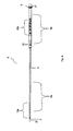
- Figure 1 is a perspective view according to an embodiment of the measuring device.
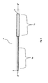
- Figure 2 is a side view according to an embodiment of the measuring device.
- Figure 3 is a side view according to an embodiment of the measuring device.
- Figure 4 is a detail view of the solid member according to an embodiment of the measuring device.
- Figure 5 is a cross-sectional detail view of the cannulated member according to an embodiment of the measuring device.
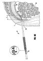
- Figure 6 is a schematic that shows an embodiment of the measuring device in use where the tissue is a rotator cuff.
- measuring device 10 measures the depth t of a tear of a tissue 150 from its point of attachment 152, shown in Figure 6 as a rotator cuff. In an embodiment, the measuring device 10 also measures the thickness T of the tissue 150. See, e.g., Figure 6C .
- the measuring device 10 is optionally used arthroscopically which can provide access and magnification. As shown in the figures, measuring device 10 comprises a member 5 and a cannulated member 1 into which the member 5 is disposed. In an example, member 5 slides within cannulated member 1. In an example, member 5 is solid.
- the measuring device 10 is made of stainless steel, titanium, or other metals, or Polyaryletheretherketone (PEEK) or other hard plastics.
- the measuring device 10 is of a length and diameter appropriate for ease of handling and sufficient to extend the depth t of a tear and thickness T of the tissue 50.
- member 5 has a shaft 6 and a distal tip 7 configured to penetrate through a tear in a tissue (not shown).
- the distal tip 7 is beveled to facilitate penetration of the tissue 50, including ligament, muscle, tendon or the like.
- Shaft 6 has distal and proximal portions 6a, 6b.
- the distal portion 6a of the shaft 6 has an outer diameter D 1 that is less than an outer diameter D 2 of the proximal portion 6b of the shaft 6.
- measuring device 10 further comprises a head 8 disposed on the member 5 at an end of the shaft 6 opposite the distal tip 7.
- Head 8 has a diameter that is greater than the outer diameter of the proximal portion 1b of cannulated member 1.
- the shaft 6 of the member 5 is configured with an indentation to receive a seal 20 such as an O-ring that stabilizes the member 5 within the cannulated member 1 or to seal member 5 from cannulated member 1.
- the distal portion 6a of the shaft 6 has an outer diameter D 1 of about 0.05 inches to about 0.08 inches, and preferably about 0.06 inches
- the proximal portion 6b of the shaft 6 has an outer diameter D 2 of about 0.101 inches to about 0.169 inches, and preferably about 0.135 inches.
- distal tip 7 has an angle ⁇ of about 30° to about 50°, and preferably of about 40°.
- the plurality of indicia 15 comprises a first plurality of indicia 15a disposed on the distal portion 6a of the shaft 6 and a second plurality of indicia 15b disposed on the proximal portion 6b of the shaft 6.
- First plurality of indicia 15a measures the depth t of the tear of the tissue 50
- second plurality of indicia 15b measures a total thickness T of the tissue 50.
- the function of the plurality of indicia 15 is explained in more detail below.
- head 8 contacts proximal end 2 of cannulated member 1 when member 5 is maximally extended.
- cannulated member 1 has a distal portion 1a and a proximal portion 1b.
- the distal portion 1a of the cannulated member 1 has an outer diameter d 1 that is less than an outer diameter d 2 of the proximal portion 1b of the cannulated member 1.
- cannulated member 1 optionally further comprises a grip 9, as shown in the examples in Figures 1 and 3 .
- cannulated member 1 further comprises a window 11 positioned to view at least a portion of the plurality of indicia 15 disposed on the shaft 6.
- Figure 3 shows the window 11 positioned to view a portion of the plurality of indicia 15b disposed on the proximal portion 6b of the shaft 6.
- the cannulated member 1 comprises a trocar (not shown) to facilitate introduction of the device 10 into the tissue.
- the distal portion 1a of the cannulated member 1 has an inner diameter d 1 of about 0.053 inches to about 0.089 inches, and preferably about 0.071 inches
- the proximal portion 1b of the cannulated member 1 has an inner diameter d 2 of about 0.113 inches to about 0.188 inches, and preferably about 0.150 inches.
- a method of performing orthopedic surgery comprising the steps of using the measuring device 10 to measure the depth t of a tissue tear, such as tears of a ligament, tendon, muscle, or the like, including the distance from the point of attachment 152 (shown in Figure 6 as the humeral head) from which the tissue 150 (shown as the rotator cuff) has torn.
- the measuring device 10 may be used in surgeries to repair tears of the rotator cuff 150, such as partial articular surface tendon avulsion (PASTA) tears.
- the measurement device 10 is positioned substantially tangential to the tear by way of arthroscopic or open surgical means.
- the measurement device 10 is positioned by penetrating the distal tip 7 through the tear, such as by using a stab incision.
- a first step of measuring a tear of a tissue 150 using the measuring device 10 member 5 is slid within the cannulated member 1 so that the distal tip 7 of member 5 is substantially positioned at a distal margin 153 (shown in Figure 6 as the articular margin). In this position, at least a portion of a plurality of indicia 15 is exposed on the shaft 6 of member 5, such as the first plurality of indicia 15a exposed on the distal portion 6a of the shaft depicted in Figures 6A , 6C .
- the step of sliding the member 5 within the cannulated member 1 to position the distal tip 7 at the distal margin 153 is performed while viewing the tissue intraarticularly.
- cannulated member 1 is moved so that the distal end 1a of the cannulated member 1 is substantially positioned at a proximal margin 154 (shown in Figure 6 as the bursal side) while substantially maintaining the position of the distal tip 7 of member 5 at the distal margin 53 (see Figure 6B ).
- a proximal margin 154 shown in Figure 6 as the bursal side
- at least a portion of a plurality of indicia 15 is exposed on the shaft 6 of member 5, such as the second plurality of indicia 15b exposed on the proximal portion 6b of the shaft depicted in Figure 6C .
- the step of moving the cannulated member 1 to the proximal margin 154 is performed while viewing the tissue from a subacromial viewing position.
- the plurality of indicia 15 are read.
- the depth t of the tear in the tissue 150 is measured using the first plurality of indicia 15a and is equal to the size of the distal portion 6a of the shaft 6 that is exposed between the distal tip 7 positioned at the distal margin 153 and the distal edge of the tissue tear, as shown in Figure 6 .
- the depth t is measured by counting the number of indicia exposed.
- the depth of the tear t of the rotator cuff tendon 150 is equal to the size of the distal portion 6a of shaft 6 that is exposed between distal tip 7 positioned at articular margin 153 and the distal edge of the tear 155.
- three indicia are exposed, the indicia appearing in 3 mm increments, so the depth t of the tear is 9 mm. In other examples, the indicia are positioned at other increments.
- the total thickness of the tissue T is measured using the second plurality of indicia 15b and is reflected by the indicia at which the proximal end 2 of cannulated member 1 is substantially positioned.
- the indicia appear in 5 mm increments and as shown in Figure 6C , the total thickness T of the rotator cuff tendon 150 is 14 mm.
- the method of measuring further comprises the step of calculating a percent of the tear in the tissue.
- the step of calculating is performed according to the following formula: deph of the tear of tissue t / thickness of the tissue T * 100.
- the percentage of the tissue that is torn is used to decide whether to surgically repair the tear in the tissue.
- the method further comprises the step of surgically repairing the tear when the percentage of the tear is greater than about 50%.
Landscapes
- Health & Medical Sciences (AREA)
- Life Sciences & Earth Sciences (AREA)
- Medical Informatics (AREA)
- Molecular Biology (AREA)
- Oral & Maxillofacial Surgery (AREA)
- Biophysics (AREA)
- Pathology (AREA)
- Engineering & Computer Science (AREA)
- Biomedical Technology (AREA)
- Heart & Thoracic Surgery (AREA)
- Dentistry (AREA)
- Physics & Mathematics (AREA)
- Surgery (AREA)
- Animal Behavior & Ethology (AREA)
- General Health & Medical Sciences (AREA)
- Public Health (AREA)
- Veterinary Medicine (AREA)
- Orthopedic Medicine & Surgery (AREA)
- Rheumatology (AREA)
- Surgical Instruments (AREA)
- Measurement Of The Respiration, Hearing Ability, Form, And Blood Characteristics Of Living Organisms (AREA)
Abstract
Description
- Rotator cuff tears are a common source of shoulder pain and result from tendon degeneration or sports-related injury or other trauma. Partial thickness defects of the rotator cuff result when the tendon is incompletely detached from the humeral head. One method of treatment for rotator cuff tears is a surgical procedure to reattach the tendon to the humeral head from where it is torn. In the case of partial tears, treatment options include non-surgical procedures such as physical therapy and/or a surgical procedure in which the tendon is completely detached from the humeral head, followed by reattachment of the tendon thereto. The size or depth of the tear is an important factor that is considered when determining the appropriate treatment for a partial tear of the rotator cuff, with surgery being the generally preferred treatment when more than 50 percent of the tendon is torn from the humeral head and non-surgical options being generally preferred when less than 50 percent of the tendon is torn from the humeral head.
- In an embodiment, a measuring device for measuring a depth of a tear of a tissue is disclosed. The measuring device comprises: a member having a shaft and a distal tip, there being a plurality of indicia on the shaft of the member for measuring the tissue tear; and a cannulated member into which the member is disposed. In an example, the member is solid. In another example, the plurality of indicia comprises a first plurality of indicia disposed on a distal portion of the shaft and a second plurality of indicia disposed on a proximal portion of the shaft. In an example, the tissue is a rotator cuff tendon.
- In another embodiment, a method of measuring a tear of a tissue using the measuring device is disclosed. The method of measuring comprises the steps of: sliding the member within the cannulated member so that the distal tip of the member is substantially positioned at a distal margin, wherein the measuring device is positioned substantially tangential to the tear; moving the cannulated member so that a distal end of the cannulated member is substantially at a proximal margin while substantially maintaining the position of the distal tip of the member at the distal margin; and reading the indicia. In an example, the first plurality of indicia is read to measure a depth of the tear of the tissue and the second plurality of indicia is read to measure a thickness of the tissue. In an example, the depth of the tear of the tissue and the thickness of the tissue are used to calculate the percentage of the tissue that is torn and to decide whether to surgically repair the tear.
- Other advantages of the present invention will become apparent from a perusal of the following detailed description of presently preferred embodiments taken together with the accompanying drawings.
-
Figure 1 is a perspective view according to an embodiment of the measuring device. -
Figure 2 is a side view according to an embodiment of the measuring device. -
Figure 3 is a side view according to an embodiment of the measuring device. -
Figure 4 is a detail view of the solid member according to an embodiment of the measuring device. -
Figure 5 is a cross-sectional detail view of the cannulated member according to an embodiment of the measuring device. -
Figure 6 is a schematic that shows an embodiment of the measuring device in use where the tissue is a rotator cuff. - Referring initially to
Figures 1-3 , an embodiment of themeasuring device 10 is shown. Themeasuring device 10 measures the depth t of a tear of atissue 150 from its point ofattachment 152, shown inFigure 6 as a rotator cuff. In an embodiment, themeasuring device 10 also measures the thickness T of thetissue 150. See, e.g.,Figure 6C . Themeasuring device 10 is optionally used arthroscopically which can provide access and magnification. As shown in the figures, measuringdevice 10 comprises amember 5 and acannulated member 1 into which themember 5 is disposed. In an example,member 5 slides withincannulated member 1. In an example,member 5 is solid. In examples, themeasuring device 10 is made of stainless steel, titanium, or other metals, or Polyaryletheretherketone (PEEK) or other hard plastics. Themeasuring device 10 is of a length and diameter appropriate for ease of handling and sufficient to extend the depth t of a tear and thickness T of the tissue 50. - As shown in detail in
Figure 4 ,member 5 has ashaft 6 and adistal tip 7 configured to penetrate through a tear in a tissue (not shown). In an example, thedistal tip 7 is beveled to facilitate penetration of the tissue 50, including ligament, muscle, tendon or the like. Shaft 6 has distal andproximal portions distal portion 6a of theshaft 6 has an outer diameter D1 that is less than an outer diameter D2 of theproximal portion 6b of theshaft 6. As shown generally in the figures, in an example, measuringdevice 10 further comprises ahead 8 disposed on themember 5 at an end of theshaft 6 opposite thedistal tip 7.Head 8 has a diameter that is greater than the outer diameter of theproximal portion 1b of cannulatedmember 1. Optionally, and as shown inFigure 4 , theshaft 6 of themember 5 is configured with an indentation to receive aseal 20 such as an O-ring that stabilizes themember 5 within thecannulated member 1 or to sealmember 5 fromcannulated member 1. - In examples, the
distal portion 6a of theshaft 6 has an outer diameter D 1 of about 0.05 inches to about 0.08 inches, and preferably about 0.06 inches, and theproximal portion 6b of theshaft 6 has an outer diameter D 2 of about 0.101 inches to about 0.169 inches, and preferably about 0.135 inches. In an example such as illustrated inFigure 2 ,distal tip 7 has an angle α of about 30° to about 50°, and preferably of about 40°. - As shown generally in the figures, there is a plurality of indicia 15 on the
shaft 6 ofmember 5 for measuring the depth t of a tear of a tissue 50 or the distance from the bone from which the tissue has torn, such as measuring the depth t in millimeters. In the example shown inFigure 4 , the plurality of indicia 15 comprises a first plurality ofindicia 15a disposed on thedistal portion 6a of theshaft 6 and a second plurality ofindicia 15b disposed on theproximal portion 6b of theshaft 6. First plurality ofindicia 15a measures the depth t of the tear of the tissue 50 and second plurality ofindicia 15b measures a total thickness T of the tissue 50. The function of the plurality of indicia 15 is explained in more detail below. In use,head 8 contactsproximal end 2 ofcannulated member 1 whenmember 5 is maximally extended. - As shown in detail in
Figure 5 ,cannulated member 1 has adistal portion 1a and aproximal portion 1b. In an example, thedistal portion 1a of thecannulated member 1 has an outer diameter d1 that is less than an outer diameter d2 of theproximal portion 1b of thecannulated member 1. In an example,cannulated member 1 optionally further comprises a grip 9, as shown in the examples inFigures 1 and 3 . In another example,cannulated member 1 further comprises a window 11 positioned to view at least a portion of the plurality of indicia 15 disposed on theshaft 6.Figure 3 shows the window 11 positioned to view a portion of the plurality ofindicia 15b disposed on theproximal portion 6b of theshaft 6. In an example, thecannulated member 1 comprises a trocar (not shown) to facilitate introduction of thedevice 10 into the tissue. - In examples, the
distal portion 1a of thecannulated member 1 has an inner diameter d1 of about 0.053 inches to about 0.089 inches, and preferably about 0.071 inches, and theproximal portion 1b of thecannulated member 1 has an inner diameter d2 of about 0.113 inches to about 0.188 inches, and preferably about 0.150 inches. - In another embodiment, a method of performing orthopedic surgery is disclosed, the method comprising the steps of using the
measuring device 10 to measure the depth t of a tissue tear, such as tears of a ligament, tendon, muscle, or the like, including the distance from the point of attachment 152 (shown inFigure 6 as the humeral head) from which the tissue 150 (shown as the rotator cuff) has torn. In examples, themeasuring device 10 may be used in surgeries to repair tears of therotator cuff 150, such as partial articular surface tendon avulsion (PASTA) tears. In examples, themeasurement device 10 is positioned substantially tangential to the tear by way of arthroscopic or open surgical means. Optionally, themeasurement device 10 is positioned by penetrating thedistal tip 7 through the tear, such as by using a stab incision. - In a first step of measuring a tear of a
tissue 150 using themeasuring device 10,member 5 is slid within thecannulated member 1 so that thedistal tip 7 ofmember 5 is substantially positioned at a distal margin 153 (shown inFigure 6 as the articular margin). In this position, at least a portion of a plurality of indicia 15 is exposed on theshaft 6 ofmember 5, such as the first plurality ofindicia 15a exposed on thedistal portion 6a of the shaft depicted inFigures 6A ,6C . In an example, the step of sliding themember 5 within thecannulated member 1 to position thedistal tip 7 at thedistal margin 153 is performed while viewing the tissue intraarticularly. - In a next step,
cannulated member 1 is moved so that thedistal end 1a of thecannulated member 1 is substantially positioned at a proximal margin 154 (shown inFigure 6 as the bursal side) while substantially maintaining the position of thedistal tip 7 ofmember 5 at the distal margin 53 (seeFigure 6B ). In this position, at least a portion of a plurality of indicia 15 is exposed on theshaft 6 ofmember 5, such as the second plurality ofindicia 15b exposed on theproximal portion 6b of the shaft depicted inFigure 6C . In an example, the step of moving the cannulatedmember 1 to theproximal margin 154 is performed while viewing the tissue from a subacromial viewing position. - In a next step, the plurality of indicia 15 are read. The depth t of the tear in the
tissue 150 is measured using the first plurality ofindicia 15a and is equal to the size of thedistal portion 6a of theshaft 6 that is exposed between thedistal tip 7 positioned at thedistal margin 153 and the distal edge of the tissue tear, as shown inFigure 6 . In an example, the depth t is measured by counting the number of indicia exposed. In the example shown inFigure 6A , the depth of the tear t of therotator cuff tendon 150 is equal to the size of thedistal portion 6a ofshaft 6 that is exposed betweendistal tip 7 positioned atarticular margin 153 and the distal edge of the tear 155. InFigure 6A , three indicia are exposed, the indicia appearing in 3 mm increments, so the depth t of the tear is 9 mm. In other examples, the indicia are positioned at other increments. - The total thickness of the tissue T is measured using the second plurality of
indicia 15b and is reflected by the indicia at which theproximal end 2 of cannulatedmember 1 is substantially positioned. In the example shown in Figure 7, the indicia appear in 5 mm increments and as shown inFigure 6C , the total thickness T of therotator cuff tendon 150 is 14 mm. - In an example, the method of measuring further comprises the step of calculating a percent of the tear in the tissue. The step of calculating is performed according to the following formula:

In the example shown schematically in the panels of Figure 7, the percentage of the tear is:
Optionally, the percentage of the tissue that is torn, as determined by the relationship between the depth t of the tear and the thickness T of the tissue, is used to decide whether to surgically repair the tear in the tissue. In an example where the torn tissue is a rotator cuff tendon, the method further comprises the step of surgically repairing the tear when the percentage of the tear is greater than about 50%. - While the foregoing has been set forth in considerable detail, it is to be understood that the drawings, detailed embodiments, and examples are presented for elucidation and not limitation. Design variations, especially in matters of shape, size, and arrangements of parts, may be made but are within the principles of the invention. Those skilled in the art will realize that such changes or modifications of the invention or combinations of elements, variations, equivalents, or improvements therein are still within the scope of the invention as defined in the appended claims.
Claims (19)
- A measuring device for measuring a depth of a tear of a tissue, the measuring device comprising:a member having a shaft and a distal tip, there being a plurality of indicia on the shaft of the member for measuring the depth of the tear; anda cannulated member into which the member is disposed.
- The measuring device as in claim 1 wherein the device is used to measure the depth arthroscopically.
- The measuring device as in claim 1 wherein the plurality of indicia comprises a first plurality of indicia disposed on a distal portion of the shaft that measures the depth of the tear; and a second plurality of indicia disposed on a proximal portion of the shaft that measures a total thickness of the tissue.
- The measuring device as in claim 1 wherein the distal tip is configured to penetrate through the tear.
- The measuring device as in claim 1 wherein the cannulated member further comprises a window positioned on the cannulated member to view at least a portion of the plurality of indicia.
- A measuring device for measuring a depth of a tear of a tissue, the measuring device comprising:a cannulated member having a distal portion and a proximal portion;a solid member slidably disposed within the cannulated member and having a shaft and a distal tip, the shaft having distal and proximal portions;a first plurality of indicia disposed on the distal portion of the shaft; anda second plurality of indicia disposed on the proximal portion of the shaft.
- The measuring device as in claim 6 further comprising a head disposed on the solid member at an end of the shaft opposite the distal tip.
- The measuring device as in claim 6 wherein the cannulated member further comprises a grip.
- The measuring device of claim 6 wherein the distal tip is configured to penetrate through the tear in the tissue.
- The measuring device of claim 6 wherein the first plurality of indicia measures a depth of the tear and wherein the second plurality of indicia measures a total thickness of the tissue.
- The measuring device as in claim 6 further comprising a seal positioned on the shaft of the solid member that stabilizes the solid member within the cannulated member.
- The measuring device as in claim 6 wherein the tissue is a rotator cuff tendon.
- The measuring device as in claim 6 wherein the device is made from at least one of stainless steel, titanium, PEEK, or a hard plastic.
- The measuring device as in claim 6 wherein the cannulated member further comprises a window positioned to view at least a portion of the plurality of indicia disposed on the proximal portion of the shaft.
- A method of measuring a tear of a tissue using a measuring device, the measuring device having a member having a shaft and a distal tip, there being a plurality of indicia on the shaft of the member for measuring the tissue tear, and a cannulated member into which the member is disposed, the method of measuring comprising the steps ofa. sliding the member within the cannulated member so that the distal tip of the member is substantially positioned at a distal margin, wherein the measuring device is positioned substantially tangential to the tear;b. moving the cannulated member so that a distal end of the cannulated member is substantially at a proximal margin while substantially maintaining the position of the distal tip of the solid member at the distal margin;c. reading the plurality of indicia.
- The method of measuring as in claim 15 further comprising the step of calculating a percent of the tear of the tissue, wherein the step of calculating is performed according to the following formula:(a depth of the tear of the tissue / a thickness of the tissue) * 100.
- The method of measuring as in claim 15 wherein the steps are performed arthroscopically.
- The method of measuring as in claim 15 wherein the tissue is a rotator cuff tendon, and wherein the steps are performed arthroscopically, the solid member being slid within the cannulated member so that the distal tip is substantially positioned at an articular margin, and the cannulated member being moved so that the distal end is substantially at a bursal side of the rotator cuff tendon.
- The method of measuring as in claim 15 further comprising the step of using length of the tear in the tissue and the thickness of the tissue to decide whether to surgically repair the tear.
Applications Claiming Priority (1)
| Application Number | Priority Date | Filing Date | Title |
|---|---|---|---|
| US86894706P | 2006-12-07 | 2006-12-07 |
Publications (2)
| Publication Number | Publication Date |
|---|---|
| EP1929945A2 true EP1929945A2 (en) | 2008-06-11 |
| EP1929945A3 EP1929945A3 (en) | 2009-01-14 |
Family
ID=39158512
Family Applications (1)
| Application Number | Title | Priority Date | Filing Date |
|---|---|---|---|
| EP07254740A Ceased EP1929945A3 (en) | 2006-12-07 | 2007-12-07 | Measuring device |
Country Status (2)
| Country | Link |
|---|---|
| US (1) | US8308662B2 (en) |
| EP (1) | EP1929945A3 (en) |
Families Citing this family (67)
| Publication number | Priority date | Publication date | Assignee | Title |
|---|---|---|---|---|
| US8177841B2 (en) | 2000-05-01 | 2012-05-15 | Arthrosurface Inc. | System and method for joint resurface repair |
| EP2314257B9 (en) | 2000-05-01 | 2013-02-27 | ArthroSurface, Inc. | System for joint resurface repair |
| US6610067B2 (en) | 2000-05-01 | 2003-08-26 | Arthrosurface, Incorporated | System and method for joint resurface repair |
| US7163541B2 (en) | 2002-12-03 | 2007-01-16 | Arthrosurface Incorporated | Tibial resurfacing system |
| US7678151B2 (en) | 2000-05-01 | 2010-03-16 | Ek Steven W | System and method for joint resurface repair |
| US7914545B2 (en) | 2002-12-03 | 2011-03-29 | Arthrosurface, Inc | System and method for retrograde procedure |
| US7901408B2 (en) | 2002-12-03 | 2011-03-08 | Arthrosurface, Inc. | System and method for retrograde procedure |
| US8388624B2 (en) | 2003-02-24 | 2013-03-05 | Arthrosurface Incorporated | Trochlear resurfacing system and method |
| WO2005051231A2 (en) | 2003-11-20 | 2005-06-09 | Arthrosurface, Inc. | Retrograde delivery of resurfacing devices |
| JP2008504107A (en) | 2004-06-28 | 2008-02-14 | アースロサーフィス・インコーポレーテッド | Joint surface replacement system |
| EP1807007A4 (en) * | 2004-10-29 | 2014-03-19 | Depuy Products Inc | Coordinate instrument set |
| US7828853B2 (en) | 2004-11-22 | 2010-11-09 | Arthrosurface, Inc. | Articular surface implant and delivery system |
| CA2623106C (en) | 2005-09-19 | 2013-12-24 | Histogenics Corporation | Cell-support matrix having narrowly defined uniformly vertically and non-randomly organized porosity and pore density and a method for preparation thereof |
| US7559150B2 (en) * | 2005-10-13 | 2009-07-14 | Synthes Usa, Llc | Depth gauge |
| AU2007332787A1 (en) | 2006-12-11 | 2008-06-19 | Arthrosurface Incorporated | Retrograde resection apparatus and method |
| US20090005786A1 (en) * | 2007-06-28 | 2009-01-01 | Stryker Trauma Gmbh | Bone hole measuring device |
| WO2009111481A1 (en) | 2008-03-03 | 2009-09-11 | Arthrosurface Incorporated | Bone resurfacing system and method |
| EP2257240B1 (en) * | 2008-03-04 | 2017-01-18 | Smith & Nephew, Inc. | A device for use during ligament reconstruction surgery |
| WO2010081029A1 (en) | 2009-01-08 | 2010-07-15 | Rotation Medical, Inc. | Implantable tendon protection systems and related kits and methods |
| US9179910B2 (en) | 2009-03-20 | 2015-11-10 | Rotation Medical, Inc. | Medical device delivery system and method |
| CA3064646C (en) | 2009-04-17 | 2023-01-03 | Arthrosurface Incorporated | Glenoid resurfacing system and method |
| WO2010121250A1 (en) | 2009-04-17 | 2010-10-21 | Arthrosurface Incorporated | Glenoid resurfacing system and method |
| US10945743B2 (en) | 2009-04-17 | 2021-03-16 | Arthrosurface Incorporated | Glenoid repair system and methods of use thereof |
| JP5718912B2 (en) | 2009-06-04 | 2015-05-13 | ローテーション メディカル インコーポレイテッドRotation Medical,Inc. | Implant delivery system and method for preparing the delivery system |
| US12471975B2 (en) | 2009-06-04 | 2025-11-18 | Rotation Medical, Inc. | Methods and apparatus for deploying sheet-like materials |
| JP5662427B2 (en) | 2009-06-04 | 2015-01-28 | ローテーション メディカル インコーポレイテッドRotation Medical,Inc. | Device for fixing a sheet-like material to a target tissue |
| US8690887B2 (en) * | 2010-02-08 | 2014-04-08 | Jeffrey B. Kleiner | Method and system for identification of a center of a vertebral disc space and corresponding central axis of a spinal column |
| US9808320B2 (en) | 2010-02-08 | 2017-11-07 | Jeffrey B. Kleiner | Method and system for identification of a center of a patient's body part |
| BR112012022482A2 (en) | 2010-03-05 | 2016-07-19 | Arthrosurface Inc | tibial surface recomposition system and method. |
| US9198750B2 (en) | 2010-03-11 | 2015-12-01 | Rotation Medical, Inc. | Tendon repair implant and method of arthroscopic implantation |
| AU2011227190B2 (en) | 2010-03-18 | 2016-04-14 | Smith & Nephew, Inc. | A device for use during ligament reconstruction surgery |
| US8864687B2 (en) * | 2010-09-17 | 2014-10-21 | Thomas C. May | Method and apparatus for restoring articular cartilage |
| CA2825918C (en) | 2011-02-15 | 2018-08-07 | Rotation Medical, Inc. | Methods and apparatus for delivering and positioning sheet-like materials |
| WO2012145059A1 (en) | 2011-02-15 | 2012-10-26 | Rotation Medical, Inc. | Methods and apparatus for fixing sheet-like materials to a target tissue |
| US9066716B2 (en) | 2011-03-30 | 2015-06-30 | Arthrosurface Incorporated | Suture coil and suture sheath for tissue repair |
| US9107661B2 (en) | 2011-12-19 | 2015-08-18 | Rotation Medical, Inc. | Fasteners and fastener delivery devices for affixing sheet-like materials to bone or tissue |
| US9370356B2 (en) | 2011-12-19 | 2016-06-21 | Rotation Medical, Inc. | Fasteners and fastener delivery devices for affixing sheet-like materials to bone or tissue |
| AU2012355433B2 (en) | 2011-12-19 | 2016-10-20 | Rotation Medical, Inc. | Apparatus and method for forming pilot holes in bone and delivering fasteners therein for retaining an implant |
| WO2013096224A1 (en) | 2011-12-19 | 2013-06-27 | Rotation Medical, Inc. | Fasteners for affixing sheet -like materials to bone or tissue |
| EP2804565B1 (en) | 2011-12-22 | 2018-03-07 | Arthrosurface Incorporated | System for bone fixation |
| WO2013101640A1 (en) | 2011-12-29 | 2013-07-04 | Rotation Medical, Inc. | Guidewire having a distal fixation member for delivering and positioning sheet-like materials in surgery |
| EP2797532B1 (en) | 2011-12-29 | 2016-04-06 | Rotation Medical, Inc. | Apparatus for delivering and positioning sheet-like materials in surgery |
| WO2013101641A2 (en) | 2011-12-29 | 2013-07-04 | Rotation Medical, Inc. | Anatomical location markers and methods of use in positioning sheet-like materials during surgery |
| EP2797506B1 (en) | 2011-12-30 | 2016-07-27 | Synthes GmbH | Round depth gauge |
| JP2013172803A (en) * | 2012-02-24 | 2013-09-05 | Masanori Saeki | Pharmaceutical formulation injecting implement |
| DE112013003358T5 (en) | 2012-07-03 | 2015-03-19 | Arthrosurface, Inc. | System and procedure for joint surface replacement and repair |
| US9271801B2 (en) * | 2013-03-13 | 2016-03-01 | Medos International Sarl | Methods, systems, and devices for gauging a bone tunnel |
| US9492200B2 (en) | 2013-04-16 | 2016-11-15 | Arthrosurface Incorporated | Suture system and method |
| US10624748B2 (en) | 2014-03-07 | 2020-04-21 | Arthrosurface Incorporated | System and method for repairing articular surfaces |
| US11607319B2 (en) | 2014-03-07 | 2023-03-21 | Arthrosurface Incorporated | System and method for repairing articular surfaces |
| US9931219B2 (en) | 2014-03-07 | 2018-04-03 | Arthrosurface Incorporated | Implant and anchor assembly |
| CA2945821C (en) | 2014-05-09 | 2018-09-04 | Rotation Medical, Inc. | Medical implant delivery system for sheet-like implant |
| EP4275620A3 (en) | 2014-11-04 | 2024-01-17 | Rotation Medical, Inc. | Medical implant delivery system |
| US10675019B2 (en) | 2014-11-04 | 2020-06-09 | Rotation Medical, Inc. | Medical implant delivery system and related methods |
| EP3215025B1 (en) | 2014-11-04 | 2020-12-23 | Rotation Medical, Inc. | Medical implant delivery system |
| US10077420B2 (en) | 2014-12-02 | 2018-09-18 | Histogenics Corporation | Cell and tissue culture container |
| US11147504B2 (en) * | 2015-04-27 | 2021-10-19 | Osaka Sangyo University | Examination diagnosis device |
| US10898228B2 (en) | 2015-05-06 | 2021-01-26 | Rotation Medical, Inc. | Medical implant delivery system and related methods |
| WO2016205186A1 (en) | 2015-06-15 | 2016-12-22 | Rotation Medical, Inc. | Tendon repair implant and method of implantation |
| CA3008670A1 (en) | 2015-12-31 | 2017-07-06 | Rotation Medical, Inc. | Fastener delivery system and related methods |
| US10314689B2 (en) | 2015-12-31 | 2019-06-11 | Rotation Medical, Inc. | Medical implant delivery system and related methods |
| US11602407B2 (en) | 2016-09-08 | 2023-03-14 | Ascension Texas | Depth gauges and related methods |
| JP2020527964A (en) * | 2017-07-05 | 2020-09-17 | シルク・ロード・メディカル・インコーポレイテッドSilk Road Medical, Inc. | Transcarotid access methods and devices |
| CA3108761A1 (en) | 2017-08-04 | 2019-02-07 | Arthrosurface Incorporated | Multicomponent articular surface implant |
| EP3687415B1 (en) | 2017-09-28 | 2023-07-19 | C. R. Bard, Inc. | Catheter with movable indicator |
| EP3720385B1 (en) | 2017-12-07 | 2023-09-27 | Rotation Medical, Inc. | Medical implant delivery system |
| GB2609338B (en) | 2019-03-12 | 2023-06-14 | Arthrosurface Inc | Humeral and glenoid articular surface implant systems and methods |
Family Cites Families (38)
| Publication number | Priority date | Publication date | Assignee | Title |
|---|---|---|---|---|
| US2763935A (en) * | 1954-06-11 | 1956-09-25 | Purdne Res Foundation | Determining depth of layers of fat and of muscle on an animal body |
| US3478435A (en) * | 1968-03-11 | 1969-11-18 | Edmond A Cook | Depth gauge for measuring the thickness of animal tissues |
| US4450834A (en) * | 1979-10-18 | 1984-05-29 | Ace Orthopedic Manufacturing, Inc. | External fixation device |
| CA1221596A (en) * | 1984-03-09 | 1987-05-12 | David Evans | Surgical needle |
| SE457052B (en) * | 1986-03-12 | 1988-11-28 | Jan Gillquist | INSTRUMENTS FOR MEASUREMENT OF DISTANCE BETWEEN BENDLES IN A KNEE JOINT |
| GB2209673B (en) * | 1987-09-15 | 1991-06-12 | Wallace Ltd H G | Catheter and cannula assembly |
| US5010892A (en) * | 1988-05-04 | 1991-04-30 | Triangle Research And Development Corp. | Body lumen measuring instrument |
| US5180388A (en) * | 1990-06-28 | 1993-01-19 | American Cyanamid Company | Bone pinning system |
| US5013318A (en) * | 1990-07-31 | 1991-05-07 | Special Devices Incorporated | Medical instrument for measuring depth of fastener hold in bone |
| US6224608B1 (en) * | 1990-08-10 | 2001-05-01 | United States Surgical Corporation | Tissue holding device and method |
| US5171248A (en) * | 1991-02-27 | 1992-12-15 | Intermedics Orthopedics, Inc. | Medullary caliper |
| DE4229873C1 (en) * | 1992-09-04 | 1994-03-24 | Ethicon Gmbh | Endoscopic test-seal for guide - has guide formed of sleeve with holed flange at proximal end distal end is capable of being cut to desired length |
| US5292309A (en) * | 1993-01-22 | 1994-03-08 | Schneider (Usa) Inc. | Surgical depth measuring instrument and method |
| US5320608A (en) * | 1993-01-29 | 1994-06-14 | Gerrone Carmen J | Combined pneumo-needle and trocar apparatus |
| US5312351A (en) * | 1993-01-29 | 1994-05-17 | Gerrone Carmen J | Combined pneumo-needle and trocar apparatus |
| EP0723786A1 (en) * | 1995-01-30 | 1996-07-31 | Cardiovascular Concepts, Inc. | Lesion measurement catheter and method |
| US5895389A (en) * | 1997-05-29 | 1999-04-20 | Synthes (U.S.A.) | Drilling guide and measuring instrumentation |
| US6039753A (en) * | 1998-07-16 | 2000-03-21 | Meislin; Robert | Single unit surgical fastener and method |
| US6427351B1 (en) * | 1998-12-28 | 2002-08-06 | Depuy Orthopaedics, Inc. | Arthroscopic measuring device |
| US6159179A (en) * | 1999-03-12 | 2000-12-12 | Simonson; Robert E. | Cannula and sizing and insertion method |
| US6159167A (en) * | 1999-04-12 | 2000-12-12 | Hardin-Naser; Juel E. | Disposable wound measuring device and method |
| DE60042705D1 (en) * | 2000-07-13 | 2009-09-17 | Wilson Cook Medical Inc | MARKING SYSTEM FOR MEDICAL INSTRUMENT |
| US6893421B1 (en) * | 2000-08-08 | 2005-05-17 | Scimed Life Systems, Inc. | Catheter shaft assembly |
| GB2371868B (en) * | 2001-01-31 | 2003-12-03 | Precimed Sa | Flexible measurement device |
| US6524259B2 (en) * | 2001-06-08 | 2003-02-25 | Cervilenz, Inc. | Devices and methods for cervix measurement |
| ES2307738T3 (en) * | 2002-02-07 | 2008-12-01 | Synthes Gmbh | DEVICE FOR MEASURING THE LENGTH AND DEPTH THAT CAN BE USED IN SURGERY. |
| US7166112B2 (en) * | 2002-03-25 | 2007-01-23 | Depuy Spine, Inc. | Device for determining distance between two points in a surgical site |
| US6764453B2 (en) * | 2002-05-08 | 2004-07-20 | Sherwood Services Ag | Stoma measuring device |
| US7364567B2 (en) * | 2002-06-10 | 2008-04-29 | Abbott Cardiovascular Systems Inc. | Systems and methods for detecting tissue contact and needle penetration depth |
| US20040068190A1 (en) | 2002-10-04 | 2004-04-08 | Cespedes Eduardo Ignacio | Imaging catheter with indicia and methods of use |
| US20040089190A1 (en) * | 2002-11-08 | 2004-05-13 | Krishnan Ramu | Transportation system with linear switched reluctance actuator for propulsion and levitation |
| US7527631B2 (en) * | 2003-03-31 | 2009-05-05 | Depuy Products, Inc. | Arthroplasty sizing gauge |
| US7468041B2 (en) * | 2003-06-26 | 2008-12-23 | Depuy Products, Inc. | Modular surgical instrument with reciprocable implement |
| WO2005027745A1 (en) | 2003-09-23 | 2005-03-31 | Synthes Ag Chur | Device for measuring length and depth |
| US20050137600A1 (en) * | 2003-12-23 | 2005-06-23 | Jacobs Andrew M. | Articular cartilage repair implant delivery device and method of use |
| US7678077B2 (en) * | 2004-02-20 | 2010-03-16 | Boston Scientific Scimed, Inc. | Variable depth injection device and method |
| US7165336B2 (en) * | 2005-03-16 | 2007-01-23 | Eidosmed Llc | Surgical depth instrument |
| US20060224161A1 (en) * | 2005-04-01 | 2006-10-05 | The General Hospital Corporation | Depth gauge apparatus and methods |
-
2007
- 2007-12-07 US US11/952,169 patent/US8308662B2/en active Active
- 2007-12-07 EP EP07254740A patent/EP1929945A3/en not_active Ceased
Also Published As
| Publication number | Publication date |
|---|---|
| US8308662B2 (en) | 2012-11-13 |
| EP1929945A3 (en) | 2009-01-14 |
| US20080306408A1 (en) | 2008-12-11 |
Similar Documents
| Publication | Publication Date | Title |
|---|---|---|
| US8308662B2 (en) | Measuring device | |
| US9198676B2 (en) | PCL guides for drilling tibial and femoral tunnels | |
| US7857851B2 (en) | Implant system with sizing templates | |
| US8409250B2 (en) | Meniscal repair system and method | |
| US9271801B2 (en) | Methods, systems, and devices for gauging a bone tunnel | |
| EP1836970B2 (en) | Marked suture | |
| US9113954B2 (en) | Coordinate instrument set | |
| Detrisac et al. | Arthroscopic shoulder capsulorrhaphy using metal staples | |
| US8795284B2 (en) | Instrumentation for repair of meniscus tissue | |
| AU2021220863B2 (en) | Implant delivery device | |
| US11224455B2 (en) | Endoscopic hook blade and use thereof | |
| AU2017203581A1 (en) | Tool assembly for leak resistant tissue dissection | |
| EP2135565A1 (en) | Amz tibial tuberosity transfer system | |
| US20250057669A1 (en) | Sterile Implant Instruments And Kits For Flexible Joint Implants | |
| AU2005205738A1 (en) | Triangular handle surgical drill guide | |
| US9386997B2 (en) | Tunnel gage | |
| AU2014237438B2 (en) | Microfracture pick | |
| US20110046632A1 (en) | Medical Tool And Method For Forming Holes | |
| US4815467A (en) | Acromioplasty guide pins | |
| Hashimoto et al. | Preoperative planning and harvesting technique of quadriceps tendon with bone block for anterior cruciate ligament reconstruction: An evidence-based, cosmetic, and precise harvest method | |
| Pierreux et al. | The role of arthroscopy in instability of the elbow | |
| US20180344375A1 (en) | Surgical instrument and method for use in sizing fixation implants | |
| US20090069888A1 (en) | Mitral Hook | |
| Wieser et al. | Controlled laboratory testing of arthroscopic shaver systems: do blades, contact pressure, and speed influence their performance? | |
| CN116807633A (en) | Device and method for measuring human skeleton structure space distance under arthroscope |
Legal Events
| Date | Code | Title | Description |
|---|---|---|---|
| PUAI | Public reference made under article 153(3) epc to a published international application that has entered the european phase |
Free format text: ORIGINAL CODE: 0009012 |
|
| AK | Designated contracting states |
Kind code of ref document: A2 Designated state(s): AT BE BG CH CY CZ DE DK EE ES FI FR GB GR HU IE IS IT LI LT LU LV MC MT NL PL PT RO SE SI SK TR |
|
| AX | Request for extension of the european patent |
Extension state: AL BA HR MK RS |
|
| PUAL | Search report despatched |
Free format text: ORIGINAL CODE: 0009013 |
|
| AK | Designated contracting states |
Kind code of ref document: A3 Designated state(s): AT BE BG CH CY CZ DE DK EE ES FI FR GB GR HU IE IS IT LI LT LU LV MC MT NL PL PT RO SE SI SK TR |
|
| AX | Request for extension of the european patent |
Extension state: AL BA HR MK RS |
|
| RIC1 | Information provided on ipc code assigned before grant |
Ipc: A61B 17/00 20060101ALN20081211BHEP Ipc: A61B 19/00 20060101ALN20081211BHEP Ipc: A61M 25/01 20060101ALI20081211BHEP Ipc: A61B 1/317 20060101ALI20081211BHEP Ipc: A61B 5/107 20060101AFI20080319BHEP |
|
| 17P | Request for examination filed |
Effective date: 20090708 |
|
| 17Q | First examination report despatched |
Effective date: 20090807 |
|
| AKX | Designation fees paid |
Designated state(s): AT BE BG CH CY CZ DE DK EE ES FI FR GB GR HU IE IS IT LI LT LU LV MC MT NL PL PT RO SE SI SK TR |
|
| STAA | Information on the status of an ep patent application or granted ep patent |
Free format text: STATUS: THE APPLICATION HAS BEEN REFUSED |
|
| 18R | Application refused |
Effective date: 20141208 |