EP1929855A1 - Elective down pressure system - Google Patents
Elective down pressure system Download PDFInfo
- Publication number
- EP1929855A1 EP1929855A1 EP07121671A EP07121671A EP1929855A1 EP 1929855 A1 EP1929855 A1 EP 1929855A1 EP 07121671 A EP07121671 A EP 07121671A EP 07121671 A EP07121671 A EP 07121671A EP 1929855 A1 EP1929855 A1 EP 1929855A1
- Authority
- EP
- European Patent Office
- Prior art keywords
- lift
- cutting unit
- downforce
- pressure system
- down pressure
- Prior art date
- Legal status (The legal status is an assumption and is not a legal conclusion. Google has not performed a legal analysis and makes no representation as to the accuracy of the status listed.)
- Granted
Links
Images





Classifications
-
- A—HUMAN NECESSITIES
- A01—AGRICULTURE; FORESTRY; ANIMAL HUSBANDRY; HUNTING; TRAPPING; FISHING
- A01D—HARVESTING; MOWING
- A01D75/00—Accessories for harvesters or mowers
- A01D75/30—Arrangements for trailing two or more mowers
-
- A—HUMAN NECESSITIES
- A01—AGRICULTURE; FORESTRY; ANIMAL HUSBANDRY; HUNTING; TRAPPING; FISHING
- A01D—HARVESTING; MOWING
- A01D2101/00—Lawn-mowers
Definitions
- the present invention relates to grass mowing machines, and more specifically to applying down pressure to cutting units of a grass mowing machine.
- Grass mowing machines used to mow golf courses, parks, athletic fields, and other areas where quality and consistent cut height is important, may have cutting units attached to lift arms extending from a traction vehicle.
- Lift and lower mechanisms may be used to raise and lower the lift arms. Once a cutting unit is lowered to the ground surface, the weight of the cutting unit and lift arm may be used to maintain the cutting unit in ground contact during mowing operations.
- the cutting unit has the tendency to bounce and effectively change the height at which the grass is being cut in relation to the ground. Additionally, thick grass or thatchy conditions can make a cutting units rise up, effectively changing the height of cut in relation to the ground.
- some grass mowing machines include devices that apply a supplemental down force to each cutting unit.
- US Patent No. 5,297,378 assigned to Deere & Company of Moline, Illinois relates to a suspension mechanism for reel mowers that uses hydraulic pressure on the lift cylinders to apply a down force to each cutting unit.
- US Patent No. 5,042,236 assigned to The Toro Company of Minneapolis, Minnesota relates to a cutting reel suspension in which each lift arm is biased downwardly by a spring arrangement.
- a grass mowing machine or an elective down pressure system is needed respectively that allows selective application of downforce to a cutting unit, instead of applying downforce continously to the cutting unit.
- a grass mowing machine is needed that can reduce the engine horsepower required to push each cutting unit.
- a grass mowing machine is needed that can increase the engine horsepower available for hill climbing of the traction vehicle.
- the elective down pressure system of the present invention allows elective application of downforce to each cutting unit, instead of applying downforce continously to the cutting unit.
- the elective down pressure system can reduce engine horsepower required to push each cutting unit.
- the present invention can increase the engine horsepower available for hill climbing of the traction vehicle.
- Lift and lower mechanisms may be connected to pivotable lift arms that raise and lower each cutting unit.
- the lift and lower mechanisms may move in a first direction to urge the lift arms to pivot in a first direction to raise the cutting units, or in a second direction to urge the lift arms to pivot in a second direction to lower the cutting units.
- the lift and lower mechanisms may have lost motion couplings that may be set in a downforce position or a no downforce position. In the no downforce position, the lift and lower mechanisms may continue moving out while the cutting units are on a ground surface without urging the lift arms to pivot in the second direction. In the downforce position, the lift and lower mechanisms may urge the lift arms to apply down pressure to the cutting units while they are on the ground surface.
- An elective down pressure system for a cutting unit on a grass mowing machine may comprise a hydraulic cylinder having an extensible rod that the hydraulic cylinder urges toward a retracted position or an extended position; a lost motion coupling connecting the rod to the cutting unit, the rod moving toward the retracted position to raise the cutting unit to a transport position, or toward the extended position to lower the cutting unit to the ground surface; the lost motion coupling having a downforce position in which the hydraulic cylinder urges the rod toward the extended position while the cutting unit is on the ground surface, and a no downforce position in which the rod is fully extended while the cutting unit is on the ground surface.
- the down pressure system for a cutting unit on a grass mowing machine may comprise a plurality of cutting units, each cutting unit attached to the outer end of a pivotable lift arm; a plurality of lift and lower mechanisms connected to the pivotable lift arms, the lift and lower mechanisms moving in a first direction to urge the lift arms to pivot in a first direction to raise the cutting units, or in a second direction to urge the lift arms to pivot in a second direction to lower the cutting units; the lift and lower mechanisms having lost motion couplings that may be set in a downforce position or a no downforce position; wherein in the no downforce position, the lift and lower mechanisms continue moving in a second direction while the cutting units are on a ground surface without urging the lift arms to pivot in the second direction; in the downforce position, the lift and lower mechanisms urge the lift arms to pivot in the second direction while the cutting units are on the ground surface.
- grass mowing machine 100 may be a fairway mower including traction vehicle 101 carrying a first row of three reel-type cutting units 102-04 and a second row of two reel-type cutting units 105-06.
- the grass mowing machine may be a greens mower or any other type of mower having two or more cutting units.
- the cutting units may be rotary or reel-type cutting units.
- each cutting unit 102-06 may be connected to the outer end of a lift arm 107-11.
- a first or inner end of each lift arm may be pivotably attached to the frame or body of the traction vehicle, and the second or outer end may be pivotably attached to a cutting unit with a knuckle joint 119-23 to cross bar 113-17 or yolk supporting the cutting unit.
- the knuckle joint may allow the cutting unit to pivot on a generally vertical axis and/or horizontal axis while it is raised for transport or service, or while it is on the ground surface for mowing. While a cutting unit is on the ground surface, it may be supported with a front roller 126-30 and a rear roller 132-36.
- Each lift and lower mechanism may be connected to one or more lift arms 107-11 so as to urge the lift arms in a first direction to raise one or more cutting units to a transport position, or in a second direction to lower one or more cutting units to the ground surface.
- the lift and lower mechanisms are hydraulic cylinders 138-40 having extensible rods 172-74. The extensible rods can be retracted to urge lift arms 107-11 in a first direction to raise the cutting units to a transport position, or extended to urge the lift arms in a second direction to lower the cutting units to the ground surface.
- Each lift and lower mechanism may be connected to a single lift arm, or between two lift arms.
- Each lift arm may be connected to a rotatable shaft, and the lift and lower mechanism may be connected to a crank on the shaft.
- each lift and lower mechanism may be set to either a downforce position in which the mechanism continues to urge the lift arm in a second direction to apply downforce to the cutting units while the cutting units are on the ground surface, or to a no downforce position in which the lift and lower mechanism discontinues urging the lift arm in a second direction to apply downforce to the cutting units once they are on the ground surface.
- Each lift and lower mechanism may include a lost motion coupling that may be set to a downforce or no downforce position.
- the lost motion coupling may be a slotted connection with a removable pin shown in Figs. 5-7 depicting a first or front row of cutting units 102-04, or slotted plates shown in Figs. 8-10 depicting a second or back row of cutting units 105-06.
- hydraulic cylinders 138-40 are preferred lift and lower mechanisms, other mechanical, hydraulic, pneumatic or electrical devices may perform these functions, and also may provide down pressure to a cutting unit once it has been lowered to the ground surface. An operator may elect downforce or no downforce for a cutting unit by setting the lift and lower mechanism at the desired position.
- the lift and lower mechanism for cutting units 102 and 104 is hydraulic cylinder 138 which retracts extensible rod 172 to raise cutting units 102 and 104 to a transport or service position.
- Pivot pin 145 may connect hydraulic cylinder 138 to crank 151 on shaft 159.
- Pivot pin 146 may connect lost motion coupling 142 on the end of rod 172 to crank 152 on shaft 161.
- Crank 151 and lift arm 107 are both attached to shaft 159, and crank 152 and lift arm 109 are both attached to shaft 161.
- Retracting rod 172 causes cranks 151 and 152 to turn, turning shafts 159 and 161 in a direction to pivot lift arms 107 and 109 to raise cutting units 102 and 104.
- hydraulic cylinder 138 may extend rod 172 to lower cutting units 102 and 104 without applying downforce.
- the operator may elect no downforce by removing pin 176 from hole 166 in lost motion coupling 142.
- pivot pin 146 is not captured at the outer end of the lost motion coupling.
- rod 172 and hydraulic cylinder 138 do not continue pushing outwardly against pivot pins 145-46.
- the lift and lower mechanism does not continue urging cranks 151-52 and lift arms 107 and 109 to pivot in a direction to apply downforce to those cutting units.
- lost motion coupling 142 allows rod 172 to continue extending from hydraulic cylinder 138 without continuing to urge the cutting units down.
- an operator may elect application of downforce to cutting units 102 and 104 by inserting pin 176 into hole 166 in lost motion coupling 142.
- pivot pin 146 is captured at the outer end of the lost motion coupling.
- rod 172 and hydraulic cylinder 138 continue to push outwardly against pivot pins 145-46.
- the lift and lower mechanism continues urging cranks 151, 152 and lift arms 107 and 109 to pivot in a direction to apply downforce to cutting units 102 and 104.
- the lift and lower mechanism for cutting unit 103 may be hydraulic cylinder 139 that may retract rod 173 to raise cutting unit 103 to a transport or service position.
- Pivot pin 147 may connect hydraulic cylinder 139 to the mower frame.
- Pivot pin 148 may connect lost motion coupling 143 on the end of rod 173 to crank 153 on shaft 160.
- Crank 153 and lift arm 108 are both attached to shaft 160. Retracting rod 173 causes crank 153 to turn, rotating shaft 160 in a direction to pivot lift arm 108 to raise cutting unit 103.
- hydraulic cylinder 139 may extend rod 173 to lower cutting unit 103 without applying downforce.
- the operator may elect no downforce by removing pin 177 from hole 167 in lost motion coupling 143.
- pivot pin 148 is not captured at the outer end of the lost motion coupling.
- rod 173 does not push against pivot pin 148.
- the lift and lower mechanism does not urge crank 153 and lift arm 108 to pivot in a direction to apply downforce to the cutting unit.
- lost motion coupling 143 allows rod 173 to continue extending from hydraulic cylinder 139 without continuing to urge the cutting unit down.
- the operator may elect to apply downforce to cutting unit 103 by inserting pin 177 into hole 167 in lost motion coupling 143.
- pivot pin 148 is captured at the outer end of the lost motion coupling.
- rod 173 pushes against pivot pin 148, causing crank 153 and lift arm 108 to pivot in a direction to apply downforce to cutting unit 103.
- the lift and lower mechanism for cutting units 105-06 may be hydraulic cylinder 140 that retracts rod 174 to raise cutting units 105-06 to a transport or service position.
- sleeve 175 may be connected transversely to rod 174.
- Pivot pin 149 may be inserted through sleeve 175, so that the pivot pin can slide along slots 181, 191 in plates 180, 200.
- Cranks 154, 204 and lift arm 110 are attached to shaft 162, and cranks 155, 205 and lift arm 111 are attached to shaft 163.
- pivot pin 164 If rod 174 is retracted, this causes pivot pin 164 to slide toward the inboard ends of slots 183, 193, while pivot pin 165 also slides toward the inboard ends of slots 184, 194.
- This inward sliding movement of pins 164-65 is transmitted to cranks 154-55 through lost motion couplings 195-98, causing lift arms attached to shafts 162-63 to pivot in a direction to raise cutting units 105-06.
- latches 210-11 may be provided to help lock the cutting units in the raised or transport position.
- rod 174 may be extended to lower cutting units 105-06 without applying downforce.
- the operator may elect no downforce by inserting spacers 187-88 into lost motion couplings 195 and 197, and spacers 207-08 into lost motion couplings 196 and 198, so as to allow pivot pins 149-50 to slide to the outboard ends of slots 181-82 and 191-92 without applying downforce to the cutting units.
- this causes pivot pin 164 to slide toward the outboard ends of slots 183, 193, while pivot pin 165 also slides toward the outboard ends of slots 184, 194.
- downforce may be electively applied to cutting units 105-06 by inserting spacers 187-88 into slots 181-82, and spacers 207-08 in slots 191-92 in an alignment that urges lift arms 110-11 to pivot downward while the cutting units are on the ground surface.
- spacers 187-88 block pivot pins 149-50 from reaching the outer ends of the slots.
- rod 174 is extended from hydraulic cylinder 140, it pushes pivot pins 149-50 outwardly.
- Lost motion couplings 195-98 transmit the outward motion of pivot pins 149-50 to urge cranks 154-55 and lift arms 110-11 to pivot in a direction to apply downforce to cutting units 105-06.
Landscapes
- Life Sciences & Earth Sciences (AREA)
- Environmental Sciences (AREA)
- Harvester Elements (AREA)
Abstract
Description
- The present invention relates to grass mowing machines, and more specifically to applying down pressure to cutting units of a grass mowing machine.
- Grass mowing machines used to mow golf courses, parks, athletic fields, and other areas where quality and consistent cut height is important, may have cutting units attached to lift arms extending from a traction vehicle. Lift and lower mechanisms may be used to raise and lower the lift arms. Once a cutting unit is lowered to the ground surface, the weight of the cutting unit and lift arm may be used to maintain the cutting unit in ground contact during mowing operations. However, at relatively high travel speeds or rough terrain, the cutting unit has the tendency to bounce and effectively change the height at which the grass is being cut in relation to the ground. Additionally, thick grass or thatchy conditions can make a cutting units rise up, effectively changing the height of cut in relation to the ground.
- To prevent or reduce variations in cut height due to bouncing of a cutting unit or heavy grass, some grass mowing machines include devices that apply a supplemental down force to each cutting unit. For example,
US Patent No. 5,297,378 assigned to Deere & Company of Moline, Illinois, relates to a suspension mechanism for reel mowers that uses hydraulic pressure on the lift cylinders to apply a down force to each cutting unit.US Patent No. 5,042,236 assigned to The Toro Company of Minneapolis, Minnesota, relates to a cutting reel suspension in which each lift arm is biased downwardly by a spring arrangement. - During mowing operations, these devices apply supplemental down pressure continuously to each cutting unit, even if the added force is unnecessary. One adverse effect of the continous application of down pressure is a higher draft load on each cutting unit, which requires higher mower power from the traction vehicle to push the cutting units across the grass. In conditions where supplemental down force is not needed, the extra power required to push the cutting units becomes a parasitic load. As a result, engine horsepower consumed for application of down force is unavailable for other important functions such as climbing steep hills.
- A grass mowing machine or an elective down pressure system is needed respectively that allows selective application of downforce to a cutting unit, instead of applying downforce continously to the cutting unit. A grass mowing machine is needed that can reduce the engine horsepower required to push each cutting unit. A grass mowing machine is needed that can increase the engine horsepower available for hill climbing of the traction vehicle.
- It is therefore the object of the present invention to comply with one, some or all of these needs.
- This object is met according to the invention by the teaching of claim 1 or 10 respectively, while features developing the solution in an advantageous manner are set forth in the further claims.
- The elective down pressure system of the present invention allows elective application of downforce to each cutting unit, instead of applying downforce continously to the cutting unit. The elective down pressure system can reduce engine horsepower required to push each cutting unit. As a result, the present invention can increase the engine horsepower available for hill climbing of the traction vehicle.
- Lift and lower mechanisms may be connected to pivotable lift arms that raise and lower each cutting unit. The lift and lower mechanisms may move in a first direction to urge the lift arms to pivot in a first direction to raise the cutting units, or in a second direction to urge the lift arms to pivot in a second direction to lower the cutting units. The lift and lower mechanisms may have lost motion couplings that may be set in a downforce position or a no downforce position. In the no downforce position, the lift and lower mechanisms may continue moving out while the cutting units are on a ground surface without urging the lift arms to pivot in the second direction. In the downforce position, the lift and lower mechanisms may urge the lift arms to apply down pressure to the cutting units while they are on the ground surface.
- An elective down pressure system for a cutting unit on a grass mowing machine, may comprise a hydraulic cylinder having an extensible rod that the hydraulic cylinder urges toward a retracted position or an extended position; a lost motion coupling connecting the rod to the cutting unit, the rod moving toward the retracted position to raise the cutting unit to a transport position, or toward the extended position to lower the cutting unit to the ground surface; the lost motion coupling having a downforce position in which the hydraulic cylinder urges the rod toward the extended position while the cutting unit is on the ground surface, and a no downforce position in which the rod is fully extended while the cutting unit is on the ground surface.
- The down pressure system for a cutting unit on a grass mowing machine may comprise a plurality of cutting units, each cutting unit attached to the outer end of a pivotable lift arm; a plurality of lift and lower mechanisms connected to the pivotable lift arms, the lift and lower mechanisms moving in a first direction to urge the lift arms to pivot in a first direction to raise the cutting units, or in a second direction to urge the lift arms to pivot in a second direction to lower the cutting units; the lift and lower mechanisms having lost motion couplings that may be set in a downforce position or a no downforce position; wherein in the no downforce position, the lift and lower mechanisms continue moving in a second direction while the cutting units are on a ground surface without urging the lift arms to pivot in the second direction; in the downforce position, the lift and lower mechanisms urge the lift arms to pivot in the second direction while the cutting units are on the ground surface.
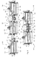
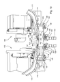
- An embodiment of the invention described below is shown in the drawings, in which:
- Fig. 1
- is a front perspective view of a grass mowing machine with an elective down pressure system for cutting units according to a first embodiment of the invention.
- Fig. 2
- is a rear perspective view of two rows of reel-type cutting units with an elective down pressure system according to a first embodiment, with the cutting units in a raised position.
- Fig. 3
- is rear perspective view of two rows of reel-type cutting units with an elective down pressure system according to a first embodiment, with the cutting units in a lowered position and without downforce applied to the cutting units.
- Fig. 4
- is a rear perspective view of two rows of reel-type cutting units with an elective down pressure system according to a first embodiment, with the cutting units in a lowered position and having downforce applied to the cutting units.
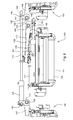
- Fig.5
- is a rear view of part of a first row of reel-type cutting units with an elective down pressure system according to a first embodiment, in which the cutting units are raised for transport or service.
- Fig. 6
- is a rear view of part of a first row of reel-type cutting units with an elective down pressure system according to a first embodiment, in which the cutting units are lowered for mowing in the no downforce position.
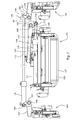
- Fig. 7
- is a rear view of part of a first row of reel-type cutting units with an elective down pressure system according to a first embodiment, in which the cutting units are lowered for mowing in the downforce position.
- Fig. 8
- is a rear view of part of a second row of reel-type cutting units with an elective down pressure system according to a first embodiment, in which the cutting units are raised for transport or service.
- Fig. 9
- is a rear view of part of a second row of reel-type cutting units with an elective down pressure system according to a first embodiment, in which the cutting units are lowered for mowing in the no downforce position.
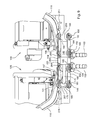
- Fig. 10
- is a rear view of part of a second row of reel-type cutting units with an elective down pressure system according to a first embodiment, in which the cutting units are lowered for mowing in the downforce position.
- In one embodiment shown in
Figs. 1-4 ,grass mowing machine 100 may be a fairway mower includingtraction vehicle 101 carrying a first row of three reel-type cutting units 102-04 and a second row of two reel-type cutting units 105-06. Alternatively, the grass mowing machine may be a greens mower or any other type of mower having two or more cutting units. The cutting units may be rotary or reel-type cutting units. - In the embodiment of
Figs. 1-4 , each cutting unit 102-06 may be connected to the outer end of a lift arm 107-11. A first or inner end of each lift arm may be pivotably attached to the frame or body of the traction vehicle, and the second or outer end may be pivotably attached to a cutting unit with a knuckle joint 119-23 to cross bar 113-17 or yolk supporting the cutting unit. The knuckle joint may allow the cutting unit to pivot on a generally vertical axis and/or horizontal axis while it is raised for transport or service, or while it is on the ground surface for mowing. While a cutting unit is on the ground surface, it may be supported with a front roller 126-30 and a rear roller 132-36. - Each lift and lower mechanism may be connected to one or more lift arms 107-11 so as to urge the lift arms in a first direction to raise one or more cutting units to a transport position, or in a second direction to lower one or more cutting units to the ground surface. In the embodiment of
Figs. 1-4 , the lift and lower mechanisms are hydraulic cylinders 138-40 having extensible rods 172-74. The extensible rods can be retracted to urge lift arms 107-11 in a first direction to raise the cutting units to a transport position, or extended to urge the lift arms in a second direction to lower the cutting units to the ground surface. Each lift and lower mechanism may be connected to a single lift arm, or between two lift arms. Each lift arm may be connected to a rotatable shaft, and the lift and lower mechanism may be connected to a crank on the shaft. - Additionally, each lift and lower mechanism may be set to either a downforce position in which the mechanism continues to urge the lift arm in a second direction to apply downforce to the cutting units while the cutting units are on the ground surface, or to a no downforce position in which the lift and lower mechanism discontinues urging the lift arm in a second direction to apply downforce to the cutting units once they are on the ground surface. Each lift and lower mechanism may include a lost motion coupling that may be set to a downforce or no downforce position. The lost motion coupling may be a slotted connection with a removable pin shown in
Figs. 5-7 depicting a first or front row of cutting units 102-04, or slotted plates shown inFigs. 8-10 depicting a second or back row of cutting units 105-06. - Although hydraulic cylinders 138-40 are preferred lift and lower mechanisms, other mechanical, hydraulic, pneumatic or electrical devices may perform these functions, and also may provide down pressure to a cutting unit once it has been lowered to the ground surface. An operator may elect downforce or no downforce for a cutting unit by setting the lift and lower mechanism at the desired position.
- In the embodiment of
Figs. 5-7 , the lift and lower mechanism for cuttingunits hydraulic cylinder 138 which retractsextensible rod 172 to raise cuttingunits Pivot pin 145 may connecthydraulic cylinder 138 to crank 151 onshaft 159.Pivot pin 146 may connect lostmotion coupling 142 on the end ofrod 172 to crank 152 onshaft 161. Crank 151 andlift arm 107 are both attached toshaft 159, and crank 152 andlift arm 109 are both attached toshaft 161. Retractingrod 172 causes cranks 151 and 152 to turn, turningshafts arms units - As shown in
Fig. 6 ,hydraulic cylinder 138 may extendrod 172 to lower cuttingunits pin 176 fromhole 166 in lostmotion coupling 142. In the no downforce position,pivot pin 146 is not captured at the outer end of the lost motion coupling. As a result, once cuttingunits rod 172 andhydraulic cylinder 138 do not continue pushing outwardly against pivot pins 145-46. While cuttingunits arms units motion coupling 142 allowsrod 172 to continue extending fromhydraulic cylinder 138 without continuing to urge the cutting units down. - As shown in
Fig. 7 , an operator may elect application of downforce to cuttingunits pin 176 intohole 166 in lostmotion coupling 142. In the downforce position,pivot pin 146 is captured at the outer end of the lost motion coupling. As a result, once cuttingunits rod 172 andhydraulic cylinder 138 continue to push outwardly against pivot pins 145-46. While cuttingunits cranks arms units - Also shown in
Figs. 5-7 , the lift and lower mechanism for cuttingunit 103 may behydraulic cylinder 139 that may retractrod 173 to raise cuttingunit 103 to a transport or service position.Pivot pin 147 may connecthydraulic cylinder 139 to the mower frame.Pivot pin 148 may connect lostmotion coupling 143 on the end ofrod 173 to crank 153 onshaft 160. Crank 153 andlift arm 108 are both attached toshaft 160. Retractingrod 173 causes crank 153 to turn,rotating shaft 160 in a direction to pivotlift arm 108 to raise cuttingunit 103. - As shown in
Fig. 6 ,hydraulic cylinder 139 may extendrod 173 to lower cuttingunit 103 without applying downforce. The operator may elect no downforce by removingpin 177 fromhole 167 in lostmotion coupling 143. In the no downforce position,pivot pin 148 is not captured at the outer end of the lost motion coupling. As a result, once cuttingunit 103 is lowered to the ground surface, in the no downforce position,rod 173 does not push againstpivot pin 148. While cuttingunit 103 remains in the lowered position, the lift and lower mechanism does not urge crank 153 andlift arm 108 to pivot in a direction to apply downforce to the cutting unit. While cuttingunit 103 is on the ground surface, lostmotion coupling 143 allowsrod 173 to continue extending fromhydraulic cylinder 139 without continuing to urge the cutting unit down. - As shown in
Fig. 7 , the operator may elect to apply downforce to cuttingunit 103 by insertingpin 177 intohole 167 in lostmotion coupling 143. In the downforce position,pivot pin 148 is captured at the outer end of the lost motion coupling. As a result, once cuttingunit 103 is lowered to the ground surface, in the downforce position,rod 173 pushes againstpivot pin 148, causing crank 153 andlift arm 108 to pivot in a direction to apply downforce to cuttingunit 103. - As shown in
Figs. 8-10 , the lift and lower mechanism for cutting units 105-06 may behydraulic cylinder 140 that retractsrod 174 to raise cutting units 105-06 to a transport or service position. In one embodiment,sleeve 175 may be connected transversely torod 174.Pivot pin 149 may be inserted throughsleeve 175, so that the pivot pin can slide alongslots plates Cranks lift arm 110 are attached toshaft 162, and cranks 155, 205 andlift arm 111 are attached toshaft 163. Ifrod 174 is retracted, this causespivot pin 164 to slide toward the inboard ends ofslots pivot pin 165 also slides toward the inboard ends ofslots - As shown in
Fig. 9 ,rod 174 may be extended to lower cutting units 105-06 without applying downforce. The operator may elect no downforce by inserting spacers 187-88 into lostmotion couplings motion couplings rod 174 is extended, this causespivot pin 164 to slide toward the outboard ends ofslots pivot pin 165 also slides toward the outboard ends ofslots rod 174 to extend fully fromhydraulic cylinder 140 without continuing to urge cranks 154-55, shafts 162-63, or lift arms 110-11 to pivot. - As shown in
Fig. 10 , downforce may be electively applied to cutting units 105-06 by inserting spacers 187-88 into slots 181-82, and spacers 207-08 in slots 191-92 in an alignment that urges lift arms 110-11 to pivot downward while the cutting units are on the ground surface. In the downforce position, spacers 187-88 block pivot pins 149-50 from reaching the outer ends of the slots. As a result, ifrod 174 is extended fromhydraulic cylinder 140, it pushes pivot pins 149-50 outwardly. Lost motion couplings 195-98 transmit the outward motion of pivot pins 149-50 to urge cranks 154-55 and lift arms 110-11 to pivot in a direction to apply downforce to cutting units 105-06. - Having described the preferred embodiment, it will become apparent that various modifications can be made without departing from the scope of the invention as defined in the accompanying claims.
Claims (10)
- Down pressure system for cutting units of a grass mowing machine (100), comprising at least a first lift arm (107 - 111) supporting a first cutting unit (102 - 106); a lift and lower mechanism connected to the first lift arm (107 - 111) to urge the first lift arm (107 - 111) in a first direction to raise the first cutting unit (102 - 106) to a transport position, or in a second direction to lower the first cutting unit (102 - 106) to the ground surface; characterized in that the lift and lower mechanism having a lost motion coupling (142, 143, 195, 197, 198) that may be set to either a downforce position in which the mechanism continues to urge the first lift arm (107 - 111) in a second direction to apply downforce to the first cutting unit (102 - 106) while the first cutting unit (102 - 106) is on the ground surface, or may be set to a no downforce position in which the lift and lower mechanism discontinues urging the first lift arm (107 - 111) in a second direction to stop application of downforce to the first cutting unit (102 - 106) once the first cutting unit (102 - 106) is on the ground surface.
- The down pressure system according to claim 1, characterized in that the lost motion coupling (142, 143, 195, 197, 198) is a slotted connection with a removable pin (176, 177).
- The down pressure system according to claim 1 or 2, characterized in that the lift and lower mechanism is a hydraulic cylinder (138 - 140) with an extensible rod (172, 173, 174), the hydraulic cylinder (138 - 140) preferably urging the extensible rod toward a retracted position or an extended position.
- The down pressure system according to claim 3, characterized in that the rod (172, 173, 174) retracts to urge the first lift arm (107 - 111) in a first direction to raise the first cutting unit (102 - 106) to a transport position, and extends to urge the first lift arm (107 - 111) in a second direction to lower the first cutting unit (102 - 106) to the ground surface.
- The down pressure system according to one or several of the previous claims, characterized in that the first lift arm (107 - 111) is connected to a rotatable shaft (159 - 163) and the lift and lower mechanism is connected to a crank (151 - 155, 204, 205) on the shaft (159 - 163) or that the lift arm (107 - 111) has a first end attached to the cutting unit (102 - 106) and a second end attached to a shaft (159 - 163).
- The down pressure system according to one or several of the previous claims, characterized by a second lift arm (107-111) supporting a second cutting unit (102 - 106), the lift and lower mechanism connected between the first and second lift arms (107 - 111) and/or wherein the hydraulic cylinder (138 - 140) and rod (172, 173, 174) are connected between a first cutting unit and a second cutting unit (102 - 106).
- The down pressure system according to one or several of the claims 3 to 5, characterized in that the lost motion coupling 142, 143, 195, 197, 198) connecting the rod (172, 173, 174) to the cutting unit (102 - 106), the rod (172, 173, 174) moving toward the retracted position to raise the cutting unit (102 - 106) to a transport position, or toward the extended position to lower the cutting unit (102 - 106) to the ground surface;
- The down pressure system according to one or several of the previous claims, characterized by a plurality of cutting units (102 - 106), a plurality of lift and lower mechanisms or hydraulic cylinders (138 - 140) with extensible rods (172, 173, 174) respectively, and a plurality of lost motion couplings (142, 143, 195, 197, 198) connecting the rods (172, 173, 174) to the plurality of cutting units (102- 106).
- The down pressure system according to one or several of the previous claims, characterized by a removable pin (176, 177) in the lost motion coupling (142, 143, 195, 197, 198) to set the lost motion coupling (142, 143, 195, 197, 198) to either the downforce position or the no downforce position.
- Grass mowing machine (100), characterized by a down pressure system according to one or several of the previous claims.
Applications Claiming Priority (1)
| Application Number | Priority Date | Filing Date | Title |
|---|---|---|---|
| US11/633,830 US7971417B2 (en) | 2006-12-05 | 2006-12-05 | Elective down pressure system for cutting units of grass mowing machine |
Publications (2)
| Publication Number | Publication Date |
|---|---|
| EP1929855A1 true EP1929855A1 (en) | 2008-06-11 |
| EP1929855B1 EP1929855B1 (en) | 2012-05-02 |
Family
ID=39156283
Family Applications (1)
| Application Number | Title | Priority Date | Filing Date |
|---|---|---|---|
| EP07121671A Not-in-force EP1929855B1 (en) | 2006-12-05 | 2007-11-27 | Elective down pressure system |
Country Status (2)
| Country | Link |
|---|---|
| US (1) | US7971417B2 (en) |
| EP (1) | EP1929855B1 (en) |
Cited By (3)
| Publication number | Priority date | Publication date | Assignee | Title |
|---|---|---|---|---|
| EP2050329A1 (en) * | 2007-10-17 | 2009-04-22 | Deere & Company | Grass Mowing Machine |
| EP2798936A1 (en) * | 2013-05-03 | 2014-11-05 | Jacky Van de Sluis | Gang mower with reel mower cutting units |
| US11395459B2 (en) | 2013-05-03 | 2022-07-26 | Jacky Van De Sluis | Gang mower with reel mower cutting units carried by two V-shaped beams foldable on a trailer frame |
Families Citing this family (14)
| Publication number | Priority date | Publication date | Assignee | Title |
|---|---|---|---|---|
| US7971415B2 (en) * | 2008-05-28 | 2011-07-05 | Deere & Company | Grass mowing machine having adjustable width toolbar for mounting cutting units |
| US8109069B2 (en) * | 2009-04-30 | 2012-02-07 | The Toro Company | Proportional counterbalance system for mower cutting units |
| US8104253B2 (en) * | 2010-03-31 | 2012-01-31 | The Toro Company | Gang reel mower with differing front and rear reel cutting unit setup for improving aftercut appearance |
| US8769916B2 (en) * | 2011-05-09 | 2014-07-08 | Marloo Equipment, Llc | Farm implement for harvesting and mowing that is relesably couplable to and powered by a tractor |
| US8522517B2 (en) * | 2011-12-23 | 2013-09-03 | The Toro Company | Reel gang mower having different width front and rear cutting units |
| US8794344B2 (en) | 2012-09-06 | 2014-08-05 | Cnh Industrial America Llc | Down pressure control system for an agricultural implement |
| US9918430B2 (en) | 2014-02-03 | 2018-03-20 | Cnh Industrial Canada, Ltd. | Foldable triple front disk mower for self-propelled windrowers |
| JP5940623B2 (en) * | 2014-10-21 | 2016-06-29 | 株式会社Ihiシバウラ | Lawn mower |
| US10136579B2 (en) * | 2017-01-20 | 2018-11-27 | David D. Button | Mower for attachment to an agricultural vehicle |
| US10433483B2 (en) * | 2017-08-21 | 2019-10-08 | Cnh Industrial America Llc | Agricultural header with one or more movable wing sections |
| US12290023B2 (en) * | 2021-01-20 | 2025-05-06 | Venture Products, Inc. | Method and apparatus for mounting a flail mower |
| US12256667B2 (en) * | 2021-01-20 | 2025-03-25 | Venture Products, Inc. | Method and apparatus for mounting a flail mower |
| US12250901B2 (en) * | 2021-01-20 | 2025-03-18 | Venture Products, Inc. | Method and apparatus for mounting a flail mower |
| US12178154B2 (en) | 2021-01-20 | 2024-12-31 | Venture Products, Inc. | Method and apparatus for mounting a flail mower |
Citations (5)
| Publication number | Priority date | Publication date | Assignee | Title |
|---|---|---|---|---|
| GB1241751A (en) * | 1967-09-18 | 1971-08-04 | Ransomes Sims & Jefferies Ltd | Improvements in or relating to mowing machines |
| US3808778A (en) * | 1973-01-08 | 1974-05-07 | Jacobsen Mfg Co | Lawn mowers articularly supported on a tractor |
| US5042236A (en) | 1990-02-08 | 1991-08-27 | The Toro Company | Cutting reel suspension with adjustable spring downloading |
| US5297378A (en) | 1992-05-13 | 1994-03-29 | Deere & Company | Suspension mechanism for reel mowers |
| EP1685758A1 (en) * | 2005-01-28 | 2006-08-02 | Deere & Company | Coupling mechanism and mowing machine |
Family Cites Families (5)
| Publication number | Priority date | Publication date | Assignee | Title |
|---|---|---|---|---|
| US4266617A (en) * | 1979-02-23 | 1981-05-12 | Excel Industries, Inc. | Tractor with full-floating tool bar |
| US4723403A (en) * | 1986-09-24 | 1988-02-09 | New Holland Inc. | Latching mechanism for unitized raking implements |
| US4769976A (en) | 1987-02-11 | 1988-09-13 | The Toro Company | Method and apparatus for supporting a reel unit |
| US4864805A (en) | 1987-09-04 | 1989-09-12 | The Toro Company | System for supporting a working unit |
| US6412258B1 (en) * | 2000-08-31 | 2002-07-02 | Textron Inc. | Tractor-supported lawnmower having mowers movable up and down |
-
2006
- 2006-12-05 US US11/633,830 patent/US7971417B2/en active Active
-
2007
- 2007-11-27 EP EP07121671A patent/EP1929855B1/en not_active Not-in-force
Patent Citations (5)
| Publication number | Priority date | Publication date | Assignee | Title |
|---|---|---|---|---|
| GB1241751A (en) * | 1967-09-18 | 1971-08-04 | Ransomes Sims & Jefferies Ltd | Improvements in or relating to mowing machines |
| US3808778A (en) * | 1973-01-08 | 1974-05-07 | Jacobsen Mfg Co | Lawn mowers articularly supported on a tractor |
| US5042236A (en) | 1990-02-08 | 1991-08-27 | The Toro Company | Cutting reel suspension with adjustable spring downloading |
| US5297378A (en) | 1992-05-13 | 1994-03-29 | Deere & Company | Suspension mechanism for reel mowers |
| EP1685758A1 (en) * | 2005-01-28 | 2006-08-02 | Deere & Company | Coupling mechanism and mowing machine |
Cited By (9)
| Publication number | Priority date | Publication date | Assignee | Title |
|---|---|---|---|---|
| EP2050329A1 (en) * | 2007-10-17 | 2009-04-22 | Deere & Company | Grass Mowing Machine |
| US7637090B2 (en) | 2007-10-17 | 2009-12-29 | Deere & Company | Roller configuration having reduced overlap for a grass mowing machine |
| EP2798936A1 (en) * | 2013-05-03 | 2014-11-05 | Jacky Van de Sluis | Gang mower with reel mower cutting units |
| WO2014177692A1 (en) * | 2013-05-03 | 2014-11-06 | Van De Sluis Jacky | Gang mower with reel mower cutting units |
| EP3045029A1 (en) * | 2013-05-03 | 2016-07-20 | Jacky Van de Sluis | Gang mower with reel mower cutting units |
| AU2014261345B2 (en) * | 2013-05-03 | 2018-03-01 | Conny Van de Sluis | Gang mower with reel mower cutting units |
| US10130026B2 (en) | 2013-05-03 | 2018-11-20 | Jacky Van De Sluis | Gang mower with reel mower cutting units |
| AU2018200765B2 (en) * | 2013-05-03 | 2019-12-05 | Conny Van de Sluis | Gang mower with reel mower cutting units |
| US11395459B2 (en) | 2013-05-03 | 2022-07-26 | Jacky Van De Sluis | Gang mower with reel mower cutting units carried by two V-shaped beams foldable on a trailer frame |
Also Published As
| Publication number | Publication date |
|---|---|
| US7971417B2 (en) | 2011-07-05 |
| EP1929855B1 (en) | 2012-05-02 |
| US20080127619A1 (en) | 2008-06-05 |
Similar Documents
| Publication | Publication Date | Title |
|---|---|---|
| EP1929855B1 (en) | Elective down pressure system | |
| CA1088759A (en) | Agricultural machine structure | |
| US4854112A (en) | Turf maintenance apparatus | |
| DE68918986T2 (en) | Tractor with the mower pulled. | |
| US6837033B2 (en) | Agricultural bi-mower with cantilever beam suspension | |
| US8209946B2 (en) | Trailing transport rotary mower | |
| CA1238511A (en) | Flexibility for wide swath agricultural implements | |
| CA2300547C (en) | Frame support for tillage implement | |
| US4330981A (en) | Towable ganged mower | |
| US6698171B2 (en) | Tractor-supported lawnmower having mowers movable up and down | |
| US5740870A (en) | Agricultural implement with stacking wings | |
| CA2277518C (en) | Windrower platform side-to-side float balance adjustment | |
| CA2406416A1 (en) | Crop harvesting machine with recoil action on impact with an obstacle | |
| EP1093707B1 (en) | Agricultural automobile vehicle | |
| KR102060841B1 (en) | Crawler travel device | |
| CA2170078C (en) | Mower-conditioner platform suspension including single upper arm and hydraulic cylinder for platform lift | |
| DE2753069A1 (en) | HARVEST MACHINE | |
| EP1155609A1 (en) | Swathing device | |
| EP1300065B1 (en) | Mower with safety device | |
| DE69117953T2 (en) | HAY COMPUTING AND TURNING MACHINE | |
| EP1616474B1 (en) | A towed mower comprising a running frame and two mowing aggregates | |
| GB1583983A (en) | Harvesting machines | |
| EP1800532B1 (en) | Mowing machine | |
| EP1829444A1 (en) | Rotary swather | |
| DE4103011C2 (en) | Mower or hay machine |
Legal Events
| Date | Code | Title | Description |
|---|---|---|---|
| PUAI | Public reference made under article 153(3) epc to a published international application that has entered the european phase |
Free format text: ORIGINAL CODE: 0009012 |
|
| AK | Designated contracting states |
Kind code of ref document: A1 Designated state(s): AT BE BG CH CY CZ DE DK EE ES FI FR GB GR HU IE IS IT LI LT LU LV MC MT NL PL PT RO SE SI SK TR |
|
| AX | Request for extension of the european patent |
Extension state: AL BA HR MK RS |
|
| 17P | Request for examination filed |
Effective date: 20081211 |
|
| 17Q | First examination report despatched |
Effective date: 20090120 |
|
| AKX | Designation fees paid |
Designated state(s): DE GB |
|
| GRAP | Despatch of communication of intention to grant a patent |
Free format text: ORIGINAL CODE: EPIDOSNIGR1 |
|
| GRAS | Grant fee paid |
Free format text: ORIGINAL CODE: EPIDOSNIGR3 |
|
| GRAA | (expected) grant |
Free format text: ORIGINAL CODE: 0009210 |
|
| AK | Designated contracting states |
Kind code of ref document: B1 Designated state(s): DE GB |
|
| REG | Reference to a national code |
Ref country code: GB Ref legal event code: FG4D |
|
| REG | Reference to a national code |
Ref country code: DE Ref legal event code: R096 Ref document number: 602007022382 Country of ref document: DE Effective date: 20120628 |
|
| PLBE | No opposition filed within time limit |
Free format text: ORIGINAL CODE: 0009261 |
|
| STAA | Information on the status of an ep patent application or granted ep patent |
Free format text: STATUS: NO OPPOSITION FILED WITHIN TIME LIMIT |
|
| 26N | No opposition filed |
Effective date: 20130205 |
|
| REG | Reference to a national code |
Ref country code: DE Ref legal event code: R097 Ref document number: 602007022382 Country of ref document: DE Effective date: 20130205 |
|
| PGFP | Annual fee paid to national office [announced via postgrant information from national office to epo] |
Ref country code: DE Payment date: 20191021 Year of fee payment: 13 |
|
| REG | Reference to a national code |
Ref country code: DE Ref legal event code: R119 Ref document number: 602007022382 Country of ref document: DE |
|
| PG25 | Lapsed in a contracting state [announced via postgrant information from national office to epo] |
Ref country code: DE Free format text: LAPSE BECAUSE OF NON-PAYMENT OF DUE FEES Effective date: 20210601 |
|
| PGFP | Annual fee paid to national office [announced via postgrant information from national office to epo] |
Ref country code: GB Payment date: 20231127 Year of fee payment: 17 |
|
| GBPC | Gb: european patent ceased through non-payment of renewal fee |
Effective date: 20241127 |
|
| PG25 | Lapsed in a contracting state [announced via postgrant information from national office to epo] |
Ref country code: GB Free format text: LAPSE BECAUSE OF NON-PAYMENT OF DUE FEES Effective date: 20241127 |