EP1929588B1 - Electrical connector assembly with connection assist - Google Patents
Electrical connector assembly with connection assist Download PDFInfo
- Publication number
- EP1929588B1 EP1929588B1 EP06786668.1A EP06786668A EP1929588B1 EP 1929588 B1 EP1929588 B1 EP 1929588B1 EP 06786668 A EP06786668 A EP 06786668A EP 1929588 B1 EP1929588 B1 EP 1929588B1
- Authority
- EP
- European Patent Office
- Prior art keywords
- electrical connector
- housing
- slot
- mating
- slide
- Prior art date
- Legal status (The legal status is an assumption and is not a legal conclusion. Google has not performed a legal analysis and makes no representation as to the accuracy of the status listed.)
- Active
Links
- 230000013011 mating Effects 0.000 claims description 27
- 230000002787 reinforcement Effects 0.000 description 3
- 238000012986 modification Methods 0.000 description 2
- 230000004048 modification Effects 0.000 description 2
- 239000004020 conductor Substances 0.000 description 1
- 238000011161 development Methods 0.000 description 1
- 230000018109 developmental process Effects 0.000 description 1
- 239000000463 material Substances 0.000 description 1
- 238000007789 sealing Methods 0.000 description 1
Images


Classifications
-
- H—ELECTRICITY
- H01—ELECTRIC ELEMENTS
- H01R—ELECTRICALLY-CONDUCTIVE CONNECTIONS; STRUCTURAL ASSOCIATIONS OF A PLURALITY OF MUTUALLY-INSULATED ELECTRICAL CONNECTING ELEMENTS; COUPLING DEVICES; CURRENT COLLECTORS
- H01R13/00—Details of coupling devices of the kinds covered by groups H01R12/70 or H01R24/00 - H01R33/00
- H01R13/62—Means for facilitating engagement or disengagement of coupling parts or for holding them in engagement
- H01R13/629—Additional means for facilitating engagement or disengagement of coupling parts, e.g. aligning or guiding means, levers, gas pressure electrical locking indicators, manufacturing tolerances
- H01R13/62933—Comprising exclusively pivoting lever
- H01R13/62944—Pivoting lever comprising gear teeth
-
- H—ELECTRICITY
- H01—ELECTRIC ELEMENTS
- H01R—ELECTRICALLY-CONDUCTIVE CONNECTIONS; STRUCTURAL ASSOCIATIONS OF A PLURALITY OF MUTUALLY-INSULATED ELECTRICAL CONNECTING ELEMENTS; COUPLING DEVICES; CURRENT COLLECTORS
- H01R13/00—Details of coupling devices of the kinds covered by groups H01R12/70 or H01R24/00 - H01R33/00
- H01R13/62—Means for facilitating engagement or disengagement of coupling parts or for holding them in engagement
- H01R13/629—Additional means for facilitating engagement or disengagement of coupling parts, e.g. aligning or guiding means, levers, gas pressure electrical locking indicators, manufacturing tolerances
- H01R13/62933—Comprising exclusively pivoting lever
- H01R13/62938—Pivoting lever comprising own camming means
-
- H—ELECTRICITY
- H01—ELECTRIC ELEMENTS
- H01R—ELECTRICALLY-CONDUCTIVE CONNECTIONS; STRUCTURAL ASSOCIATIONS OF A PLURALITY OF MUTUALLY-INSULATED ELECTRICAL CONNECTING ELEMENTS; COUPLING DEVICES; CURRENT COLLECTORS
- H01R13/00—Details of coupling devices of the kinds covered by groups H01R12/70 or H01R24/00 - H01R33/00
- H01R13/62—Means for facilitating engagement or disengagement of coupling parts or for holding them in engagement
- H01R13/629—Additional means for facilitating engagement or disengagement of coupling parts, e.g. aligning or guiding means, levers, gas pressure electrical locking indicators, manufacturing tolerances
- H01R13/62933—Comprising exclusively pivoting lever
- H01R13/62966—Comprising two pivoting levers
- H01R13/62972—Wherein the pivoting levers are two lever plates
Definitions
- the invention relates to an electrical connector and, more particularly, to a system for mating two electrical connectors with each other.
- U.S. Patent No. 6,120,308 discloses an electrical connector assembly which can be rotatably connected and disconnected.
- EP 0 674 362 discloses an electrical connector assembly with a note assist system having a slide.
- an electrical connector including electrical contacts; a housing having the electrical contacts connected thereto; and a mate assist system for assisting in mating the electrical connector to a mating electrical connector.
- the mate assist system includes a cam member movably mounted to the housing having a slot for receiving a cam portion of the mating electrical connector and a rack section with teeth engaging a user actuatable member movably mounted to the housing.
- an electrical connector comprising electrical contacts; a housing having the electrical contacts connected thereto; and a mate assist system for assisting in mating the electrical connector to a mating electrical connector.
- the mate assist system comprises at least two lever arms pivotably connected to the housing. Each lever arm comprises a slot for receiving at least one cam portion of the mating electrical connector. The lever arms at least partially cross each other.
- an electrical connector comprising a housing; a plurality of electrical contacts connected to the housing; at least one shorting bar connected to the housing and movably connected to the electrical contacts; a slide slidably mounted to the housing, wherein the slide comprises a first rack section with teeth; and a cam member pivotably mounted to the housing having a slot for receiving a cam portion of a mating electrical connector.
- the cam member comprises a second rack section with teeth engaging the teeth of the first rack section.
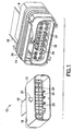
- FIG. 1 there is shown an exploded perspective view of an electrical connector assembly 10 incorporating features of the invention.
- an electrical connector assembly 10 incorporating features of the invention.
- the assembly 10 generally comprises a first electrical connector 12, a second electrical connector 14 and electrical conductors 16, such as wires, connected to the electrical connectors 12, 14.
- the two electrical connectors 12, 14 are adapted to removably mate with each other to electrically connected their respective wires 16 to each other.
- the first electrical connector 12 generally comprises a housing 18, electrical contacts 20 and a mat wire seal 27 (see Figs. 2A and 2B ).
- the mat wire seal 27 forms seals and strain relief for the wires 16 entering the rear of the connector 12.
- the seal 27 is located between the rear end of the outer housing member 24 and the rear end of the inner housing member 22.
- the seal has holes to allow wires to pass through the seal and which makes a sealing contact with the wires.
- the housing 18 generally comprises an inner housing member 22, an outer housing member 24, and a combined terminal position assurance (TPA) and primary lock reinforcement (PLR) (TPA/PLR) member 26.
- the electrical contacts 20 are mounted in contact receiving channels 28 inside the inner housing member 22.
- the contacts 20 are crimped or otherwise connected to the wires 16 of the first connector 12.
- the inner housing member 22 is stationarily mounted inside the outer housing member 24.
- the TPA/PLR member 26 is movably mounted on the front end of the inner housing member 22.
- the inner housing 22 has locking latches at the receiving channels 28 for latching the electrical contacts 20 in the receiving channels 28.
- the TPA/PLR member 26 is pushed rearward on the inner housing 22 to reinforce the electrical contact locking latches.
- any suitable type of inner housing could be provided and any suitable type of terminal position assurance and primary lock reinforcement could be provided.
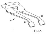
- the first connector 12 includes electrical shorting bar contacts 30 mounted on the inner housing member 22.
- the shorting bar contacts electrically connect pairs of the electrical connectors 20 to each other before the second connector 14 is mated with the first connector 12.
- the second connector 14 has projections 44 which are adapted to move the contact arms 31 of the shorting bar contacts 30 off of connection with the contacts 20.
- the shorting bars might not be provided.
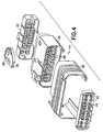
- the second electrical connector generally comprises a housing 32, electrical contacts 34 and a slide 36.
- the housing 32 generally comprises a main housing member 38, a rear end seal cover 40 and a front end combined terminal position assurance (TPA) and primary lock reinforcement (PLR) (TPA/PLA) member 42.
- the TPA/PLR member 42 is mounted to the front end of the main housing member 38, such as with a snap lock connection for example.
- the TPA/PLR member 42 includes forward projecting isolators 44 which are adapted to move the contact arms 31 of the shorting bar contacts 30 off of connection with the contacts 20 when the second electrical connector 14 is connected to the first electrical connector 12.
- a mat wire seal similar to the seal 27 shown in Figs. 2A and 2B is located between the rear end of the main housing member 38 and the rear end seal cover 40.
- a perimeter seal (not shown) is also provided on the second connector 14 to form a seal with the housing of the first connector 12.
- any suitable structure(s) could be provided for the housing component(s) of the second connector 14.
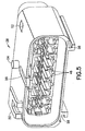
- the main housing member 38 comprises contact receiving areas 46.
- the electrical contacts 34 are mounted in the receiving areas 46.
- the main housing member 38 comprises latches for latching the contacts 34 in the receiving areas 46.
- the TPA/PLR member 42 when moved to a locked position on the main housing member 38, strengthens the latches to prevent inadvertent withdrawal of the contacts 34 from the main housing member 38.
- a top side of the main housing member 38 comprises a first deflectable latch 50, a second latch receptacle 52, a pivot pin 54 and a slot 56.
- the bottom side of the main housing member 38 comprises two slide slots 58.
- the rear end seal cover 40 is mounted to the rear end of the main housing member 38, such as with a snap lock connection for example.
- the rear seal cover 40 includes wire strain relief tubes 48.
- the wires 16 of the second connector 14 extend through the wire strain relief tubes 48 of the rear seal cover 40 and into the receiving areas 46.
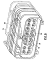
- the slide 36 comprises a top with a first latch 60, a second latch 62, and a rack of teeth 64 located on the interior facing side of the top.
- the bottom of the slide 36 has slide feet 66.
- the feet 66 are sized and shaped to be received in the slide slots 58 of the main housing member 38 and slide therealong.
- the slide 36 is sized and shaped to be mounted over and substantially surround the main housing member 38.
- the slide 36 can slide along the main housing member between a rear position and a forward position.
- the first latch 60 When the slide is moved to the forward position by a user, the first latch 60 is adapted to latch with the first deflectable latch 50 to retain the slide 36 at a forward position on the main housing member 38. Thus, the first latch 60 and the first deflectable latch 50 form a first latch system.
- the second latch 62 is adapted to engage the second latch receptacle 52 to retain the slide 36 at the retracted rear position on the main housing member 38 until positively moved by a user.
- the second latch 62 and the second latch receptacle 52 form a second latch system.
- the second connector 14 also comprises a combined pinion gear and cam member 68.
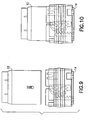
- Fig. 8 shows the slide 36 at its rear home position.
- Fig. 8 also shows the member 68 at its corresponding home position.
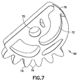
- the member 68 comprises a pivot hole 70, a pin slot 72, and a gear section 74 with teeth 76.
- the member 68 is rotatably mounted on the main housing member 38 with the pivot pin 54 located in the pivot hole 70.
- the teeth 76 are adapted to intermesh with the teeth 64 of the rack section on the slide 36.
- the pin slot 72 has a general curved shape in this embodiment.
- the pin slot 72 has an entrance 78 that is aligned with the slot 56 when the member 68 is at a home position on the main housing member 38.
- the slot 56 has a general straight shape in this embodiment.
- the slot 56 and pin slot 72 are adapted to receive the mounting pin 25 (see Figs. 1 and 2 ) of the first connector 12 when the first and second connectors are attached to each other.
- the mounting pin 25 is sized and shaped to slide along the slot 56.
- the member 68 is adapted to rotate to assist in moving the pin 25 along the length of the slot 56; functioning as a cam and mate assist. More specifically, and referring also to Figs. 9-12 , the user can grasp the slide 36 during connection of the two connectors 12, 14 to each other.
- the latching by the second latch 62 and second latch receptacle 52 is overcome because the housing 24 moves the second latch 62.
- the slide 36 can then begin to slide forward on the main housing member 38.
- the slide 36 is freed to move when the slide latch 62 is deflected free and disengaged from the latch window 52 by the leading edge of the opposing connector 12 outer housing 24.
- the latch system 50, 60 is disengaged by the user and the slide 36 is moved to its rearward position.
- the intermeshing teeth 64, 76 cause the member 68 to rotate while the slide 36 is moved to eject the pin 25, at least partially, from the slot 56.
- the invention can also be used to assist in disconnecting the two connectors 12, 14.
- the electrical connector 80 comprises a housing 82, a mate-assist sleeve or slide 84 and two mate-assist lever arms 86.
- the housing 82 comprises a top side with two pin receiving slots 88 and two pivot posts 90.
- the two lever arms 86 are pivotably mounted on the pivot posts 90 at holes 92.
- the lever arms 86 cross each other.
- Slide 84 is mounted over the housing 82.
- the slide 84 comprises inwardly extending posts 94.
- the posts are located in the slots 96 of the lever arms 86.
- the lever arms 86 also comprise open ended slots 98.
- the open ended slots 98 are aligned with the slots 88 to receive and capture pins 100 of a mating connector as seen in Fig. 13 .
- the slide 84 causes the lever arms 86 to move on the housing, similar to a scissors action. This positions the lever arms 86 to receive the pins 100 when the slide is in a rearward position, and cam the pins 100 into the slots 88 of the housing 82 as the slide is moved forward on the housing.
- This type of embodiment may be particularly advantageous for connectors having longer widths, and/or helping to use a balanced, multi-point applied system to smaller size connectors.
- the connector 102 comprises a housing 104, a slide 106 and two lever arms 108.
- the housing 104 comprises a mating connector pin receiving slot 110 and two pivot posts 112.
- the lever arms 108 each comprise pivot holes 114 and two open ended slots 116, 118.
- the lever arms 108 are pivotably mounted on the pivot posts 112 at the holes 114 and at least partially cross each other.
- the slide 106 has two inwardly facing posts 120.
- the posts 120 are located in the slots 118.
- the slots 116 are aligned with the slot 110.
- the mounting pin for the mating electrical connector (not shown) can be received in the slot 110 with the slide 106 moving the lever arms 108 to cam the mounting pin of the mating electrical connector into the slot 110.
- Fig. 25 shown an alternate shape of a lever arm 121 with a pivot hole 122, a post 124 and a cam slot 126.
- any suitable shape could be provided.
- a housing/TPA/seal cover design strategy on the male housing could be used as opposed to the outer-housing/inner-housing/TPA strategy that is shown.
- a connector without shorting bars could be provided.
- the first electrical connector 130 is identical to the first electrical connector 12 except that the housing of the first electrical connector 130 comprises keying features 132 extending from its bottom side.
- the second electrical connector 134 is identical to the second electrical connector 14 except for the following: 1. a guide 136 at the entrance to the slot 56, a guide projection 138 on the top side of the housing 32', the slide 36' is closed at its bottom side at area 140, the slide 36' has closed side rectangular guide slots 142 at its bottom side, and the housing 32' has generally rectangular projections 144 on its bottom side with L shaped slots 146 extending into the top side.
- the slots 146 form a receiving area for receiving the keying features 132 of the first connector 130.
- any suitable keying features could be provided.
Description
- The invention relates to an electrical connector and, more particularly, to a system for mating two electrical connectors with each other.
-
U.S. Patent No. 6,120,308 discloses an electrical connector assembly which can be rotatably connected and disconnected.EP 0 674 362 discloses an electrical connector assembly with a note assist system having a slide. - In accordance with one aspect of the invention, an electrical connector is provided including electrical contacts; a housing having the electrical contacts connected thereto; and a mate assist system for assisting in mating the electrical connector to a mating electrical connector. The mate assist system includes a cam member movably mounted to the housing having a slot for receiving a cam portion of the mating electrical connector and a rack section with teeth engaging a user actuatable member movably mounted to the housing.
- In accordance with another aspect of the invention, an electrical connector is provided comprising electrical contacts; a housing having the electrical contacts connected thereto; and a mate assist system for assisting in mating the electrical connector to a mating electrical connector. The mate assist system comprises at least two lever arms pivotably connected to the housing. Each lever arm comprises a slot for receiving at least one cam portion of the mating electrical connector. The lever arms at least partially cross each other.
- In accordance with another aspect of the invention, an electrical connector is provided comprising a housing; a plurality of electrical contacts connected to the housing; at least one shorting bar connected to the housing and movably connected to the electrical contacts; a slide slidably mounted to the housing, wherein the slide comprises a first rack section with teeth; and a cam member pivotably mounted to the housing having a slot for receiving a cam portion of a mating electrical connector. The cam member comprises a second rack section with teeth engaging the teeth of the first rack section.
- The foregoing aspects and other features of the invention are explained in the following description, taken in connection with the accompanying drawings, wherein:
-
Fig. 1 is an exploded perspective view of two electrical connectors used to form an electrical connector assembly; -
Fig. 2 is an exploded perspective view of some components of a first one of the electrical connectors shown inFig. 1 ; -
Fig. 2A is a perspective view of a mat wire seal used in the electrical connector shown inFig. 2 ; -
Fig. 2B is a front elevational view of the mat wire seal shown inFig. 2A ; -
Fig. 3 is a perspective view of the shoring bar used in the connector shown inFig. 2 ; -
Fig. 4 is an exploded perspective view of some components of the second electrical connector shown inFig. 1 ; -
Fig. 5 is a perspective view of a main housing member of the connector shown inFig. 4 ; -
Fig. 6 is a perspective view of the slide of the connector shown inFig. 4 ; -
Fig. 7 is a perspective view of the combined pinion gear and cam member shown inFig. 4 ; -
Fig. 8 is a perspective view of the connector shown inFig. 4 with the slide in a rearward position; -
Fig. 9 is a top plan view of the two connectors shown inFig. 1 about to be connected to each other; -
Fig. 10 is a top plan view as inFig. 9 with the two connectors initially connected to each other; -
Fig. 11 is a top plan view as inFig. 10 with the two connectors further connected to each other; -
Fig. 12 is a top plan view as inFig. 11 with the two connectors connected to each other at a final connection position; -
Fig. 13 is a top plan view with a cut away of an alternate embodiment of the invention; -
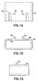
Fig. 14 is a top plan view of the housing of the connector shown inFig. 13 ; -
Fig. 15 is a front elevational view of the housing of the connector shown inFig. 13 ; -
Fig. 16 is a side elevational view of the housing of the connector shown inFig. 13 ; -
Fig. 17 is a top plan view of one of the lever arms of the connector shown inFig. 13 ; -
Fig. 18 is a side elevational view of the lever arm shown inFig. 17 ; -
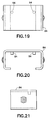
Fig. 19 is a top plan view of the slide of the connector shown inFig. 13 ; -
Fig. 20 is a front elevational view of the slide shown inFig. 19 ; -
Fig. 21 is a side elevational view of the slide shown inFig. 19 ; -
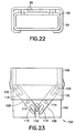
Fig. 22 is a front elevation view of the connector shown inFig. 13 ; -
Fig. 23 is a top plan view of an alternate embodiment of a connector comprising features of the invention; -
Fig. 24 is a top plan view of the housing of the connector shown inFig. 23 ; -
Fig. 25 is a top plan view of an alternate embodiment of a lever arm; -
Fig. 26 is perspective view of an alternate embodiment of the first electrical connector; -
Fig. 27 is another perspective view of the first electrical connector shown inFig. 26 ; -
Fig. 28 is a perspective view of another alternate embodiment of the second electrical connector for use with the first electrical connector shown inFigs. 26-27 ; and -
Fig. 29 is another perspective view of the second electrical connector shown inFig. 28 . - Referring to
Fig. 1 , there is shown an exploded perspective view of anelectrical connector assembly 10 incorporating features of the invention. Although the invention will be described with reference to the exemplary embodiments shown in the drawings, it should be understood that the invention can be embodied in many alternate forms of embodiments. In addition, any suitable size, shape or type of elements or materials could be used. - The
assembly 10 generally comprises a firstelectrical connector 12, a secondelectrical connector 14 andelectrical conductors 16, such as wires, connected to theelectrical connectors electrical connectors respective wires 16 to each other. The firstelectrical connector 12 generally comprises ahousing 18,electrical contacts 20 and a mat wire seal 27 (seeFigs. 2A and 2B ). Themat wire seal 27 forms seals and strain relief for thewires 16 entering the rear of theconnector 12. Theseal 27 is located between the rear end of theouter housing member 24 and the rear end of theinner housing member 22. The seal has holes to allow wires to pass through the seal and which makes a sealing contact with the wires. - Referring also to
Fig. 2 , thehousing 18 generally comprises aninner housing member 22, anouter housing member 24, and a combined terminal position assurance (TPA) and primary lock reinforcement (PLR) (TPA/PLR)member 26. Theelectrical contacts 20 are mounted incontact receiving channels 28 inside theinner housing member 22. Thecontacts 20 are crimped or otherwise connected to thewires 16 of thefirst connector 12. Theinner housing member 22 is stationarily mounted inside theouter housing member 24. The TPA/PLR member 26 is movably mounted on the front end of theinner housing member 22. Theinner housing 22 has locking latches at the receivingchannels 28 for latching theelectrical contacts 20 in the receivingchannels 28. After theelectrical contacts 20 are inserted into the receivingchannels 28 of theinner connector housing 22, the TPA/PLR member 26 is pushed rearward on theinner housing 22 to reinforce the electrical contact locking latches. However, in alternate embodiments any suitable type of inner housing could be provided and any suitable type of terminal position assurance and primary lock reinforcement could be provided. - Referring also to
Fig. 3 , thefirst connector 12 includes electrical shortingbar contacts 30 mounted on theinner housing member 22. The shorting bar contacts electrically connect pairs of theelectrical connectors 20 to each other before thesecond connector 14 is mated with thefirst connector 12. However, during mating of thesecond connector 14 with thefirst connector 12, thesecond connector 14 hasprojections 44 which are adapted to move thecontact arms 31 of the shortingbar contacts 30 off of connection with thecontacts 20. In an alternate embodiment the shorting bars might not be provided. - As seen in
Fig. 1 , the second electrical connector generally comprises ahousing 32,electrical contacts 34 and aslide 36. Referring also toFig. 4 , thehousing 32 generally comprises amain housing member 38, a rearend seal cover 40 and a front end combined terminal position assurance (TPA) and primary lock reinforcement (PLR) (TPA/PLA)member 42. The TPA/PLR member 42 is mounted to the front end of themain housing member 38, such as with a snap lock connection for example. The TPA/PLR member 42 includes forward projectingisolators 44 which are adapted to move thecontact arms 31 of the shortingbar contacts 30 off of connection with thecontacts 20 when the secondelectrical connector 14 is connected to the firstelectrical connector 12. A mat wire seal (not shown) similar to theseal 27 shown inFigs. 2A and 2B is located between the rear end of themain housing member 38 and the rearend seal cover 40. A perimeter seal (not shown) is also provided on thesecond connector 14 to form a seal with the housing of thefirst connector 12. However, in alternate embodiments, any suitable structure(s) could be provided for the housing component(s) of thesecond connector 14. - Referring also to
Fig. 5 , themain housing member 38 comprisescontact receiving areas 46. Theelectrical contacts 34 are mounted in the receivingareas 46. Themain housing member 38 comprises latches for latching thecontacts 34 in the receivingareas 46. The TPA/PLR member 42, when moved to a locked position on themain housing member 38, strengthens the latches to prevent inadvertent withdrawal of thecontacts 34 from themain housing member 38. A top side of themain housing member 38 comprises a firstdeflectable latch 50, asecond latch receptacle 52, apivot pin 54 and aslot 56. The bottom side of themain housing member 38 comprises twoslide slots 58. - The rear
end seal cover 40 is mounted to the rear end of themain housing member 38, such as with a snap lock connection for example. Therear seal cover 40 includes wirestrain relief tubes 48. Thewires 16 of thesecond connector 14 extend through the wirestrain relief tubes 48 of therear seal cover 40 and into the receivingareas 46. - Referring also to
Fig. 6 , theslide 36 comprises a top with afirst latch 60, asecond latch 62, and a rack ofteeth 64 located on the interior facing side of the top. The bottom of theslide 36 hasslide feet 66. Thefeet 66 are sized and shaped to be received in theslide slots 58 of themain housing member 38 and slide therealong. Theslide 36 is sized and shaped to be mounted over and substantially surround themain housing member 38. Theslide 36 can slide along the main housing member between a rear position and a forward position. - When the slide is moved to the forward position by a user, the
first latch 60 is adapted to latch with the firstdeflectable latch 50 to retain theslide 36 at a forward position on themain housing member 38. Thus, thefirst latch 60 and the firstdeflectable latch 50 form a first latch system. Thesecond latch 62 is adapted to engage thesecond latch receptacle 52 to retain theslide 36 at the retracted rear position on themain housing member 38 until positively moved by a user. Thus, thesecond latch 62 and thesecond latch receptacle 52 form a second latch system. - Referring also to
Figs. 7 and8 , thesecond connector 14 also comprises a combined pinion gear andcam member 68.Fig. 8 shows theslide 36 at its rear home position.Fig. 8 also shows themember 68 at its corresponding home position. Themember 68 comprises apivot hole 70, apin slot 72, and agear section 74 withteeth 76. Themember 68 is rotatably mounted on themain housing member 38 with thepivot pin 54 located in thepivot hole 70. Theteeth 76 are adapted to intermesh with theteeth 64 of the rack section on theslide 36. Thepin slot 72 has a general curved shape in this embodiment. Thepin slot 72 has anentrance 78 that is aligned with theslot 56 when themember 68 is at a home position on themain housing member 38. Theslot 56 has a general straight shape in this embodiment. - The
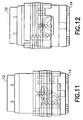
slot 56 andpin slot 72 are adapted to receive the mounting pin 25 (seeFigs. 1 and2 ) of thefirst connector 12 when the first and second connectors are attached to each other. The mountingpin 25 is sized and shaped to slide along theslot 56. Themember 68 is adapted to rotate to assist in moving thepin 25 along the length of theslot 56; functioning as a cam and mate assist. More specifically, and referring also toFigs. 9-12 , the user can grasp theslide 36 during connection of the twoconnectors first connector 12 is inserted into thesecond connector 14, the latching by thesecond latch 62 andsecond latch receptacle 52 is overcome because thehousing 24 moves thesecond latch 62. Theslide 36 can then begin to slide forward on themain housing member 38. Thus, theslide 36 is freed to move when theslide latch 62 is deflected free and disengaged from thelatch window 52 by the leading edge of the opposingconnector 12outer housing 24. - As the
slide 36 is moved forward on themain housing member 38, this causes the rack ofteeth 64 on theslide 36 to rotate themember 68 because of the intermeshed nature of theteeth Fig. 11 . As themember 68 rotates it cams thepin 25 to move deeper into the length of theslot 56. Thepin slot 72 cams against thepin 25 to help move the twoconnectors Fig. 12 . Thefirst latch 60 engages the firstdeflectable latch 50 to keep theslide 36 at its forward position on themain housing member 38 and, thus, keep the first andsecond connectors Fig. 12 . - To disconnect the two
connectors latch system slide 36 is moved to its rearward position. The intermeshingteeth member 68 to rotate while theslide 36 is moved to eject thepin 25, at least partially, from theslot 56. Thus, the invention can also be used to assist in disconnecting the twoconnectors - Referring now to
Figs. 13-22 another embodiment of the invention is shown. In this embodiment theelectrical connector 80 comprises ahousing 82, a mate-assist sleeve or slide 84 and two mate-assist lever arms 86. Thehousing 82 comprises a top side with twopin receiving slots 88 and two pivot posts 90. The twolever arms 86 are pivotably mounted on the pivot posts 90 at holes 92. As seen inFig. 13 , thelever arms 86 cross each other.Slide 84 is mounted over thehousing 82. Theslide 84 comprises inwardly extending posts 94. The posts are located in theslots 96 of thelever arms 86. Thelever arms 86 also comprise open endedslots 98. The open endedslots 98 are aligned with theslots 88 to receive and capturepins 100 of a mating connector as seen inFig. 13 . When theslide 84 is moved relative to thehousing 82, theslide 84 causes thelever arms 86 to move on the housing, similar to a scissors action. This positions thelever arms 86 to receive thepins 100 when the slide is in a rearward position, and cam thepins 100 into theslots 88 of thehousing 82 as the slide is moved forward on the housing. This type of embodiment may be particularly advantageous for connectors having longer widths, and/or helping to use a balanced, multi-point applied system to smaller size connectors. - Referring now to
Figs. 23-24 another embodiment is shown. In this embodiment theconnector 102 comprises ahousing 104, aslide 106 and twolever arms 108. Thehousing 104 comprises a mating connectorpin receiving slot 110 and two pivot posts 112. Thelever arms 108 each comprisepivot holes 114 and two open endedslots lever arms 108 are pivotably mounted on the pivot posts 112 at theholes 114 and at least partially cross each other. Theslide 106 has two inwardly facing posts 120. Theposts 120 are located in theslots 118. Theslots 116 are aligned with theslot 110. The mounting pin for the mating electrical connector (not shown) can be received in theslot 110 with theslide 106 moving thelever arms 108 to cam the mounting pin of the mating electrical connector into theslot 110. -
Fig. 25 shown an alternate shape of alever arm 121 with apivot hole 122, apost 124 and acam slot 126. However, any suitable shape could be provided. - In an alternate embodiment a housing/TPA/seal cover design strategy on the male housing could be used as opposed to the outer-housing/inner-housing/TPA strategy that is shown. In another embodiment a connector without shorting bars could be provided.
- Referring also to
Figs. 26-29 an alternate embodiment of the electrical connector assembly is shown. In this embodiment the firstelectrical connector 130 is identical to the firstelectrical connector 12 except that the housing of the firstelectrical connector 130 comprises keyingfeatures 132 extending from its bottom side. The secondelectrical connector 134 is identical to the secondelectrical connector 14 except for the following: 1. aguide 136 at the entrance to theslot 56, aguide projection 138 on the top side of the housing 32', the slide 36' is closed at its bottom side atarea 140, the slide 36' has closed siderectangular guide slots 142 at its bottom side, and the housing 32' has generallyrectangular projections 144 on its bottom side with L shapedslots 146 extending into the top side. Theslots 146 form a receiving area for receiving the keying features 132 of thefirst connector 130. However, in alternate embodiments, any suitable keying features could be provided. - It should be understood that the foregoing description is only illustrative of the invention. Various alternatives and modifications can be devised by those skilled in the art without departing from the invention. Accordingly, the invention is intended to embrace all such alternatives, modifications and variances which fall within the scope of the appended claims.
Claims (19)
- An electrical connector comprising:electrical contacts (34);a housing (38) having the electrical contacts (34) connected thereto; anda mate assist system for assisting in mating the electrical connector (14) to a mating electrical connector (12),characterized in that the mate assist system comprises a cam member (68) movably mounted to the housing (38) comprising a pin slot (72) for receiving a mounting pin (25) of the mating electrical connector (12) and a gear section (74) with teeth (76) engaging an user actuatable member (36) longitudinally slidably mounted on the housing (38) so as to slide, along a mating direction, between a rear position and a forward position.
- An electrical connector as in claim 1, wherein the cam member (68) is pivotably connected to the housing (38).
- An electrical connector as in any of the preceding claims, wherein the pin slot (72) is curved.
- An electrical connector as in any of the preceding claims, wherein the housing (38) comprises a cam portion slot (56) at least partially aligned with the pin slot (72) of the cam member (68).
- An electrical connector as in claim 4, wherein the cam portion slot (56) is substantially straight and the pin slot (72) of the cam member (68) is curved.
- An electrical connector as in any of the preceding claims, wherein the gear section of the cam member (68) comprises teeth (76) aligned along a curved path.
- An electrical connector as in claim 6, wherein the user actuatable member (36) comprises teeth (64) movably intermeshed with teeth (76) of the gear section (74) of the cam member (68).
- An electrical connector as in any of the preceding claims, wherein the housing (38) and the user actuatable member (36) comprise a first latch system (50, 60) for retaining the user actuatable member (36) at a first location on the housing (38) and a second latch system (52, 62) for retaining the user actuatable member (36) at a second location on the housing (38).
- An electrical connector as in any of the preceding claims, wherein the housing (38) comprises forward projecting members (44) adapted to project into the mating electrical connector (12) and move at least one shorting bar (30) of the mating electrical connector (12).
- An electrical connector comprising:electrical contacts (34);a housing (82) having the electrical contacts (34) connected thereto; anda mate assist system for assisting in mating the electrical connector (14) to a mating electrical connector (12),characterized in that the mate assist system comprises at least two lever arms (86, 108, 121) pivotably mounted to the housing (82), wherein each lever arm (86, 108, 121) comprises a slot (98, 118, 126) for receiving at least one capture pin (100) of the mating electrical connector,
wherein the lever arms (86, 108, 121) at least partially cross each other,
and an user actuatable member (84, 106) longitudinally slidably mounted on the housing (82) so as to slide, along a mating direction, between a rear position and a forward position. - An electrical connector as in claim 10, wherein the slot (98, 118, 126) of the lever arms (86) is substantially straight.
- An electrical connector as in claim 10, wherein the slot (98, 118, 126) of the lever arms (121) is curved.
- An electrical connector as in claim 10, wherein the slot (98, 118, 126) is located at a first end of the lever arm (86, 108) and a second end of the lever arm (86, 108) comprises a second slot (96, 118).
- An electrical connector as in claim 14, wherein the user actuatable member (84, 106) comprises cam projections (94, 120) located in the second slots (96, 118) of the lever arms (86, 108).
- An electrical connector as in claim 14, wherein the cam projections (94, 120) are adapted to longitudinally slide in the second cam slots (96, 118).
- An electrical connector as in claim 10, wherein the housing (82) comprises a cam slot (88) at least partially aligned with the slots (98, 118, 126) of the lever arms (86, 108, 121).
- An electrical connector as in claim 10, wherein the housing (82) comprises at least two spaced cam slots (88) at least partially aligned with respective ones of the slots (98, 118, 126) of the lever arms (86, 108, 121).
- An electrical connector as in claim 10, wherein the at least two lever arms (86, 108, 121) are pivotably connected to the housing (82) at respective spaced locations.
- An electrical connector comprising:a housing (38) comprising forward projecting members (44) adapted to project into a mating electrical connector (12) and move at least one shorting bar (30) of the mating electrical connector (12);a plurality of electrical contacts (34) connected to the housing (38);a slide (36) slidably mounted to the housing (38), so as to slide along a mating direction wherein the slide (36) comprises a first rack section with teeth (64); anda cam member (68) pivotably mounted to the housing (38) having a slot (72) for receiving a cam portion of a mating electrical connector (12), and wherein the cam member (68) comprises a second gear section (74) with teeth (76) engaging the teeth (64) of the first rack section.
Applications Claiming Priority (3)
| Application Number | Priority Date | Filing Date | Title |
|---|---|---|---|
| US70423205P | 2005-07-28 | 2005-07-28 | |
| US11/445,975 US7241155B2 (en) | 2005-07-28 | 2006-06-01 | Electrical connector assembly with connection assist |
| PCT/US2006/026589 WO2007018878A2 (en) | 2005-07-28 | 2006-07-10 | Electrical connector assembly with connection assist |
Publications (3)
| Publication Number | Publication Date |
|---|---|
| EP1929588A2 EP1929588A2 (en) | 2008-06-11 |
| EP1929588A4 EP1929588A4 (en) | 2011-07-20 |
| EP1929588B1 true EP1929588B1 (en) | 2016-09-07 |
Family
ID=37694956
Family Applications (1)
| Application Number | Title | Priority Date | Filing Date |
|---|---|---|---|
| EP06786668.1A Active EP1929588B1 (en) | 2005-07-28 | 2006-07-10 | Electrical connector assembly with connection assist |
Country Status (9)
| Country | Link |
|---|---|
| US (2) | US7241155B2 (en) |
| EP (1) | EP1929588B1 (en) |
| JP (1) | JP4913811B2 (en) |
| KR (1) | KR101233567B1 (en) |
| CN (2) | CN101258647B (en) |
| BR (1) | BRPI0615952A2 (en) |
| CA (1) | CA2616014A1 (en) |
| MX (1) | MX2008001057A (en) |
| WO (1) | WO2007018878A2 (en) |
Families Citing this family (27)
| Publication number | Priority date | Publication date | Assignee | Title |
|---|---|---|---|---|
| JP2006146117A (en) * | 2004-10-20 | 2006-06-08 | Brother Ind Ltd | Image forming apparatus |
| US7241155B2 (en) * | 2005-07-28 | 2007-07-10 | Fci Americas Technology, Inc. | Electrical connector assembly with connection assist |
| US7744390B2 (en) * | 2005-07-28 | 2010-06-29 | Fci Americas Technology, Inc. | Electrical connector assembly with connection assist |
| JP2009259683A (en) * | 2008-04-18 | 2009-11-05 | Sumitomo Wiring Syst Ltd | Lever-type connector |
| US8414315B2 (en) * | 2008-05-06 | 2013-04-09 | Molex Incorporated | Lever type electrical connector |
| US8011938B2 (en) * | 2008-05-21 | 2011-09-06 | Tyco Electroniccs Corporation | Electrical connector having linear actuator |
| EP2308140B1 (en) * | 2008-08-04 | 2016-10-12 | Delphi International Operations Luxembourg S.à r.l. | Electrical connector system, an electrical device comprising the same and a method for unmating the same |
| US7789690B1 (en) * | 2009-10-08 | 2010-09-07 | Tyco Electronics Corporation | Connector assembly having multi-stage latching sequence |
| JP5588248B2 (en) * | 2010-07-07 | 2014-09-10 | 矢崎総業株式会社 | Low insertion force connector with safety circuit unit |
| EP2413431B1 (en) * | 2010-07-30 | 2015-03-11 | Tyco Electronics AMP Italia S.r.l. | Electrical connector with an outer housing, an inner housing and an indicator sleeve |
| JP5638875B2 (en) * | 2010-08-23 | 2014-12-10 | 矢崎総業株式会社 | Geared connector |
| US9312636B2 (en) | 2013-07-23 | 2016-04-12 | Aees, Inc. | Power distribution assembly having a mechanical advantage system |
| DE102013216829A1 (en) * | 2013-08-23 | 2015-02-26 | Tyco Electronics Amp Gmbh | Arrangement for facilitated connection or disconnection of a plug and a mating connector |
| JP6350462B2 (en) * | 2015-09-11 | 2018-07-04 | トヨタ自動車株式会社 | Side airbag device for rear seats |
| US10109952B2 (en) | 2017-02-08 | 2018-10-23 | Delphi Technologies, Llc | Electrical connector assembly with axial connection assist |
| US9780487B1 (en) * | 2017-02-08 | 2017-10-03 | Delphi Technologies, Inc. | Electrical connector assembly with axial connection assist |
| US10186807B2 (en) * | 2017-06-02 | 2019-01-22 | Delphi Technologies Llc | Connector assembly with variable axial assist |
| US9917402B1 (en) * | 2017-06-02 | 2018-03-13 | Delphi Technologies, Inc. | Connector assembly with variable axial assist |
| DE102017119057B3 (en) * | 2017-08-21 | 2018-11-08 | Harting Electric Gmbh & Co. Kg | System of two connector housings and a locking device |
| CN109962370B (en) * | 2017-12-26 | 2020-09-22 | 安波福中央电气(上海)有限公司 | Electrical connector |
| JP6654685B2 (en) * | 2018-01-10 | 2020-02-26 | デルファイ・テクノロジーズ・エルエルシー | Connector assembly with variable axial assistance |
| JP6820293B2 (en) * | 2018-07-06 | 2021-01-27 | 矢崎総業株式会社 | connector |
| DE102018121397A1 (en) * | 2018-09-03 | 2020-03-05 | Rosenberger Hochfrequenztechnik Gmbh & Co. Kg | Electrical connector, vehicle and method for locking an electrical connector |
| EP3886266B1 (en) | 2020-03-27 | 2023-08-30 | Aptiv Technologies Limited | Electrical connector with a mate assist system |
| US11450985B2 (en) | 2020-08-13 | 2022-09-20 | Aptiv Limited Technologies | Connector with integrated seal retainer and secondary terminal lock |
| JP2023050999A (en) * | 2021-09-30 | 2023-04-11 | 株式会社オートネットワーク技術研究所 | Connector and connector assembly |
| JP2023051001A (en) * | 2021-09-30 | 2023-04-11 | 株式会社オートネットワーク技術研究所 | Connector and connector assembly |
Family Cites Families (53)
| Publication number | Priority date | Publication date | Assignee | Title |
|---|---|---|---|---|
| DE1615739B1 (en) | 1967-04-29 | 1971-03-25 | Messerschmitt Boelkow Blohm | Electrical plug connection for remotely steerable missiles |
| US4332432A (en) | 1978-12-06 | 1982-06-01 | Molex Incorporated | Low insertion force connector assembly |
| US4684190A (en) | 1986-03-05 | 1987-08-04 | General Motors Corporation | Sealed electrical connector with shroud |
| JPS6399788A (en) * | 1986-10-15 | 1988-05-02 | Sony Corp | Capstan motor drive circuit |
| JPS6369375U (en) | 1986-10-27 | 1988-05-10 | ||
| US5110301A (en) | 1989-12-22 | 1992-05-05 | Sumitomo Wiring System Ltd. | Multi-way connector requiring less inserting force |
| US5026296A (en) | 1990-03-05 | 1991-06-25 | Japan Aviation Electronics Industry, Limited | Electrical connector equipped with release mechanism |
| JPH04160775A (en) | 1990-10-22 | 1992-06-04 | Yazaki Corp | Connector with fitting operation cam member |
| US5112154A (en) | 1990-12-31 | 1992-05-12 | The United States Of America As Represented By The Administrator, National Aeronautics And Space Administration | Connection space reduction mechanism |
| JP2500240Y2 (en) | 1991-01-11 | 1996-06-05 | 矢崎総業株式会社 | Low insertion / removal force connector |
| US5230635A (en) | 1991-06-25 | 1993-07-27 | Yazaki Corporation | Connector with lever |
| JP2624049B2 (en) | 1991-09-13 | 1997-06-25 | 住友電装株式会社 | connector |
| JP2812015B2 (en) | 1991-10-21 | 1998-10-15 | 住友電装株式会社 | connector |
| DE4241256C2 (en) | 1992-12-08 | 2001-08-16 | Framatome Connectors Int | Electrical connector |
| DE69326696T2 (en) * | 1993-11-26 | 2000-06-08 | Molex Inc | Electrical connector with cover and end position safety device |
| FR2717627B1 (en) * | 1994-03-21 | 1996-04-26 | Cinch Connecteurs Sa | Device for coupling two housing elements of an electrical connector. |
| JPH0837057A (en) * | 1994-07-25 | 1996-02-06 | Yazaki Corp | Coupling device for connector |
| US6048229A (en) | 1995-05-05 | 2000-04-11 | The Boeing Company | Environmentally resistant EMI rectangular connector having modular and bayonet coupling property |
| US5954528A (en) | 1996-02-27 | 1999-09-21 | Harness System Technologies Research, Ltd. | Connector connection structure |
| US5921791A (en) | 1996-04-09 | 1999-07-13 | Harness System Technologies Research, Ltd. | Connector connecting structure |
| JP3687874B2 (en) * | 1996-10-31 | 2005-08-24 | タイコエレクトロニクスアンプ株式会社 | Lever type connector |
| JP3688411B2 (en) | 1996-11-13 | 2005-08-31 | 株式会社オートネットワーク技術研究所 | Connector connection structure |
| JP3570662B2 (en) | 1997-04-14 | 2004-09-29 | 矢崎総業株式会社 | Low insertion force connector |
| JP3472686B2 (en) | 1997-06-27 | 2003-12-02 | 矢崎総業株式会社 | Slide mating type connector |
| US6120308A (en) | 1997-07-01 | 2000-09-19 | Sumitomo Wiring Systems, Ltd. | Electrical connector assembly which can be rotatably connected and disconnected |
| JP3237580B2 (en) | 1997-08-18 | 2001-12-10 | 住友電装株式会社 | Lever connector |
| JP3608764B2 (en) | 1998-02-19 | 2005-01-12 | 矢崎総業株式会社 | LIF connector |
| US5944547A (en) * | 1998-03-24 | 1999-08-31 | Osram Sylvania Inc. | Connector shorting bar retention |
| US5928038A (en) | 1998-04-24 | 1999-07-27 | Molex Incorporated | Electrical connector position assurance system |
| JP2000198373A (en) | 1998-12-28 | 2000-07-18 | Harness Syst Tech Res Ltd | Instrument panel fitting structure |
| JP3693149B2 (en) | 1999-01-11 | 2005-09-07 | 住友電装株式会社 | connector |
| DE29921536U1 (en) * | 1999-12-08 | 2001-04-12 | Bosch Gmbh Robert | Electrical connector with operating lever |
| FR2803111B1 (en) * | 1999-12-23 | 2003-04-04 | Cinch Connecteurs Sa | ELECTRICAL CONNECTOR |
| US6305990B1 (en) | 2000-05-08 | 2001-10-23 | Tyco Electronics Corp | Sealed electrical connector with secondary locking |
| US6612854B2 (en) * | 2000-08-11 | 2003-09-02 | Autonetworks Technologies, Ltd. | Slider-equipped connector and connector |
| US6666698B2 (en) | 2000-08-17 | 2003-12-23 | Tyco Electronics Corporation | Arc limiting electrical connector assembly |
| JP3646867B2 (en) | 2000-09-29 | 2005-05-11 | 住友電装株式会社 | connector |
| JP3492309B2 (en) | 2000-11-02 | 2004-02-03 | エフシーアイジャパン株式会社 | connector |
| US6514098B2 (en) | 2000-12-28 | 2003-02-04 | Tyco Electronics Corporation | Electrical connector with terminal and connector position assurance devices |
| US6475004B2 (en) | 2001-01-09 | 2002-11-05 | Tyco Electronics Corporation | Connector assembly with an engagement assist member and connector position assurance device |
| US6896531B2 (en) | 2001-02-27 | 2005-05-24 | Delphi Technologies, Inc. | Electrical connector assembly |
| JP2002270282A (en) | 2001-03-12 | 2002-09-20 | Yazaki Corp | Waterproof connector and terminal insertion method of waterproof connector |
| ITTO20010290A1 (en) * | 2001-03-27 | 2002-09-27 | Framatome Connectors Italia | ELECTRIC CONNECTOR. |
| JP3601474B2 (en) | 2001-05-29 | 2004-12-15 | 住友電装株式会社 | Lever type connector |
| FR2830133A1 (en) * | 2001-09-24 | 2003-03-28 | Framatome Connectors Int | CONNECTOR TO COUPLING ASSISTANCE DEVICE |
| US6540532B1 (en) * | 2001-12-13 | 2003-04-01 | Tyco Electronics Corporation | Electrical connector assembly for connecting electrical contacts |
| US6960090B2 (en) * | 2002-08-07 | 2005-11-01 | Tyco Electronics Amp Gmbh | Plug connector arrangement with latching actuation slide means |
| CN2569366Y (en) * | 2002-09-20 | 2003-08-27 | 连展科技(深圳)有限公司 | Clamp device of electric connector |
| JP2004199904A (en) * | 2002-12-16 | 2004-07-15 | Fujikura Ltd | Low insertion force connector |
| US20040192090A1 (en) | 2003-03-28 | 2004-09-30 | Flowers Robert J. | Lever type electrical connector with CPA member |
| JP2005174681A (en) | 2003-12-10 | 2005-06-30 | Japan Storage Battery Co Ltd | Attachment and detachment mechanism |
| JP2006278109A (en) | 2005-03-29 | 2006-10-12 | Yazaki Corp | Low insertion force connector |
| US7241155B2 (en) * | 2005-07-28 | 2007-07-10 | Fci Americas Technology, Inc. | Electrical connector assembly with connection assist |
-
2006
- 2006-06-01 US US11/445,975 patent/US7241155B2/en active Active
- 2006-07-10 MX MX2008001057A patent/MX2008001057A/en active IP Right Grant
- 2006-07-10 CN CN2006800273110A patent/CN101258647B/en active Active
- 2006-07-10 CN CN2010102559820A patent/CN101916944A/en active Pending
- 2006-07-10 WO PCT/US2006/026589 patent/WO2007018878A2/en active Application Filing
- 2006-07-10 EP EP06786668.1A patent/EP1929588B1/en active Active
- 2006-07-10 KR KR1020087004642A patent/KR101233567B1/en active IP Right Grant
- 2006-07-10 CA CA002616014A patent/CA2616014A1/en not_active Abandoned
- 2006-07-10 JP JP2008523904A patent/JP4913811B2/en active Active
- 2006-07-10 BR BRPI0615952-4A patent/BRPI0615952A2/en not_active IP Right Cessation
-
2007
- 2007-05-14 US US11/803,566 patent/US7462047B2/en active Active
Also Published As
| Publication number | Publication date |
|---|---|
| BRPI0615952A2 (en) | 2011-05-31 |
| JP2009503783A (en) | 2009-01-29 |
| JP4913811B2 (en) | 2012-04-11 |
| WO2007018878A8 (en) | 2008-05-29 |
| MX2008001057A (en) | 2008-03-19 |
| EP1929588A2 (en) | 2008-06-11 |
| US20070224862A1 (en) | 2007-09-27 |
| US20070026705A1 (en) | 2007-02-01 |
| WO2007018878A2 (en) | 2007-02-15 |
| CN101258647A (en) | 2008-09-03 |
| US7462047B2 (en) | 2008-12-09 |
| US7241155B2 (en) | 2007-07-10 |
| CN101258647B (en) | 2010-09-29 |
| KR101233567B1 (en) | 2013-02-14 |
| CN101916944A (en) | 2010-12-15 |
| EP1929588A4 (en) | 2011-07-20 |
| WO2007018878A3 (en) | 2007-05-03 |
| KR20080032243A (en) | 2008-04-14 |
| CA2616014A1 (en) | 2007-02-15 |
Similar Documents
| Publication | Publication Date | Title |
|---|---|---|
| EP1929588B1 (en) | Electrical connector assembly with connection assist | |
| US8747130B2 (en) | Electrical connector assembly with connection assist | |
| US7255580B2 (en) | Electrical connector and electrical connector assembly having lever assist with latch hold down mechanism | |
| US7726988B2 (en) | Electrical connector having disconnection assist | |
| JP6710310B2 (en) | Connector system with connector position guarantee | |
| US7201591B2 (en) | Lever-type connector | |
| CN112152018B (en) | Electrical connector set, electrical connector and method for connecting and disconnecting electrical connector set and electrical connector set with butting connector | |
| EP0669679B1 (en) | Cam-equipped connector | |
| KR101120767B1 (en) | Electrical connector with a latch mechanism | |
| US7749004B2 (en) | Electrical connector having automatic lever lock release | |
| EP1054481B1 (en) | A connector | |
| EP1978606B1 (en) | Slide lock panel-mount connector | |
| US6827609B1 (en) | Electrical connector having improved terminal positioning assurance member | |
| EP1962390B1 (en) | A connector and a connector assembly | |
| EP2235799A1 (en) | Electrical connector | |
| KR20100027008A (en) | Terminal position assurance member for electrical connector | |
| EP1548894B1 (en) | A connector | |
| US6783380B1 (en) | Low insertion force connector system | |
| JP5071717B2 (en) | connector | |
| JP4025160B2 (en) | Electrical connector | |
| EP1306931A1 (en) | Electrical connector assembly |
Legal Events
| Date | Code | Title | Description |
|---|---|---|---|
| PUAI | Public reference made under article 153(3) epc to a published international application that has entered the european phase |
Free format text: ORIGINAL CODE: 0009012 |
|
| 17P | Request for examination filed |
Effective date: 20080228 |
|
| AK | Designated contracting states |
Kind code of ref document: A2 Designated state(s): AT BE BG CH CY CZ DE DK EE ES FI FR GB GR HU IE IS IT LI LT LU LV MC NL PL PT RO SE SI SK TR |
|
| RAP1 | Party data changed (applicant data changed or rights of an application transferred) |
Owner name: FCI |
|
| RAP1 | Party data changed (applicant data changed or rights of an application transferred) |
Owner name: FCI AUTOMOTIVE HOLDING |
|
| REG | Reference to a national code |
Ref country code: DE Ref legal event code: R079 Ref document number: 602006050207 Country of ref document: DE Free format text: PREVIOUS MAIN CLASS: H01R0013620000 Ipc: H01R0013629000 Ref country code: DE Ref legal event code: R079 Free format text: PREVIOUS MAIN CLASS: H01R0013620000 Ipc: H01R0013629000 |
|
| A4 | Supplementary search report drawn up and despatched |
Effective date: 20110621 |
|
| RIC1 | Information provided on ipc code assigned before grant |
Ipc: H01R 13/629 20060101AFI20110615BHEP |
|
| 17Q | First examination report despatched |
Effective date: 20120425 |
|
| DAX | Request for extension of the european patent (deleted) | ||
| RAP1 | Party data changed (applicant data changed or rights of an application transferred) |
Owner name: DELPHI INTERNATIONAL OPERATIONS LUXEMBOURG S.A R.L |
|
| GRAP | Despatch of communication of intention to grant a patent |
Free format text: ORIGINAL CODE: EPIDOSNIGR1 |
|
| INTG | Intention to grant announced |
Effective date: 20160401 |
|
| GRAS | Grant fee paid |
Free format text: ORIGINAL CODE: EPIDOSNIGR3 |
|
| GRAA | (expected) grant |
Free format text: ORIGINAL CODE: 0009210 |
|
| AK | Designated contracting states |
Kind code of ref document: B1 Designated state(s): AT BE BG CH CY CZ DE DK EE ES FI FR GB GR HU IE IS IT LI LT LU LV MC NL PL PT RO SE SI SK TR |
|
| REG | Reference to a national code |
Ref country code: GB Ref legal event code: FG4D |
|
| REG | Reference to a national code |
Ref country code: CH Ref legal event code: EP |
|
| REG | Reference to a national code |
Ref country code: IE Ref legal event code: FG4D |
|
| REG | Reference to a national code |
Ref country code: DE Ref legal event code: R096 Ref document number: 602006050207 Country of ref document: DE |
|
| REG | Reference to a national code |
Ref country code: AT Ref legal event code: REF Ref document number: 827600 Country of ref document: AT Kind code of ref document: T Effective date: 20161015 |
|
| REG | Reference to a national code |
Ref country code: LT Ref legal event code: MG4D |
|
| REG | Reference to a national code |
Ref country code: NL Ref legal event code: MP Effective date: 20160907 |
|
| PG25 | Lapsed in a contracting state [announced via postgrant information from national office to epo] |
Ref country code: LT Free format text: LAPSE BECAUSE OF FAILURE TO SUBMIT A TRANSLATION OF THE DESCRIPTION OR TO PAY THE FEE WITHIN THE PRESCRIBED TIME-LIMIT Effective date: 20160907 Ref country code: FI Free format text: LAPSE BECAUSE OF FAILURE TO SUBMIT A TRANSLATION OF THE DESCRIPTION OR TO PAY THE FEE WITHIN THE PRESCRIBED TIME-LIMIT Effective date: 20160907 |
|
| REG | Reference to a national code |
Ref country code: AT Ref legal event code: MK05 Ref document number: 827600 Country of ref document: AT Kind code of ref document: T Effective date: 20160907 |
|
| PG25 | Lapsed in a contracting state [announced via postgrant information from national office to epo] |
Ref country code: GR Free format text: LAPSE BECAUSE OF FAILURE TO SUBMIT A TRANSLATION OF THE DESCRIPTION OR TO PAY THE FEE WITHIN THE PRESCRIBED TIME-LIMIT Effective date: 20161208 Ref country code: SE Free format text: LAPSE BECAUSE OF FAILURE TO SUBMIT A TRANSLATION OF THE DESCRIPTION OR TO PAY THE FEE WITHIN THE PRESCRIBED TIME-LIMIT Effective date: 20160907 Ref country code: LV Free format text: LAPSE BECAUSE OF FAILURE TO SUBMIT A TRANSLATION OF THE DESCRIPTION OR TO PAY THE FEE WITHIN THE PRESCRIBED TIME-LIMIT Effective date: 20160907 Ref country code: ES Free format text: LAPSE BECAUSE OF FAILURE TO SUBMIT A TRANSLATION OF THE DESCRIPTION OR TO PAY THE FEE WITHIN THE PRESCRIBED TIME-LIMIT Effective date: 20160907 Ref country code: NL Free format text: LAPSE BECAUSE OF FAILURE TO SUBMIT A TRANSLATION OF THE DESCRIPTION OR TO PAY THE FEE WITHIN THE PRESCRIBED TIME-LIMIT Effective date: 20160907 |
|
| PG25 | Lapsed in a contracting state [announced via postgrant information from national office to epo] |
Ref country code: RO Free format text: LAPSE BECAUSE OF FAILURE TO SUBMIT A TRANSLATION OF THE DESCRIPTION OR TO PAY THE FEE WITHIN THE PRESCRIBED TIME-LIMIT Effective date: 20160907 Ref country code: EE Free format text: LAPSE BECAUSE OF FAILURE TO SUBMIT A TRANSLATION OF THE DESCRIPTION OR TO PAY THE FEE WITHIN THE PRESCRIBED TIME-LIMIT Effective date: 20160907 |
|
| PG25 | Lapsed in a contracting state [announced via postgrant information from national office to epo] |
Ref country code: BG Free format text: LAPSE BECAUSE OF FAILURE TO SUBMIT A TRANSLATION OF THE DESCRIPTION OR TO PAY THE FEE WITHIN THE PRESCRIBED TIME-LIMIT Effective date: 20161207 Ref country code: IS Free format text: LAPSE BECAUSE OF FAILURE TO SUBMIT A TRANSLATION OF THE DESCRIPTION OR TO PAY THE FEE WITHIN THE PRESCRIBED TIME-LIMIT Effective date: 20170107 Ref country code: CZ Free format text: LAPSE BECAUSE OF FAILURE TO SUBMIT A TRANSLATION OF THE DESCRIPTION OR TO PAY THE FEE WITHIN THE PRESCRIBED TIME-LIMIT Effective date: 20160907 Ref country code: PL Free format text: LAPSE BECAUSE OF FAILURE TO SUBMIT A TRANSLATION OF THE DESCRIPTION OR TO PAY THE FEE WITHIN THE PRESCRIBED TIME-LIMIT Effective date: 20160907 Ref country code: AT Free format text: LAPSE BECAUSE OF FAILURE TO SUBMIT A TRANSLATION OF THE DESCRIPTION OR TO PAY THE FEE WITHIN THE PRESCRIBED TIME-LIMIT Effective date: 20160907 Ref country code: SK Free format text: LAPSE BECAUSE OF FAILURE TO SUBMIT A TRANSLATION OF THE DESCRIPTION OR TO PAY THE FEE WITHIN THE PRESCRIBED TIME-LIMIT Effective date: 20160907 Ref country code: PT Free format text: LAPSE BECAUSE OF FAILURE TO SUBMIT A TRANSLATION OF THE DESCRIPTION OR TO PAY THE FEE WITHIN THE PRESCRIBED TIME-LIMIT Effective date: 20170109 Ref country code: BE Free format text: LAPSE BECAUSE OF FAILURE TO SUBMIT A TRANSLATION OF THE DESCRIPTION OR TO PAY THE FEE WITHIN THE PRESCRIBED TIME-LIMIT Effective date: 20160907 |
|
| REG | Reference to a national code |
Ref country code: DE Ref legal event code: R097 Ref document number: 602006050207 Country of ref document: DE |
|
| PG25 | Lapsed in a contracting state [announced via postgrant information from national office to epo] |
Ref country code: IT Free format text: LAPSE BECAUSE OF FAILURE TO SUBMIT A TRANSLATION OF THE DESCRIPTION OR TO PAY THE FEE WITHIN THE PRESCRIBED TIME-LIMIT Effective date: 20160907 |
|
| PLBE | No opposition filed within time limit |
Free format text: ORIGINAL CODE: 0009261 |
|
| STAA | Information on the status of an ep patent application or granted ep patent |
Free format text: STATUS: NO OPPOSITION FILED WITHIN TIME LIMIT |
|
| REG | Reference to a national code |
Ref country code: FR Ref legal event code: PLFP Year of fee payment: 12 |
|
| PG25 | Lapsed in a contracting state [announced via postgrant information from national office to epo] |
Ref country code: DK Free format text: LAPSE BECAUSE OF FAILURE TO SUBMIT A TRANSLATION OF THE DESCRIPTION OR TO PAY THE FEE WITHIN THE PRESCRIBED TIME-LIMIT Effective date: 20160907 |
|
| 26N | No opposition filed |
Effective date: 20170608 |
|
| PG25 | Lapsed in a contracting state [announced via postgrant information from national office to epo] |
Ref country code: SI Free format text: LAPSE BECAUSE OF FAILURE TO SUBMIT A TRANSLATION OF THE DESCRIPTION OR TO PAY THE FEE WITHIN THE PRESCRIBED TIME-LIMIT Effective date: 20160907 |
|
| REG | Reference to a national code |
Ref country code: CH Ref legal event code: PL |
|
| REG | Reference to a national code |
Ref country code: IE Ref legal event code: MM4A |
|
| PG25 | Lapsed in a contracting state [announced via postgrant information from national office to epo] |
Ref country code: LI Free format text: LAPSE BECAUSE OF NON-PAYMENT OF DUE FEES Effective date: 20170731 Ref country code: CH Free format text: LAPSE BECAUSE OF NON-PAYMENT OF DUE FEES Effective date: 20170731 Ref country code: IE Free format text: LAPSE BECAUSE OF NON-PAYMENT OF DUE FEES Effective date: 20170710 |
|
| PG25 | Lapsed in a contracting state [announced via postgrant information from national office to epo] |
Ref country code: LU Free format text: LAPSE BECAUSE OF NON-PAYMENT OF DUE FEES Effective date: 20170710 |
|
| REG | Reference to a national code |
Ref country code: FR Ref legal event code: PLFP Year of fee payment: 13 |
|
| REG | Reference to a national code |
Ref country code: DE Ref legal event code: R081 Ref document number: 602006050207 Country of ref document: DE Owner name: APTIV TECHNOLOGIES LIMITED, BB Free format text: FORMER OWNER: DELPHI INTERNATIONAL OPERATIONS LUXEMBOURG S.A R.L., BASCHARAGE, LU |
|
| REG | Reference to a national code |
Ref country code: GB Ref legal event code: 732E Free format text: REGISTERED BETWEEN 20181213 AND 20181219 |
|
| PG25 | Lapsed in a contracting state [announced via postgrant information from national office to epo] |
Ref country code: MC Free format text: LAPSE BECAUSE OF FAILURE TO SUBMIT A TRANSLATION OF THE DESCRIPTION OR TO PAY THE FEE WITHIN THE PRESCRIBED TIME-LIMIT Effective date: 20160907 Ref country code: HU Free format text: LAPSE BECAUSE OF FAILURE TO SUBMIT A TRANSLATION OF THE DESCRIPTION OR TO PAY THE FEE WITHIN THE PRESCRIBED TIME-LIMIT; INVALID AB INITIO Effective date: 20060710 |
|
| PG25 | Lapsed in a contracting state [announced via postgrant information from national office to epo] |
Ref country code: CY Free format text: LAPSE BECAUSE OF NON-PAYMENT OF DUE FEES Effective date: 20160907 |
|
| PG25 | Lapsed in a contracting state [announced via postgrant information from national office to epo] |
Ref country code: TR Free format text: LAPSE BECAUSE OF FAILURE TO SUBMIT A TRANSLATION OF THE DESCRIPTION OR TO PAY THE FEE WITHIN THE PRESCRIBED TIME-LIMIT Effective date: 20160907 |
|
| P01 | Opt-out of the competence of the unified patent court (upc) registered |
Effective date: 20230425 |
|
| PGFP | Annual fee paid to national office [announced via postgrant information from national office to epo] |
Ref country code: GB Payment date: 20230718 Year of fee payment: 18 |
|
| PGFP | Annual fee paid to national office [announced via postgrant information from national office to epo] |
Ref country code: FR Payment date: 20230724 Year of fee payment: 18 Ref country code: DE Payment date: 20230725 Year of fee payment: 18 |