EP1929148B1 - Variable reluctance position sensor - Google Patents
Variable reluctance position sensor Download PDFInfo
- Publication number
- EP1929148B1 EP1929148B1 EP06825195.8A EP06825195A EP1929148B1 EP 1929148 B1 EP1929148 B1 EP 1929148B1 EP 06825195 A EP06825195 A EP 06825195A EP 1929148 B1 EP1929148 B1 EP 1929148B1
- Authority
- EP
- European Patent Office
- Prior art keywords
- target
- magnetic
- travel
- flux
- sensor
- Prior art date
- Legal status (The legal status is an assumption and is not a legal conclusion. Google has not performed a legal analysis and makes no representation as to the accuracy of the status listed.)
- Not-in-force
Links
- 230000005291 magnetic effect Effects 0.000 claims description 75
- 230000004907 flux Effects 0.000 claims description 63
- 230000005355 Hall effect Effects 0.000 claims description 15
- 239000000463 material Substances 0.000 claims description 12
- 238000000034 method Methods 0.000 claims description 8
- 230000004044 response Effects 0.000 claims description 6
- 230000008859 change Effects 0.000 claims description 5
- 230000035699 permeability Effects 0.000 claims description 4
- 230000004913 activation Effects 0.000 claims 2
- 230000008901 benefit Effects 0.000 description 14
- XEEYBQQBJWHFJM-UHFFFAOYSA-N Iron Chemical compound [Fe] XEEYBQQBJWHFJM-UHFFFAOYSA-N 0.000 description 4
- 238000002485 combustion reaction Methods 0.000 description 3
- 230000009977 dual effect Effects 0.000 description 3
- 239000007789 gas Substances 0.000 description 3
- 239000003302 ferromagnetic material Substances 0.000 description 2
- 230000006698 induction Effects 0.000 description 2
- 229910052742 iron Inorganic materials 0.000 description 2
- GQPLMRYTRLFLPF-UHFFFAOYSA-N Nitrous Oxide Chemical class [O-][N+]#N GQPLMRYTRLFLPF-UHFFFAOYSA-N 0.000 description 1
- XUIMIQQOPSSXEZ-UHFFFAOYSA-N Silicon Chemical compound [Si] XUIMIQQOPSSXEZ-UHFFFAOYSA-N 0.000 description 1
- 229910052782 aluminium Inorganic materials 0.000 description 1
- XAGFODPZIPBFFR-UHFFFAOYSA-N aluminium Chemical compound [Al] XAGFODPZIPBFFR-UHFFFAOYSA-N 0.000 description 1
- 239000000919 ceramic Substances 0.000 description 1
- 230000006835 compression Effects 0.000 description 1
- 238000007906 compression Methods 0.000 description 1
- 239000000356 contaminant Substances 0.000 description 1
- 230000007613 environmental effect Effects 0.000 description 1
- 239000003344 environmental pollutant Substances 0.000 description 1
- 239000000446 fuel Substances 0.000 description 1
- 230000006870 function Effects 0.000 description 1
- 210000004907 gland Anatomy 0.000 description 1
- 239000011261 inert gas Substances 0.000 description 1
- 230000003993 interaction Effects 0.000 description 1
- 239000000696 magnetic material Substances 0.000 description 1
- 230000005389 magnetism Effects 0.000 description 1
- 229910052751 metal Inorganic materials 0.000 description 1
- 239000002184 metal Substances 0.000 description 1
- 239000000203 mixture Substances 0.000 description 1
- 231100000719 pollutant Toxicity 0.000 description 1
- 238000007789 sealing Methods 0.000 description 1
- 238000004804 winding Methods 0.000 description 1
Images



Classifications
-
- G—PHYSICS
- G01—MEASURING; TESTING
- G01D—MEASURING NOT SPECIALLY ADAPTED FOR A SPECIFIC VARIABLE; ARRANGEMENTS FOR MEASURING TWO OR MORE VARIABLES NOT COVERED IN A SINGLE OTHER SUBCLASS; TARIFF METERING APPARATUS; MEASURING OR TESTING NOT OTHERWISE PROVIDED FOR
- G01D5/00—Mechanical means for transferring the output of a sensing member; Means for converting the output of a sensing member to another variable where the form or nature of the sensing member does not constrain the means for converting; Transducers not specially adapted for a specific variable
- G01D5/12—Mechanical means for transferring the output of a sensing member; Means for converting the output of a sensing member to another variable where the form or nature of the sensing member does not constrain the means for converting; Transducers not specially adapted for a specific variable using electric or magnetic means
- G01D5/14—Mechanical means for transferring the output of a sensing member; Means for converting the output of a sensing member to another variable where the form or nature of the sensing member does not constrain the means for converting; Transducers not specially adapted for a specific variable using electric or magnetic means influencing the magnitude of a current or voltage
- G01D5/20—Mechanical means for transferring the output of a sensing member; Means for converting the output of a sensing member to another variable where the form or nature of the sensing member does not constrain the means for converting; Transducers not specially adapted for a specific variable using electric or magnetic means influencing the magnitude of a current or voltage by varying inductance, e.g. by a movable armature
- G01D5/2006—Mechanical means for transferring the output of a sensing member; Means for converting the output of a sensing member to another variable where the form or nature of the sensing member does not constrain the means for converting; Transducers not specially adapted for a specific variable using electric or magnetic means influencing the magnitude of a current or voltage by varying inductance, e.g. by a movable armature by influencing the self-induction of one or more coils
- G01D5/2013—Mechanical means for transferring the output of a sensing member; Means for converting the output of a sensing member to another variable where the form or nature of the sensing member does not constrain the means for converting; Transducers not specially adapted for a specific variable using electric or magnetic means influencing the magnitude of a current or voltage by varying inductance, e.g. by a movable armature by influencing the self-induction of one or more coils by a movable ferromagnetic element, e.g. a core
-
- F—MECHANICAL ENGINEERING; LIGHTING; HEATING; WEAPONS; BLASTING
- F02—COMBUSTION ENGINES; HOT-GAS OR COMBUSTION-PRODUCT ENGINE PLANTS
- F02M—SUPPLYING COMBUSTION ENGINES IN GENERAL WITH COMBUSTIBLE MIXTURES OR CONSTITUENTS THEREOF
- F02M26/00—Engine-pertinent apparatus for adding exhaust gases to combustion-air, main fuel or fuel-air mixture, e.g. by exhaust gas recirculation [EGR] systems
- F02M26/45—Sensors specially adapted for EGR systems
- F02M26/48—EGR valve position sensors
-
- F—MECHANICAL ENGINEERING; LIGHTING; HEATING; WEAPONS; BLASTING
- F02—COMBUSTION ENGINES; HOT-GAS OR COMBUSTION-PRODUCT ENGINE PLANTS
- F02M—SUPPLYING COMBUSTION ENGINES IN GENERAL WITH COMBUSTIBLE MIXTURES OR CONSTITUENTS THEREOF
- F02M26/00—Engine-pertinent apparatus for adding exhaust gases to combustion-air, main fuel or fuel-air mixture, e.g. by exhaust gas recirculation [EGR] systems
- F02M26/52—Systems for actuating EGR valves
- F02M26/53—Systems for actuating EGR valves using electric actuators, e.g. solenoids
- F02M26/54—Rotary actuators, e.g. step motors
-
- F—MECHANICAL ENGINEERING; LIGHTING; HEATING; WEAPONS; BLASTING
- F02—COMBUSTION ENGINES; HOT-GAS OR COMBUSTION-PRODUCT ENGINE PLANTS
- F02M—SUPPLYING COMBUSTION ENGINES IN GENERAL WITH COMBUSTIBLE MIXTURES OR CONSTITUENTS THEREOF
- F02M26/00—Engine-pertinent apparatus for adding exhaust gases to combustion-air, main fuel or fuel-air mixture, e.g. by exhaust gas recirculation [EGR] systems
- F02M26/65—Constructional details of EGR valves
- F02M26/72—Housings
-
- G—PHYSICS
- G01—MEASURING; TESTING
- G01D—MEASURING NOT SPECIALLY ADAPTED FOR A SPECIFIC VARIABLE; ARRANGEMENTS FOR MEASURING TWO OR MORE VARIABLES NOT COVERED IN A SINGLE OTHER SUBCLASS; TARIFF METERING APPARATUS; MEASURING OR TESTING NOT OTHERWISE PROVIDED FOR
- G01D2205/00—Indexing scheme relating to details of means for transferring or converting the output of a sensing member
- G01D2205/70—Position sensors comprising a moving target with particular shapes, e.g. of soft magnetic targets
- G01D2205/77—Specific profiles
- G01D2205/775—Tapered profiles
Definitions
- This invention relates generally to position sensors incorporating Hall-effect devices and more particularly to systems for tracking the position of EGR valve plungers.
- Exhaust gas recirculation (EGR) valves are used to improve the performance of automobile engines by reducing the temperature within the cylinders during combustion and by preventing pre-ignition.
- EGR exhaust gas recirculation
- NO x nitrous oxides
- the fuel air mixture within the cylinder tends to pre-ignite in the absence of a spark during the compression stroke, rather than during the combustion stroke.
- the EGR valve permits small amounts of inert gas from the exhaust system to enter the cylinder during the intake stroke.
- the EGR valve typically has a plunger whose position determines the amount of exhaust gas permitted to reenter the cylinder.
- the plunger is coupled to a diaphragm that is controlled by vacuum from the intake manifold.
- the plunger is controlled electronically by a solenoid or stepper motor. Pneumatic or hydraulic control may also be used.
- the EGR valve typically remains closed while the engine is cold or at idle and remains open once the engine has warmed up and is running at part-throttle. Where the EGR valve fails to open properly, NO X emissions increase and pre-ignition may result. If the EGR fails to close properly, rough idling, hesitation, and stalling may occur.
- an emissions control module or other onboard computer monitors the EGR valve to ensure proper functioning.
- ECM emissions control module
- the ECM or onboard computer controls the position of the plunger of the EGR valve.
- the position of the plunger be measured with precision in order to provide accurate information to the ECM of a vehicle.
- Some positions sensors use a Hall-effect device which measures changes in the magnetic field incident thereon.
- the Hall-effect device moves relative to a stationary permanent magnet or magnets to vary the magnetic field incident on the Hall-effect device with position.
- one or more permanent magnets move relative to a stationary Hall-effect device. In either case, in such systems, the device involves two distinct parts that move independently.
- the Hall-effect device and permanent magnet are both affected by the harsh environment of an automobile engine compartment.
- the Hall-effect device is typically formed in silicon chips which are prone to failure at high temperatures.
- a typical iron based ferromagnetic material will lose its permanent magnetism at approximately 1400°F, which is the temperature of the exhaust gases of an internal combustion engine under heavy operating conditions.
- DE4440295 provides a rotor designed as a pulse wheel taking a subordinate role, at least one toothed section at its circumference.
- the flux concentrator and the pulse wheel are provided respectively with an equal number of teeth over their entire respective circumference.
- the flux concentrator is horse shoe shaped and is arranged around the stator winding.
- the magnetic ring is magnetised axially unipolar or radially multipolar.
- the toothed section of the pulse wheel is arranged radially outside or radially inside the toothed section of the flux concentrator.
- FR2845469 relates to a variable reluctance analogue position device which is designed to determine the position variation of a target.
- the idea comprises a target which is made from a ferromagnetic material and at least one magnet, the aforementioned target and magnet defining a gap therebetween.
- the device also comprises a magnetosensitive element which detects the induction variation produced in the gap by the relative movement of the target in relation to the magnet.
- the idea is that the magnet is magnetised in a direction which is essentially perpendicular to the front surface of the magnet, which defines one edge of the above-mentioned gap.
- the magnet comprises a cavity which is open at the front surface thereof and the magnetosensitive element is housed in said cavity.
- the target is provided with a specific geometric configuration which is determined such that the induction variation according to the position of the target corresponds to a pre-defined function.
- the invention also relates to a method of producing the aforementioned target.
- the present invention has been developed in response to the present state of the art, and in particular, in response to the problems and needs in the art that have not yet been fully solved by currently available EGR sensors. Accordingly, the present invention has been developed to provide an improved sensing apparatus and method that overcome many or all of the above- discussed shortcomings in the art.
- the invention provides an apparatus for detecting movement of a target, the apparatus comprising:
- the invention provides a method for detecting movement of a target, the method comprising:
- a target secures to an active member whose movement along a direction of travel is to be measured.
- the direction of travel may be translational or rotary.
- the target modulates magnetic flux across a gap between a flux source, such as a permanent magnet, and a magnetic field sensor, such as a Hall-effect device.
- the target is configured with a flux modulating property that varies with position along the target such that the amount of flux crossing the gap facilitates identification of the portion of the target positioned over or in the gap.
- the flux modulating property is the reluctance of the target. In one embodiment, only the distance the target protrudes into the gap is varied whereas the width of the target is not.
- a flux concentrator extends from the permanent magnet, around the gap, to the Hall-effect device to promote the flow of magnetic flux.
- a second target having a constant flux modulating property may move within a second gap having a second magnetic field sensor.
- the second magnetic field sensor may detect flux from the same magnetic flux source as the first magnetic field sensor, or an additional flux source may be used.
- the output of the second magnetic field sensor may be used to normalize the output of the first magnetic field to reduce noise and other anomalies. Inasmuch as variations in the output of the second magnetic field sensor can be attributed to anomalies such as movement other than in a direction of travel, drift, and the like, the output of the second provides a measure for offsetting the contribution of such anomalies to the output of the first magnetic field sensor.
- a position sensor 10 may include a target 12 and a transducer 14.
- the target may mount to an active member 16, such as the plunger of an EGR valve, whose position is being measured.
- the active member 16 typically has at least one direction of travel 18, which is translational in the embodiment of FIG. 1 .
- the transducer 14 typically mounts to a stationary member such as an automobile body, an engine structure, or an EGR valve housing.
- the transducer 14 may also be mounted to a bracket that is secured to a stationary member.
- the transducer 14 may include a housing 20, a flux source 22, and a field sensing device 24.
- the flux source 22 and field sensing device 24 are secured to the housing 20 such that a gap 26 exists between them.
- the housing 20 surrounds the flux source 22 and field sensing device 24 and is made of a material that has low interaction with magnetic fields such as a high-temperature plastic, ceramic, or a nonferromagnetic metal such as aluminum. In others, the flux source 22 and field sensing device 24 are exposed.
- the flux source 22 may be embodied as a permanent magnet or as an electromagnet maintained at substantially constant or predictable magnetic flux.
- a flux sensing device 24 may be embodied as a Hall-effect device.
- other magnetic-field sensors such as spinvalve transistors based on the giant magnetoresistance (GMR) of magnetic multilayers, may be used to detect the magnetic field from the flux source 22.
- Wiring 32 couples to the field sensing device 24 and provides ground, power, and output lines.
- An integral connector 34 secured to the housing 20 or to the frame of the automobile proximate the housing may secure to a wiring harness or the like. Alternatively, a pigtail cable may be used.
- a flux concentrator 36 extends from the field sensing device 24, around the gap 26, to the flux source 22.
- the flux concentrator 36 is typically made of a magnetically permeable material, such as magnetically soft iron.
- the flux concentrator 36 may serve to intensify the magnetic flux incident on the field sensing device 24.
- an aperture 38 or groove 38 is formed in the flux concentrator 36 to accommodate the wiring 30.
- the target 12 typically has a flux modulating property that varies along the direction of travel 18.
- the flux modulating property is the reluctance of the portion of the target 12 positioned within the gap 26.
- the reluctance may be varied by altering the cross section of the target 12 with position along the direction of travel, such that more or less material is positioned within the gap 26 depending on the position of the target 12.
- the height 40 of the target is varied.
- the thickness is varied with position.
- two or more of thickness, height, and reluctance may be varied with position.
- the target 12 has a slope 42 such that the amount of material within the gap 24 will vary linearly as the target 12 moves along the direction of travel 18 at constant speed.
- the magnetic flux from the flux source 22 will follow the paths 50 in the absence of the target 12. However, as the target 12 moves into the gap 26, the reluctance across the gap 26 is reduced. Accordingly, flux will be directed along paths 52 through the target 12 and be incident on the field sensing device 24. Additionally, the target 12 may comprise a soft magnetic material that in certain situations increases the total flux flowing out of the flux source 22. Thus, the greater the amount of material positioned within the gap 26, the greater will be the amount of flux paths 52 incident on the field sensing device 24.
- variations in directions 54, 56 orthogonal to the direction of travel 18 may need to be reduced or compensated for.
- the active member 16 may be constrained to travel only in the direction of travel 18. Where variation in direction 54 occurs the reluctance across the gap 26 is no longer varied only by the amount of material positioned within the gap 26. The reluctance across the air gaps is proportional to the inverse of the length of the air gaps. Accordingly, as the air gaps on either side of the target 12 are varied, nonlinear variation of the reluctance occurs. As variation in the direction 56 occurs, the amount of material in the gap 26 no longer reflects variation along the direction of travel 18 as determined by the slope 42 of the target 12, but rather by both the slope 42 and variation in the direction 56.
- the output of the transducer 14 as the target 12 is moved at constant speed is represented by the curve 60.
- the curve 60 is not a linear, portion 62 thereof is substantially linear and the end portions 64,66 do not vary significantly from a linear shape.
- the range of motion of the active member 16 may be limited to the linear portion 62.
- calibration and digital processing may be used to compensate for nonlinear portions 64, 66.
- multiple targets 12 may be used arranged in series along the direction of travel 18.
- the output of such a target configuration is illustrated in FIG. 7 .
- An onboard computer may interpret the output by counting the number of sloped regions 70 and substantially vertical regions 72 to determine both the direction of travel and the distance traveled. Within a single period 74 the onboard computer may determine the position of the target 12 as for a single target 12.
- the transducer 14 may secure to a flange 80 receiving one or more fasteners 82, such as cap screws.
- the fasteners 82 may secure the flange 80 to a stationary member such as the automobile body, engine structure, or EGR valve housing, or to a bracket or the like structure secured to a stationary member.
- a groove 84 or gland 84 may be formed at the base of the housing 20 to receive an O-ring, sealing the gap between the base of the housing 20 to the flange 80, thereby preventing the entry of contaminants into the housing 20.
- the connector 34 may extend from the flange opposite housing 24 and secure to a wiring harness or the like.
- calibration may be facilitated by a reference position switch 90.
- a reference position switch 90 may be positioned at the end points of the range of travel of the active member 16, as in the illustrated embodiment. Alternatively, the reference position switch 90 may be placed at another position along the range of travel.
- the switch 90 may be activated by the target 14 as illustrated in Figure 9 . Alternatively, a separate structure may secure to the active member 16 and activate the switch 90.
- the switch 90 may be electrically coupled to the ECM 92, or other on-board computer.
- the ECM may use the output of the switch 90 to calibrate the sensor 10. As shown in Figure 5 , the output of the sensor 10 is nonlinear. Accordingly, in order to compensate for nonlinearity computationally, the position on the curve must be known. A reference position switch may serve to establish a location on the curve 60. In other embodiments, the switch may indicate that the active member is at the beginning of its range of travel. The ECM 92 may also use the known position of the switch 90 to determine an offset to add to or subtract from output of the sensor 10 to compensate for any nonzero output of the sensor 10 at a position resulting from drift or other sources of bias.
- multiple targets 12a, 12b are used to compensate for movement in orthogonal directions 54, 56 as well as for drift due to changes in temperature and other environmental effects.
- the target 12a may have a varied flux modulating property, such as a varied reluctance along the distance of travel 18, as discussed hereinabove.
- the target 12b may have a constant, or substantially constant, flux modulating property along the distance of travel 18.
- multiple transducers 14a, 14b, corresponding to the targets 12a, 12b, respectively, may be secured proximate the active member 16 having their gaps 26 positioned to interact with the targets 12a, 12b.
- the transducer 14b may provide a constant output signal, other than for variations due to drift and movement in orthogonal directions 54, 56. Accordingly, the signal of 14b may be used by the ECM 92 to normalize the output of transducer 14a to compensate for such anomalies.
- the direction of travel 18 may be rotational rather than translational.
- the target 12 may have a flux modulating property varying with change in angle about an axis of rotation 92.
- the flux modulating property is reluctance as determined by the cross section of the target 12
- the height 40 of the target may vary with change in angular position.
- a target 12 may be embodied as a target 12a used in conjunction with a reference target 12b to compensate for movement other than along the direction of travel and for drift.
Landscapes
- Engineering & Computer Science (AREA)
- Chemical & Material Sciences (AREA)
- Combustion & Propulsion (AREA)
- Mechanical Engineering (AREA)
- General Engineering & Computer Science (AREA)
- Analytical Chemistry (AREA)
- Physics & Mathematics (AREA)
- General Physics & Mathematics (AREA)
- Transmission And Conversion Of Sensor Element Output (AREA)
- Measurement Of Length, Angles, Or The Like Using Electric Or Magnetic Means (AREA)
Description
- This invention relates generally to position sensors incorporating Hall-effect devices and more particularly to systems for tracking the position of EGR valve plungers.
- Exhaust gas recirculation (EGR) valves are used to improve the performance of automobile engines by reducing the temperature within the cylinders during combustion and by preventing pre-ignition. At high temperatures, nitrous oxides (NOx), a pollutant, tend to form. Also at high temperatures, the fuel air mixture within the cylinder tends to pre-ignite in the absence of a spark during the compression stroke, rather than during the combustion stroke.
- To reduce the temperature within the cylinder, the EGR valve permits small amounts of inert gas from the exhaust system to enter the cylinder during the intake stroke. The EGR valve typically has a plunger whose position determines the amount of exhaust gas permitted to reenter the cylinder. In some systems the plunger is coupled to a diaphragm that is controlled by vacuum from the intake manifold. In others, the plunger is controlled electronically by a solenoid or stepper motor. Pneumatic or hydraulic control may also be used.
- The EGR valve typically remains closed while the engine is cold or at idle and remains open once the engine has warmed up and is running at part-throttle. Where the EGR valve fails to open properly, NOX emissions increase and pre-ignition may result. If the EGR fails to close properly, rough idling, hesitation, and stalling may occur.
- In many systems, an emissions control module (ECM) or other onboard computer monitors the EGR valve to ensure proper functioning. In systems with solenoid or stepper motor driven EGR valves, the ECM or onboard computer controls the position of the plunger of the EGR valve.
- It is important that the position of the plunger be measured with precision in order to provide accurate information to the ECM of a vehicle. Some positions sensors use a Hall-effect device which measures changes in the magnetic field incident thereon. In some systems, the Hall-effect device moves relative to a stationary permanent magnet or magnets to vary the magnetic field incident on the Hall-effect device with position. In others, one or more permanent magnets move relative to a stationary Hall-effect device. In either case, in such systems, the device involves two distinct parts that move independently.
- Such systems are inconvenient to service. The Hall-effect device and permanent magnet are both affected by the harsh environment of an automobile engine compartment. The Hall-effect device is typically formed in silicon chips which are prone to failure at high temperatures. A typical iron based ferromagnetic material will lose its permanent magnetism at approximately 1400°F, which is the temperature of the exhaust gases of an internal combustion engine under heavy operating conditions.
- Inasmuch as either of these parts may fail, they ought to be readily accessible for replacement. However, separate mounting of the permanent magnet and Hall-effect device requires the replacement of two parts. Furthermore, it is difficult to precisely position the permanent magnet with respect to the Hall-effect device inasmuch as they are mounted to distinct structures, one of which is movable. Accordingly, replacement of either the magnet or the Hall-effect device requires recalibration of the position sensor.
- It would therefore be an advancement in the art to provide an EGR position sensor integrating the permanent magnet and Hall-effect device into a single unit and providing for convenient servicing and calibration.
-
DE4440295 provides a rotor designed as a pulse wheel taking a subordinate role, at least one toothed section at its circumference. The flux concentrator and the pulse wheel are provided respectively with an equal number of teeth over their entire respective circumference. The flux concentrator is horse shoe shaped and is arranged around the stator winding. The magnetic ring is magnetised axially unipolar or radially multipolar. The toothed section of the pulse wheel is arranged radially outside or radially inside the toothed section of the flux concentrator. -
FR2845469 - The present invention has been developed in response to the present state of the art, and in particular, in response to the problems and needs in the art that have not yet been fully solved by currently available EGR sensors. Accordingly, the present invention has been developed to provide an improved sensing apparatus and method that overcome many or all of the above- discussed shortcomings in the art.
- According to a first embodiment the invention provides an apparatus for detecting movement of a target, the apparatus comprising:
- a flux concentrator comprising a material of high magnetic permeability, the flux concentrator shaped to provide a magnetic gap comprising a region of high magnetic reluctance;
- a magnetic flux source coupled to the flux concentrator and configured to establish a magnetic field across the magnetic gap;
- a magnetic sensor positioned to measure the magnetic flux across the magnetic gap; and
- a target having a cross-section that varies at least in one section monotonically with position in a direction of travel of the target, wherein the target is configured to travel through the magnetic gap and modulate the reluctance across the magnetic gap in response to a change in travel distance of the target along the direction of travel.
- According to a second aspect the invention provides a method for detecting movement of a target, the method comprising:
- providing a flux concentrator comprising a material of high magnetic permeability, the flux concentrator defining a magnetic gap comprising a region of high magnetic reluctance;
- establishing a magnetic field across the magnetic gap;
- measuring the magnetic flux across the magnetic gap;
- moving a target through the magnetic gap, the target having a cross-section that varies at least in one section monotonically with position in the direction of travel of the target; and
- modulating the reluctance across the magnetic gap in response to movement of the target through the magnetic gap.
- In one embodiment of the invention, a target secures to an active member whose movement along a direction of travel is to be measured. The direction of travel may be translational or rotary. The target modulates magnetic flux across a gap between a flux source, such as a permanent magnet, and a magnetic field sensor, such as a Hall-effect device.
- The target is configured with a flux modulating property that varies with position along the target such that the amount of flux crossing the gap facilitates identification of the portion of the target positioned over or in the gap. In one embodiment, the flux modulating property is the reluctance of the target. In one embodiment, only the distance the target protrudes into the gap is varied whereas the width of the target is not. In some embodiments a flux concentrator extends from the permanent magnet, around the gap, to the Hall-effect device to promote the flow of magnetic flux.
- In some embodiments, a second target having a constant flux modulating property, such as reluctance, may move within a second gap having a second magnetic field sensor. The second magnetic field sensor may detect flux from the same magnetic flux source as the first magnetic field sensor, or an additional flux source may be used. The output of the second magnetic field sensor may be used to normalize the output of the first magnetic field to reduce noise and other anomalies. Inasmuch as variations in the output of the second magnetic field sensor can be attributed to anomalies such as movement other than in a direction of travel, drift, and the like, the output of the second provides a measure for offsetting the contribution of such anomalies to the output of the first magnetic field sensor.
- The present invention provides advantages over the prior art. Reference throughout this specification to features, advantages, or similar language does not imply that all of the features and advantages that may be realized with the present invention should be or are in any single embodiment of the invention. Rather, language referring to the features and advantages is understood to mean that a specific feature, advantage, or characteristic described in connection with an embodiment is included in at least one embodiment of the present invention. Thus, discussion of the features and advantages, and similar language, throughout this specification may, but do not necessarily, refer to the same embodiment.
- Furthermore, the described features, advantages, and characteristics of the invention may be combined in any suitable manner in one or more embodiments. One skilled in the relevant art will recognize that the invention can be practiced without one or more of the specific features or advantages of a particular embodiment. In other instances, additional features and advantages may be recognized in certain embodiments that may not be present in all embodiments of the invention.
- The features and advantages of the present invention will become more fully apparent from the following description and appended claims, or may be learned by the practice of the invention as set forth hereinafter.
- In order that the advantages of the invention will be readily understood, a more particular description of the invention briefly described above will be rendered by reference to specific embodiments that are illustrated in the appended drawings. Understanding that these drawings depict only typical embodiments of the invention and are not therefore to be considered to be limiting of its scope, the invention will be described and explained with additional specificity and detail through the use of the accompanying drawings, in which:
-
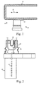
Figure 1 is a side view of a target and sensor, in accordance with the present invention; -
Figure 2 is a cutaway view of a sensor, in accordance with the present invention; -
Figure 3 is side cross sectional view of a target, in accordance with the present invention; -
Figure 4 is a top view of a schematic representation of a sensor and target having a graphical representation of magnetic flux patterns, in accordance with the present invention; -
Figure 5 is a graph representing the output of the sensor, in accordance with the present invention; -
Figure 6 is a side cross sectional view of an alternative embodiment of a target, in accordance with the present invention; -
Figure 7 is a graph representing the output of the sensor in conjunction with the target ofFigure 6 , in accordance with the present invention; -
Figure 8 is a side view of mounting system for a sensor and target, in accordance with the present invention. -
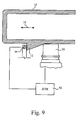
Figure 9 is a side view of a sensor and target system incorporating a calibration switch, in accordance with the present invention; -
Figure 10 is a perspective view of a dual target system, in accordance with the present invention; -
Figure 11 is a top view of a dual target system and corresponding sensors, in accordance with the present invention; -
Figure 12 is a perspective view of a target suitable for use in a rotary position sensor, in accordance with the present invention; and -
Figure 13 is a perspective view of a dual target system suitable for use in a rotary position sensor, in accordance with the present invention. - Reference throughout this specification to "one embodiment," "an embodiment," or similar language means that a particular feature, structure, or characteristic described in connection with the embodiment is included in at least one embodiment of the present invention. Thus, appearances of the phrases "in one embodiment," "in an embodiment," and similar language throughout this specification may, but do not necessarily, all refer to the same embodiment.
- Furthermore, the described features, advantages, and characteristics of the invention may be combined in any suitable manner in one or more embodiments. One skilled in the relevant art will recognize that the invention can be practiced without one or more of the specific features or advantages of a particular embodiment. In other instances, additional features and advantages may be recognized in certain embodiments that may not be present in all embodiments of the invention.
- Referring to
FIG. 1 , aposition sensor 10 may include atarget 12 and atransducer 14. The target may mount to anactive member 16, such as the plunger of an EGR valve, whose position is being measured. Theactive member 16 typically has at least one direction oftravel 18, which is translational in the embodiment ofFIG. 1 . Thetransducer 14 typically mounts to a stationary member such as an automobile body, an engine structure, or an EGR valve housing. Thetransducer 14 may also be mounted to a bracket that is secured to a stationary member. - Referring to
FIG. 2 , thetransducer 14 may include ahousing 20, aflux source 22, and afield sensing device 24. Theflux source 22 andfield sensing device 24 are secured to thehousing 20 such that agap 26 exists between them. In some embodiments, thehousing 20 surrounds theflux source 22 andfield sensing device 24 and is made of a material that has low interaction with magnetic fields such as a high-temperature plastic, ceramic, or a nonferromagnetic metal such as aluminum. In others, theflux source 22 andfield sensing device 24 are exposed. - The
flux source 22 may be embodied as a permanent magnet or as an electromagnet maintained at substantially constant or predictable magnetic flux. Aflux sensing device 24 may be embodied as a Hall-effect device. Alternatively, other magnetic-field sensors, such as spinvalve transistors based on the giant magnetoresistance (GMR) of magnetic multilayers, may be used to detect the magnetic field from theflux source 22.Wiring 32 couples to thefield sensing device 24 and provides ground, power, and output lines. Anintegral connector 34 secured to thehousing 20 or to the frame of the automobile proximate the housing may secure to a wiring harness or the like. Alternatively, a pigtail cable may be used. - In some embodiments, a
flux concentrator 36 extends from thefield sensing device 24, around thegap 26, to theflux source 22. Theflux concentrator 36 is typically made of a magnetically permeable material, such as magnetically soft iron. Theflux concentrator 36 may serve to intensify the magnetic flux incident on thefield sensing device 24. In some embodiments, anaperture 38 orgroove 38 is formed in theflux concentrator 36 to accommodate the wiring 30. - Referring to
FIG. 3 , thetarget 12 typically has a flux modulating property that varies along the direction oftravel 18. In the illustrated embodiment, the flux modulating property is the reluctance of the portion of thetarget 12 positioned within thegap 26. The reluctance may be varied by altering the cross section of thetarget 12 with position along the direction of travel, such that more or less material is positioned within thegap 26 depending on the position of thetarget 12. In the illustrated embodiment, theheight 40 of the target is varied. In other embodiments, the thickness is varied with position. In still other embodiments, two or more of thickness, height, and reluctance may be varied with position. In the illustrated embodiment, thetarget 12 has aslope 42 such that the amount of material within thegap 24 will vary linearly as thetarget 12 moves along the direction oftravel 18 at constant speed. - Referring to
FIG. 4 , in operation the magnetic flux from theflux source 22 will follow thepaths 50 in the absence of thetarget 12. However, as thetarget 12 moves into thegap 26, the reluctance across thegap 26 is reduced. Accordingly, flux will be directed alongpaths 52 through thetarget 12 and be incident on thefield sensing device 24. Additionally, thetarget 12 may comprise a soft magnetic material that in certain situations increases the total flux flowing out of theflux source 22. Thus, the greater the amount of material positioned within thegap 26, the greater will be the amount offlux paths 52 incident on thefield sensing device 24. - In order to accurately sense variations in the magnetic field, variations in
directions travel 18 may need to be reduced or compensated for. In some embodiments, theactive member 16 may be constrained to travel only in the direction oftravel 18. Where variation indirection 54 occurs the reluctance across thegap 26 is no longer varied only by the amount of material positioned within thegap 26. The reluctance across the air gaps is proportional to the inverse of the length of the air gaps. Accordingly, as the air gaps on either side of thetarget 12 are varied, nonlinear variation of the reluctance occurs. As variation in thedirection 56 occurs, the amount of material in thegap 26 no longer reflects variation along the direction oftravel 18 as determined by theslope 42 of thetarget 12, but rather by both theslope 42 and variation in thedirection 56. - Referring to
FIG. 5 , the output of thetransducer 14 as thetarget 12 is moved at constant speed is represented by thecurve 60. Although thecurve 60 is not a linear,portion 62 thereof is substantially linear and theend portions active member 16 may be limited to thelinear portion 62. Alternatively, calibration and digital processing may be used to compensate fornonlinear portions - Referring to
FIG. 6 , in some embodiments,multiple targets 12 may be used arranged in series along the direction oftravel 18. The output of such a target configuration is illustrated inFIG. 7 . An onboard computer may interpret the output by counting the number ofsloped regions 70 and substantiallyvertical regions 72 to determine both the direction of travel and the distance traveled. Within asingle period 74 the onboard computer may determine the position of thetarget 12 as for asingle target 12. - Referring to
Figure 8 , thetransducer 14 may secure to aflange 80 receiving one ormore fasteners 82, such as cap screws. Thefasteners 82 may secure theflange 80 to a stationary member such as the automobile body, engine structure, or EGR valve housing, or to a bracket or the like structure secured to a stationary member. Agroove 84 orgland 84 may be formed at the base of thehousing 20 to receive an O-ring, sealing the gap between the base of thehousing 20 to theflange 80, thereby preventing the entry of contaminants into thehousing 20. Theconnector 34 may extend from the flange oppositehousing 24 and secure to a wiring harness or the like. - Referring to
Figure 9 , in some embodiments, calibration may be facilitated by areference position switch 90. Areference position switch 90 may be positioned at the end points of the range of travel of theactive member 16, as in the illustrated embodiment. Alternatively, thereference position switch 90 may be placed at another position along the range of travel. Theswitch 90 may be activated by thetarget 14 as illustrated inFigure 9 . Alternatively, a separate structure may secure to theactive member 16 and activate theswitch 90. Theswitch 90 may be electrically coupled to theECM 92, or other on-board computer. - The ECM may use the output of the
switch 90 to calibrate thesensor 10. As shown inFigure 5 , the output of thesensor 10 is nonlinear. Accordingly, in order to compensate for nonlinearity computationally, the position on the curve must be known. A reference position switch may serve to establish a location on thecurve 60. In other embodiments, the switch may indicate that the active member is at the beginning of its range of travel. TheECM 92 may also use the known position of theswitch 90 to determine an offset to add to or subtract from output of thesensor 10 to compensate for any nonzero output of thesensor 10 at a position resulting from drift or other sources of bias. - Referring to
Figure 10 , in some embodiments of thesensor 10,multiple targets orthogonal directions target 12a may have a varied flux modulating property, such as a varied reluctance along the distance oftravel 18, as discussed hereinabove. Thetarget 12b may have a constant, or substantially constant, flux modulating property along the distance oftravel 18. - Referring to
Figure 11 ,multiple transducers targets active member 16 having theirgaps 26 positioned to interact with thetargets transducer 14b may provide a constant output signal, other than for variations due to drift and movement inorthogonal directions ECM 92 to normalize the output oftransducer 14a to compensate for such anomalies. - Referring to
Figure 12 , in some embodiments the direction oftravel 18 may be rotational rather than translational. In such embodiments, thetarget 12 may have a flux modulating property varying with change in angle about an axis ofrotation 92. Where the flux modulating property is reluctance as determined by the cross section of thetarget 12, theheight 40 of the target may vary with change in angular position. Atarget 12 may be embodied as atarget 12a used in conjunction with areference target 12b to compensate for movement other than along the direction of travel and for drift. - The present invention may be embodied in other specific forms without departing from its essential characteristics. The described embodiments are to be considered in all respects only as illustrative and not restrictive. The scope of the invention is, therefore, indicated by the appended claims rather than by the foregoing description. All changes which come within the definition of the claims are to be embraced within their scope.
Claims (16)
- An apparatus for detecting movement of a target (12), the apparatus comprising:a flux concentrator (36) comprising a material of high magnetic permeability, the flux concentrator (36) shaped to provide a magnetic gap (26) comprising a region of high magnetic reluctance;a magnetic flux source (22) coupled to the flux concentrator (36) and configured to establish a magnetic field across the magnetic gap (26);a magnetic sensor (24) positioned to measure the magnetic flux across the magnetic gap (26); anda target (12) having a cross-section that varies at least in one section monotonically with position in a direction of travel of the target (12), wherein the target (12) is configured to travel through the magnetic gap (26) and modulate the reluctance across the magnetic gap (26) in response to a change in travel distance of the target (12) along the direction of travel.
- The apparatus of claim 1, wherein the target (12) is formed of a low reluctance material.
- The apparatus of claim 1, wherein the magnetic sensor (24) is a Hall-effect device.
- The apparatus of claim 1, further comprising:an active member (16); anda guide secured to the active member (16) to permit motion thereof in a direction of travel;wherein the target (12) extends along the active member substantially parallel to the direction of travel and has a cross section varying along a direction perpendicular to the direction of travel; and
wherein the target (12) is positioned relative to the magnetic sensor (24) and the magnetic flux source (22) to interfere with the imposition of flux on the magnetic sensor (24). - The apparatus of claim 4, wherein the direction of travel is rotational, the cross section varying in the radial direction relative to the axis of rotation of the direction of travel.
- The apparatus of claim 4, wherein the direction of travel is translational.
- The apparatus of claim 6, wherein the cross section varies monotonically.
- The apparatus of claim 4, wherein the at least one magnetic flux source (22) is a permanent magnet.
- The apparatus of claim 1, further comprising:an EGR valve comprisinga cylinder securable to a vehicle, anda plunger positioned within the cylinder and slidable in a longitudinal direction in relation thereto;wherein the target (12) is coupled to the plunger and constrained to move in correspondence thereto, the target (12) having a cross section varying with change in position along at least one direction.
- The apparatus of claim 9, wherein the target (12) extends longitudinally along the plunger.
- The apparatus of claim 1, wherein the cross section of the target (12) varies monotonically in a radial direction.
- The apparatus of claim 1, further comprising an emission control module electrically coupled to the magnetic sensor (24).
- The apparatus of claim 1, wherein the flux concentrator couples the magnetic flux source (22) to the magnetic sensor (24).
- A method for detecting movement of a target (12), the method comprising:providing a flux concentrator (36) comprising a material of high magnetic permeability, the flux concentrator (36) defining a magnetic gap (26) comprising a region of high magnetic reluctance;establishing a magnetic field across the magnetic gap (26);measuring the magnetic flux across the magnetic gap (26);moving a target (12) through the magnetic gap (26), the target (12) having a cross-section that varies at least in one section monotonically with position in the direction of travel of the target (12); andmodulating the reluctance across the magnetic gap (26) in response to movement of the target (12) through the magnetic gap (26).
- The method of claim 14, wherein measuring the magnetic flux across the magnetic gap (26) comprises measuring an output signal from a control unit electrically coupled to a magnetic field sensing device.
- The method of claim 15, further comprising:providing a base position sensor proximate the target (12) and electrically coupled to the control unit, the sensor positioned to engage at least one of an active member and the target (12) at least one point along a range of motion thereof, wherein the target (12) is coupled to the active member;moving the active member to bring at least one of the active member and the target (12) into engagement with the base position sensor to cause activation thereof; andcalibrating the control unit upon activation of the base position sensor.
Applications Claiming Priority (2)
| Application Number | Priority Date | Filing Date | Title |
|---|---|---|---|
| US11/234,905 US7302940B2 (en) | 2005-09-26 | 2005-09-26 | Variable reluctance position sensor |
| PCT/US2006/037792 WO2007038657A2 (en) | 2005-09-26 | 2006-09-26 | Variable reluctance position sensor |
Publications (3)
| Publication Number | Publication Date |
|---|---|
| EP1929148A2 EP1929148A2 (en) | 2008-06-11 |
| EP1929148A4 EP1929148A4 (en) | 2011-01-05 |
| EP1929148B1 true EP1929148B1 (en) | 2016-11-30 |
Family
ID=37892358
Family Applications (1)
| Application Number | Title | Priority Date | Filing Date |
|---|---|---|---|
| EP06825195.8A Not-in-force EP1929148B1 (en) | 2005-09-26 | 2006-09-26 | Variable reluctance position sensor |
Country Status (4)
| Country | Link |
|---|---|
| US (1) | US7302940B2 (en) |
| EP (1) | EP1929148B1 (en) |
| CN (1) | CN101273194B (en) |
| WO (1) | WO2007038657A2 (en) |
Families Citing this family (14)
| Publication number | Priority date | Publication date | Assignee | Title |
|---|---|---|---|---|
| US7546827B1 (en) | 2008-08-21 | 2009-06-16 | Ford Global Technologie, Llc | Methods for variable displacement engine diagnostics |
| US8823366B2 (en) | 2009-11-16 | 2014-09-02 | Cts Corporation | Non-contacting sensor assembly |
| CN103038617A (en) * | 2010-05-14 | 2013-04-10 | Trw汽车美国有限责任公司 | Torque sensor assembly and method of manufacturing the same |
| TWI463160B (en) * | 2013-01-28 | 2014-12-01 | meng huang Lai | Planarized 3 dimensional magnetic sensor chip |
| US9772200B2 (en) * | 2013-03-15 | 2017-09-26 | Bourns, Inc. | Position measurement using angled collectors |
| CN103196414B (en) * | 2013-03-20 | 2015-05-27 | 无锡隆盛科技股份有限公司 | Detection tool for electric exhaust gas recirculation (EGR) valve angle transducer |
| JP6575771B2 (en) * | 2014-04-29 | 2019-09-18 | デーナ、オータモウティヴ、システィムズ、グループ、エルエルシー | Non-contact sensor for electromagnetic actuator assembly |
| JP2016109539A (en) * | 2014-12-05 | 2016-06-20 | Kyb株式会社 | Stroke sensor |
| WO2016196187A1 (en) | 2015-05-29 | 2016-12-08 | Dana Automotive Systems Group, Llc | An apparatus for sensing the position of an actuator assembly of a locking gearset |
| CN105222697A (en) * | 2015-10-23 | 2016-01-06 | 江门职业技术学院 | A kind of novel non-contact linear displacement transducer |
| CN105222698A (en) * | 2015-10-23 | 2016-01-06 | 江门职业技术学院 | A kind of linear displacement transducer based on becoming reluctance principle |
| CN108344878B (en) * | 2018-02-12 | 2020-06-09 | 西安航天动力研究所 | Large-signal small-size ultralow-temperature magnetoelectric speed sensor |
| US11009562B2 (en) * | 2018-08-03 | 2021-05-18 | Isentek Inc. | Magnetic field sensing apparatus |
| US11879754B2 (en) * | 2020-03-18 | 2024-01-23 | Tdk Corporation | Stroke sensor module, structure and method for mounting stroke sensor module |
Citations (1)
| Publication number | Priority date | Publication date | Assignee | Title |
|---|---|---|---|---|
| FR2845469A1 (en) * | 2002-10-07 | 2004-04-09 | Moving Magnet Tech | ANALOGUE POSITION SENSOR WITH VARIABLE RELUCTANCE |
Family Cites Families (23)
| Publication number | Priority date | Publication date | Assignee | Title |
|---|---|---|---|---|
| US3855525A (en) * | 1973-10-05 | 1974-12-17 | Illinois Tool Works | Angular velocity sensor |
| US5570015A (en) | 1992-02-05 | 1996-10-29 | Mitsubishi Denki Kabushiki Kaisha | Linear positional displacement detector for detecting linear displacement of a permanent magnet as a change in direction of magnetic sensor unit |
| CN1028055C (en) * | 1992-10-22 | 1995-03-29 | 浙江大学 | High Voltage Isolated Hall Effect Displacement Sensor |
| CN2142191Y (en) * | 1992-11-03 | 1993-09-15 | 杨文传 | Magnetic control sensor for measuring position |
| US5955881A (en) | 1994-10-18 | 1999-09-21 | Cts Corporation | Linkage position sensor having a magnet with two ramped sections for providing variable magnetic field |
| DE4440295A1 (en) | 1994-11-11 | 1996-05-15 | Vdo Schindling | Induction sensor for determining rpm in antilock system |
| AU3134597A (en) | 1996-05-20 | 1997-12-09 | Borg-Warner Automotive, Inc. | Automotive fluid control system with pressure balanced solenoid valve |
| JPH10221114A (en) * | 1997-02-10 | 1998-08-21 | Mitsubishi Electric Corp | Detector |
| JPH11304414A (en) * | 1998-04-21 | 1999-11-05 | Mitsubishi Electric Corp | Magnetic detector |
| US6095123A (en) | 1999-01-11 | 2000-08-01 | Ford Global Technologies, Inc. | Valve and valve control method |
| US6411081B1 (en) | 2000-02-10 | 2002-06-25 | Siemens Ag | Linear position sensor using magnetic fields |
| US6382195B1 (en) * | 2000-02-18 | 2002-05-07 | Borgwarner Inc. | Exhaust gas recirculation system for an internal combustion engine having an integrated valve position sensor |
| JP2002048506A (en) | 2000-08-04 | 2002-02-15 | Matsushita Electric Ind Co Ltd | Position sensor for electromagnetic actuator |
| US6415776B1 (en) * | 2000-08-25 | 2002-07-09 | Ford Global Technologies, Inc. | EGR system using pressure-based feedback control |
| US6374814B1 (en) | 2000-09-28 | 2002-04-23 | Siemens Canada Limited | Electric exhaust gas recirculation valve with integral position sensor and method of making |
| US6753680B2 (en) | 2000-11-29 | 2004-06-22 | Ronald J. Wolf | Position sensor |
| US6448763B1 (en) | 2001-01-10 | 2002-09-10 | Siemens Corporation | System for magnetization to produce linear change in field angle |
| US6565064B2 (en) | 2001-03-21 | 2003-05-20 | Delphi Technologies, Inc. | Model-based position control for a solenoid actuated valve |
| DE10143398A1 (en) * | 2001-09-04 | 2003-03-27 | Pierburg Gmbh | position sensor |
| JP3842644B2 (en) | 2001-11-19 | 2006-11-08 | 株式会社日本自動車部品総合研究所 | Displacement sensor |
| US6698408B2 (en) | 2002-07-10 | 2004-03-02 | Eaton Corporation | Position control strategy EGR valve actuator |
| FR2854691B1 (en) * | 2003-05-09 | 2005-07-08 | Siemens Vdo Automotive | NON-CONTACT HALL EFFECT ANGULAR POSITION SENSOR |
| US7124750B2 (en) * | 2003-10-31 | 2006-10-24 | Siemens Vdo Automotive Inc. | Relative position sensing for an exhaust gas recirculation valve |
-
2005
- 2005-09-26 US US11/234,905 patent/US7302940B2/en not_active Expired - Lifetime
-
2006
- 2006-09-26 WO PCT/US2006/037792 patent/WO2007038657A2/en not_active Ceased
- 2006-09-26 CN CN2006800342356A patent/CN101273194B/en not_active Expired - Fee Related
- 2006-09-26 EP EP06825195.8A patent/EP1929148B1/en not_active Not-in-force
Patent Citations (1)
| Publication number | Priority date | Publication date | Assignee | Title |
|---|---|---|---|---|
| FR2845469A1 (en) * | 2002-10-07 | 2004-04-09 | Moving Magnet Tech | ANALOGUE POSITION SENSOR WITH VARIABLE RELUCTANCE |
Also Published As
| Publication number | Publication date |
|---|---|
| CN101273194B (en) | 2011-07-06 |
| CN101273194A (en) | 2008-09-24 |
| EP1929148A4 (en) | 2011-01-05 |
| WO2007038657A2 (en) | 2007-04-05 |
| WO2007038657A3 (en) | 2007-12-27 |
| US7302940B2 (en) | 2007-12-04 |
| EP1929148A2 (en) | 2008-06-11 |
| US20070068499A1 (en) | 2007-03-29 |
Similar Documents
| Publication | Publication Date | Title |
|---|---|---|
| US7305966B2 (en) | Sensor module unit and a throttle apparatus equipped with the sensor module unit | |
| US7302940B2 (en) | Variable reluctance position sensor | |
| US5544000A (en) | Electric control apparatus | |
| US6382195B1 (en) | Exhaust gas recirculation system for an internal combustion engine having an integrated valve position sensor | |
| US5801529A (en) | Magnetoresistance sensing device without hystersis influence | |
| US7188021B2 (en) | Angular position sensor-based engine controller system | |
| JP3893907B2 (en) | Intake control device for internal combustion engine | |
| US5982171A (en) | Sensing device for detecting the angular displacement and relative position of a member of magnetic material | |
| US6883494B2 (en) | Intake air control apparatus for an engine | |
| US7019517B2 (en) | Offset magnet rotary position sensor | |
| JPH1073178A (en) | Linear motion operation device for control member | |
| US7124750B2 (en) | Relative position sensing for an exhaust gas recirculation valve | |
| US20180066964A1 (en) | Position detector with a minimum magnetic flux density position shifted from a center of a gap | |
| WO2006045186A1 (en) | Angular position sensor based engine controller system | |
| JP4494368B2 (en) | Electronically controlled throttle device | |
| EP1475525A2 (en) | Angle sensing device for electronic throttle valve control unit and method of production of said angle sensing device | |
| JP2014126551A (en) | Position detector | |
| US20040085061A1 (en) | Geartooth sensor with angled faced magnet | |
| AU758009B2 (en) | Distance measuring device | |
| US20140184208A1 (en) | Position detector | |
| US20090322315A1 (en) | Linear-movement sensor in an egr valve | |
| US20090295377A1 (en) | Contactless position sensor for vehicle | |
| JPH11141355A (en) | Opening detecting device of carbureter | |
| CN101368526B (en) | Ignition control carburetor for internal combustion engine | |
| KR20070063629A (en) | Non-contact rotary displacement sensor |
Legal Events
| Date | Code | Title | Description |
|---|---|---|---|
| PUAI | Public reference made under article 153(3) epc to a published international application that has entered the european phase |
Free format text: ORIGINAL CODE: 0009012 |
|
| 17P | Request for examination filed |
Effective date: 20080410 |
|
| AK | Designated contracting states |
Kind code of ref document: A2 Designated state(s): AT BE BG CH CY CZ DE DK EE ES FI FR GB GR HU IE IS IT LI LT LU LV MC NL PL PT RO SE SI SK TR |
|
| AX | Request for extension of the european patent |
Extension state: AL BA HR MK RS |
|
| A4 | Supplementary search report drawn up and despatched |
Effective date: 20101207 |
|
| RIC1 | Information provided on ipc code assigned before grant |
Ipc: G01B 7/30 20060101ALI20101201BHEP Ipc: H01L 43/06 20060101ALI20101201BHEP Ipc: F02B 47/08 20060101ALI20101201BHEP Ipc: G01D 5/14 20060101ALI20101201BHEP Ipc: F02M 25/07 20060101AFI20070604BHEP |
|
| DAX | Request for extension of the european patent (deleted) | ||
| 17Q | First examination report despatched |
Effective date: 20121221 |
|
| REG | Reference to a national code |
Ref country code: DE Ref legal event code: R079 Ref document number: 602006051100 Country of ref document: DE Free format text: PREVIOUS MAIN CLASS: F02M0025070000 Ipc: G01D0005200000 |
|
| RIC1 | Information provided on ipc code assigned before grant |
Ipc: G01D 5/20 20060101AFI20160429BHEP Ipc: F02M 26/48 20160101ALI20160429BHEP Ipc: F02M 26/54 20160101ALI20160429BHEP Ipc: F02M 26/72 20160101ALI20160429BHEP |
|
| GRAP | Despatch of communication of intention to grant a patent |
Free format text: ORIGINAL CODE: EPIDOSNIGR1 |
|
| INTG | Intention to grant announced |
Effective date: 20160623 |
|
| INTG | Intention to grant announced |
Effective date: 20160623 |
|
| GRAS | Grant fee paid |
Free format text: ORIGINAL CODE: EPIDOSNIGR3 |
|
| GRAA | (expected) grant |
Free format text: ORIGINAL CODE: 0009210 |
|
| AK | Designated contracting states |
Kind code of ref document: B1 Designated state(s): AT BE BG CH CY CZ DE DK EE ES FI FR GB GR HU IE IS IT LI LT LU LV MC NL PL PT RO SE SI SK TR |
|
| REG | Reference to a national code |
Ref country code: CH Ref legal event code: EP Ref country code: GB Ref legal event code: FG4D |
|
| REG | Reference to a national code |
Ref country code: AT Ref legal event code: REF Ref document number: 850236 Country of ref document: AT Kind code of ref document: T Effective date: 20161215 |
|
| REG | Reference to a national code |
Ref country code: IE Ref legal event code: FG4D |
|
| REG | Reference to a national code |
Ref country code: DE Ref legal event code: R096 Ref document number: 602006051100 Country of ref document: DE |
|
| PG25 | Lapsed in a contracting state [announced via postgrant information from national office to epo] |
Ref country code: LV Free format text: LAPSE BECAUSE OF FAILURE TO SUBMIT A TRANSLATION OF THE DESCRIPTION OR TO PAY THE FEE WITHIN THE PRESCRIBED TIME-LIMIT Effective date: 20161130 |
|
| REG | Reference to a national code |
Ref country code: LT Ref legal event code: MG4D |
|
| REG | Reference to a national code |
Ref country code: NL Ref legal event code: MP Effective date: 20161130 |
|
| REG | Reference to a national code |
Ref country code: AT Ref legal event code: MK05 Ref document number: 850236 Country of ref document: AT Kind code of ref document: T Effective date: 20161130 |
|
| PG25 | Lapsed in a contracting state [announced via postgrant information from national office to epo] |
Ref country code: GR Free format text: LAPSE BECAUSE OF FAILURE TO SUBMIT A TRANSLATION OF THE DESCRIPTION OR TO PAY THE FEE WITHIN THE PRESCRIBED TIME-LIMIT Effective date: 20170301 Ref country code: SE Free format text: LAPSE BECAUSE OF FAILURE TO SUBMIT A TRANSLATION OF THE DESCRIPTION OR TO PAY THE FEE WITHIN THE PRESCRIBED TIME-LIMIT Effective date: 20161130 Ref country code: LT Free format text: LAPSE BECAUSE OF FAILURE TO SUBMIT A TRANSLATION OF THE DESCRIPTION OR TO PAY THE FEE WITHIN THE PRESCRIBED TIME-LIMIT Effective date: 20161130 |
|
| PG25 | Lapsed in a contracting state [announced via postgrant information from national office to epo] |
Ref country code: PT Free format text: LAPSE BECAUSE OF FAILURE TO SUBMIT A TRANSLATION OF THE DESCRIPTION OR TO PAY THE FEE WITHIN THE PRESCRIBED TIME-LIMIT Effective date: 20170330 Ref country code: AT Free format text: LAPSE BECAUSE OF FAILURE TO SUBMIT A TRANSLATION OF THE DESCRIPTION OR TO PAY THE FEE WITHIN THE PRESCRIBED TIME-LIMIT Effective date: 20161130 Ref country code: PL Free format text: LAPSE BECAUSE OF FAILURE TO SUBMIT A TRANSLATION OF THE DESCRIPTION OR TO PAY THE FEE WITHIN THE PRESCRIBED TIME-LIMIT Effective date: 20161130 Ref country code: ES Free format text: LAPSE BECAUSE OF FAILURE TO SUBMIT A TRANSLATION OF THE DESCRIPTION OR TO PAY THE FEE WITHIN THE PRESCRIBED TIME-LIMIT Effective date: 20161130 Ref country code: FI Free format text: LAPSE BECAUSE OF FAILURE TO SUBMIT A TRANSLATION OF THE DESCRIPTION OR TO PAY THE FEE WITHIN THE PRESCRIBED TIME-LIMIT Effective date: 20161130 |
|
| PG25 | Lapsed in a contracting state [announced via postgrant information from national office to epo] |
Ref country code: NL Free format text: LAPSE BECAUSE OF FAILURE TO SUBMIT A TRANSLATION OF THE DESCRIPTION OR TO PAY THE FEE WITHIN THE PRESCRIBED TIME-LIMIT Effective date: 20161130 |
|
| PG25 | Lapsed in a contracting state [announced via postgrant information from national office to epo] |
Ref country code: CZ Free format text: LAPSE BECAUSE OF FAILURE TO SUBMIT A TRANSLATION OF THE DESCRIPTION OR TO PAY THE FEE WITHIN THE PRESCRIBED TIME-LIMIT Effective date: 20161130 Ref country code: SK Free format text: LAPSE BECAUSE OF FAILURE TO SUBMIT A TRANSLATION OF THE DESCRIPTION OR TO PAY THE FEE WITHIN THE PRESCRIBED TIME-LIMIT Effective date: 20161130 Ref country code: RO Free format text: LAPSE BECAUSE OF FAILURE TO SUBMIT A TRANSLATION OF THE DESCRIPTION OR TO PAY THE FEE WITHIN THE PRESCRIBED TIME-LIMIT Effective date: 20161130 Ref country code: DK Free format text: LAPSE BECAUSE OF FAILURE TO SUBMIT A TRANSLATION OF THE DESCRIPTION OR TO PAY THE FEE WITHIN THE PRESCRIBED TIME-LIMIT Effective date: 20161130 Ref country code: EE Free format text: LAPSE BECAUSE OF FAILURE TO SUBMIT A TRANSLATION OF THE DESCRIPTION OR TO PAY THE FEE WITHIN THE PRESCRIBED TIME-LIMIT Effective date: 20161130 |
|
| PG25 | Lapsed in a contracting state [announced via postgrant information from national office to epo] |
Ref country code: BG Free format text: LAPSE BECAUSE OF FAILURE TO SUBMIT A TRANSLATION OF THE DESCRIPTION OR TO PAY THE FEE WITHIN THE PRESCRIBED TIME-LIMIT Effective date: 20170228 Ref country code: IT Free format text: LAPSE BECAUSE OF FAILURE TO SUBMIT A TRANSLATION OF THE DESCRIPTION OR TO PAY THE FEE WITHIN THE PRESCRIBED TIME-LIMIT Effective date: 20161130 Ref country code: BE Free format text: LAPSE BECAUSE OF FAILURE TO SUBMIT A TRANSLATION OF THE DESCRIPTION OR TO PAY THE FEE WITHIN THE PRESCRIBED TIME-LIMIT Effective date: 20161130 |
|
| REG | Reference to a national code |
Ref country code: DE Ref legal event code: R097 Ref document number: 602006051100 Country of ref document: DE |
|
| PLBE | No opposition filed within time limit |
Free format text: ORIGINAL CODE: 0009261 |
|
| STAA | Information on the status of an ep patent application or granted ep patent |
Free format text: STATUS: NO OPPOSITION FILED WITHIN TIME LIMIT |
|
| 26N | No opposition filed |
Effective date: 20170831 |
|
| PG25 | Lapsed in a contracting state [announced via postgrant information from national office to epo] |
Ref country code: SI Free format text: LAPSE BECAUSE OF FAILURE TO SUBMIT A TRANSLATION OF THE DESCRIPTION OR TO PAY THE FEE WITHIN THE PRESCRIBED TIME-LIMIT Effective date: 20161130 |
|
| PGFP | Annual fee paid to national office [announced via postgrant information from national office to epo] |
Ref country code: GB Payment date: 20171227 Year of fee payment: 12 |
|
| PGFP | Annual fee paid to national office [announced via postgrant information from national office to epo] |
Ref country code: DE Payment date: 20171229 Year of fee payment: 12 |
|
| REG | Reference to a national code |
Ref country code: CH Ref legal event code: PL |
|
| PG25 | Lapsed in a contracting state [announced via postgrant information from national office to epo] |
Ref country code: MC Free format text: LAPSE BECAUSE OF FAILURE TO SUBMIT A TRANSLATION OF THE DESCRIPTION OR TO PAY THE FEE WITHIN THE PRESCRIBED TIME-LIMIT Effective date: 20161130 |
|
| REG | Reference to a national code |
Ref country code: IE Ref legal event code: MM4A |
|
| PG25 | Lapsed in a contracting state [announced via postgrant information from national office to epo] |
Ref country code: LU Free format text: LAPSE BECAUSE OF NON-PAYMENT OF DUE FEES Effective date: 20170926 |
|
| REG | Reference to a national code |
Ref country code: FR Ref legal event code: ST Effective date: 20180531 |
|
| PG25 | Lapsed in a contracting state [announced via postgrant information from national office to epo] |
Ref country code: LI Free format text: LAPSE BECAUSE OF NON-PAYMENT OF DUE FEES Effective date: 20170930 Ref country code: CH Free format text: LAPSE BECAUSE OF NON-PAYMENT OF DUE FEES Effective date: 20170930 Ref country code: IE Free format text: LAPSE BECAUSE OF NON-PAYMENT OF DUE FEES Effective date: 20170926 |
|
| PG25 | Lapsed in a contracting state [announced via postgrant information from national office to epo] |
Ref country code: FR Free format text: LAPSE BECAUSE OF NON-PAYMENT OF DUE FEES Effective date: 20171002 |
|
| REG | Reference to a national code |
Ref country code: DE Ref legal event code: R119 Ref document number: 602006051100 Country of ref document: DE |
|
| GBPC | Gb: european patent ceased through non-payment of renewal fee |
Effective date: 20180926 |
|
| PG25 | Lapsed in a contracting state [announced via postgrant information from national office to epo] |
Ref country code: HU Free format text: LAPSE BECAUSE OF FAILURE TO SUBMIT A TRANSLATION OF THE DESCRIPTION OR TO PAY THE FEE WITHIN THE PRESCRIBED TIME-LIMIT; INVALID AB INITIO Effective date: 20060926 |
|
| PG25 | Lapsed in a contracting state [announced via postgrant information from national office to epo] |
Ref country code: DE Free format text: LAPSE BECAUSE OF NON-PAYMENT OF DUE FEES Effective date: 20190402 |
|
| PG25 | Lapsed in a contracting state [announced via postgrant information from national office to epo] |
Ref country code: GB Free format text: LAPSE BECAUSE OF NON-PAYMENT OF DUE FEES Effective date: 20180926 Ref country code: CY Free format text: LAPSE BECAUSE OF NON-PAYMENT OF DUE FEES Effective date: 20161130 |
|
| PG25 | Lapsed in a contracting state [announced via postgrant information from national office to epo] |
Ref country code: TR Free format text: LAPSE BECAUSE OF FAILURE TO SUBMIT A TRANSLATION OF THE DESCRIPTION OR TO PAY THE FEE WITHIN THE PRESCRIBED TIME-LIMIT Effective date: 20161130 |
|
| PG25 | Lapsed in a contracting state [announced via postgrant information from national office to epo] |
Ref country code: IS Free format text: LAPSE BECAUSE OF FAILURE TO SUBMIT A TRANSLATION OF THE DESCRIPTION OR TO PAY THE FEE WITHIN THE PRESCRIBED TIME-LIMIT Effective date: 20170330 |
|
| P01 | Opt-out of the competence of the unified patent court (upc) registered |
Effective date: 20230510 |