EP1927881A1 - Optical block with variable polarizing characteristics and method for generating different states of polarization using said block - Google Patents
Optical block with variable polarizing characteristics and method for generating different states of polarization using said block Download PDFInfo
- Publication number
- EP1927881A1 EP1927881A1 EP06124924A EP06124924A EP1927881A1 EP 1927881 A1 EP1927881 A1 EP 1927881A1 EP 06124924 A EP06124924 A EP 06124924A EP 06124924 A EP06124924 A EP 06124924A EP 1927881 A1 EP1927881 A1 EP 1927881A1
- Authority
- EP
- European Patent Office
- Prior art keywords
- optical
- block
- polarization
- birefringent
- plates
- Prior art date
- Legal status (The legal status is an assumption and is not a legal conclusion. Google has not performed a legal analysis and makes no representation as to the accuracy of the status listed.)
- Withdrawn
Links
- 230000003287 optical effect Effects 0.000 title claims abstract description 144
- 230000010287 polarization Effects 0.000 title claims abstract description 99
- 238000000034 method Methods 0.000 title claims description 10
- 230000004044 response Effects 0.000 claims description 14
- 230000009021 linear effect Effects 0.000 claims description 6
- 238000001514 detection method Methods 0.000 claims description 4
- 238000006243 chemical reaction Methods 0.000 claims description 3
- 230000007423 decrease Effects 0.000 claims description 2
- 239000011521 glass Substances 0.000 claims description 2
- 238000012545 processing Methods 0.000 claims description 2
- 239000013598 vector Substances 0.000 description 21
- 239000011159 matrix material Substances 0.000 description 17
- 230000001419 dependent effect Effects 0.000 description 10
- 230000008859 change Effects 0.000 description 9
- 230000005540 biological transmission Effects 0.000 description 5
- 238000010586 diagram Methods 0.000 description 5
- 238000005259 measurement Methods 0.000 description 5
- RKTYLMNFRDHKIL-UHFFFAOYSA-N copper;5,10,15,20-tetraphenylporphyrin-22,24-diide Chemical compound [Cu+2].C1=CC(C(=C2C=CC([N-]2)=C(C=2C=CC=CC=2)C=2C=CC(N=2)=C(C=2C=CC=CC=2)C2=CC=C3[N-]2)C=2C=CC=CC=2)=NC1=C3C1=CC=CC=C1 RKTYLMNFRDHKIL-UHFFFAOYSA-N 0.000 description 3
- 239000000523 sample Substances 0.000 description 3
- 238000012360 testing method Methods 0.000 description 3
- 230000035945 sensitivity Effects 0.000 description 2
- 230000001131 transforming effect Effects 0.000 description 2
- 238000012512 characterization method Methods 0.000 description 1
- 230000005684 electric field Effects 0.000 description 1
- 238000005516 engineering process Methods 0.000 description 1
- 238000003780 insertion Methods 0.000 description 1
- 230000037431 insertion Effects 0.000 description 1
- 230000003993 interaction Effects 0.000 description 1
- 239000000463 material Substances 0.000 description 1
- 230000001902 propagating effect Effects 0.000 description 1
- 239000010453 quartz Substances 0.000 description 1
- 230000009467 reduction Effects 0.000 description 1
- VYPSYNLAJGMNEJ-UHFFFAOYSA-N silicon dioxide Inorganic materials O=[Si]=O VYPSYNLAJGMNEJ-UHFFFAOYSA-N 0.000 description 1
Images



Classifications
-
- G—PHYSICS
- G01—MEASURING; TESTING
- G01M—TESTING STATIC OR DYNAMIC BALANCE OF MACHINES OR STRUCTURES; TESTING OF STRUCTURES OR APPARATUS, NOT OTHERWISE PROVIDED FOR
- G01M11/00—Testing of optical apparatus; Testing structures by optical methods not otherwise provided for
- G01M11/30—Testing of optical devices, constituted by fibre optics or optical waveguides
- G01M11/33—Testing of optical devices, constituted by fibre optics or optical waveguides with a light emitter being disposed at one fibre or waveguide end-face, and a light receiver at the other end-face
- G01M11/337—Testing of optical devices, constituted by fibre optics or optical waveguides with a light emitter being disposed at one fibre or waveguide end-face, and a light receiver at the other end-face by measuring polarization dependent loss [PDL]
-
- G—PHYSICS
- G01—MEASURING; TESTING
- G01J—MEASUREMENT OF INTENSITY, VELOCITY, SPECTRAL CONTENT, POLARISATION, PHASE OR PULSE CHARACTERISTICS OF INFRARED, VISIBLE OR ULTRAVIOLET LIGHT; COLORIMETRY; RADIATION PYROMETRY
- G01J4/00—Measuring polarisation of light
- G01J4/04—Polarimeters using electric detection means
-
- G—PHYSICS
- G01—MEASURING; TESTING
- G01M—TESTING STATIC OR DYNAMIC BALANCE OF MACHINES OR STRUCTURES; TESTING OF STRUCTURES OR APPARATUS, NOT OTHERWISE PROVIDED FOR
- G01M11/00—Testing of optical apparatus; Testing structures by optical methods not otherwise provided for
- G01M11/30—Testing of optical devices, constituted by fibre optics or optical waveguides
- G01M11/33—Testing of optical devices, constituted by fibre optics or optical waveguides with a light emitter being disposed at one fibre or waveguide end-face, and a light receiver at the other end-face
-
- G—PHYSICS
- G02—OPTICS
- G02B—OPTICAL ELEMENTS, SYSTEMS OR APPARATUS
- G02B27/00—Optical systems or apparatus not provided for by any of the groups G02B1/00 - G02B26/00, G02B30/00
- G02B27/28—Optical systems or apparatus not provided for by any of the groups G02B1/00 - G02B26/00, G02B30/00 for polarising
- G02B27/283—Optical systems or apparatus not provided for by any of the groups G02B1/00 - G02B26/00, G02B30/00 for polarising used for beam splitting or combining
Definitions
- the present invention relates to generating optical signals with defined polarization states.
- a set of probing signals with defined polarization states is commonly used.
- Such polarization states might be generated by means of a polarization controller, such as the Agilent 8169A Polarization Controller.
- This polarization controller allows for providing probe signals at precisely synthesized states of polarization.
- the response signals returning from the DUT allows for determining optical properties of a DUT.
- Information about the Agilent 8169A Polarization Controller can be drawn from the technical specifications available at Product or Service Web Pages of Agilent Technologies Inc. or from patent application with the publication number US 2004/0067062 A1 or patent application PCT/EP2005/056021 of the same applicant.
- Different methods are known for determining optical properties the DUT.
- probing signals at four precisely synthesized, e.g. tetragonal states of polarization are provided to the DUT and the power of the optical signals returning from the DUT are detected.
- the elements of so-called Mueller Matrix are determined.
- optical properties of the DUT e.g. the minimum and maximum insertion loss, polarization dependent loss (PDL), the group delay (GD) or the differential group delay (DGD) can be derived.
- PDL polarization dependent loss
- GD group delay
- DTD differential group delay
- the so called Jones matrix method is known, wherein the optical properties are derived by measuring the output states of polarization of the signals returning from the DUT for at least two, preferably orthogonal states of polarization.
- the Mueller method might be applied by applying a set of six, preferably orthogonal states of polarization.
- polarisation controllers One problem of polarisation controllers known in the art is that while changing the wavelength of an input signal of the polarisation controller, the SOP system does not remain constant. Depending on the settings of the polarization controller, undesired changes of the SOP system over a regarded wavelength range may occur. It is known to use so-called achromatic wave plates showing a reduced dependency from the wavelength in a certain range. However, such wave plates are complex and expensive, and reduction of wavelength dependency might not be sufficient over the whole required wavelength range.
- Each state of polarization (SOP) of the polarization controller can be regarded as a vector in a Stokes space.
- the end points of the different vectors set by the polarization controller further also referred to as SOP system, span a geometric shape.
- the geometric shape is a line (two endpoints), a triangle (three endpoints) or a polyhedron (more that three endpoints).
- the polyhedron is a tetrahedron comprising four end points and four triangular faces.
- a regular tetrahedron is a tetrahedron with four equal triangular faces.
- the invention is based on the insight that the absolute change of an SOP system within the Stokes space over the wavelengths is often of low relevance, as long as the geometric shape does not significantly change, i.e. variations of the relative orientations of the Stokes vectors to each other do not significantly change over the wavelength.
- Aforementioned patent application PCT/EP2005/056021 discloses a controlling of a polarization controller with individually rotatable quarter and half waveplates so that variations of the shape of the polyhedron spanned by the SOP system are kept below a desired value while varying the wavelength of the input light.
- an optical apparatus for receiving an incident optical beam and generating a set of output beams having different states of polarization.
- the optical apparatus thereby comprises an optical block, the optical block further comprising a first birefringent plate and a second birefringent plate, whereby both plates have a fixed position to each other and are positioned optically in series with respect to the propagation direction of the incident optical beam.
- the widths of the first and the second birefringent plate are varying along a first lateral direction with respect to the propagation direction of the optical beam the first and second plates have each birefringent properties, whereby the main optical axes of said plates have different orientations.
- the optical block is arranged to receive the incident optical beam at a plurality of different positions relative to the first lateral direction, so that a plurality of output optical beams having different states of polarization are provided.
- the optical block and a light transmitter being adapted for providing the incident optical beam are movable relative to each other along the first lateral direction; in other words, the optical block is movable relative to the incident light beam.
- the birefringent plates are arranged being serially passed through by the light beam, whereby the plates have a fixed position to each other and each show a variable width with respect to a lateral position (x-axis) in view of the propagation direction of the light beam (z-axis), so that a corresponding lateral movement leads to an intersection at positions with different widths of the birefringent plates.
- the optical block is movable, relative to the incident beam, (at least) laterally in the direction, in which the widths vary.
- the movement direction of the optical block thereby might have as well components in direction of the beam axis (x-axis) and/or laterally vertical to the lateral direction of plate widths variations (z-axis).
- the first and second birefringent plates are wedge shaped, so that the plate widths increase or decrease linearly in dependence of the position along the first lateral direction.
- the orientation of the main axes with respect to the light beam and the widths variations are designed such that, while moving the optical block relative to the incident beam, the polarization of the output beam of the polarization controller follows a spiral-form trajectory within the Stokes space.
- the outer surfaces of the first and the second plates being passed by the optical beam are substantially parallel to each other and orthogonal with respect to the optical beam, and the inner surface of the first plate and the inner surface of the second plate being passed by the optical beam have a first and second angle with respect to the first lateral direction, therewith showing a first and second slope respectively.
- the angle between the light beam and the orientation of the main axis of the first birefringent plate is chosen about 59 degree
- the angle between the light beam and the orientation of the main axis of the second birefringent plate is chosen about 10 degree
- the ratio of the first slope and second slope is chosen to be about 1/2,55.
- the optical block is controlled to be moved to distinct lateral positions in order to generate a set of beams with precisely synthesized polarizations being significantly different in order to obtain optimum DUT characterization results.
- the optical block is controlled to be moved to four distinct lateral positions in order to generate a set of light beams with state of polarizations forming a substantially regular tetrahedral SOP system.
- the optical block comprises an optical carrier, preferably of glass, connecting the inner surfaces of the first and the second birefringent block.
- the optical block is mechanically connected to a linear drive in order to provide a lateral movement of the optical block.
- the optical block might be mounted to be rotatable around a rotational axis being substantially perpendicular to the optical beam, if being moved by a rotational drive.
- the polarization controller comprises a control circuit for controlling the drive to move the optical block into determined positions, e.g. four distinct positions for generate a set of Stokes vectors spanning a regular polyhedron.
- the four distinct positions are chosen such that the variation of a volume of the polyhedron spanned by the corresponding states of polarizations is at least one of: below 12 percent, while varying the wavelength of the input signal within a wavelength rage between 1250 - 1650 nanometer, and below 4 percent, while varying the wavelength of the input signal within a wavelength rage between 1300 - 1500 nanometer.
- the polarization controller comprises a user interface for receiving at least one of the following parameters: the wavelength range, the number of states of polarization, the geometric shape of the SOP system, and a merit function representing a maximum value of shape variation over the wavelength, e.g. the change of volume of a chosen polyhedron.
- merit functions might be defined, e.g. a function representing a mean variation of a sum of the angles between the Stokes vectors over the wavelength range, a maximum variation of any angle between the Stokes vectors over the wavelength range, a mean variation of the polyhedron volume over the wavelength range, if the number of states of polarization is greater than 3, or a mean or maximum variation of the polyhedron volume over the wavelength range, if the number of states of polarization is greater than 3. It is apparent the merit functions listed above only serve as examples.
- retardance errors of the wave plates over the wavelength are at least partly converted into a slow rotation of the complete SOP-system, whereby the change of the shape spanned by the SOP vectors over wavelength is below a determined limit.
- shape changes affect noise and sensitivity to measurement errors like detector PDL, the invention allows for significantly reducing such errors.
- the apparatus further comprises a polarizing circuit, a detector circuit being arranged in optical series behind the optical block and an analyzer.
- the polarizing circuit provides a polarization to the plurality of output optical beams of the optical block, thereby generating a set of polarized optical beams having different optical powers.
- the detection circuit receives the set of polarized output beams provides an opto-electrical conversion to the beams of said set, and provides a corresponding set of electrical signals to the analyzer.
- the analyzer determines a polarization property of the incident optical beam therefrom.
- the detector circuit might be a single element receiving the different beams being output by the optical block sequentially.
- the detector circuit might comprise a plurality of detector elements, each being positioned at selected positions along the first lateral position (x-axis) behind the output surface of the optical block.
- the apparatus further comprises means for receiving a DUT in order to provide the DUT with the set of output optical beams being output from the optical block.
- the detector circuit receives response beams from the DUT being generated in response to the optical output beams, and generates a set of electrical signal having amplitudes corresponding each the optical power of the response signals.
- the analyzer receives the set of electrical signals and determines a DUT property therefrom.
- Embodiments of the invention can be partly or entirely embodied or supported by one or more suitable software programs, which can be stored on or otherwise provided by any kind of data carrier, and which might be executed in or by any suitable data processing unit.
- Fig. 1a shows a block diagram of a first setup for determining optical properties of a DUT, comprising a polarization controller according to the invention
- Fig. 1b shows a block diagram of a measurement setup for determining a polarization property of an incident light, comprising a polarization controller according to the invention
- Fig. 2 shows a more detailed three dimensional view of the polarization controller of Fig. 1 ,
- Fig. 3 shows a top view of the polarization controller according to Fig.2 and a table of exemplary dimension values
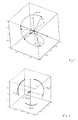
- Fig. 4 shows a representation of a trajectory of the polarization state of an output light of the polarization controller in dependence on a setting of the polarization controller in a Poincar6 sphere, and a set of four exemplary states of polarization chosen from the trajectory,
- Fig. 5 shows a representation of four trajectories pertinent to the chosen states of polarization in dependence on the wavelength of the incident light
- Fig. 6 shows angle variations over wavelength of angles between stokes vectors of an exemplary tetrahedral SOP system, and a corresponding relative volume variation over wavelength of the chosen states of polarization.
- Fig. 1a shows a first setup for determining optical properties of an optical device under test (DUT) 3.
- a light source preferably a tunable laser source, generates an input beam L1, whereby the input light L1 might have a known state of polarization.
- Said input beam L1 is provided to a polarization controller 2, which provides a polarization controller output beam or probe signal L2 to be provided to the DUT 3, thereby transforming, dependent on a setting of the polarization controller, the input state into one of a set of different output states of polarization, e.g. one of a set of four tetragonal polarization states for performing a four states Mueller Matrix method.
- the DUT 3 emits response signals L3 respectively.
- the response signals L3 might be generated by transmission through the DUT 3, by reflection from the DUT 3 or by a combined transmission and reflection.
- the DUT response signals L3 are provided to an optical detection circuit 4, which determines an optical power of each the response signals L3, and generates corresponding electrical signals E1, each having a current or voltage value being dependent, e.g. proportional, with relation the corresponding optical power.
- a corresponding signal power is determined to be provided to a DUT property analyzer 5.
- the DUT property analyzer 5 determines a polarization dependent loss PDL, an intensity loss IL, a group delay GD or a differential group delay DGD of the DUT 3 by applying the above-mentioned Mueller Matrix method.
- the relationship between the various polarization states on the one hand and the corresponding set of signal powers on the other hand allows getting an indication of the DUT's optical behavior.
- a tunable laser source is used as a light source 1
- wavelength sweeps of the light signal 2 over a certain wavelength range might be performed. This allows recording the DUT's optical properties over the swept wavelength range.
- the polarization controller 2 comprises a movable optical block 21, a drive 22 and a drive controller 23.
- Fig. 1b shows a second setup comprising the polarization controller 2 of Fig. 1a , for determining a polarization property of an incident light, e.g. the state of polarization, which might not be known or which might to be asserted, generated by way of example by the same light source 1 of Fig. 1a .
- the input beam L1 generated by the light source 1 is provided to the polarization controller 2, which provides a polarization controller output beams L2, thereby transforming, dependent on a setting of the polarization controller, the input state into different output states of polarization.
- the output beams L2 having different states of polarization are provided to a polarizer (or polarization filter) 6.
- the polarizer 6 generates a set of polarized beams L6 from the output beams L2, whereby each of the polarized beams of said set L6 shows an optical power being dependent on the state of polarization of the corresponding output beam.
- the polarized beams are provided to a detection circuit 7 that provides an opto-electrical conversion to the polarized beams L6 and provides corresponding electrical signals E2 to a light beam analyzing circuit 8.
- the light beam analyzing circuit 8 determines a state of polarization of the incident light beam L1.
- Fig. 2 shows the polarization controller 2 in more details.
- the movable block 21 comprises an optical carrier 213 carrying a first birefringent plate 211 at a first surface and a second birefringent plate 212 at a second surface opposite to the first surface.
- the optical carrier 213 does not have birefringent behavior, so that it does not change the polarization of the beam traveling through.
- the optical carrier serves for maintaining a fixed position of the birefringent plates to each other and to the drive.
- any other carrier i.e. a supporting plate with the plates 211 and 212 being mounted upon, can being can be used.
- Birefringent plates are also known as retardation plates, being optical elements with two principal or main axes, one slow axis and one fast axis that resolve an incident polarized beam into two mutually perpendicular polarized beams. Their operation is based on birefringent linear effect, which is the difference in the refractive indices for the beams with parallel and normal polarization towards the optical axis of the crystalline quartz material being within the wave plate plane. The emerging beam recombines to form a particular single polarized beam.
- Polarization controllers known in the art often comprises a combination of a so-called half wave plate and a so-called quarter wave plate, whereby both have fixed thicknesses.
- the thickness of the half wave plate thereby is chosen such that the phase difference is one half of the wavelength (zero-order wave plate) or defined multiples of one half of the wavelength (multi-order wave plates).
- a linearly polarized beam incident on a half wave plate emerges as a linearly polarized beam but rotates such that its angle to the optical axis is twice that of the incident beam.
- the thickness of the so-called quarter wave plate thereby is chosen such that the phase difference is one quarter of the wavelength (zero-order wave plate) or defined multiples of one quarter of the wavelength (multi-order wave plates). If the angle q between the electric field vector of an incident linearly polarized beam and the principal plane of the quarter wave plate is 45, the emergent beam is circularly polarized.
- the plates 211 and 212 each have a varying width or thickness in direction of the first lateral direction x with respect to the propagating direction z of the incident beam L1.
- the birefringent plates 211 and 212 each have each birefringent property, whereby the main optical axes, e.g. both so-called fast axes, of said plates have different orientations with respect to the optical beam L1.
- the angle between the light beam and the orientation of the fast axis of the first birefringent plate is chosen about 59 degree
- the angle between the light beam and the orientation of the fast axis of the second birefringent plate is chosen about 10 degree.
- the movable optical block 21, in the following also being referred to as block 21, is mechanically connected to the drive 22 that moves the block 21 along the first lateral direction x with respect to the optical beam L1, so that the optical beam L1 passes though different widths of the first and the second birefringent plates 211 and 212, dependent on the lateral position x of the block 21.
- the first and second birefringent plates 211 and 212 have wedge shaped forms, so that the widths being passed through by the optical beam L1 vary linearly when moving the block 21.
- the outer surfaces of the first and the second plates 211 and 212, representing the optical input and an optical output respectively of the polarization controller are preferably parallel to each other and orthogonal with respect to the optical beam.
- the inner surface of the first plate 211 is inclined by a first inclination angle ⁇ 1 and the inner surface of the second plate 212 is inclined by a second inclination angle ⁇ 2 having opposite signs and being generally different in their absolute values.
- the widths of both plates increase in the first lateral direction x.
- the optical behavior of the DUT 3 can be described by means of the aforementioned Mueller matrix M, which is a 4 x 4 real matrix. Any equivalent matrix that represents the DUT's optical properties, e.g. a Jones matrix, can be used as well.
- a Stokes vector S (S0, S1, S2, S3) completely describes the power and polarization state of an optical wave, whereby S0 denotes the total intensity, S1 indicates the degree of linear horizontal (S1 > 0) or vertical polarization (S1 ⁇ 0), S2 indicates the degree of linear +45° (S2 > 0) or -45° (S2 ⁇ 0) polarization, and S3 corresponds to the degree of right-hand circular (S3 > 0) or left-hand circular (S3 ⁇ 0) polarization.
- the Mueller matrix elements m 1k correspond to the first row of the Mueller matrix M.
- the elements m 11 , m 12 , m 13 , m 14 of the Mueller matrix four different well-defined states of polarization S a ,S b ,S c ,S d are consecutively applied to the device under test, and the signal powers of the corresponding DUT response signals are measured.
- the Mueller matrix elements m 11 , m 12 , m 13 , m 14 are known, a multitude of optical properties of the DUT can be derived there from.
- the Mueller matrix element m 11 indicates the "average loss" of the DUT.
- the minimum transmission T min and the maximum transmission T max can be obtained as
- T min m 11 - m 12 2 + m 13 2 + m 14 2
- T max m 11 + m 12 2 + m 13 2 + m 14 2
- the polarization dependent loss (PDL) can be determined as:
- optical properties can be derived from the elements of the first row of the Mueller matrix.
- the movable block 21 is controlled to be moved to corresponding distinct lateral positions.
- the polarizations of the set of polarizations are significantly different to each other. Therefore, a set of four polarization states forming a tetragonal polarization system in the so-called Poincaré sphere.
- the endpoints of the four Stokes vectors S a , S b , S c , S d define a regular tetrahedron, which is the most symmetric spherical geometric shape of four points.
- Fig. 3 on the left hand side, therefore shows a top view of the block 21 showing the width d1(x) and d2(x) for four corresponding lateral positions x 1 , x 2 , x 3 , x 4 .
- the block 21 is therefore being driven to move sequentially to those positions. Therefore the drive 22 receives a corresponding control signal C1 form the controlling circuit 23.
- the angle between the light beam and the orientation of the fast axis of the first birefringent plate is chosen about 59 degree
- the angle between the light beam and the orientation of the fast axis of the second birefringent plate is chosen about 10 degree.
- the inner surface of the first plate by way of example shows a slope of 100 micrometer over the length of the block in by way of example positive direction of the first lateral direction (e.g. 20 millimeter) and the inner surface of the second plate shows a slope of 255 micrometer in the same direction. This results in a slope ratio of 1:2,55.
- Fig 3 shows a table with corresponding values in micrometer of the widths d1 and d2 of the first and second plates 211 and 212 at the positions x 1 , x 2 , x 3 , x 4 .
- Fig. 4 shows a representation of the set of resulting polarization states S a , S b , S c , S d in a Poincaré sphere.
- the four Stokes vectors are lying on a trajectory TR(x).
- the trajectory TR represents a variation of the polarization dependent on the position x of the block 21 with respect to the beam L1.
- the endpoints of the four Stokes vectors S a , S b , S c , S d are chosen to define a substantially regular tetrahedron.
- Fig. 5 shows a representation of a set of trajectories TR a ( ⁇ ), TR b ( ⁇ ), TR c ( ⁇ ), TR d ( ⁇ ) in the Poincaré sphere showing the variation of the polarization states S a , S b , S c , S d over the wavelength ⁇ within a range from 1250 nanometer to 1650 nanometer. Due to the properly chosen dimensions of the plates and orientation of the main axes as described under Fig. 3 , a variation the wavelength leads to a slow rotation of the tetrahedron defined by the Stokes vectors, whereby the change of the shape of the tetrahedron is rather small, being described in the following.
- Fig. 6 in the upper part a) shows a diagram with values in degree of the six relative angles ⁇ 12, ⁇ 13, ⁇ 14, ⁇ 23, ⁇ 24, ⁇ 34 between the Stokes vectors S a , S b , S c and S d over wavelength within a range between 1250 nanometer (nm) and 1650 nm.
- the Stokes vectors result from the movable block example described under Fig. 3 .
- the variation of any angle is below 50 degree over the whole wavelength range between 1250 nm and 1650 nm and far below, if a sub-range, e.g. a wavelength range between 1350 nm and 1550 nm is regarded.
- Fig. 6 in the lower part shows a diagram of a corresponding relative volume variation over a wavelength range between 1250 nm and 1650 nm for the above-described SOP system.
- the following formula describes the volume as a function of the wavelength ⁇ spanned by the vectors S a -S d :
- V ⁇ 1 / 6 ⁇ S d ⁇ - S a ⁇ ⁇ x ⁇ S c ⁇ - S a ⁇ ⁇ S b ⁇ - S a ⁇
- the variation of a volume of the tetrahedron spanned by the corresponding states is an indication of the stability of the tetrahedron over wavelength. As shown here, this variation is below 12 percent, while varying the wavelength of the input signal within a wavelength rage between 1250 -1650 nm, and below 5 percent, while varying the wavelength of the input signal within the sub wavelength rage between 1350 - 1550 nm.
- wavelength variations lead to slow rotations of the SOP-system, whereby the change of the shape spanned by the SOP vectors over wavelength is kept small.
- This allows for using such polarization controller for rather precise polarization characteristics measurements of a DUT over a wide wavelength ranges.
- shape changes affect noise and sensitivity to measurement errors like detector PDL, the invention allows for minimizing such errors.
Landscapes
- Physics & Mathematics (AREA)
- General Physics & Mathematics (AREA)
- Optics & Photonics (AREA)
- Chemical & Material Sciences (AREA)
- Analytical Chemistry (AREA)
- Spectroscopy & Molecular Physics (AREA)
- Mechanical Light Control Or Optical Switches (AREA)
Abstract
Description
- The present invention relates to generating optical signals with defined polarization states.
- For determining optical properties of an optical device under test (DUT), a set of probing signals with defined polarization states is commonly used. Such polarization states might be generated by means of a polarization controller, such as the Agilent 8169A Polarization Controller. This polarization controller allows for providing probe signals at precisely synthesized states of polarization. The response signals returning from the DUT allows for determining optical properties of a DUT. Information about the Agilent 8169A Polarization Controller can be drawn from the technical specifications available at Product or Service Web Pages of Agilent Technologies Inc. or from patent application with the publication number
US 2004/0067062 A1 or patent applicationPCT/EP2005/056021 - Different methods are known for determining optical properties the DUT. According to the so-called Mueller Method, probing signals at four precisely synthesized, e.g. tetragonal states of polarization are provided to the DUT and the power of the optical signals returning from the DUT are detected. From the known input states of polarization and the measured signal powers, the elements of so-called Mueller Matrix are determined. From elements of this Matrix, optical properties of the DUT, e.g. the minimum and maximum insertion loss, polarization dependent loss (PDL), the group delay (GD) or the differential group delay (DGD) can be derived.
- Alternatively the so called Jones matrix method is known, wherein the optical properties are derived by measuring the output states of polarization of the signals returning from the DUT for at least two, preferably orthogonal states of polarization. In a further alternative a variant of the Mueller method might be applied by applying a set of six, preferably orthogonal states of polarization.
- One problem of polarisation controllers known in the art is that while changing the wavelength of an input signal of the polarisation controller, the SOP system does not remain constant. Depending on the settings of the polarization controller, undesired changes of the SOP system over a regarded wavelength range may occur. It is known to use so-called achromatic wave plates showing a reduced dependency from the wavelength in a certain range. However, such wave plates are complex and expensive, and reduction of wavelength dependency might not be sufficient over the whole required wavelength range.
- It is an object of the invention to provide an improved generating of optical signals with defined polarization states. The object is solved by the independent claims. Further embodiments are shown by the dependent claims.
- Each state of polarization (SOP) of the polarization controller can be regarded as a vector in a Stokes space. The end points of the different vectors set by the polarization controller, further also referred to as SOP system, span a geometric shape. Depending on the number of endpoints, the geometric shape is a line (two endpoints), a triangle (three endpoints) or a polyhedron (more that three endpoints).
- For the case of four states of polarization used for the above-mentioned Mueller Method measurements, the polyhedron is a tetrahedron comprising four end points and four triangular faces. A regular tetrahedron is a tetrahedron with four equal triangular faces.
- The invention is based on the insight that the absolute change of an SOP system within the Stokes space over the wavelengths is often of low relevance, as long as the geometric shape does not significantly change, i.e. variations of the relative orientations of the Stokes vectors to each other do not significantly change over the wavelength.
- Aforementioned patent application
PCT/EP2005/056021 - According to embodiments of the invention an optical apparatus is provided for receiving an incident optical beam and generating a set of output beams having different states of polarization. The optical apparatus thereby comprises an optical block, the optical block further comprising a first birefringent plate and a second birefringent plate, whereby both plates have a fixed position to each other and are positioned optically in series with respect to the propagation direction of the incident optical beam. The widths of the first and the second birefringent plate are varying along a first lateral direction with respect to the propagation direction of the optical beam the first and second plates have each birefringent properties, whereby the main optical axes of said plates have different orientations.
- The optical block is arranged to receive the incident optical beam at a plurality of different positions relative to the first lateral direction, so that a plurality of output optical beams having different states of polarization are provided.
- In an embodiment, the optical block and a light transmitter being adapted for providing the incident optical beam are movable relative to each other along the first lateral direction; in other words, the optical block is movable relative to the incident light beam. Therewith, differently to polarization controllers being described above, embodiments of the present invention allows for realizing a polarization controller with just one optical element interacting with the light beam. The optical block comprises two birefringent plates whereby their comparable main optical axes have different orientations. The birefringent plates are arranged being serially passed through by the light beam, whereby the plates have a fixed position to each other and each show a variable width with respect to a lateral position (x-axis) in view of the propagation direction of the light beam (z-axis), so that a corresponding lateral movement leads to an intersection at positions with different widths of the birefringent plates.
- The optical block is movable, relative to the incident beam, (at least) laterally in the direction, in which the widths vary. The movement direction of the optical block thereby might have as well components in direction of the beam axis (x-axis) and/or laterally vertical to the lateral direction of plate widths variations (z-axis).
- In an embodiment, the first and second birefringent plates are wedge shaped, so that the plate widths increase or decrease linearly in dependence of the position along the first lateral direction.
- In a further embodiment, the orientation of the main axes with respect to the light beam and the widths variations are designed such that, while moving the optical block relative to the incident beam, the polarization of the output beam of the polarization controller follows a spiral-form trajectory within the Stokes space.
- In a further embodiment, the outer surfaces of the first and the second plates being passed by the optical beam are substantially parallel to each other and orthogonal with respect to the optical beam, and the inner surface of the first plate and the inner surface of the second plate being passed by the optical beam have a first and second angle with respect to the first lateral direction, therewith showing a first and second slope respectively.
- Therefore, In a further embodiment, the angle between the light beam and the orientation of the main axis of the first birefringent plate is chosen about 59 degree, the angle between the light beam and the orientation of the main axis of the second birefringent plate is chosen about 10 degree, and the ratio of the first slope and second slope is chosen to be about 1/2,55.
- In a further embodiment, the optical block is controlled to be moved to distinct lateral positions in order to generate a set of beams with precisely synthesized polarizations being significantly different in order to obtain optimum DUT characterization results.
- In a further embodiment, the optical block is controlled to be moved to four distinct lateral positions in order to generate a set of light beams with state of polarizations forming a substantially regular tetrahedral SOP system.
- In a further embodiment, the optical block comprises an optical carrier, preferably of glass, connecting the inner surfaces of the first and the second birefringent block.
- In a further embodiment, the optical block is mechanically connected to a linear drive in order to provide a lateral movement of the optical block. Alternatively, the optical block might be mounted to be rotatable around a rotational axis being substantially perpendicular to the optical beam, if being moved by a rotational drive.
- In further embodiment, the polarization controller comprises a control circuit for controlling the drive to move the optical block into determined positions, e.g. four distinct positions for generate a set of Stokes vectors spanning a regular polyhedron.
- In a further embodiment, the four distinct positions are chosen such that the variation of a volume of the polyhedron spanned by the corresponding states of polarizations is at least one of: below 12 percent, while varying the wavelength of the input signal within a wavelength rage between 1250 - 1650 nanometer, and below 4 percent, while varying the wavelength of the input signal within a wavelength rage between 1300 - 1500 nanometer.
- In a further embodiment, the polarization controller comprises a user interface for receiving at least one of the following parameters: the wavelength range, the number of states of polarization, the geometric shape of the SOP system, and a merit function representing a maximum value of shape variation over the wavelength, e.g. the change of volume of a chosen polyhedron.
- Generally, arbitrary merit functions might be defined, e.g. a function representing a mean variation of a sum of the angles between the Stokes vectors over the wavelength range, a maximum variation of any angle between the Stokes vectors over the wavelength range, a mean variation of the polyhedron volume over the wavelength range, if the number of states of polarization is greater than 3, or a mean or maximum variation of the polyhedron volume over the wavelength range, if the number of states of polarization is greater than 3. It is apparent the merit functions listed above only serve as examples.
- With properly chosen and adjusted wave plates, retardance errors of the wave plates over the wavelength are at least partly converted into a slow rotation of the complete SOP-system, whereby the change of the shape spanned by the SOP vectors over wavelength is below a determined limit. As shape changes affect noise and sensitivity to measurement errors like detector PDL, the invention allows for significantly reducing such errors.
- In a further embodiment, the apparatus further comprises a polarizing circuit, a detector circuit being arranged in optical series behind the optical block and an analyzer. The polarizing circuit provides a polarization to the plurality of output optical beams of the optical block, thereby generating a set of polarized optical beams having different optical powers. The detection circuit receives the set of polarized output beams provides an opto-electrical conversion to the beams of said set, and provides a corresponding set of electrical signals to the analyzer. The analyzer determines a polarization property of the incident optical beam therefrom.
- In a further embodiment, if the incident beam is kept at a fix position, while the optical block is being moved, the detector circuit might be a single element receiving the different beams being output by the optical block sequentially. Alternatively, if the optical block is kept at a fix position, while the incident beam is being moved, the detector circuit might comprise a plurality of detector elements, each being positioned at selected positions along the first lateral position (x-axis) behind the output surface of the optical block.
- In an alternative embodiment, the apparatus further comprises means for receiving a DUT in order to provide the DUT with the set of output optical beams being output from the optical block. The detector circuit receives response beams from the DUT being generated in response to the optical output beams, and generates a set of electrical signal having amplitudes corresponding each the optical power of the response signals. The analyzer receives the set of electrical signals and determines a DUT property therefrom.
- Embodiments of the invention can be partly or entirely embodied or supported by one or more suitable software programs, which can be stored on or otherwise provided by any kind of data carrier, and which might be executed in or by any suitable data processing unit.
- Other objects and many of the attendant advantages of embodiments of the present invention will be readily appreciated and become better understood by reference to the following more detailed description of embodiments in connection with the accompanied drawings. Features that are substantially or functionally equal or similar will be referred to by the same reference signs.
-
Fig. 1a shows a block diagram of a first setup for determining optical properties of a DUT, comprising a polarization controller according to the invention, -
Fig. 1b shows a block diagram of a measurement setup for determining a polarization property of an incident light, comprising a polarization controller according to the invention, -
Fig. 2 shows a more detailed three dimensional view of the polarization controller ofFig. 1 , -
Fig. 3 shows a top view of the polarization controller according toFig.2 and a table of exemplary dimension values, -
Fig. 4 shows a representation of a trajectory of the polarization state of an output light of the polarization controller in dependence on a setting of the polarization controller in a Poincar6 sphere, and a set of four exemplary states of polarization chosen from the trajectory, -
Fig. 5 shows a representation of four trajectories pertinent to the chosen states of polarization in dependence on the wavelength of the incident light, and -
Fig. 6 shows angle variations over wavelength of angles between stokes vectors of an exemplary tetrahedral SOP system, and a corresponding relative volume variation over wavelength of the chosen states of polarization. -
Fig. 1a shows a first setup for determining optical properties of an optical device under test (DUT) 3. Alight source 1, preferably a tunable laser source, generates an input beam L1, whereby the input light L1 might have a known state of polarization. Said input beam L1 is provided to apolarization controller 2, which provides a polarization controller output beam or probe signal L2 to be provided to theDUT 3, thereby transforming, dependent on a setting of the polarization controller, the input state into one of a set of different output states of polarization, e.g. one of a set of four tetragonal polarization states for performing a four states Mueller Matrix method. In response to the probe signals L2, theDUT 3 emits response signals L3 respectively. - The response signals L3 might be generated by transmission through the
DUT 3, by reflection from theDUT 3 or by a combined transmission and reflection. The DUT response signals L3 are provided to an optical detection circuit 4, which determines an optical power of each the response signals L3, and generates corresponding electrical signals E1, each having a current or voltage value being dependent, e.g. proportional, with relation the corresponding optical power. Therewith, for each one of the set of polarization states of the light signal L1, a corresponding signal power is determined to be provided to aDUT property analyzer 5. By way of example, theDUT property analyzer 5 determines a polarization dependent loss PDL, an intensity loss IL, a group delay GD or a differential group delay DGD of theDUT 3 by applying the above-mentioned Mueller Matrix method. - The relationship between the various polarization states on the one hand and the corresponding set of signal powers on the other hand allows getting an indication of the DUT's optical behavior. In case a tunable laser source is used as a
light source 1, wavelength sweeps of thelight signal 2 over a certain wavelength range might be performed. This allows recording the DUT's optical properties over the swept wavelength range. - In the example shown here, the
polarization controller 2 comprises a movableoptical block 21, adrive 22 and adrive controller 23. -
Fig. 1b shows a second setup comprising thepolarization controller 2 ofFig. 1a , for determining a polarization property of an incident light, e.g. the state of polarization, which might not be known or which might to be asserted, generated by way of example by the samelight source 1 ofFig. 1a . The input beam L1 generated by thelight source 1 is provided to thepolarization controller 2, which provides a polarization controller output beams L2, thereby transforming, dependent on a setting of the polarization controller, the input state into different output states of polarization. The output beams L2 having different states of polarization are provided to a polarizer (or polarization filter) 6. Thepolarizer 6 generates a set of polarized beams L6 from the output beams L2, whereby each of the polarized beams of said set L6 shows an optical power being dependent on the state of polarization of the corresponding output beam. The polarized beams are provided to a detection circuit 7 that provides an opto-electrical conversion to the polarized beams L6 and provides corresponding electrical signals E2 to a lightbeam analyzing circuit 8. By way of example, the lightbeam analyzing circuit 8 determines a state of polarization of the incident light beam L1. -
Fig. 2 shows thepolarization controller 2 in more details. Themovable block 21 comprises anoptical carrier 213 carrying a firstbirefringent plate 211 at a first surface and a secondbirefringent plate 212 at a second surface opposite to the first surface. Theoptical carrier 213 does not have birefringent behavior, so that it does not change the polarization of the beam traveling through. The optical carrier serves for maintaining a fixed position of the birefringent plates to each other and to the drive. Alternatively, any other carrier, i.e. a supporting plate with theplates - Birefringent plates are also known as retardation plates, being optical elements with two principal or main axes, one slow axis and one fast axis that resolve an incident polarized beam into two mutually perpendicular polarized beams. Their operation is based on birefringent linear effect, which is the difference in the refractive indices for the beams with parallel and normal polarization towards the optical axis of the crystalline quartz material being within the wave plate plane. The emerging beam recombines to form a particular single polarized beam.
- The polarization change of a beam traveling through such plate depends from the direction of the main axes as well as from the width or thickness. Polarization controllers known in the art often comprises a combination of a so-called half wave plate and a so-called quarter wave plate, whereby both have fixed thicknesses. The thickness of the half wave plate thereby is chosen such that the phase difference is one half of the wavelength (zero-order wave plate) or defined multiples of one half of the wavelength (multi-order wave plates). A linearly polarized beam incident on a half wave plate emerges as a linearly polarized beam but rotates such that its angle to the optical axis is twice that of the incident beam. The thickness of the so-called quarter wave plate thereby is chosen such that the phase difference is one quarter of the wavelength (zero-order wave plate) or defined multiples of one quarter of the wavelength (multi-order wave plates). If the angle q between the electric field vector of an incident linearly polarized beam and the principal plane of the quarter wave plate is 45, the emergent beam is circularly polarized.
- Differently to the above-described arrangement using plates of fixed widths, the
plates - The
birefringent plates - The movable
optical block 21, in the following also being referred to asblock 21, is mechanically connected to thedrive 22 that moves theblock 21 along the first lateral direction x with respect to the optical beam L1, so that the optical beam L1 passes though different widths of the first and the secondbirefringent plates block 21. - By way of example, the first and second
birefringent plates block 21. The outer surfaces of the first and thesecond plates - The inner surface of the
first plate 211 is inclined by a first inclination angle α1 and the inner surface of thesecond plate 212 is inclined by a second inclination angle α2 having opposite signs and being generally different in their absolute values. In the example shown, the widths of both plates increase in the first lateral direction x. - Referring to
Fig. 1a , the optical behavior of theDUT 3 can be described by means of the aforementioned Mueller matrix M, which is a 4 x 4 real matrix. Any equivalent matrix that represents the DUT's optical properties, e.g. a Jones matrix, can be used as well. The probing signal L2 incident upon theDUT 3 can be described by an input Stokes vector Sin =(Sa,Sb,Sc,Sd), and the response signal L3 obtained from theDUT 3 can be described by an output Stokes vector Sout = (Sa_out ,Sb_out ,Sc_out ,Sd_out ). - A Stokes vector S = (S0, S1, S2, S3) completely describes the power and polarization state of an optical wave, whereby S0 denotes the total intensity, S1 indicates the degree of linear horizontal (S1 > 0) or vertical polarization (S1 < 0), S2 indicates the degree of linear +45° (S2 > 0) or -45° (S2 < 0) polarization, and S3 corresponds to the degree of right-hand circular (S3 > 0) or left-hand circular (S3 < 0) polarization.
- The interaction of an incident polarized wave characterized by the Stokes vector Sin with the DUT can be expressed by means of the matrix equation:
-

- This matrix equation represents four linear equations, but only the first one of said four equations is interesting for practical purposes. According to said first equation, the signal power Sa_out of a DUT response signal can be expressed as follows:
-

- In this equation, the Mueller matrix elements m1k , with k = 1, 2, 3, 4, correspond to the first row of the Mueller matrix M. In order to determine the elements m11, m12, m13, m14 of the Mueller matrix, four different well-defined states of polarization Sa,Sb,Sc,Sd are consecutively applied to the device under test, and the signal powers of the corresponding DUT response signals are measured.
- Once the Mueller matrix elements m11, m12, m13, m14 are known, a multitude of optical properties of the DUT can be derived there from. For example, the Mueller matrix element m11 indicates the "average loss" of the DUT. The minimum transmission Tmin and the maximum transmission Tmax can be obtained as
-

-

- From these transmission extremes, the polarization dependent loss (PDL) can be determined as:
-

- Further, other optical properties can be derived from the elements of the first row of the Mueller matrix.
- In order to generate the above described set of polarizations Sin = (Sa,Sb,Sc,Sd), the
movable block 21 is controlled to be moved to corresponding distinct lateral positions. In order to obtain good results from the above-described calculations, it is required that the polarizations of the set of polarizations are significantly different to each other. Therefore, a set of four polarization states forming a tetragonal polarization system in the so-called Poincaré sphere. The endpoints of the four Stokes vectors Sa, Sb, Sc, Sd define a regular tetrahedron, which is the most symmetric spherical geometric shape of four points. -
Fig. 3 , on the left hand side, therefore shows a top view of theblock 21 showing the width d1(x) and d2(x) for four corresponding lateral positions x1, x2, x3, x4. Theblock 21 is therefore being driven to move sequentially to those positions. Therefore thedrive 22 receives a corresponding control signal C1 form the controllingcircuit 23. - In the example shown here, the angle between the light beam and the orientation of the fast axis of the first birefringent plate is chosen about 59 degree, the angle between the light beam and the orientation of the fast axis of the second birefringent plate is chosen about 10 degree.
- The inner surface of the first plate by way of example shows a slope of 100 micrometer over the length of the block in by way of example positive direction of the first lateral direction (e.g. 20 millimeter) and the inner surface of the second plate shows a slope of 255 micrometer in the same direction. This results in a slope ratio of 1:2,55.
- On the right hand side,
Fig 3 shows a table with corresponding values in micrometer of the widths d1 and d2 of the first andsecond plates -
Fig. 4 shows a representation of the set of resulting polarization states Sa, Sb, Sc, Sd in a Poincaré sphere. The four Stokes vectors are lying on a trajectory TR(x). The trajectory TR represents a variation of the polarization dependent on the position x of theblock 21 with respect to the beam L1. The endpoints of the four Stokes vectors Sa, Sb, Sc, Sd are chosen to define a substantially regular tetrahedron. -
Fig. 5 shows a representation of a set of trajectories TRa(λ), TRb(λ), TRc(λ), TRd(λ) in the Poincaré sphere showing the variation of the polarization states Sa, Sb, Sc, Sd over the wavelength λ within a range from 1250 nanometer to 1650 nanometer. Due to the properly chosen dimensions of the plates and orientation of the main axes as described underFig. 3 , a variation the wavelength leads to a slow rotation of the tetrahedron defined by the Stokes vectors, whereby the change of the shape of the tetrahedron is rather small, being described in the following. -
Fig. 6 in the upper part a) shows a diagram with values in degree of the six relative angles α12, α13, α14, α23, α24, α34 between the Stokes vectors Sa, Sb, Sc and Sd over wavelength within a range between 1250 nanometer (nm) and 1650 nm. The Stokes vectors result from the movable block example described underFig. 3 . - As can be seen from the diagram, the variation of any angle is below 50 degree over the whole wavelength range between 1250 nm and 1650 nm and far below, if a sub-range, e.g. a wavelength range between 1350 nm and 1550 nm is regarded.
-
Fig. 6 in the lower part shows a diagram of a corresponding relative volume variation over a wavelength range between 1250 nm and 1650 nm for the above-described SOP system. The following formula describes the volume as a function of the wavelength λ spanned by the vectors Sa-Sd: -

- The variation of a volume of the tetrahedron spanned by the corresponding states is an indication of the stability of the tetrahedron over wavelength. As shown here, this variation is below 12 percent, while varying the wavelength of the input signal within a wavelength rage between 1250 -1650 nm, and below 5 percent, while varying the wavelength of the input signal within the sub wavelength rage between 1350 - 1550 nm.
- In summary, with properly chosen wave plate dimensions and orientations, wavelength variations lead to slow rotations of the SOP-system, whereby the change of the shape spanned by the SOP vectors over wavelength is kept small. This allows for using such polarization controller for rather precise polarization characteristics measurements of a DUT over a wide wavelength ranges. As shape changes affect noise and sensitivity to measurement errors like detector PDL, the invention allows for minimizing such errors.
Claims (16)
- An optical apparatus for receiving an incident optical beam (L1), comprising:an optical block (21) comprising a first birefringent plate (211) and a second birefringent plate (212) having a fixed position to each other and being positioned in series with respect to the propagation direction (z) of the incident optical beam (L1), whereinthe widths (d1, d2) of the first and the second birefringent plate (211, 212) are varying along a first lateral direction (x) with respect to the propagation direction of the optical beam (L1),the first and second plates (211, 212) have each birefringent properties, whereby the main optical axes (A1, A2) of said plates have different orientations, andwherein the optical block (21) is adapted to receive the incident optical beam (L1) at a plurality of different positions relative to the first lateral direction (x), so that a plurality of output optical beams having different states of polarization are provided.
- The optical apparatus of claim 1, wherein the optical block (21) and a light transmitter being adapted for providing the incident optical beam (L1) are movable relative to each other along the first lateral direction (x).
- The optical apparatus of claim 1 or any one of the above claims, further comprising a detection circuit (3, 7) adapted for receiving a plurality of response optical beams (L3, L6) being generated in response to the plurality of output optical beams (L2), and providing an opto-electrical conversion to said beams (L3, L6), and an analyzer (4, 8) adapted for receiving a set of corresponding electrical signals (E1, E2) and determining a polarization property therefrom.
- The optical apparatus of claim 1 or any one of the above claims, wherein the first and second birefringent plates (211, 212) are wedge shaped, so that the widths (d1 (x), d2(x)) each increases or decreases linearly in dependence of the position along the first lateral direction (x).
- The optical apparatus of claim 4, wherein the angle between the light beam (L1) and the orientation of the main axis of the first birefringent plate (211) is about 59 degree, and the angle between the light beam (L1) and the orientation of the main axis of the second birefringent plate (212) is about 10 degree.
- The optical apparatus of claim 4 or 5, wherein the ratio of increase of the widths of the first birefringent plate (211) with respect to the second birefringent plate (212) in the first lateral position (x) is about 1:2,55.
- The optical apparatus of claim 4, or any one of the claims 5 and 6, wherein the outer surfaces of the first and the second plates (211, 212) being passed by the optical beam (L1) are parallel to each other and orthogonal with respect to the optical beam (L1), and wherein the inner surfaces being passed by the optical beam each have a different angle (α1,α2) with respect to the first lateral direction (x), each being different from zero with respect to the outer surfaces.
- The optical apparatus of claim 1 or any one of the above claims, wherein the optical block (21) is adapted to be moved to four distinct lateral positions (x1, x2, x3, x4) relative to the incident optical beam (L1) in order to generate a set of light beams (L2(Sa), L2(Sb), L2(Sc), L2(Sd)) representing a preferably regular tetrahedral SOP system (Sa, Sb, Sc, Sd).
- The optical apparatus of claim 1 or any one of the above claims, wherein the movable block (21) comprises an optical carrier (213), preferably of glass, connecting the inner surfaces of the first and the second birefringent block (211, 212).
- The optical apparatus of claim 1 or any one of the above claims, wherein the movable block (21) is mechanically connected to a linear drive (22) in order to provide a lateral movement of the movable block.
- The optical apparatus of claim 1 or any one of the above claims 1- 9, wherein the optical block (21) is adapted to be rotatable around a rotational axis perpendicular to the optical beam being moved by a rotational drive, so that a rotation is translated into a lateral movement of the optical block.
- The optical apparatus of claim 10 or 11, further comprising a control circuit (23) adapted to control the drive (22) to move the optical block (21) into determined lateral positions (x1, x2, x3, x4) .
- The optical apparatus of claim 12, wherein the control unit (23) is adapted to determine four distinct positions of the optical block (21) in order to generate a set of four states of polarizations representing a substantially regular polyhedron within a Poincaré sphere.
- The optical apparatus of claim 13, wherein the control unit (23) is adapted to determine the four distinct positions such, that the variation of a volume of the polyhedron spanned by the corresponding states of polarizations (Sa, Sb, Sc, Sd) is at least one of:below 12 percent, while varying the wavelength of the input signal (L1) within a wavelength rage between 1250 - 1650 nanometer, andbelow 5 percent, while varying the wavelength of the input signal (L1) within a wavelength rage between 1350 - 1550 nanometer.
- A method of converting a polarization of an incident optical beam (L1) being incident to an optical apparatus, the optical apparatus comprising an optical block (21) comprising a first birefringent plate (211) and a second birefringent plate (212) having a fixed position to each other and being positioned in series with respect to the propagation direction (z) of the optical beam (L1), wherein the widths (d1, d2) of the first and the second birefringent plate (211, 212) are varying along a first lateral direction (x) with respect to the propagation direction of the optical beam (L1), wherein the first and second plates (211, 212) have each birefringent properties, and wherein the main optical axes (A1, A2) of said plates have different orientations, comprising:controlling the apparatus to receive the incident optical beam (L1) at a plurality of different positions of the optical block (21) relative to the first lateral direction (x), so that a plurality of output optical beams having different states of polarization are provided.
- A software program or product preferably stored on a data carrier, for executing the above method claim, when run on a data processing system of a optical apparatus (2).
Priority Applications (1)
| Application Number | Priority Date | Filing Date | Title |
|---|---|---|---|
| EP06124924A EP1927881A1 (en) | 2006-11-28 | 2006-11-28 | Optical block with variable polarizing characteristics and method for generating different states of polarization using said block |
Applications Claiming Priority (1)
| Application Number | Priority Date | Filing Date | Title |
|---|---|---|---|
| EP06124924A EP1927881A1 (en) | 2006-11-28 | 2006-11-28 | Optical block with variable polarizing characteristics and method for generating different states of polarization using said block |
Publications (1)
| Publication Number | Publication Date |
|---|---|
| EP1927881A1 true EP1927881A1 (en) | 2008-06-04 |
Family
ID=37908293
Family Applications (1)
| Application Number | Title | Priority Date | Filing Date |
|---|---|---|---|
| EP06124924A Withdrawn EP1927881A1 (en) | 2006-11-28 | 2006-11-28 | Optical block with variable polarizing characteristics and method for generating different states of polarization using said block |
Country Status (1)
| Country | Link |
|---|---|
| EP (1) | EP1927881A1 (en) |
Cited By (1)
| Publication number | Priority date | Publication date | Assignee | Title |
|---|---|---|---|---|
| DE102013200961A1 (en) * | 2013-01-22 | 2014-07-24 | Carl Zeiss Smt Gmbh | Polarization measuring device for a projection exposure apparatus |
Citations (2)
| Publication number | Priority date | Publication date | Assignee | Title |
|---|---|---|---|---|
| US3495890A (en) * | 1963-11-29 | 1970-02-17 | Maksymilian Pluta | Polarizing interferometer microscope |
| US20040067062A1 (en) * | 2002-10-04 | 2004-04-08 | Thomas Stefany | Wavelength dependent polarization modification |
-
2006
- 2006-11-28 EP EP06124924A patent/EP1927881A1/en not_active Withdrawn
Patent Citations (2)
| Publication number | Priority date | Publication date | Assignee | Title |
|---|---|---|---|---|
| US3495890A (en) * | 1963-11-29 | 1970-02-17 | Maksymilian Pluta | Polarizing interferometer microscope |
| US20040067062A1 (en) * | 2002-10-04 | 2004-04-08 | Thomas Stefany | Wavelength dependent polarization modification |
Non-Patent Citations (1)
| Title |
|---|
| HENTSCHEL C ET AL: "PDL MEASUREMENTS USING THE AGILENT 8169A POLARIZATION CONTROLLER", INTERNET CITATION, 9 January 2002 (2002-01-09), XP007900563, Retrieved from the Internet <URL:http://cp.literature.agilent.com/litweb/pdf/5964-9937E.pdf> [retrieved on 20060509] * |
Cited By (1)
| Publication number | Priority date | Publication date | Assignee | Title |
|---|---|---|---|---|
| DE102013200961A1 (en) * | 2013-01-22 | 2014-07-24 | Carl Zeiss Smt Gmbh | Polarization measuring device for a projection exposure apparatus |
Similar Documents
| Publication | Publication Date | Title |
|---|---|---|
| US10094766B2 (en) | Device and method for remote polarimetric characterization | |
| US4904085A (en) | Polarimetric fiber optic sensor testing apparatus | |
| US20030086144A1 (en) | Compensating polarization mode dispersion in fiber optic transmission systems | |
| AU3618800A (en) | System and method for measuring polarization mode dispersion suitable for a production environment | |
| EP2078944A2 (en) | Apparatus for measuring residual stress of optical fiber | |
| US6836327B1 (en) | In-line optical polarimeter based on integration of free-space optical elements | |
| US6380533B1 (en) | Method for measurement of first-and second-order polarization mode dispersion vectors in optical fibers | |
| US6671038B2 (en) | Measurement of polarization dependent characteristic of optical components | |
| CN101706361B (en) | System and method for testing diffraction efficiency of acousto-optic tunable filter | |
| CA2122782C (en) | Apparatus for measuring an ambient physical parameter applied to a highly birefringent sensing fiber and method | |
| US7061621B2 (en) | Interferometric-based device and method for determining chromatic dispersion of optical components using a polarimeter | |
| JP6682351B2 (en) | Optical analysis apparatus and optical analysis method | |
| CN108534993A (en) | A kind of LC variable phase delay device polarization characteristic detection method and system | |
| EP1927881A1 (en) | Optical block with variable polarizing characteristics and method for generating different states of polarization using said block | |
| US20090310207A1 (en) | Polarization Controller with Minimum Wavelength Dependency | |
| US6888659B2 (en) | Polarization controller | |
| US20080205884A1 (en) | Polarization Controlled Interferometric Chirp Characterization | |
| WO1996036859A1 (en) | Measurement of polarization mode dispersion | |
| US10670520B2 (en) | Optical analysis device and optical analysis method | |
| CN103308175A (en) | Linear double refraction measuring device and measuring method | |
| JP2003302310A (en) | Test structure for simultaneously determining the characteristics of two ports of optical components using interferometer-based optical network analysis | |
| JP7844110B2 (en) | Spectroscopic measuring device | |
| JP5663515B2 (en) | Optical measuring device and optical measuring method | |
| EP3538947B1 (en) | Fiber-optic sensing system with polarization control with low polarization-mode dispersion and related method | |
| JP4767086B2 (en) | Method and apparatus for measuring polarization dependence of two-beam interferometer |
Legal Events
| Date | Code | Title | Description |
|---|---|---|---|
| PUAI | Public reference made under article 153(3) epc to a published international application that has entered the european phase |
Free format text: ORIGINAL CODE: 0009012 |
|
| AK | Designated contracting states |
Kind code of ref document: A1 Designated state(s): AT BE BG CH CY CZ DE DK EE ES FI FR GB GR HU IE IS IT LI LT LU LV MC NL PL PT RO SE SI SK TR |
|
| AX | Request for extension of the european patent |
Extension state: AL BA HR MK RS |
|
| 17P | Request for examination filed |
Effective date: 20081204 |
|
| AKX | Designation fees paid |
Designated state(s): DE FR GB |
|
| 17Q | First examination report despatched |
Effective date: 20090119 |
|
| STAA | Information on the status of an ep patent application or granted ep patent |
Free format text: STATUS: THE APPLICATION IS DEEMED TO BE WITHDRAWN |
|
| 18D | Application deemed to be withdrawn |
Effective date: 20090530 |