EP1927749A2 - ORC system utilizing solar energy in a power plant and solar collector arrangement - Google Patents
ORC system utilizing solar energy in a power plant and solar collector arrangement Download PDFInfo
- Publication number
- EP1927749A2 EP1927749A2 EP07119259A EP07119259A EP1927749A2 EP 1927749 A2 EP1927749 A2 EP 1927749A2 EP 07119259 A EP07119259 A EP 07119259A EP 07119259 A EP07119259 A EP 07119259A EP 1927749 A2 EP1927749 A2 EP 1927749A2
- Authority
- EP
- European Patent Office
- Prior art keywords
- solar collector
- working fluid
- orc system
- solar
- orc
- Prior art date
- Legal status (The legal status is an assumption and is not a legal conclusion. Google has not performed a legal analysis and makes no representation as to the accuracy of the status listed.)
- Withdrawn
Links
- 239000012530 fluid Substances 0.000 claims abstract description 32
- 239000007788 liquid Substances 0.000 claims abstract description 16
- 239000005357 flat glass Substances 0.000 claims abstract description 6
- 239000011521 glass Substances 0.000 claims abstract description 5
- 241000446313 Lamella Species 0.000 claims description 3
- 239000007791 liquid phase Substances 0.000 description 4
- 239000002826 coolant Substances 0.000 description 3
- 238000002485 combustion reaction Methods 0.000 description 2
- 239000000446 fuel Substances 0.000 description 2
- 229930195733 hydrocarbon Natural products 0.000 description 2
- 150000002430 hydrocarbons Chemical class 0.000 description 2
- 239000000463 material Substances 0.000 description 2
- VNWKTOKETHGBQD-UHFFFAOYSA-N methane Chemical compound C VNWKTOKETHGBQD-UHFFFAOYSA-N 0.000 description 2
- 238000000034 method Methods 0.000 description 2
- 239000012188 paraffin wax Substances 0.000 description 2
- 239000002918 waste heat Substances 0.000 description 2
- XLYOFNOQVPJJNP-UHFFFAOYSA-N water Substances O XLYOFNOQVPJJNP-UHFFFAOYSA-N 0.000 description 2
- 239000002028 Biomass Substances 0.000 description 1
- 238000006243 chemical reaction Methods 0.000 description 1
- 239000003245 coal Substances 0.000 description 1
- 150000001875 compounds Chemical class 0.000 description 1
- 238000010276 construction Methods 0.000 description 1
- 238000001816 cooling Methods 0.000 description 1
- 230000005611 electricity Effects 0.000 description 1
- 239000007789 gas Substances 0.000 description 1
- 238000010438 heat treatment Methods 0.000 description 1
- 238000004519 manufacturing process Methods 0.000 description 1
- 239000000203 mixture Substances 0.000 description 1
- 239000003345 natural gas Substances 0.000 description 1
- 230000000737 periodic effect Effects 0.000 description 1
- 238000011084 recovery Methods 0.000 description 1
- 125000006850 spacer group Chemical group 0.000 description 1
- 239000012808 vapor phase Substances 0.000 description 1
Images
Classifications
-
- F—MECHANICAL ENGINEERING; LIGHTING; HEATING; WEAPONS; BLASTING
- F03—MACHINES OR ENGINES FOR LIQUIDS; WIND, SPRING, OR WEIGHT MOTORS; PRODUCING MECHANICAL POWER OR A REACTIVE PROPULSIVE THRUST, NOT OTHERWISE PROVIDED FOR
- F03G—SPRING, WEIGHT, INERTIA OR LIKE MOTORS; MECHANICAL-POWER PRODUCING DEVICES OR MECHANISMS, NOT OTHERWISE PROVIDED FOR OR USING ENERGY SOURCES NOT OTHERWISE PROVIDED FOR
- F03G6/00—Devices for producing mechanical power from solar energy
- F03G6/06—Devices for producing mechanical power from solar energy with solar energy concentrating means
- F03G6/065—Devices for producing mechanical power from solar energy with solar energy concentrating means having a Rankine cycle
- F03G6/066—Devices for producing mechanical power from solar energy with solar energy concentrating means having a Rankine cycle of the Organic Rankine Cycle [ORC] type or the Kalina Cycle type
-
- Y—GENERAL TAGGING OF NEW TECHNOLOGICAL DEVELOPMENTS; GENERAL TAGGING OF CROSS-SECTIONAL TECHNOLOGIES SPANNING OVER SEVERAL SECTIONS OF THE IPC; TECHNICAL SUBJECTS COVERED BY FORMER USPC CROSS-REFERENCE ART COLLECTIONS [XRACs] AND DIGESTS
- Y02—TECHNOLOGIES OR APPLICATIONS FOR MITIGATION OR ADAPTATION AGAINST CLIMATE CHANGE
- Y02E—REDUCTION OF GREENHOUSE GAS [GHG] EMISSIONS, RELATED TO ENERGY GENERATION, TRANSMISSION OR DISTRIBUTION
- Y02E10/00—Energy generation through renewable energy sources
- Y02E10/40—Solar thermal energy, e.g. solar towers
- Y02E10/46—Conversion of thermal power into mechanical power, e.g. Rankine, Stirling or solar thermal engines
Definitions
- the invention relates to an ORC system utilizing solar energy in a power generating plant, comprising of solar collector, heat exchanging condenser, storage tank for working fluid and pump for delivery working fluid to the solar collector.
- the invention relates further to the construction of a suitable solar collector arrangement.
- Systems and methodology for converting solar energy to electrical energy, and thermal energy for converting the resultant thermal energy to electrical energy are disclosed.
- Systems and methodology for conversion of low temperature thermal energy, wherever obtained, to electrical energy in a Ranking cycle mechanism driving an electrical generator, or to do other work in cost effective way are also disclosed.
- the high pressure working liquid (organic working fluid) enters a boiler where it is heated (to about 200 °C) at a constant pressure (15-20 bar) by an external heat source to become superheated vapor.
- the superheated vapor expands through a steam-turbine to generate power output.
- the vapor then enters a condenser where it is cooled to become liquid.
- This liquid pumped to high pressure then reenters the boiler and the cycle repeats.
- the organic working fluid has to be able to work in a temperature range of -50 °C to +350 °C.
- the common (external) heat sources for power plant systems are coal, natural gas, or nuclear power.
- the working fluid comprises heavy iso-paraffin hydrocarbons at least as major component in the working fluid.
- ORC turbo-generator up to about 800 kWel
- a single skid mounted assembly containing all the equipment required for the turbo-generator to be operated (heat exchangers, piping, working fluid feed up pump, turbine, electric generator, control and switch-gear)
- heat exchangers, piping, working fluid feed up pump, turbine, electric generator, control and switch-gear can be obtained from the company Turboladen s.r.l. (Italy).
- the external energy used for heating the ORC system can be e.g. waste heat from gas turbines, waste heat from other industrial processes, heat produced by the combustion of conventional fuels, heat produced by combustion of biomass fuel, geothermal resources, solar energy, etc.
- the ORC system has a steam-generator heat exchanger (boiler) for the organic ORC working fluid heated by an external heat source which is separated from the closed loop of the ORC working fluid.
- steam-generator heat exchanger for the organic ORC working fluid heated by an external heat source which is separated from the closed loop of the ORC working fluid.
- An aspect of the present invention is to improve the efficiency and to simplify the structure of the power plant.
- a second aspect is to make it possible completing the power plant as a single mounted assembly.
- the present invention overcomes the above mentioned insufficiencies of the known solutions and fulfills the above aims.
- the solar collector according to the invention furnishes the boiler function in an ORC system, it is able to generate superheated vapor from liquid phase of organic working fluid directly from the solar energy. Therefor it is heat-proof, pressure-tight and thermal insulated solar collector.
- the solution fulfilling the above aims is an ORC system utilizing solar energy in a power generating plant, comprising of solar collector, steam-engine with heat exchanging condenser, storage tank for working fluid and pump for delivery working fluid to the solar collector, wherein at least one heat-proof and pressure-tight solar collector furnishing the boiler function of the ORC system in working has a liquid area and a vapor area in it, and said solar collector is equipped with a leveling valve on its inlet for ORC working fluid pumped by pump from storage tank to an upper tank, on which upper tank the inlet pipe of the leveling valve is connected as characterized in the main claim 1, further it is a heat-proof and pressure-tight solar collector arrangement for ORC system as characterized in main claim 3.
- the solar collector arrangement for ORC system comprises at least one solar collector comprising a pipe-work in a thermal isolated space covered by sheet-glass framed in a framework, wherein two parallel sheets of hardened glass are framed in a double-walled framework which has an air-hole between its two sheets of the double walls.
- the solar collector is arranged in a fixed position facing of one or more, sunshine reflecting mirrors.
- the solar collector is completed by controllable diffractive lamellas and/or diffractive cover.
- the solar collector 1 on the figs. 1-4 furnishes the boiler function in an ORC system, it is able to generate superheated vapor from liquid phase of an organic working fluid directly from the solar energy. Therefor it is a heat-proof, pressure-tight and thermal insulated solar collector.
- an inlet pipe of an organic steam turbine 2 (or other steam-engine) is connected to an electricity generator 10.
- An axle of the steam turbine 2 is mechanical connected to an electricity generator 10.
- a water cooled heat exchanging condenser 3 is arranged for cooling the exhaust steam to liquid phase.
- a storage tank 4 On the outlet pipe of the condensed working fluid there is a storage tank 4 arranged. From the storage tank 4 a pump 5 delivers the working fluid over a one way valve 6 to an upper (buffer) tank 7.
- the upper tank 7 is connected to the solar collector 1, only a leveling valve 8 for control the liquid level in the solar collector 1 is interposed in this connection.
- the solar collector has a pressure-reducing safety valve 9 as well.
- the above units of the ORC system build a closed loop for the working fluid.
- working fluid there is applied a mix of heavy iso-paraffin hydrocarbons, which fluid is applicable in a temperature range between -50 °C and +350 °C.
- Such working fluids are disclosed among others in the US 20060196187A1 document.
- steam-turbine 2 instead of a steam-turbine 2 other steam-engines (slow engines) can be applied, such as a reciprocating expansion-engine, or a modified scroll-compressor or worm-compressor installed as motor for converting the energy of expanding steam to rotary motion.
- a reciprocating expansion-engine or a modified scroll-compressor or worm-compressor installed as motor for converting the energy of expanding steam to rotary motion.
- the solar collector 1 ( figs. 2-4 ) comprises a pipe-work 13 in a thermal isolated space 16 covered by sheet-glass 14 framed in a framework 12.
- Two parallel sheets of hardened sheet-glass 14 are framed in a double-walled framework 12, which framework has an air-hole 19 and spacers 21 of termo-isolating material between its inner and outer walls 18, 20 of the double walls.
- the pipe-work 13 has a wing-plate 15 for each prong, arranged parallel to the sheet-glasses 14 and brazed to the pipes for collecting and to conduit the heat energy to the pipe-work.
- the space 16 is thermal isolated by termo-isolating material 17, 17' arranged around and at the back of the wing-plates 15, binnen the inner wall 18 of the double walled frame-work 12 and a beck-panel 26 of the solar collector 1.
- In and outgoing pipe-ends are isolated by bushing seal 24 in the openings of the inner wall 18.
- Both sheets of hardened glass 14 are framed in the front opening of the 12 frame-work between the outer and inner walls 18, 20 by termo-isolating band-seals 22, 23.
- the two sheets of hardened glass 14 are welded together, between both sheets there is a closed hole of about 10 mm width.
- the solar collector 1 has a supporting frame 25 and is arranged in a fixed (facing to northern) position facing of one or more, sunshine reflecting mirrors (not depicted).
- the solar collector 1 is completed by controllable diffractive lamellas and/or diffractive cover (not depicted) for controlling the collected solar energy during the day and for preventing overdose of collected energy by very intensive sunshine.
Landscapes
- Engineering & Computer Science (AREA)
- Life Sciences & Earth Sciences (AREA)
- Sustainable Development (AREA)
- Sustainable Energy (AREA)
- Chemical & Material Sciences (AREA)
- Combustion & Propulsion (AREA)
- Mechanical Engineering (AREA)
- General Engineering & Computer Science (AREA)
- Engine Equipment That Uses Special Cycles (AREA)
Abstract
The invention is an ORC system utilizing solar energy in a power generating plant, comprising of solar collector (1), steam-engine with heat exchanging condenser (3), storage tank (4) for working fluid and pump (5) for delivery working fluid to the solar collector, wherein at least one heat-proof and pressure-tight solar collector (1) furnishing the boiler function of the ORC system in working has a liquid area and a vapor area in it, and said solar collector (1) is equipped with a leveling valve (8) on its inlet for ORC working fluid pumped by pump (5) from storage tank (4) to an upper tank (7) on which upper tank (7) the inlet of the leveling valve (8) is connected.
The invention is further a solar collector arrangement for ORC system comprising at least one solar collector (1) comprising a pipe-work in a thermal isolated space covered by sheet-glass framed in a framework, wherein two parallel sheets of hardened glass are framed in a two-walled framework which has an air-hole (9) between its two walls.
Description
- The invention relates to an ORC system utilizing solar energy in a power generating plant, comprising of solar collector, heat exchanging condenser, storage tank for working fluid and pump for delivery working fluid to the solar collector. The invention relates further to the construction of a suitable solar collector arrangement.
- Systems and methodology for converting solar energy to electrical energy, and thermal energy for converting the resultant thermal energy to electrical energy are disclosed. Systems and methodology for conversion of low temperature thermal energy, wherever obtained, to electrical energy in a Ranking cycle mechanism driving an electrical generator, or to do other work in cost effective way are also disclosed.
- In an Organic Ranking Cycle (ORC) the high pressure working liquid (organic working fluid) enters a boiler where it is heated (to about 200 °C) at a constant pressure (15-20 bar) by an external heat source to become superheated vapor. The superheated vapor expands through a steam-turbine to generate power output. The vapor then enters a condenser where it is cooled to become liquid. This liquid pumped to high pressure then reenters the boiler and the cycle repeats. The organic working fluid has to be able to work in a temperature range of -50 °C to +350 °C. The common (external) heat sources for power plant systems are coal, natural gas, or nuclear power.
- Improved organic working fluids for ORC plants are disclosed in the
US patent application 20060196187 A1 . The working fluid comprises heavy iso-paraffin hydrocarbons at least as major component in the working fluid. - Even an ORC turbo-generator (up to about 800 kWel) consisting of a single skid mounted assembly containing all the equipment required for the turbo-generator to be operated (heat exchangers, piping, working fluid feed up pump, turbine, electric generator, control and switch-gear) can be obtained from the company Turboladen s.r.l. (Italy).
- The external energy used for heating the ORC system can be e.g. waste heat from gas turbines, waste heat from other industrial processes, heat produced by the combustion of conventional fuels, heat produced by combustion of biomass fuel, geothermal resources, solar energy, etc.
- It is characteristic for the known solutions that the ORC system has a steam-generator heat exchanger (boiler) for the organic ORC working fluid heated by an external heat source which is separated from the closed loop of the ORC working fluid. Examples for the applied connection between solar collector as external heat source and internal heat exchanger for working fluid of the ORC system are disclosed in the above
US 20060196187A1 and theUS 2006019687A1 patent descriptions. - According to the
US 2006019687A1 there is a solar electric generator applied as source of energy, in which coolant liquid is circulated to cool the solar cells. The closed loop of the coolant liquid passes through the primer canal of the vapor generator heat exchanger (boiler). The solar collector in this arrangement have to meet relative low heat-proof quality and pressure-tightness requirements. - In this equipment the heat source function of the coolant liquid and of the solar cells can not be harmonized for an optimal recovery of energy. In both example there is a need for a liquid loop between the solar collector and the vapor generator. Therefor the structure of the power plant is complicated and the efficiency is lower than optimal.
- An aspect of the present invention is to improve the efficiency and to simplify the structure of the power plant. A second aspect is to make it possible completing the power plant as a single mounted assembly.
- The present invention overcomes the above mentioned insufficiencies of the known solutions and fulfills the above aims.
- The solar collector according to the invention furnishes the boiler function in an ORC system, it is able to generate superheated vapor from liquid phase of organic working fluid directly from the solar energy. Therefor it is heat-proof, pressure-tight and thermal insulated solar collector.
- According to the invention the solution fulfilling the above aims is an ORC system utilizing solar energy in a power generating plant, comprising of solar collector, steam-engine with heat exchanging condenser, storage tank for working fluid and pump for delivery working fluid to the solar collector, wherein at least one heat-proof and pressure-tight solar collector furnishing the boiler function of the ORC system in working has a liquid area and a vapor area in it, and said solar collector is equipped with a leveling valve on its inlet for ORC working fluid pumped by pump from storage tank to an upper tank, on which upper tank the inlet pipe of the leveling valve is connected as characterized in the
main claim 1, further it is a heat-proof and pressure-tight solar collector arrangement for ORC system as characterized in main claim 3. - According to the invention the solar collector arrangement for ORC system comprises at least one solar collector comprising a pipe-work in a thermal isolated space covered by sheet-glass framed in a framework, wherein two parallel sheets of hardened glass are framed in a double-walled framework which has an air-hole between its two sheets of the double walls.
- Preferably the solar collector is arranged in a fixed position facing of one or more, sunshine reflecting mirrors.
- Preferably the solar collector is completed by controllable diffractive lamellas and/or diffractive cover.
-
- Figure 1
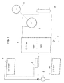
- illustrates a power plant with ORC system according to the invention for utilizing solar energy.
- Figure 2
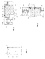
- illustrates a solar collector in front view.
- Figure 3
- A-A section of the solar collector according
fig 2 - figure 4
- B-B section of the solar collector according
fig 2 - The
solar collector 1 on thefigs. 1-4 furnishes the boiler function in an ORC system, it is able to generate superheated vapor from liquid phase of an organic working fluid directly from the solar energy. Therefor it is a heat-proof, pressure-tight and thermal insulated solar collector. - To the outlet of the
solar collector 1 offig 1 an inlet pipe of an organic steam turbine 2 (or other steam-engine) is connected. An axle of thesteam turbine 2 is mechanical connected to anelectricity generator 10. On the outlet pipe of the turbine 2 a water cooled heat exchanging condenser 3 is arranged for cooling the exhaust steam to liquid phase. On the outlet pipe of the condensed working fluid there is a storage tank 4 arranged. From the storage tank 4 a pump 5 delivers the working fluid over a oneway valve 6 to an upper (buffer)tank 7. Theupper tank 7 is connected to thesolar collector 1, only a leveling valve 8 for control the liquid level in thesolar collector 1 is interposed in this connection. The solar collector has a pressure-reducing safety valve 9 as well. - The above units of the ORC system build a closed loop for the working fluid. As working fluid there is applied a mix of heavy iso-paraffin hydrocarbons, which fluid is applicable in a temperature range between -50 °C and +350 °C. Such working fluids are disclosed among others in the
US 20060196187A1 document. - Instead of a steam-
turbine 2 other steam-engines (slow engines) can be applied, such as a reciprocating expansion-engine, or a modified scroll-compressor or worm-compressor installed as motor for converting the energy of expanding steam to rotary motion. - The solar collector 1 (
figs. 2-4 ) comprises a pipe-work 13 in a thermalisolated space 16 covered by sheet-glass 14 framed in aframework 12. Two parallel sheets of hardened sheet-glass 14 are framed in a double-walled framework 12, which framework has an air-hole 19 andspacers 21 of termo-isolating material between its inner andouter walls work 13 has a wing-plate 15 for each prong, arranged parallel to the sheet-glasses 14 and brazed to the pipes for collecting and to conduit the heat energy to the pipe-work. Thespace 16 is thermal isolated by termo-isolating material 17, 17' arranged around and at the back of the wing-plates 15, binnen theinner wall 18 of the double walled frame-work 12 and a beck-panel 26 of thesolar collector 1. In and outgoing pipe-ends are isolated by bushingseal 24 in the openings of theinner wall 18. - Both sheets of hardened
glass 14 are framed in the front opening of the 12 frame-work between the outer andinner walls seals glass 14 are welded together, between both sheets there is a closed hole of about 10 mm width. - Preferably the
solar collector 1 has a supportingframe 25 and is arranged in a fixed (facing to northern) position facing of one or more, sunshine reflecting mirrors (not depicted). - Preferably the
solar collector 1 is completed by controllable diffractive lamellas and/or diffractive cover (not depicted) for controlling the collected solar energy during the day and for preventing overdose of collected energy by very intensive sunshine. - Working of the ORC system utilizing solar energy in a power generating plant in view of
figs. 1-4 can be interpreted as follows: - The volume of the pipe-
work 13 of thesolar collector 1 is not fully filled with liquid working fluid, it has a lower part of volume for the liquid (liquid area) and a higher part of volume (vapor area) for vapor phase of the working fluid. The level of the working liquid is continuously stabilized by the leveling valve 8 which is connected to a level-sensor. The pump 5 creates a pressure of about 15 - 20 bar in theupper tank 7 and in thesolar collector 1. Collected energy of the sunshine overheats and vaporises a part of the working fluid, so that overheated steam gets to theturbine 2, where it expands converting the heat energy to mechanical energy. The exhaust steam fromturbine 2 gets in the water cooled condenser 3, where it will be converted in liquid phase. This liquid will be collected in the storage tank 4, by only 2-3 bar pressure. The low pressure (2-4 bar) section of the closed lupe of the working fluid is separated by the oneway valve 6 from the high pressure (15 - 18 bar) section of the closed lupe. Applying the upper (buffer)tank 7 provides the possibility of the periodic work instead of continuous work of the pump 5. - The above description and example have been provided for purpose of illustration and are not meant to limit the invention in any way. As will be apparent to a skilled person, the invention can be carried out in using different compounds, all without exceeding the scope of the invention.
Claims (5)
- ORC system utilizing solar energy in a power generating plant, comprising of solar collector (1), steam-engine with heat exchanging condenser (3), storage tank (4) for working fluid and pump (5) for delivery working fluid to the solar collector, characterized in that at least one heat-proof and pressure-tight solar collector (1) furnishing the boiler function of the ORC system in working has a liquid area and a vapor area in it, and said solar collector (1) is equipped with a leveling valve (8) on its inlet for ORC working fluid pumped by pump (5) from storage tank (4) to an upper tank (7) on which upper tank (7) the inlet of the leveling valve (8) is connected.
- ORC system utilizing solar energy according to claim 1, characterized in that the solar collector (1) is arranged in fixed position facing of one or more, sunshine reflecting mirrors.
- Solar collector arrangement for ORC system according to claim 1 or 2 comprising at least one solar collector (1) comprising a pipe-work (13) in a thermal isolated space (16) covered by sheet-glass framed in a framework, characterized in that two parallel sheets of hardened glass (14) are framed in a double-walled frame-work (12) which has an air-hole (19) between its inner and outer walls (18, 20).
- Solar collector arrangement according to claim 3, characterized in that the solar collector (1) is arranged in a fixed position facing of one or more, sunshine reflecting mirrors.
- Solar collector arrangement according claim 3 or 4, characterized in that the solar collector (1) is completed by controllable diffractive lamellas and/or diffractive cover.
Applications Claiming Priority (2)
| Application Number | Priority Date | Filing Date | Title |
|---|---|---|---|
| HU0600261U HU3359U (en) | 2006-11-28 | 2006-11-28 | Solar collector for power stations |
| HU20060600260U HU3312U (en) | 2006-11-28 | 2006-11-28 | Solar-based power station |
Publications (1)
| Publication Number | Publication Date |
|---|---|
| EP1927749A2 true EP1927749A2 (en) | 2008-06-04 |
Family
ID=39111310
Family Applications (1)
| Application Number | Title | Priority Date | Filing Date |
|---|---|---|---|
| EP07119259A Withdrawn EP1927749A2 (en) | 2006-11-28 | 2007-10-25 | ORC system utilizing solar energy in a power plant and solar collector arrangement |
Country Status (1)
| Country | Link |
|---|---|
| EP (1) | EP1927749A2 (en) |
Cited By (3)
| Publication number | Priority date | Publication date | Assignee | Title |
|---|---|---|---|---|
| DE102008058933A1 (en) * | 2008-11-25 | 2010-05-27 | Bartholomäus, Alexander Christian | System for supplying a heat consumer and method for operating such a system |
| WO2010111688A3 (en) * | 2009-03-26 | 2011-01-13 | Solar Storage Company | Intermediate pressure storage system for thermal storage |
| NO332743B1 (en) * | 2010-01-22 | 2013-01-02 | Francke Hans Christian | Solar panel, and systems for interconnecting multiple solar panels |
-
2007
- 2007-10-25 EP EP07119259A patent/EP1927749A2/en not_active Withdrawn
Cited By (6)
| Publication number | Priority date | Publication date | Assignee | Title |
|---|---|---|---|---|
| DE102008058933A1 (en) * | 2008-11-25 | 2010-05-27 | Bartholomäus, Alexander Christian | System for supplying a heat consumer and method for operating such a system |
| WO2010111688A3 (en) * | 2009-03-26 | 2011-01-13 | Solar Storage Company | Intermediate pressure storage system for thermal storage |
| CN102449302A (en) * | 2009-03-26 | 2012-05-09 | 太阳存储系统公司 | Intermediate pressure storage system for thermal storage |
| CN102449302B (en) * | 2009-03-26 | 2014-06-04 | 太阳存储系统公司 | Intermediate pressure storage system for thermal storage |
| US10047637B2 (en) | 2009-03-26 | 2018-08-14 | Terrajoule Corporation | Intermediate pressure storage system for thermal storage |
| NO332743B1 (en) * | 2010-01-22 | 2013-01-02 | Francke Hans Christian | Solar panel, and systems for interconnecting multiple solar panels |
Similar Documents
| Publication | Publication Date | Title |
|---|---|---|
| US5444972A (en) | Solar-gas combined cycle electrical generating system | |
| EP0997613B1 (en) | Power generator | |
| AU2010326107B2 (en) | Utilizing steam and/or hot water generated using solar energy | |
| US8881528B2 (en) | System for the generation of mechanical and/or electrical energy | |
| US20040244376A1 (en) | Systems and methods for generating electrical power from solar energy | |
| EP0457399A2 (en) | Cogeneration system with a stirling engine | |
| WO2019081916A1 (en) | Energy storage apparatus and method | |
| US20130047611A1 (en) | Solar power plant part of a solar thermal power plant and solar thermal power plant provided with solar collector surfaces for a heat transfer medium and working medium | |
| JP2011058367A (en) | Compound energy utilization system | |
| BG110419A (en) | Method and layout of a heat hydro engine for the transformation of thermal energy into mechanic | |
| Benabdellah et al. | Energy, exergy, and economic analysis of an integrated solar combined cycle power plant | |
| Tavana et al. | Optimizing building energy efficiency with a combined cooling, heating, and power (CCHP) system driven by boiler waste heat recovery | |
| Maraver et al. | Efficiency enhancement in existing biomass organic Rankine cycle plants by means of thermoelectric systems integration | |
| EP1927749A2 (en) | ORC system utilizing solar energy in a power plant and solar collector arrangement | |
| EP2765357B1 (en) | Steam power plant with an additional flexible solar system for the flexible integration of solar energy | |
| Hai et al. | Assessing and optimizing a cutting-edge renewable-driven system for green hydrogen production/utilization, highlighting techno-economic and sustainability aspects | |
| US20100089059A1 (en) | Hybrid Power Facilities | |
| KR101247772B1 (en) | generator of ship using the organic rankine cycle | |
| US20100154417A1 (en) | Hybrid Power Solar Facilities | |
| RU2440504C1 (en) | Cogeneration plant with internal combustion engine and stirling engine | |
| WO2009152496A1 (en) | Hybrid power solar facilities | |
| Mansir et al. | Comparison of three arrangements of internal combustion engine-driven energy systems boosted with PEM fuel cell towards net-zero energy systems | |
| Iaria et al. | Solar dish micro gas turbine technology for distributed power generation | |
| KR101918632B1 (en) | Plant using waste fuel and solar heat and method for controlling the same | |
| RU2681725C1 (en) | Thermal generator |
Legal Events
| Date | Code | Title | Description |
|---|---|---|---|
| PUAI | Public reference made under article 153(3) epc to a published international application that has entered the european phase |
Free format text: ORIGINAL CODE: 0009012 |
|
| AK | Designated contracting states |
Kind code of ref document: A2 Designated state(s): AT BE BG CH CY CZ DE DK EE ES FI FR GB GR HU IE IS IT LI LT LU LV MC MT NL PL PT RO SE SI SK TR |
|
| AX | Request for extension of the european patent |
Extension state: AL BA HR MK RS |
|
| STAA | Information on the status of an ep patent application or granted ep patent |
Free format text: STATUS: THE APPLICATION IS DEEMED TO BE WITHDRAWN |
|
| 18D | Application deemed to be withdrawn |
Effective date: 20100504 |