EP1927729A2 - Methods and system for recuperated cooling of integral turbine nozzle and shroud assemblies - Google Patents
Methods and system for recuperated cooling of integral turbine nozzle and shroud assemblies Download PDFInfo
- Publication number
- EP1927729A2 EP1927729A2 EP07117452A EP07117452A EP1927729A2 EP 1927729 A2 EP1927729 A2 EP 1927729A2 EP 07117452 A EP07117452 A EP 07117452A EP 07117452 A EP07117452 A EP 07117452A EP 1927729 A2 EP1927729 A2 EP 1927729A2
- Authority
- EP
- European Patent Office
- Prior art keywords
- cooling
- shroud
- gap
- turbine nozzle
- leading edge
- Prior art date
- Legal status (The legal status is an assumption and is not a legal conclusion. Google has not performed a legal analysis and makes no representation as to the accuracy of the status listed.)
- Withdrawn
Links
Images



Classifications
-
- F—MECHANICAL ENGINEERING; LIGHTING; HEATING; WEAPONS; BLASTING
- F01—MACHINES OR ENGINES IN GENERAL; ENGINE PLANTS IN GENERAL; STEAM ENGINES
- F01D—NON-POSITIVE DISPLACEMENT MACHINES OR ENGINES, e.g. STEAM TURBINES
- F01D11/00—Preventing or minimising internal leakage of working-fluid, e.g. between stages
- F01D11/08—Preventing or minimising internal leakage of working-fluid, e.g. between stages for sealing space between rotor blade tips and stator
- F01D11/14—Adjusting or regulating tip-clearance, i.e. distance between rotor-blade tips and stator casing
- F01D11/20—Actively adjusting tip-clearance
- F01D11/24—Actively adjusting tip-clearance by selectively cooling-heating stator or rotor components
-
- F—MECHANICAL ENGINEERING; LIGHTING; HEATING; WEAPONS; BLASTING
- F05—INDEXING SCHEMES RELATING TO ENGINES OR PUMPS IN VARIOUS SUBCLASSES OF CLASSES F01-F04
- F05D—INDEXING SCHEME FOR ASPECTS RELATING TO NON-POSITIVE-DISPLACEMENT MACHINES OR ENGINES, GAS-TURBINES OR JET-PROPULSION PLANTS
- F05D2240/00—Components
- F05D2240/10—Stators
- F05D2240/11—Shroud seal segments
-
- Y—GENERAL TAGGING OF NEW TECHNOLOGICAL DEVELOPMENTS; GENERAL TAGGING OF CROSS-SECTIONAL TECHNOLOGIES SPANNING OVER SEVERAL SECTIONS OF THE IPC; TECHNICAL SUBJECTS COVERED BY FORMER USPC CROSS-REFERENCE ART COLLECTIONS [XRACs] AND DIGESTS
- Y02—TECHNOLOGIES OR APPLICATIONS FOR MITIGATION OR ADAPTATION AGAINST CLIMATE CHANGE
- Y02T—CLIMATE CHANGE MITIGATION TECHNOLOGIES RELATED TO TRANSPORTATION
- Y02T50/00—Aeronautics or air transport
- Y02T50/60—Efficient propulsion technologies, e.g. for aircraft
Definitions
- This invention relates generally to gas turbine engines and, more particularly, to methods and systems for cooling integral turbine nozzle and shroud assemblies.
- one component that is subjected to high temperatures is the shroud assembly located immediately downstream of the high pressure turbine nozzle extending from the combustor.
- the shroud assembly extends circumferentially about the rotor of the high pressure turbine and thus defines a portion of the outer boundary (flow path) of the main gas stream flowing through the high pressure turbine.
- Gas turbine engine efficiency may be negatively affected by a fluctuation in turbine blade clearance measured between a radially outer surface of the turbine blade and a radially inner surface of the shroud assembly.
- turbine blade clearance is a function of a difference in radial displacement of the turbine rotor blade and the shroud assembly.
- the turbine rotor typically has a larger mass than the stationary shroud system and, thus, during turbine operation, the turbine rotor typically has a slower thermal response than the shroud assembly.
- the difference in the rotor blade radial displacement and the shroud assembly radial displacement is too great, the blade clearance is increased, which may result in reducing engine efficiency.
- a gap may be defined between a trailing edge of the high pressure turbine nozzle outer band and a leading edge of the adjacent shroud segment. Cooling air, including, without limitation, nozzle leakage and/or purge flow, enters the gap and flows into the main gas stream channeled through the high pressure turbine. More specifically, because known nozzle outer band trailing edges and shroud leading edges have a simple 90° corner, the gap opens directly into the main gas stream.
- a circumferential gas pressure variation may be created downstream from the vane trailing edge. This circumferential gas pressure variation may cause localized hot gas ingestion into the gap between the outer band and the shroud segment. As a result, cooling air flowing through the gap may not effectively cool the downstream shroud segement.
- a method for cooling a shroud segment of a gas turbine engine includes providing a turbine shroud assembly including a shroud segment having an inner surface and a leading edge that is substantially perpendicular to the inner surface, and coupling a turbine nozzle to the turbine shroud segment such that a gap is defined between an aft edge of an outer band of the turbine nozzle and the leading edge.
- the method also includes directing cooling air into the gap, and directing the cooling air in the gap through at least one cooling hole extending between the leading edge and the inner surface.
- a turbine nozzle and shroud assembly for a gas turbine engine.
- the turbine nozzle and shroud assembly include a shroud segment including a leading edge and an inner surface that is substantially perpendicular to the leading edge, and a turbine nozzle including an outer band having an aft edge.
- the turbine nozzle is upstream from the shroud segment and coupled with the shroud segment such that a gap is defined between the aft edge and the leading edge.
- the shroud segment includes at least one cooling hole extending between the leading edge and the inner surface. The at least one cooling hole is configured to direct cooling air in the gap toward the hot gas flow path.
- a cooling system for a gas turbine engine in another aspect, includes a shroud segment having a leading edge and an inner surface that is substantially perpendicular to the leading edge, and a turbine nozzle including an outer band having an aft edge.
- the turbine nozzle is positioned upstream of the shroud segment and is coupled to the shroud segment such that a gap is defined between the aft edge and the leading edge.
- the cooling system includes at least one cooling hole formed between the leading edge and the inner surface. The cooling system is configured to direct cooling air in the gap toward a hot gas flow path defined within the gas turbine engine.
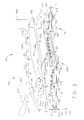
- Figure 1 is a side view of an exemplary shroud assembly schematically illustrating high pressure cooling air flow through the shroud assembly.
- Figure 2 is a side view of an alternative shroud assembly schematically illustrating high pressure cooling air flow through the shroud assembly.
- Figure 3 is a schematic view of a portion of an exemplary turbine nozzle and shroud assembly.
- Figure 4 is a schematic view of an alternative embodiment of a portion of a turbine nozzle and shroud assembly.
- the present invention provides a turbine shroud cooling system for film cooling a shroud segment.
- the turbine shroud cooling system facilitates forming a barrier between the hot gas flow path flowing through the high pressure turbine and cooling air flowing through a gap defined between the turbine nozzle and the shroud segment. More specifically, an extended lip at a trailing edge of the outer band facilitates forming the barrier between the hot gas flow path and the gap defined between an outer band of the turbine nozzle and the shroud segment. Further, the extended lip facilitates pressurizing the gap to facilitate preventing or limiting hot gas injection into the gap. In one embodiment, the extended lip forms an axial aft facing film cooling slot in parallel with a rounded corner portion of the shroud leading edge to facilitate film cooling the downstream shroud segment.
- cooling system or assembly of the present invention can also be suitable to facilitate cooling other turbine engine components, such as, but not limited to, the nozzle and/or vane sections.
- a turbine engine cooling assembly 108 includes a shroud assembly, generally indicated as 110, for a high pressure turbine section 112 and a low pressure turbine section 114 of a gas turbine engine. It should be apparent to those skilled in the art and guided by the teachings herein provided that turbine engine cooling assembly 108 may be suitable to facilitate cooling other sections of the gas turbine engine, such as, but not limited to, a nozzle section and/or a vane section.
- Shroud assembly 110 includes turbine engine cooling components in the form of shroud segments 130.
- Each shroud segment 130 includes a forward mounting hook 132 at a circumferential leading edge 133 of shroud segment 130.
- Shroud segment 130 also includes a midsection mounting hook 134 and an aft mounting hook 136 adjacent to a circumferential trailing edge 137 of shroud segment 130.
- a plurality of shroud segments 130 are arranged circumferentially in a generally known fashion to form an annular segmented shroud.
- Shroud segments 130 define an annular clearance between high pressure turbine blades (not shown) and a radially inner surface 138 of a high pressure turbine section of shroud segments 130, and between low pressure turbine blades (not shown) and a radially inner surface 140 of a low pressure turbine section of shroud segment 130.
- a plurality of segmented shroud supports 144 interconnect shroud segments 130. Each shroud support 144 circumferentially spans and supports adjacent shroud segments 130. In alternative embodiments, shroud supports 144 are modified to support any suitable number of shroud segments 130 less than or greater than two shroud segments 130.
- shroud assembly 110 includes twenty-six (26) shroud segments 130 and thirteen (13) shroud supports 144, although any suitable number of shroud segments 130 and/or shroud supports 144 may be utilized in alternative embodiments.
- Each shroud support 144 includes a forward section 146, a midsection 148 and an aft section 150 that form respective forwardly projecting hangers 152, 154 and 156.
- Mounting hooks 132, 134 and 136 are received by cooperating hangers 152, 154 and 156, respectively, in tongue-in-groove, or hook-in-hanger, interconnections such that shroud support 144 supports respective shroud segments 130.
- Shroud assembly 110 includes an annular shroud ring structure 158 that supports shroud supports 144.
- shroud ring structure 158 is a one-piece, continuous annular shroud ring structure.
- a radial position of each shroud support 144, as well as of each shroud segment 130, is closely controlled by only two annular position control rings 162 and 164 formed on shroud ring structure 158.
- shroud ring structure 158 includes only two position control rings 162 and 164.
- a midsection position control ring 162 includes an axially forwardly projecting hanger 166 that receives and/or cooperates with a rearwardly projecting mounting hook 167 formed by support structure midsection 148 in a first circumferential tongue-in-groove or hook-in-hanger interconnection.
- An aft position control ring 164 includes an axially forwardly projecting hanger 168 that receives and/or cooperates with a rearwardly projecting mounting hook 169 of support structure aft section 150 in second circumferential tongue-in-groove or hook-in-hanger interconnection.
- hangers 166 and/or 168 are in direct axial alignment, i.e., aligned generally in the same radial plane, with respective hanger 154 and hanger 156 to facilitate maximizing the radial support and/or radial position control provided to shroud support 144 and, thus, corresponding shroud segments 130.
- This alignment orientation facilitates increasing the rigidity of the entire shroud support assembly.
- hanger 166 and/or hanger 168 are in an offset axial alignment, i.e., not aligned generally in the same radial plane, with respective hanger 154 and hanger 156.
- shroud ring structure 158 is bolted to the combustor case (not shown) at an aft end of shroud ring structure 158.
- Shroud ring structure 158 is cantilevered away from leading edge 133 at the combustor case interface.
- midsection position control ring 162 is positioned several inches away from the combustor aft flange (not shown), and is thereby divorced from any non-uniform circumferential variations in radial deflection in the combustor case.
- high pressure cooling air 170 is extracted from a compressor (not shown) positioned upstream of shroud assembly 110.
- a first portion 171 of high pressure cooling air 170 extracted from the compressor facilitates cooling high pressure turbine section 112.
- a second portion 172 of high pressure cooling air 170 extracted from the compressor facilitates cooling low pressure turbine section 114.
- directional arrows corresponding to first portion 171 and second portion 172 illustrate at least a portion of a flow path of first portion 171 of high pressure cooling air 170 through a high pressure turbine section active convection cooling zone 173 and second portion 172 of high pressure cooling air 170 through a low pressure turbine section active convection cooling zone 186 (described below), respectively.
- first portion 171 of high pressure cooling air 170 is metered into a first or high pressure turbine section active convection cooling zone 173. More specifically, first portion 171 of high pressure cooling air 170 is metered through at least one high pressure turbine section (HPTS) feed hole 174 defined in shroud support 144. First portion 171 of high pressure cooling air 170 impinges against a pan-shaped HPTS impingement baffle 175 positioned within high pressure turbine section active convection cooling zone 173. Baffle 175 is coupled to shroud support 144 and thus at least partially defines an upper HPTS cavity or plenum 176.
- HPTS high pressure turbine section
- First portion 171 of high pressure cooling air 170 is then metered through a plurality of perforations 177 formed in impingement baffle 175 as cooling air into a lower HPTS cavity or plenum 178 defined in shroud segment 130, wherein the cooling air impinges against a backside 179 of shroud segment 130.
- a portion, such as spent impingement cooling air 180, of high pressure cooling air exits plenum 178 through a plurality of forwardly directed cooling openings 181 defined at, or near, shroud segment leading edge 133 configured to facilitate purging a gap 182 defined between high pressure turbine nozzle outer band 183 and leading edge 133.
- a portion 184 of high pressure cooling air is metered through a plurality of rearwardly directed cooling openings 185 defined in shroud segment 130 to facilitate film cooling inner surface 138 and/or 140.
- Spent impingement cooling air 180 of high pressure cooling air exiting cooling openings 181 facilitates preventing or limiting hot gas injection or recirculation into shroud assembly 110 at leading edge 133.
- Second portion 172 of high pressure cooling air 170 extracted from the compressor facilitates cooling low pressure turbine section 114.
- second portion 172 of high pressure cooling air 170 is metered into a second or low pressure turbine section active convection cooling zone 186. More specifically, second portion 172 of high pressure cooling air 170 is metered through at least one low pressure turbine feed hole 187 defined in shroud support 144.
- Second portion 172 of high pressure cooling air 170 impinges against a pan-shaped low pressure turbine section (LPTS) impingement baffle 188 positioned within low pressure turbine section active convection cooling zone 186.
- Baffle 188 is coupled to shroud support 144, and thus at least partially defines an upper LPTS cavity or plenum 189.
- Second portion 172 of high pressure cooling air 170 is then metered through perforations 190 defined in impingement baffle 188 and into a lower LPTS cavity or plenum 191 wherein high pressure cooling air impinges against a backside 192 of shroud segment 130.
- Cooling air 193 exits plenum 191 through a plurality of rearwardly directed cooling openings 194 defined through shroud segment 130, to facilitate film cooling radially inner surface 140 of trailing edge 137 of shroud segment 130 downstream.
- high pressure cooling air 170 is initially directed into a duct 204 defined at least partially between high pressure turbine nozzle outer band 183 and the portion of shroud ring structure 158 forming midsection position control ring 162.
- High pressure cooling air 170 is separated within duct 204 into first portion 171, and into second portion 172, as high pressure cooling air 170 is directed through duct 204.
- First portion 171 of high pressure cooling air 170 is metered through HPTS feed holes 174 into active convection cooling zone 173 and into plenum 178 to facilitate impingement cooling in high pressure turbine section 112.
- Spent impingement cooling air 180 exits shroud segment 130 through shroud segment leading edge cooling openings 181 to facilitate purging gap 182 defined between high pressure turbine nozzle outer band 183 and shroud segment 130, and/or through cooling openings 185 defined at a trailing end 205 of high pressure turbine section 112 to facilitate film cooling inner surface 138 and/or 140 of shroud segment 130.
- Second portion 172 of high pressure cooling air 170 is directed into second active convection cooling zone 186 that is defined at least partially between shroud support 144 and shroud segment 130, and between midsection position control ring 162 and aft position control ring 164. Second portion 172 of high pressure cooling air 170 facilitates cooling low pressure turbine section 114. In one embodiment, second portion 172 of high pressure cooling air 170 is metered through a plurality of low pressure turbine feed holes 187 defined in shroud support 144.
- second portion 172 of high pressure cooling air 170 is metered directly into active convection cooling zone 186 to facilitate shroud segment impingement cooling in low pressure turbine section 114, such that cooling air bypasses a third region 210 defining an inactive convection cooling zone 211 between shroud support 144 and shroud ring structure 158, and between midsection position control ring 162 and aft position control ring 164.
- Spent impingement cooling air exits shroud segment 130 through cooling openings 194 defined at or near trailing edge 137 of shroud segment 130.
- high pressure turbine section active convection cooling zone 173 and/or low pressure turbine section active convection cooling zone 186 are directly and actively cooled.
- Low pressure turbine section inactive convection cooling zone 211 is inactive, i.e., no high pressure cooling air flows through inactive convection cooling zone 211.
- a thermal response within inactive convection cooling zone 211 to environmental conditions created during transient engine operation is reduced and/or retarded.
- transient displacement of midsection position control ring 162 and/or aft position control ring 164 is also reduced and/or retarded.
- high pressure cooling air 170 is directed into duct 204 defined at least partially between high pressure turbine nozzle outer band 183 and shroud ring structure 158 forming midsection position control ring 162.
- High pressure cooling air 170 is separated into first portion 171 and second portion 172.
- First portion 171 of high pressure cooling air 170 is metered through HPTS feed hole(s) 174 into high pressure turbine section active convection cooling zone 173 at least partially defining plenum 176 and plenum 178 to facilitate shroud segment impingement cooling in high pressure turbine section 112.
- Spent impingement cooling air 180 exits shroud segment 130 through shroud segment leading edge cooling openings 181 to facilitate purging gap 182 between high pressure turbine nozzle outer band 183 and shroud segment 130 and/or through cooling openings 185 defined at trailing end 205 of high pressure turbine section 112 to facilitate film cooling inner surface 138 and/or 140.
- Second portion 172 of high pressure cooling air 170 is directed into low pressure turbine section active convection cooling zone 186 defined at least partially between shroud support 144 and shroud segment 130, and between midsection position control ring 162 and aft position control ring 164 to facilitate cooling low pressure turbine section 114.
- second portion 172 of high pressure cooling air 170 is metered through a plurality of low pressure turbine feed holes 187 defined through shroud support 144.
- Second portion 172 of high pressure cooling air 170 is metered directly into low pressure turbine section active convection cooling zone 186 at least partially defining plenum 189 and plenum 191 to facilitate shroud segment impingement cooling in low pressure turbine section 114.
- Spent impingement cooling air 193 exits shroud segment 130 through cooling openings 194 defined at or near trailing edge 137 of shroud segment 130.
- the shroud cooling assembly as shown in Figures 1 and 2 directs high pressure cooling air directly into high pressure turbine section active convection cooling zone 173 and/or low pressure turbine section active convection cooling zone 186 through respective feed hole(s) 174 and feed hole(s) 187.
- the high pressure cooling air flow paths shown in Figures 1 and 2 facilitate reducing and/or retarding the transient thermal response and/or displacement of the shroud segment during transient engine operation.
- the slower response further facilitates improved blade tip clearance and turbine engine efficiency.
- FIG 3 illustrates a portion of an exemplary turbine nozzle and shroud assembly 300 for use in a gas turbine engine.
- Shroud assembly 300 is similar to shroud assembly 110, and as such, components illustrated in Figure 3 that are identical to components illustrated in Figures 1 and 2 are identified in Figure 3 using the same reference number used in Figures 1 and 2 .
- Gap 182 is defined at an interface between outer band 183 of an upstream turbine nozzle 112 and an immediately downstream and adjacent shroud assembly 110 that includes a shroud segment 302.
- turbine nozzle 112 is coupled to shroud segment 302 to form turbine nozzle and shroud assembly 300.
- a shroud segment leading edge 304 defines a forward face 306 of shroud segment 302.
- a radially inner surface 308 of shroud segment 302 extends substantially perpendicularly to forward face 306.
- a rounded or arcuate corner portion 310 extends between forward face 306 and inner surface 308 and partially defines gap 182.
- Outer band 183 has a trailing edge 314 that defines an aft face 316 of outer band 183.
- gap 182 is generally defined between aft face 316 and forward face 306.
- Gap 182 enables cooling air to flow radially inwardly towards a combustion gas or hot gas flow path 320.
- Hot gas flow path 320 flows generally parallel to a central axis 322 defined by the gas turbine engine.
- the cooling air may include leakage air 324 directed from duct 204, shown in Figure 1 , and/or shroud leading edge cooling air 326 discharged from active convection cooling zone 173, shown in Figure 1 .
- shroud segment leading edge 304 includes at least one forwardly directed cooling opening 360 that extends substantially perpendicularly therethrough.
- at least one discrete convection cooling hole 362 extends between forward face 306 and inner surface 308.
- convection cooling hole 362 extends obliquely through forward face 306 to inner surface 308 at a location that is radially inward from cooling opening 360.
- cooling opening 360 meters a flow of shroud leading edge cooling air 326 into gap 182.
- Cooling air 326 is discharged from cooling opening 360 into gap 182, wherein the air 326 mixes with leakage air 324 discharged from duct 204, shown in Figure 1 .
- a portion of the mixed cooling air 364 is channeled through the at least one discrete convection cooling hole 362 to inner surface 308 to facilitate forming a recuperated film cooling layer 366 across inner surface 308.
- the remaining mixed cooling air 364 is discharged from gap 182 to facilitate film cooling of corner portion 310.
- Film cooling layer 366 facilitates forming a cooling barrier between hot gas flow path 320 and shroud segment 302.
- cooling air 364 discharged from hole 362 provides energy to cooling layer 366 such that film cooling layer 366 is facilitated to be maintained in proximity to surface 308 for a longer distance across surface 308 prior to separating from surface 308.
- an operating temparture of shroud segment 302 is reduced such that a useful life of the turbine engine and/or shroud segment is facilitated to be increased.
- Figure 4 illustrates an alternative embodiment of turbine nozzle and shroud assembly 300.
- the alternative embodiment illustrated in Figure 4 is substantially similar to the embodiment shown in Figure 3 .
- components illustrated in Figure 4 that are identical to components illustrated in Figure 3 are identified in Figure 4 using the same reference number used in Figure 3 .
- Gap 182 is defined at an interface between an outer band 400 of an upstream turbine nozzle 402 and an immediately downstream and adjacent shroud assembly 110 that includes a shroud segment 302.
- turbine nozzle 402 is coupled to shroud segment 302 to form turbine nozzle and shroud assembly 300 for a gas turbine engine.
- a lip 404 is formed on an aft face 406 of turbine nozzle 402. More specifically, in the exemplary embodiment, lip 404 is positioned radially inwardly from gap 182 and corner portion 310, and extends downstream, generally parallel to central axis 322, from aft face 406.
- At least one discharge opening 408 is defined in aft face 406.
- discharge opening 408 extends obliquely through aft face 406 and is radially outward from lip 404.
- Discharge opening 408 meters the flow of spent turbine nozzle cooling air 410 against lip 404.
- spent turbine nozzle cooling air 410 is metered towards lip 404 from a turbine nozzle active convection cooling zone 412 that is at least partially defined by outer band 400.
- spent turbine nozzle cooling air 410 is discharged from discharge opening 408 in a metered flow directed towards lip 404.
- Lip 404 re-directs cooling air 410 towards corner portion 310 and inner surface 308.
- cooling air 364 is channeled through convection cooling hole 362 towards inner surface 308. Cooling air 364 and cooling air 410 mix adjacent inner surface 308 to facilitate forming a recuperated film cooling layer 414 across inner surface 308. Further, because lip 404 extends downstream from aft face 406, downstream from gap 182, lip 404 enables gap 182 to be pressurized to facilitate film cooling layer 414 being formed.
- Film cooling layer 414 facilitates forming a cooling barrier between hot gas flow path 320 and shroud segment 302, such that undesirable hot gas injection into gap 182 due to nozzle trailing edge wake effect is facilitated to be reduced. Moreover, film cooling layer 414 facilitates reducing an operating temperature of shroud segment 302, such that a useful life of the turbine engine and/or shroud assembly 110 is facilitated to be increased.
- cooling opening 360 extends through shroud segment leading edge 304 to meter a flow of shroud leading edge cooling air 326 into gap 182. Moreover, in the exemplary embodiments, cooling opening 360 is radially outward from convection cooling hole 362 such that shroud leading edge cooling air 326 discharged into gap 182 from cooling opening 360 is mixed with leakage air 324 directed from duct 204, shown in Figure 1 . A portion of the resulting mixed cooling air 364 is channeled through convection cooling hole 362 towards inner surface 308 to facilitate forming a recuperated film cooling layer 366 across inner surface 308.
- lip 404 is positioned radially inward from at least one discharge opening 408, such that spent turbine nozzle cooling air 410 discharged from opening 408, is re-directed by lip 404 across corner portion 310 and towards inner surface 308.
- Mixed cooling air 364 discharged from discrete convection cooling hole 362, and cooling air 410 discharged from opening 408, are mixed adjacent surface 308 to facilitate forming a recuperated film cooling layer 414 across inner surface 308.
- Film cooling layers 366 and 414 facilitate forming a cooling barrier between hot gas flow path 320 shroud segment 302, such that undesirable hot gas injection into gap 182 due to nozzle trailing edge wake effect is facilitated to be reduced.
- film cooling layers 366 and 414 facilitate reducing an operating temperature of shroud segment 302. As such, film cooling layers 366 and 414 facilitate increasing a useful life of the turbine engine and/or shroud assembly 110.
- the above-described methods and systems facilitate film cooling a shroud segment.
- the methods and systems facilitate forming a barrier between the hot gas flow path flowing through the high pressure turbine and cooling air flowing through and exiting a gap defined between the turbine nozzle and the shroud segment. More specifically, cooling air flowing through the gap is directed through an opening extending through a leading edge of the shroud segment to facilitate forming a cooling layer on the shroud segment inner surface.
- spent turbine nozzle cooling air exiting the turbine nozzle outer band is directed to impinge against a lip extending from the trailing edge of the turbine nozzle.
- the lip is positioned radially inward from the gap and extends downstream from the gap to direct the cooling air towards a rounded corner portion formed on the leading edge of the shroud segment.
- the corner facilitates forming or developing a film cooling layer at, near, or adjacent to, the inner surface of the shroud segment downstream of the gap.
- the film layer is formed from a combination of cooling air directed by the lip and corner portion and cooling air discharged from the opening that extends through the shroud segment leading edge.
- the extended lip serves as a barrier between the hot gas flow path and the cooling air flowing through and exiting the gap defined between the outer band and the shroud segment.
- the extended lip facilitates pressurizing the cooling air within the gap to substantially prevent or limit hot gas injection into the gap due to nozzle trailing edge wake effect as may be seen in conventional cooling systems or assemblies.
- the film cooling layer facilitates reducing a temperature of the shroud segment, such that the film cooling layer facilitates increasing a life-span of the turbine engine and/or increasing an efficiency of the turbine engine.
- a method for cooling a shroud segment of a gas turbine engine includes providing a turbine shroud assembly including a shroud segment having an inner surface and a leading edge that is substantially perpendicular to the inner surface, and coupling a turbine nozzle to the turbine shroud segment such that a gap is defined between an aft edge of an outer band of the turbine nozzle and the leading edge.
- the method also includes directing cooling air into the gap, and directing the cooling air in the gap through at least one opening formed between the leading edge and the inner surface.
Landscapes
- Engineering & Computer Science (AREA)
- Mechanical Engineering (AREA)
- General Engineering & Computer Science (AREA)
- Turbine Rotor Nozzle Sealing (AREA)
Abstract
Description
- This invention relates generally to gas turbine engines and, more particularly, to methods and systems for cooling integral turbine nozzle and shroud assemblies.
- One known approach to increase the efficiency of gas turbine engines requires raising the turbine operating temperature. However, as operating temperatures are increased, the thermal limits of certain engine components may be exceeded, resulting in reduced service life and/or material failure. Moreover, the increased thermal expansion and contraction of components may adversely affect component clearances and/or component interfitting relationships. Consequently, conventional cooling systems have been incorporated into gas turbine engines to facilitate cooling such components to avoid potentially damaging consequences when exposed to elevated operating temperatures.
- It is known to extract, from the main airstream, air from the compressor for cooling purposes. To facilitate maintaining engine operating efficiency, the volume of cooling air extracted is typically limited to a small percentage of the total main airstream. As such, this requires that the cooling air be utilized with the utmost efficiency in order to facilitate maintaining the temperatures of components within safe limits.
- For example, one component that is subjected to high temperatures is the shroud assembly located immediately downstream of the high pressure turbine nozzle extending from the combustor. The shroud assembly extends circumferentially about the rotor of the high pressure turbine and thus defines a portion of the outer boundary (flow path) of the main gas stream flowing through the high pressure turbine. Gas turbine engine efficiency may be negatively affected by a fluctuation in turbine blade clearance measured between a radially outer surface of the turbine blade and a radially inner surface of the shroud assembly. During transient engine operation, turbine blade clearance is a function of a difference in radial displacement of the turbine rotor blade and the shroud assembly. The turbine rotor typically has a larger mass than the stationary shroud system and, thus, during turbine operation, the turbine rotor typically has a slower thermal response than the shroud assembly. When the difference in the rotor blade radial displacement and the shroud assembly radial displacement is too great, the blade clearance is increased, which may result in reducing engine efficiency.
- Moreoever, during engine operation, a gap may be defined between a trailing edge of the high pressure turbine nozzle outer band and a leading edge of the adjacent shroud segment. Cooling air, including, without limitation, nozzle leakage and/or purge flow, enters the gap and flows into the main gas stream channeled through the high pressure turbine. More specifically, because known nozzle outer band trailing edges and shroud leading edges have a simple 90° corner, the gap opens directly into the main gas stream. During engine operation, as the main gas stream flows through the nozzle vanes, a circumferential gas pressure variation may be created downstream from the vane trailing edge. This circumferential gas pressure variation may cause localized hot gas ingestion into the gap between the outer band and the shroud segment. As a result, cooling air flowing through the gap may not effectively cool the downstream shroud segement.
- In one aspect, a method for cooling a shroud segment of a gas turbine engine is provided. The method includes providing a turbine shroud assembly including a shroud segment having an inner surface and a leading edge that is substantially perpendicular to the inner surface, and coupling a turbine nozzle to the turbine shroud segment such that a gap is defined between an aft edge of an outer band of the turbine nozzle and the leading edge. The method also includes directing cooling air into the gap, and directing the cooling air in the gap through at least one cooling hole extending between the leading edge and the inner surface.
- In a further aspect, a turbine nozzle and shroud assembly for a gas turbine engine is provided. The turbine nozzle and shroud assembly include a shroud segment including a leading edge and an inner surface that is substantially perpendicular to the leading edge, and a turbine nozzle including an outer band having an aft edge. The turbine nozzle is upstream from the shroud segment and coupled with the shroud segment such that a gap is defined between the aft edge and the leading edge. The shroud segment includes at least one cooling hole extending between the leading edge and the inner surface. The at least one cooling hole is configured to direct cooling air in the gap toward the hot gas flow path.
- In another aspect, a cooling system for a gas turbine engine is provided. The gas turbine engine includes a shroud segment having a leading edge and an inner surface that is substantially perpendicular to the leading edge, and a turbine nozzle including an outer band having an aft edge. The turbine nozzle is positioned upstream of the shroud segment and is coupled to the shroud segment such that a gap is defined between the aft edge and the leading edge. The cooling system includes at least one cooling hole formed between the leading edge and the inner surface. The cooling system is configured to direct cooling air in the gap toward a hot gas flow path defined within the gas turbine engine.
- Embodiments of the present invention will now be described by way of example only, with reference to the accompanying drawings, in which:
-
Figure 1 is a side view of an exemplary shroud assembly schematically illustrating high pressure cooling air flow through the shroud assembly. -
Figure 2 is a side view of an alternative shroud assembly schematically illustrating high pressure cooling air flow through the shroud assembly. -
Figure 3 is a schematic view of a portion of an exemplary turbine nozzle and shroud assembly. -
Figure 4 is a schematic view of an alternative embodiment of a portion of a turbine nozzle and shroud assembly. - The present invention provides a turbine shroud cooling system for film cooling a shroud segment. The turbine shroud cooling system facilitates forming a barrier between the hot gas flow path flowing through the high pressure turbine and cooling air flowing through a gap defined between the turbine nozzle and the shroud segment. More specifically, an extended lip at a trailing edge of the outer band facilitates forming the barrier between the hot gas flow path and the gap defined between an outer band of the turbine nozzle and the shroud segment. Further, the extended lip facilitates pressurizing the gap to facilitate preventing or limiting hot gas injection into the gap. In one embodiment, the extended lip forms an axial aft facing film cooling slot in parallel with a rounded corner portion of the shroud leading edge to facilitate film cooling the downstream shroud segment.
- Although the present invention is described below in reference to its application in connection with cooling a shroud assembly of an aircraft gas turbine, it should be apparent to those skilled in the art and guided by the teachings herein provided that with appropriate modification, the cooling system or assembly of the present invention can also be suitable to facilitate cooling other turbine engine components, such as, but not limited to, the nozzle and/or vane sections.
-
Figure 1 is a side view of an exemplary shroud assembly schematically illustrating high pressure cooling air flow through the shroud assembly.Figure 2 is a side view of an alternative shroud assembly schematically illustrating high pressure cooling air flow through the shroud assembly. To facilitate controlling shroud assembly thermal response and/or shroud assembly displacement during transient engine operation, in the exemplary embodiment, a turbineengine cooling assembly 108 includes a shroud assembly, generally indicated as 110, for a highpressure turbine section 112 and a lowpressure turbine section 114 of a gas turbine engine. It should be apparent to those skilled in the art and guided by the teachings herein provided that turbineengine cooling assembly 108 may be suitable to facilitate cooling other sections of the gas turbine engine, such as, but not limited to, a nozzle section and/or a vane section. - Shroud
assembly 110 includes turbine engine cooling components in the form ofshroud segments 130. Eachshroud segment 130 includes aforward mounting hook 132 at a circumferential leading edge 133 ofshroud segment 130. Shroudsegment 130 also includes amidsection mounting hook 134 and anaft mounting hook 136 adjacent to a circumferentialtrailing edge 137 ofshroud segment 130. - A plurality of
shroud segments 130 are arranged circumferentially in a generally known fashion to form an annular segmented shroud.Shroud segments 130 define an annular clearance between high pressure turbine blades (not shown) and a radiallyinner surface 138 of a high pressure turbine section ofshroud segments 130, and between low pressure turbine blades (not shown) and a radiallyinner surface 140 of a low pressure turbine section ofshroud segment 130. A plurality of segmented shroud supports 144interconnect shroud segments 130. Each shroud support 144 circumferentially spans and supportsadjacent shroud segments 130. In alternative embodiments,shroud supports 144 are modified to support any suitable number ofshroud segments 130 less than or greater than twoshroud segments 130. In the exemplary embodiment,shroud assembly 110 includes twenty-six (26)shroud segments 130 and thirteen (13) shroud supports 144, although any suitable number ofshroud segments 130 and/orshroud supports 144 may be utilized in alternative embodiments. - Each
shroud support 144 includes aforward section 146, amidsection 148 and anaft section 150 that form respective forwardly projectinghangers Mounting hooks hangers shroud support 144 supportsrespective shroud segments 130. - Shroud
assembly 110 includes an annularshroud ring structure 158 that supports shroud supports 144. In one embodiment,shroud ring structure 158 is a one-piece, continuous annular shroud ring structure. A radial position of eachshroud support 144, as well as of eachshroud segment 130, is closely controlled by only two annular position control rings 162 and 164 formed onshroud ring structure 158. In contrast to conventional shroud ring structures, to facilitate reducing or limiting a weight ofshroud assembly 110,shroud ring structure 158 includes only two position control rings 162 and 164. A midsectionposition control ring 162 includes an axially forwardly projectinghanger 166 that receives and/or cooperates with a rearwardly projecting mountinghook 167 formed bysupport structure midsection 148 in a first circumferential tongue-in-groove or hook-in-hanger interconnection. An aftposition control ring 164 includes an axially forwardly projectinghanger 168 that receives and/or cooperates with a rearwardly projecting mountinghook 169 of support structure aftsection 150 in second circumferential tongue-in-groove or hook-in-hanger interconnection. - In the exemplary embodiment,
hangers 166 and/or 168 are in direct axial alignment, i.e., aligned generally in the same radial plane, withrespective hanger 154 andhanger 156 to facilitate maximizing the radial support and/or radial position control provided toshroud support 144 and, thus,corresponding shroud segments 130. This alignment orientation facilitates increasing the rigidity of the entire shroud support assembly. In an alternative embodiment, shown inFigure 2 ,hanger 166 and/orhanger 168 are in an offset axial alignment, i.e., not aligned generally in the same radial plane, withrespective hanger 154 andhanger 156. In the exemplary embodiment,shroud ring structure 158 is bolted to the combustor case (not shown) at an aft end ofshroud ring structure 158.Shroud ring structure 158 is cantilevered away from leading edge 133 at the combustor case interface. As such, midsectionposition control ring 162 is positioned several inches away from the combustor aft flange (not shown), and is thereby divorced from any non-uniform circumferential variations in radial deflection in the combustor case. - In the exemplary embodiment, high
pressure cooling air 170 is extracted from a compressor (not shown) positioned upstream ofshroud assembly 110. Afirst portion 171 of highpressure cooling air 170 extracted from the compressor facilitates cooling highpressure turbine section 112. Asecond portion 172 of highpressure cooling air 170 extracted from the compressor facilitates cooling lowpressure turbine section 114. Referring further toFigure 1 , directional arrows corresponding tofirst portion 171 andsecond portion 172 illustrate at least a portion of a flow path offirst portion 171 of highpressure cooling air 170 through a high pressure turbine section activeconvection cooling zone 173 andsecond portion 172 of highpressure cooling air 170 through a low pressure turbine section active convection cooling zone 186 (described below), respectively. - In this embodiment,
first portion 171 of highpressure cooling air 170 is metered into a first or high pressure turbine section activeconvection cooling zone 173. More specifically,first portion 171 of highpressure cooling air 170 is metered through at least one high pressure turbine section (HPTS)feed hole 174 defined inshroud support 144.First portion 171 of highpressure cooling air 170 impinges against a pan-shaped HPTS impingement baffle 175 positioned within high pressure turbine section activeconvection cooling zone 173.Baffle 175 is coupled toshroud support 144 and thus at least partially defines an upper HPTS cavity orplenum 176.First portion 171 of highpressure cooling air 170 is then metered through a plurality ofperforations 177 formed inimpingement baffle 175 as cooling air into a lower HPTS cavity orplenum 178 defined inshroud segment 130, wherein the cooling air impinges against abackside 179 ofshroud segment 130. A portion, such as spentimpingement cooling air 180, of high pressure cooling air exits plenum 178 through a plurality of forwardly directed coolingopenings 181 defined at, or near, shroud segment leading edge 133 configured to facilitate purging agap 182 defined between high pressure turbine nozzleouter band 183 and leading edge 133. Aportion 184 of high pressure cooling air is metered through a plurality of rearwardly directed coolingopenings 185 defined inshroud segment 130 to facilitate film coolinginner surface 138 and/or 140. Spentimpingement cooling air 180 of high pressure cooling air exiting coolingopenings 181 facilitates preventing or limiting hot gas injection or recirculation intoshroud assembly 110 at leading edge 133. -
Second portion 172 of highpressure cooling air 170 extracted from the compressor facilitates cooling lowpressure turbine section 114. In this embodiment,second portion 172 of highpressure cooling air 170 is metered into a second or low pressure turbine section activeconvection cooling zone 186. More specifically,second portion 172 of highpressure cooling air 170 is metered through at least one low pressureturbine feed hole 187 defined inshroud support 144.Second portion 172 of highpressure cooling air 170 impinges against a pan-shaped low pressure turbine section (LPTS)impingement baffle 188 positioned within low pressure turbine section activeconvection cooling zone 186.Baffle 188 is coupled toshroud support 144, and thus at least partially defines an upper LPTS cavity orplenum 189.Second portion 172 of highpressure cooling air 170 is then metered throughperforations 190 defined inimpingement baffle 188 and into a lower LPTS cavity orplenum 191 wherein high pressure cooling air impinges against abackside 192 ofshroud segment 130.Cooling air 193 exits plenum 191 through a plurality of rearwardly directed coolingopenings 194 defined throughshroud segment 130, to facilitate film cooling radiallyinner surface 140 of trailingedge 137 ofshroud segment 130 downstream. - As shown in
Figure 1 , highpressure cooling air 170 is initially directed into aduct 204 defined at least partially between high pressure turbine nozzleouter band 183 and the portion ofshroud ring structure 158 forming midsectionposition control ring 162. Highpressure cooling air 170 is separated withinduct 204 intofirst portion 171, and intosecond portion 172, as highpressure cooling air 170 is directed throughduct 204.First portion 171 of highpressure cooling air 170 is metered through HPTS feed holes 174 into activeconvection cooling zone 173 and intoplenum 178 to facilitate impingement cooling in highpressure turbine section 112. Spentimpingement cooling air 180 exitsshroud segment 130 through shroud segment leadingedge cooling openings 181 to facilitatepurging gap 182 defined between high pressure turbine nozzleouter band 183 andshroud segment 130, and/or through coolingopenings 185 defined at a trailingend 205 of highpressure turbine section 112 to facilitate film coolinginner surface 138 and/or 140 ofshroud segment 130. -
Second portion 172 of highpressure cooling air 170 is directed into second activeconvection cooling zone 186 that is defined at least partially betweenshroud support 144 andshroud segment 130, and between midsectionposition control ring 162 and aftposition control ring 164.Second portion 172 of highpressure cooling air 170 facilitates cooling lowpressure turbine section 114. In one embodiment,second portion 172 of highpressure cooling air 170 is metered through a plurality of low pressure turbine feed holes 187 defined inshroud support 144. More specifically,second portion 172 of highpressure cooling air 170 is metered directly into activeconvection cooling zone 186 to facilitate shroud segment impingement cooling in lowpressure turbine section 114, such that cooling air bypasses athird region 210 defining an inactiveconvection cooling zone 211 betweenshroud support 144 andshroud ring structure 158, and between midsectionposition control ring 162 and aftposition control ring 164. Spent impingement cooling air exitsshroud segment 130 through coolingopenings 194 defined at or near trailingedge 137 ofshroud segment 130. - In the flow path illustrated in
Figure 1 , high pressure turbine section activeconvection cooling zone 173 and/or low pressure turbine section activeconvection cooling zone 186 are directly and actively cooled. Low pressure turbine section inactiveconvection cooling zone 211 is inactive, i.e., no high pressure cooling air flows through inactiveconvection cooling zone 211. Thus, a thermal response within inactiveconvection cooling zone 211 to environmental conditions created during transient engine operation is reduced and/or retarded. As a result, transient displacement of midsectionposition control ring 162 and/or aftposition control ring 164 is also reduced and/or retarded. - As shown in
Figure 2 , highpressure cooling air 170 is directed intoduct 204 defined at least partially between high pressure turbine nozzleouter band 183 andshroud ring structure 158 forming midsectionposition control ring 162. Highpressure cooling air 170 is separated intofirst portion 171 andsecond portion 172.First portion 171 of highpressure cooling air 170 is metered through HPTS feed hole(s) 174 into high pressure turbine section activeconvection cooling zone 173 at least partially definingplenum 176 andplenum 178 to facilitate shroud segment impingement cooling in highpressure turbine section 112. Spentimpingement cooling air 180 exitsshroud segment 130 through shroud segment leadingedge cooling openings 181 to facilitatepurging gap 182 between high pressure turbine nozzleouter band 183 andshroud segment 130 and/or through coolingopenings 185 defined at trailingend 205 of highpressure turbine section 112 to facilitate film coolinginner surface 138 and/or 140. -
Second portion 172 of highpressure cooling air 170 is directed into low pressure turbine section activeconvection cooling zone 186 defined at least partially betweenshroud support 144 andshroud segment 130, and between midsectionposition control ring 162 and aftposition control ring 164 to facilitate cooling lowpressure turbine section 114. In one embodiment,second portion 172 of highpressure cooling air 170 is metered through a plurality of low pressure turbine feed holes 187 defined throughshroud support 144.Second portion 172 of highpressure cooling air 170 is metered directly into low pressure turbine section activeconvection cooling zone 186 at least partially definingplenum 189 andplenum 191 to facilitate shroud segment impingement cooling in lowpressure turbine section 114. Spentimpingement cooling air 193 exitsshroud segment 130 through coolingopenings 194 defined at or near trailingedge 137 ofshroud segment 130. - The shroud cooling assembly as shown in
Figures 1 and2 directs high pressure cooling air directly into high pressure turbine section activeconvection cooling zone 173 and/or low pressure turbine section activeconvection cooling zone 186 through respective feed hole(s) 174 and feed hole(s) 187. - In the shroud cooling assembly as shown in
Figures 1 and2 , high pressure cooling air is not metered or directed through low pressure turbine section inactiveconvection cooling zone 211. As a result, the components defining low pressure turbine section inactiveconvection cooling zone 211 respond relatively slower to thermal conditions and/or environments during transient engine operation than the components defining an active convection cooling zone within conventional shroud cooling assemblies. This slower response to thermal conditions and/or environments facilitates relatively slower transient displacement of midsectionposition control ring 162 and/or aftposition control ring 164. - Thus, by bypassing the low pressure turbine section shroud ring structure, the high pressure cooling air flow paths shown in
Figures 1 and2 facilitate reducing and/or retarding the transient thermal response and/or displacement of the shroud segment during transient engine operation. The slower response further facilitates improved blade tip clearance and turbine engine efficiency. -
Figure 3 illustrates a portion of an exemplary turbine nozzle andshroud assembly 300 for use in a gas turbine engine.Shroud assembly 300 is similar toshroud assembly 110, and as such, components illustrated inFigure 3 that are identical to components illustrated inFigures 1 and2 are identified inFigure 3 using the same reference number used inFigures 1 and2 .Gap 182 is defined at an interface betweenouter band 183 of anupstream turbine nozzle 112 and an immediately downstream andadjacent shroud assembly 110 that includes ashroud segment 302. In the exemplary embodiment,turbine nozzle 112 is coupled toshroud segment 302 to form turbine nozzle andshroud assembly 300. - A shroud
segment leading edge 304 defines aforward face 306 ofshroud segment 302. In the exemplary embodiment, a radiallyinner surface 308 ofshroud segment 302 extends substantially perpendicularly toforward face 306. Moreover, in the exemplary embodiment, a rounded orarcuate corner portion 310 extends betweenforward face 306 andinner surface 308 and partially definesgap 182. -
Outer band 183 has a trailingedge 314 that defines anaft face 316 ofouter band 183. Whenturbine nozzle 112 is coupled toshroud segment 302,gap 182 is generally defined betweenaft face 316 andforward face 306.Gap 182 enables cooling air to flow radially inwardly towards a combustion gas or hotgas flow path 320. Hotgas flow path 320 flows generally parallel to acentral axis 322 defined by the gas turbine engine. The cooling air may includeleakage air 324 directed fromduct 204, shown inFigure 1 , and/or shroud leadingedge cooling air 326 discharged from activeconvection cooling zone 173, shown inFigure 1 . - In the exemplary embodiment, shroud
segment leading edge 304 includes at least one forwardly directed coolingopening 360 that extends substantially perpendicularly therethrough. Moreover, in the exemplary embodiment, at least one discreteconvection cooling hole 362 extends betweenforward face 306 andinner surface 308. Specifically, in the exemplary embodiment,convection cooling hole 362 extends obliquely throughforward face 306 toinner surface 308 at a location that is radially inward from coolingopening 360. - During operation, cooling opening 360 meters a flow of shroud leading
edge cooling air 326 intogap 182.Cooling air 326 is discharged from cooling opening 360 intogap 182, wherein theair 326 mixes withleakage air 324 discharged fromduct 204, shown inFigure 1 . A portion of themixed cooling air 364 is channeled through the at least one discreteconvection cooling hole 362 toinner surface 308 to facilitate forming a recuperatedfilm cooling layer 366 acrossinner surface 308. The remainingmixed cooling air 364 is discharged fromgap 182 to facilitate film cooling ofcorner portion 310.Film cooling layer 366 facilitates forming a cooling barrier between hotgas flow path 320 andshroud segment 302. Moreover, coolingair 364 discharged fromhole 362 provides energy to coolinglayer 366 such thatfilm cooling layer 366 is facilitated to be maintained in proximity to surface 308 for a longer distance acrosssurface 308 prior to separating fromsurface 308. As a result, an operating temparture ofshroud segment 302 is reduced such that a useful life of the turbine engine and/or shroud segment is facilitated to be increased. -
Figure 4 illustrates an alternative embodiment of turbine nozzle andshroud assembly 300. The alternative embodiment illustrated inFigure 4 is substantially similar to the embodiment shown inFigure 3 . As such, components illustrated inFigure 4 that are identical to components illustrated inFigure 3 are identified inFigure 4 using the same reference number used inFigure 3 .Gap 182 is defined at an interface between anouter band 400 of anupstream turbine nozzle 402 and an immediately downstream andadjacent shroud assembly 110 that includes ashroud segment 302. In the exemplary embodiment,turbine nozzle 402 is coupled toshroud segment 302 to form turbine nozzle andshroud assembly 300 for a gas turbine engine. In the exemplary embodiment, alip 404 is formed on anaft face 406 ofturbine nozzle 402. More specifically, in the exemplary embodiment,lip 404 is positioned radially inwardly fromgap 182 andcorner portion 310, and extends downstream, generally parallel tocentral axis 322, fromaft face 406. - In the exemplary embodiment, at least one
discharge opening 408 is defined inaft face 406. Specifically, discharge opening 408 extends obliquely throughaft face 406 and is radially outward fromlip 404. Discharge opening 408 meters the flow of spent turbinenozzle cooling air 410 againstlip 404. Specifically, spent turbinenozzle cooling air 410 is metered towardslip 404 from a turbine nozzle activeconvection cooling zone 412 that is at least partially defined byouter band 400. - During operation, spent turbine
nozzle cooling air 410 is discharged from discharge opening 408 in a metered flow directed towardslip 404.Lip 404re-directs cooling air 410 towardscorner portion 310 andinner surface 308. Moreover, coolingair 364 is channeled throughconvection cooling hole 362 towardsinner surface 308.Cooling air 364 and coolingair 410 mix adjacentinner surface 308 to facilitate forming a recuperatedfilm cooling layer 414 acrossinner surface 308. Further, becauselip 404 extends downstream fromaft face 406, downstream fromgap 182,lip 404 enablesgap 182 to be pressurized to facilitatefilm cooling layer 414 being formed.Film cooling layer 414 facilitates forming a cooling barrier between hotgas flow path 320 andshroud segment 302, such that undesirable hot gas injection intogap 182 due to nozzle trailing edge wake effect is facilitated to be reduced. Moreover,film cooling layer 414 facilitates reducing an operating temperature ofshroud segment 302, such that a useful life of the turbine engine and/orshroud assembly 110 is facilitated to be increased. - Referring to
Figures 3 and4 , in the exemplary embodiments, cooling opening 360 extends through shroudsegment leading edge 304 to meter a flow of shroud leadingedge cooling air 326 intogap 182. Moreover, in the exemplary embodiments, cooling opening 360 is radially outward fromconvection cooling hole 362 such that shroud leadingedge cooling air 326 discharged intogap 182 from cooling opening 360 is mixed withleakage air 324 directed fromduct 204, shown inFigure 1 . A portion of the resultingmixed cooling air 364 is channeled throughconvection cooling hole 362 towardsinner surface 308 to facilitate forming a recuperatedfilm cooling layer 366 acrossinner surface 308. In one embodiment,lip 404 is positioned radially inward from at least onedischarge opening 408, such that spent turbinenozzle cooling air 410 discharged from opening 408, is re-directed bylip 404 acrosscorner portion 310 and towardsinner surface 308.Mixed cooling air 364 discharged from discreteconvection cooling hole 362, and coolingair 410 discharged from opening 408, are mixedadjacent surface 308 to facilitate forming a recuperatedfilm cooling layer 414 acrossinner surface 308. Film cooling layers 366 and 414 facilitate forming a cooling barrier between hotgas flow path 320shroud segment 302, such that undesirable hot gas injection intogap 182 due to nozzle trailing edge wake effect is facilitated to be reduced. Moreover,film cooling layers shroud segment 302. As such,film cooling layers shroud assembly 110. - The above-described methods and systems facilitate film cooling a shroud segment. The methods and systems facilitate forming a barrier between the hot gas flow path flowing through the high pressure turbine and cooling air flowing through and exiting a gap defined between the turbine nozzle and the shroud segment. More specifically, cooling air flowing through the gap is directed through an opening extending through a leading edge of the shroud segment to facilitate forming a cooling layer on the shroud segment inner surface. In an alternative embodiment, spent turbine nozzle cooling air exiting the turbine nozzle outer band is directed to impinge against a lip extending from the trailing edge of the turbine nozzle. The lip is positioned radially inward from the gap and extends downstream from the gap to direct the cooling air towards a rounded corner portion formed on the leading edge of the shroud segment. The corner facilitates forming or developing a film cooling layer at, near, or adjacent to, the inner surface of the shroud segment downstream of the gap. Specifically, the film layer is formed from a combination of cooling air directed by the lip and corner portion and cooling air discharged from the opening that extends through the shroud segment leading edge. In one embodiment, the extended lip serves as a barrier between the hot gas flow path and the cooling air flowing through and exiting the gap defined between the outer band and the shroud segment. Further, the extended lip facilitates pressurizing the cooling air within the gap to substantially prevent or limit hot gas injection into the gap due to nozzle trailing edge wake effect as may be seen in conventional cooling systems or assemblies. Moreover, the film cooling layer facilitates reducing a temperature of the shroud segment, such that the film cooling layer facilitates increasing a life-span of the turbine engine and/or increasing an efficiency of the turbine engine.
- In one embodiment, a method for cooling a shroud segment of a gas turbine engine is provided. The method includes providing a turbine shroud assembly including a shroud segment having an inner surface and a leading edge that is substantially perpendicular to the inner surface, and coupling a turbine nozzle to the turbine shroud segment such that a gap is defined between an aft edge of an outer band of the turbine nozzle and the leading edge. The method also includes directing cooling air into the gap, and directing the cooling air in the gap through at least one opening formed between the leading edge and the inner surface.
- Exemplary embodiments of methods and systems for film cooling a shroud segment are described above in detail. The method and system are not limited to the specific embodiments described herein, but rather, steps of the method and/or components of the system may be utilized independently and separately from other steps and/or components described herein. Further, the described method steps and/or system components can also be defined in, or used in combination with, other methods and/or systems, and are not limited to practice with only the method and system as described herein.
- While the invention has been described in terms of various specific embodiments, those skilled in the art will recognize that the invention can be practiced with modification within the spirit and scope of the claims.
Claims (10)
- A turbine nozzle and shroud assembly (110) for a gas turbine engine (108), said turbine nozzle and shroud assembly comprising:a shroud segment comprising a leading edge (133) and an inner surface that is substantially perpendicular to said leading edge; anda turbine nozzle comprising an outer band (183) comprising an aft edge (150), said turbine nozzle is upstream from said shroud segment and is coupled with said shroud segment such that a gap (182) is defined between said aft edge and said leading edge, said shroud segment comprises at least one cooling hole formed between said leading edge and said inner surface, said at least one cooling hole (181) is configured to direct cooling air in said gap toward the hot gas flow path (320).
- A turbine nozzle and shroud assembly (110) in accordance with Claim 1 wherein said at least one cooling hole (181) is further configured to direct cooling air in the gap (182) towards said inner surface to facilitate forming a recuperated film cooling layer across said inner surface.
- A turbine nozzle and shroud assembly (110) in accordance with Claim 1 further comprising at least one forwardly directed cooling opening (185) defined in said leading edge (133), said at least one forwardly directed cooling opening is radially outward from said at least one cooling hole formed between said leading edge and said inner surface and is configured to meter cooling air into said gap.
- A turbine nozzle and shroud assembly (110) in accordance with Claim 1 further comprising a duct (204) at least partially defined by said turbine nozzle (112) and said turbine shroud segment (130), said duct configured to direct cooling air into said gap (182).
- A turbine nozzle and shroud assembly (110) in accordance with Claim 1 further comprising:a lip (404) formed on said aft edge, said lip extends downstream from said gap; andat least one discharge opening (408) extending through said aft edge, said at least one discharge opening configured to meter spent turbine nozzle cooling air (180) into said gap, such that said lip directs the spent turbine nozzle cooling air from said gap towards said shroud segment (130) to facilitate cooling said shroud segment.
- A turbine nozzle and shroud assembly (110) in accordance with any one of the preceding Claims further comprising a rounded corner portion (310) extending between said leading edge (133) and said inner surface, said rounded corner portion configured to direct the spent turbine nozzle cooling air (180) towards said inner surface to facilitate forming a film cooling layer against said inner surface.
- A turbine nozzle and shroud assembly (110) in accordance with Claim 1 wherein said gap (182) is pressurized to facilitate minimizing a turbine nozzle wake effect within said gap.
- A cooling system (108) for a gas turbine engine that includes a shroud segment (130) having a leading edge (133) and an inner surface that is substantially perpendicular to the leading edge, and a turbine nozzle (112) that is upstream from the shroud segment and that includes an outer band (183) having an aft edge, said cooling system comprising at least one cooling hole (185) formed between the leading edge and the inner surface, said cooling system is configured to direct cooling air from a gap defined between the aft edge and the leading edge towards a hot gas flow path (320) defined within the gas turbine engine.
- A cooling system (108) in accordance with Claim 8 further configured to direct cooling air from the gap (182) through said at least one cooling hole extending between the leading edge and the inner surface to facilitate forming a recuperated film cooling layer across the inner surface of the shroud segment (130).
- A cooling system (108) in accordance with Claim 8 further comprising at least one forwardly directed cooling opening (181) defined in the leading edge (133), said at least one forwardly directed cooling opening is radially outward from said at least one cooling hole extending between the leading edge and the inner surface, said at least one forwardly directed cooling opening is configured to meter cooling air into the gap (182).
Applications Claiming Priority (1)
| Application Number | Priority Date | Filing Date | Title |
|---|---|---|---|
| US11/565,176 US7665953B2 (en) | 2006-11-30 | 2006-11-30 | Methods and system for recuperated cooling of integral turbine nozzle and shroud assemblies |
Publications (2)
| Publication Number | Publication Date |
|---|---|
| EP1927729A2 true EP1927729A2 (en) | 2008-06-04 |
| EP1927729A3 EP1927729A3 (en) | 2012-11-21 |
Family
ID=38577666
Family Applications (1)
| Application Number | Title | Priority Date | Filing Date |
|---|---|---|---|
| EP07117452A Withdrawn EP1927729A3 (en) | 2006-11-30 | 2007-09-28 | Methods and system for recuperated cooling of integral turbine nozzle and shroud assemblies |
Country Status (4)
| Country | Link |
|---|---|
| US (1) | US7665953B2 (en) |
| EP (1) | EP1927729A3 (en) |
| JP (1) | JP5230159B2 (en) |
| CA (1) | CA2603636A1 (en) |
Cited By (2)
| Publication number | Priority date | Publication date | Assignee | Title |
|---|---|---|---|---|
| EP2902590A1 (en) * | 2013-05-14 | 2015-08-05 | Rolls-Royce plc | A shroud arrangement for a gas turbine engine |
| FR3039200A1 (en) * | 2015-07-22 | 2017-01-27 | Turbomeca | TURBINE RING COOLING |
Families Citing this family (9)
| Publication number | Priority date | Publication date | Assignee | Title |
|---|---|---|---|---|
| US8147192B2 (en) * | 2008-09-19 | 2012-04-03 | General Electric Company | Dual stage turbine shroud |
| US9103225B2 (en) * | 2012-06-04 | 2015-08-11 | United Technologies Corporation | Blade outer air seal with cored passages |
| US9657642B2 (en) | 2014-03-27 | 2017-05-23 | Honeywell International Inc. | Turbine sections of gas turbine engines with dual use of cooling air |
| JP6312929B2 (en) | 2014-09-08 | 2018-04-18 | シーメンス エナジー インコーポレイテッド | In the platform, a cooled turbine vane platform having a front, a middle string and a rear cooling chamber |
| US9957827B2 (en) * | 2014-10-24 | 2018-05-01 | United Technologies Corporation | Conformal seal |
| US9587502B2 (en) * | 2015-03-06 | 2017-03-07 | United Technologies Corporation | Sliding compliant seal |
| WO2016148694A1 (en) | 2015-03-17 | 2016-09-22 | Siemens Energy, Inc. | Shrouded turbine airfoil with leakage flow conditioner |
| US11242764B2 (en) * | 2018-05-17 | 2022-02-08 | Raytheon Technologies Corporation | Seal assembly with baffle for gas turbine engine |
| CN114576014B (en) * | 2022-03-09 | 2024-05-14 | 广东信稳能控技术研究有限公司 | Aircraft thermal cycle power system |
Family Cites Families (23)
| Publication number | Priority date | Publication date | Assignee | Title |
|---|---|---|---|---|
| US3864056A (en) * | 1973-07-27 | 1975-02-04 | Westinghouse Electric Corp | Cooled turbine blade ring assembly |
| US3990807A (en) * | 1974-12-23 | 1976-11-09 | United Technologies Corporation | Thermal response shroud for rotating body |
| JPS52109017A (en) * | 1976-03-08 | 1977-09-12 | Hitachi Ltd | Cooling and void seal device for moving vane nose part |
| US4526226A (en) * | 1981-08-31 | 1985-07-02 | General Electric Company | Multiple-impingement cooled structure |
| US4949545A (en) * | 1988-12-12 | 1990-08-21 | Sundstrand Corporation | Turbine wheel and nozzle cooling |
| US5217348A (en) * | 1992-09-24 | 1993-06-08 | United Technologies Corporation | Turbine vane assembly with integrally cast cooling fluid nozzle |
| US5511945A (en) * | 1994-10-31 | 1996-04-30 | Solar Turbines Incorporated | Turbine motor and blade interface cooling system |
| US5641267A (en) * | 1995-06-06 | 1997-06-24 | General Electric Company | Controlled leakage shroud panel |
| US6139257A (en) * | 1998-03-23 | 2000-10-31 | General Electric Company | Shroud cooling assembly for gas turbine engine |
| US6126389A (en) * | 1998-09-02 | 2000-10-03 | General Electric Co. | Impingement cooling for the shroud of a gas turbine |
| DE19919654A1 (en) * | 1999-04-29 | 2000-11-02 | Abb Alstom Power Ch Ag | Heat shield for a gas turbine |
| GB2354290B (en) * | 1999-09-18 | 2004-02-25 | Rolls Royce Plc | A cooling air flow control device for a gas turbine engine |
| US6340285B1 (en) * | 2000-06-08 | 2002-01-22 | General Electric Company | End rail cooling for combined high and low pressure turbine shroud |
| US6354795B1 (en) * | 2000-07-27 | 2002-03-12 | General Electric Company | Shroud cooling segment and assembly |
| US6398488B1 (en) * | 2000-09-13 | 2002-06-04 | General Electric Company | Interstage seal cooling |
| US6431832B1 (en) * | 2000-10-12 | 2002-08-13 | Solar Turbines Incorporated | Gas turbine engine airfoils with improved cooling |
| US6431820B1 (en) * | 2001-02-28 | 2002-08-13 | General Electric Company | Methods and apparatus for cooling gas turbine engine blade tips |
| US6779597B2 (en) * | 2002-01-16 | 2004-08-24 | General Electric Company | Multiple impingement cooled structure |
| US7033138B2 (en) * | 2002-09-06 | 2006-04-25 | Mitsubishi Heavy Industries, Ltd. | Ring segment of gas turbine |
| US6984100B2 (en) * | 2003-06-30 | 2006-01-10 | General Electric Company | Component and turbine assembly with film cooling |
| FR2857406B1 (en) * | 2003-07-10 | 2005-09-30 | Snecma Moteurs | COOLING THE TURBINE RINGS |
| US7147432B2 (en) * | 2003-11-24 | 2006-12-12 | General Electric Company | Turbine shroud asymmetrical cooling elements |
| US7306424B2 (en) * | 2004-12-29 | 2007-12-11 | United Technologies Corporation | Blade outer seal with micro axial flow cooling system |
-
2006
- 2006-11-30 US US11/565,176 patent/US7665953B2/en not_active Expired - Fee Related
-
2007
- 2007-09-20 CA CA002603636A patent/CA2603636A1/en not_active Abandoned
- 2007-09-28 JP JP2007254386A patent/JP5230159B2/en not_active Expired - Fee Related
- 2007-09-28 EP EP07117452A patent/EP1927729A3/en not_active Withdrawn
Cited By (3)
| Publication number | Priority date | Publication date | Assignee | Title |
|---|---|---|---|---|
| EP2902590A1 (en) * | 2013-05-14 | 2015-08-05 | Rolls-Royce plc | A shroud arrangement for a gas turbine engine |
| US9920647B2 (en) | 2013-05-14 | 2018-03-20 | Rolls-Royce Plc | Dual source cooling air shroud arrangement for a gas turbine engine |
| FR3039200A1 (en) * | 2015-07-22 | 2017-01-27 | Turbomeca | TURBINE RING COOLING |
Also Published As
| Publication number | Publication date |
|---|---|
| US20080131259A1 (en) | 2008-06-05 |
| US7665953B2 (en) | 2010-02-23 |
| JP5230159B2 (en) | 2013-07-10 |
| JP2008138662A (en) | 2008-06-19 |
| EP1927729A3 (en) | 2012-11-21 |
| CA2603636A1 (en) | 2008-05-30 |
Similar Documents
| Publication | Publication Date | Title |
|---|---|---|
| EP1930550B1 (en) | Systems for cooling integral turbine nozzle and shroud assemblies | |
| US7604453B2 (en) | Methods and system for recuperated circumferential cooling of integral turbine nozzle and shroud assemblies | |
| CA2601686C (en) | Methods and system for cooling integral turbine shroud assemblies | |
| CA2603312C (en) | Method and system to facilitate cooling turbine engines | |
| EP1927725B1 (en) | System to facilitate preferentially distributed recuperated film cooling of turbine shroud assembly | |
| EP1927729A2 (en) | Methods and system for recuperated cooling of integral turbine nozzle and shroud assemblies | |
| US11293304B2 (en) | Gas turbine engines including channel-cooled hooks for retaining a part relative to an engine casing structure | |
| CA2602311C (en) | Method and system to facilitate enhanced local cooling of turbine engines | |
| US7690885B2 (en) | Methods and system for shielding cooling air to facilitate cooling integral turbine nozzle and shroud assemblies | |
| US10422244B2 (en) | System for cooling a turbine shroud | |
| JP2006200530A (en) | Method and apparatus for maintaining rotor assembly tip clearance | |
| US11215073B2 (en) | Stator vane for a turbine of a turbomachine |
Legal Events
| Date | Code | Title | Description |
|---|---|---|---|
| PUAI | Public reference made under article 153(3) epc to a published international application that has entered the european phase |
Free format text: ORIGINAL CODE: 0009012 |
|
| AK | Designated contracting states |
Kind code of ref document: A2 Designated state(s): AT BE BG CH CY CZ DE DK EE ES FI FR GB GR HU IE IS IT LI LT LU LV MC MT NL PL PT RO SE SI SK TR |
|
| AX | Request for extension of the european patent |
Extension state: AL BA HR MK RS |
|
| PUAL | Search report despatched |
Free format text: ORIGINAL CODE: 0009013 |
|
| AK | Designated contracting states |
Kind code of ref document: A3 Designated state(s): AT BE BG CH CY CZ DE DK EE ES FI FR GB GR HU IE IS IT LI LT LU LV MC MT NL PL PT RO SE SI SK TR |
|
| AX | Request for extension of the european patent |
Extension state: AL BA HR MK RS |
|
| RIC1 | Information provided on ipc code assigned before grant |
Ipc: F01D 9/04 20060101AFI20121017BHEP |
|
| 17P | Request for examination filed |
Effective date: 20130521 |
|
| AKX | Designation fees paid |
Designated state(s): DE FR GB |
|
| STAA | Information on the status of an ep patent application or granted ep patent |
Free format text: STATUS: THE APPLICATION IS DEEMED TO BE WITHDRAWN |
|
| 18D | Application deemed to be withdrawn |
Effective date: 20160401 |