EP1927438A1 - Battery pack lockout arrangement for cordless power tools - Google Patents
Battery pack lockout arrangement for cordless power tools Download PDFInfo
- Publication number
- EP1927438A1 EP1927438A1 EP20070121412 EP07121412A EP1927438A1 EP 1927438 A1 EP1927438 A1 EP 1927438A1 EP 20070121412 EP20070121412 EP 20070121412 EP 07121412 A EP07121412 A EP 07121412A EP 1927438 A1 EP1927438 A1 EP 1927438A1
- Authority
- EP
- European Patent Office
- Prior art keywords
- power tool
- housing
- battery pack
- motor
- adapter
- Prior art date
- Legal status (The legal status is an assumption and is not a legal conclusion. Google has not performed a legal analysis and makes no representation as to the accuracy of the status listed.)
- Withdrawn
Links
- 238000010586 diagram Methods 0.000 description 3
- 230000003213 activating effect Effects 0.000 description 1
- 239000003990 capacitor Substances 0.000 description 1
Images

Classifications
-
- B—PERFORMING OPERATIONS; TRANSPORTING
- B25—HAND TOOLS; PORTABLE POWER-DRIVEN TOOLS; MANIPULATORS
- B25F—COMBINATION OR MULTI-PURPOSE TOOLS NOT OTHERWISE PROVIDED FOR; DETAILS OR COMPONENTS OF PORTABLE POWER-DRIVEN TOOLS NOT PARTICULARLY RELATED TO THE OPERATIONS PERFORMED AND NOT OTHERWISE PROVIDED FOR
- B25F5/00—Details or components of portable power-driven tools not particularly related to the operations performed and not otherwise provided for
Definitions
- This specification relates to cordless power tools and more specifically to a lockout arrangement for locking out certain power tool battery packs from certain power tools.
- a cordless power tool such as a drill 100
- a drill 100 typically has a housing 101, a motor M for driving a cutting tool, such as drill bit DB, and a power tool battery pack 10 electrically connected to motor M.
- Drill 100 may have a variable speed feature allowing the user to select the rotational speed of motor M.
- variable speed feature is integrated into trigger assembly TA, allowing the user to adjust the desired speed by pulling trigger assembly TA a certain distance.
- a typical power tool battery pack 10 has a housing 13, cells 11 disposed in the housing 13 and connected between first and second terminals A, B, and a thermistor 12 disposed in the housing 13 and connected between first and third terminals A, C. Such power tool battery pack 10 can be connected to drill 100 via terminals A, B.
- trigger assembly TA has a first switch S1, a second switch S2 and a potentiometer R1. Accordingly, when the operator closes the trigger assembly, first switch S1 closes, thereby powering up integrated circuit IC1.
- Integrated circuit IC1 is a device such as a 555 timer, micro controller, or other device capable of controlling the voltage or current or power control to motor M.
- potentiometer R1 provides a voltage signal to integrated circuit IC1 relative to trigger position. As the position of potentiometer R1 varies, the voltage presented to integrated circuit IC1 varies.
- Integrated circuit IC1 responds by activating FET Q1 with on/off pulses allowing current to flow from terminal A through switch S1 through motor M through FET Q1 (when FET Q1 is directed to be on by integrated circuit IC1). By directing FET Q1 on and off with a variable duty cycle, motor speed can be controlled. As previously stated, as the trigger assembly TA is fully engaged, FET Q1 is bypassed by second switch S2 allowing full connection to the power tool battery pack 10 for maximum power capability.
- a cordless power tool system comprising a power tool including a tool housing, a motor disposed in the tool housing, and a variable speed circuit for controlling the speed of the motor, and a power tool battery pack electrically connectable to the power tool, the power tool battery pack including a pack housing, cells disposed within the pack housing, and an electric/electronic component disposed within the pack housing and connectable to the variable speed circuit, wherein at least one of the variable speed circuit and the power tool is disabled if the variable speed circuit fails to detect the electric/electronic component.
- a cordless power tool such a drill 100
- a drill 100 preferably has a housing 101, a motor M for driving a cutting tool, such as drill bit DB, and a power tool battery pack 10 electrically connected to motor M.
- Drill 100 may have a variable speed feature allowing the user to select the rotational speed of motor M.
- such variable speed feature is integrated into trigger assembly TA, allowing the user to adjust the desired speed by pulling trigger assembly TA a certain distance.
- Power tool battery pack 10 preferably has a housing 13, cells 11 disposed in the housing 13 and connected between first and second terminals A, B, and a thermistor 12 disposed in the housing 13 and connected between first and third terminals A, C. Such power tool battery pack 10 can be connected to drill 100 via terminals A, B.
- Trigger assembly TA preferably has a first switch S1, a second switch S2 and a potentiometer R1. Accordingly, when the operator closes the trigger assembly, first switch S1 closes, thereby powering up integrated circuit IC1.
- Integrated circuit IC1 is a device such as a 555 timer, micro controller, or other device capable of controlling the voltage or current or power control to motor M.
- potentiometer R1 provides a voltage signal to integrated circuit IC1 relative to trigger position. As the position of potentiometer R1 varies, the voltage presented to integrated circuit IC1 varies.
- Integrated circuit IC1 is preferably connected to thermistor 12 via third terminal C. If integrated circuit IC1 does not detect thermistor 12, it will not turn on FET Q1, effectively disabling cordless drill 100. Alternatively, if integrated IC1 does not detect thermistor 12, it can just turn on FET Q1 full-time, effectively disabling the variable speed feature and the operator's ability to vary the speed of motor M. Disabling the variable speed feature may also be accomplished by never turning on FET Q1 such that the motor will only run full speed via closure of second switch S2. Alternately FET Q1 could be turned off and on in such a way to create an undesirable, counterintuitive, or difficult to control behavior from the motor speed control.
- thermistor 12 may replaced by other electric and/or electronic components, such as resistors, capacitors, inductors, transistors, integrated circuits, etc., which can be recognized by integrated circuit IC1.
- FIG. 4 A second embodiment of the present invention is shown in FIG. 4 , where like numerals refer to like parts. All the teachings of the first embodiment discussed above are incorporated herein by reference. The only difference between the first and second embodiments is that an adapter 20 is disposed on battery pack 10 and/or cordless drill 100. Persons skilled in the art are referred to US Patent No. 6,525,511 , which is fully incorporated herein by reference, for further information on adapter 20.
- Adapter 20 may interface one type of power tool battery pack with a cordless drill 100 that accepts a different type of power tool battery pack.
- adapter 20 may interface a tower-style power tool battery pack with a cordless drill 100 that accepts only slide-style power tool battery packs, and/or a tower-style power tool battery pack having a first terminal configuration with a cordless drill 100 that accepts only tower-style power tool battery packs having a second terminal configuration, where the cordless drill 100 would not accept the power tool battery pack having the first terminal configuration.
- Adapter 20 may also interface a power tool battery pack 10' that does not have a thermistor 12 with a cordless drill 100 that requires the presence of thermistor 12 in order to activate cordless drill 100 and/or the variable speed circuit. Such result can be accomplished as follows. Adapter 20 may be electrically connected to power tool battery pack 10 via first and second terminals A, B. Adapter 20 may in turn have third and fourth terminals A', B' that electrically connect to cordless drill 100, in the same manner the first and second (power) terminals A,B would have been connected to cordless drill 100.
- adapter 20 may have a fifth terminal C', and a thermistor 12 connected to such terminal C'.
- Terminal C' would preferably be connected to cordless drill 100 so that the presence of thermistor 12 could be detected by integrated circuit IC1.
- the adapter preferably acts as a pass-through for battery terminals A and B to connect the battery and terminal to the power tool motor.
- Adapter 20 may also have a pass-through terminal for a thermistor in battery pack 10.
- the adapter 20 may not pass through the thermistor signal by not connecting to the thermistor terminal in battery pack 10 or terminating such line within the adapter 20. Rather the connection to the integrated circuit IC1 could be made by an electronic/electrical element in the adapter 20 itself (taking the place of the thermistor in the battery pack 10) thereby impersonating the thermistor lock-out feature of the circuit.
- the electronic/electrical element could be a thermistor, resistor, or other element that would signal the variable speed circuit to operate in a normally desirable manner.
Landscapes
- Engineering & Computer Science (AREA)
- Mechanical Engineering (AREA)
- Secondary Cells (AREA)
- Charge And Discharge Circuits For Batteries Or The Like (AREA)
Abstract
Description
- This specification relates to cordless power tools and more specifically to a lockout arrangement for locking out certain power tool battery packs from certain power tools.
- Referring to
FIGS. 1-2 , a cordless power tool, such adrill 100, typically has ahousing 101, a motor M for driving a cutting tool, such as drill bit DB, and a powertool battery pack 10 electrically connected to motor M. Drill 100 may have a variable speed feature allowing the user to select the rotational speed of motor M. Typically such variable speed feature is integrated into trigger assembly TA, allowing the user to adjust the desired speed by pulling trigger assembly TA a certain distance. - A typical power
tool battery pack 10 has a housing 13, cells 11 disposed in the housing 13 and connected between first and second terminals A, B, and athermistor 12 disposed in the housing 13 and connected between first and third terminals A, C. Such powertool battery pack 10 can be connected to drill 100 via terminals A, B. - Typically trigger assembly TA has a first switch S1, a second switch S2 and a potentiometer R1. Accordingly, when the operator closes the trigger assembly, first switch S1 closes, thereby powering up integrated circuit IC1. Integrated circuit IC1 is a device such as a 555 timer, micro controller, or other device capable of controlling the voltage or current or power control to motor M. After first switch S1 is closed, potentiometer R1 provides a voltage signal to integrated circuit IC1 relative to trigger position. As the position of potentiometer R1 varies, the voltage presented to integrated circuit IC1 varies. Integrated circuit IC1 responds by activating FET Q1 with on/off pulses allowing current to flow from terminal A through switch S1 through motor M through FET Q1 (when FET Q1 is directed to be on by integrated circuit IC1). By directing FET Q1 on and off with a variable duty cycle, motor speed can be controlled. As previously stated, as the trigger assembly TA is fully engaged, FET Q1 is bypassed by second switch S2 allowing full connection to the power
tool battery pack 10 for maximum power capability. - It is preferable to ensure that certain power tools can only be used with certain battery packs, and to lock out undesirable battery packs, which may not meet quality requirements, etc.
- A cordless power tool system comprising a power tool including a tool housing, a motor disposed in the tool housing, and a variable speed circuit for controlling the speed of the motor, and a power tool battery pack electrically connectable to the power tool, the power tool battery pack including a pack housing, cells disposed within the pack housing, and an electric/electronic component disposed within the pack housing and connectable to the variable speed circuit, wherein at least one of the variable speed circuit and the power tool is disabled if the variable speed circuit fails to detect the electric/electronic component.
- The accompanying drawings illustrate preferred embodiments according to the practical application of the principles thereof, and in which:
-
FIG. 1 illustrates a typical cordless power tool. -
FIG. 2 is a schematic diagram of the prior art power tool/power tool battery pack system. -
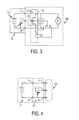
FIG. 3 is a schematic diagram of the power tool/power tool battery pack system according to the invention. -
FIG. 4 is a partial schematic diagram of the power tool/adapter/power tool battery pack system according to the invention. - The present invention will now be described more fully hereinafter. This invention may, however, be embodied in many different forms and should not be construed as limited to the embodiments set forth herein; rather, these embodiments are provided so that this disclosure will be thorough and complete, and will fully convey the scope of the invention to those skilled in the art.
- Referring first to
FIGS. 1 and3 , where like numerals refer to like parts. A cordless power tool, such adrill 100, preferably has ahousing 101, a motor M for driving a cutting tool, such as drill bit DB, and a powertool battery pack 10 electrically connected to motor M. Drill 100 may have a variable speed feature allowing the user to select the rotational speed of motor M. Typically such variable speed feature is integrated into trigger assembly TA, allowing the user to adjust the desired speed by pulling trigger assembly TA a certain distance. - Power
tool battery pack 10 preferably has a housing 13, cells 11 disposed in the housing 13 and connected between first and second terminals A, B, and athermistor 12 disposed in the housing 13 and connected between first and third terminals A, C. Such powertool battery pack 10 can be connected to drill 100 via terminals A, B. - Trigger assembly TA preferably has a first switch S1, a second switch S2 and a potentiometer R1. Accordingly, when the operator closes the trigger assembly, first switch S1 closes, thereby powering up integrated circuit IC1. Integrated circuit IC1 is a device such as a 555 timer, micro controller, or other device capable of controlling the voltage or current or power control to motor M. After first switch S1 is closed, potentiometer R1 provides a voltage signal to integrated circuit IC1 relative to trigger position. As the position of potentiometer R1 varies, the voltage presented to integrated circuit IC1 varies.
- Integrated circuit IC1 is preferably connected to
thermistor 12 via third terminal C. If integrated circuit IC1 does not detectthermistor 12, it will not turn on FET Q1, effectively disablingcordless drill 100. Alternatively, if integrated IC1 does not detectthermistor 12, it can just turn on FET Q1 full-time, effectively disabling the variable speed feature and the operator's ability to vary the speed of motor M. Disabling the variable speed feature may also be accomplished by never turning on FET Q1 such that the motor will only run full speed via closure of second switch S2. Alternately FET Q1 could be turned off and on in such a way to create an undesirable, counterintuitive, or difficult to control behavior from the motor speed control. - On the other hand, if integrated circuit IC1 detects
thermistor 12, it would activate FET Q1 with on/off pulses allowing current to flow from terminal A through switch S1 through motor M through FET Q1 (when FET Q1 is directed to be on by integrated circuit IC1). By directing FET Q1 on and off with a variable duty cycle, motor speed can be controlled. As previously stated, as the trigger assembly TA is fully engaged, FET Q1 is bypassed by second switch S2 allowing full connection to the powertool battery pack 10 for maximum power capability. - Persons skilled in the art will recognize that such arrangement can be used to render undesirable the use of power
tool battery packs 10 that do not have athermistor 12, thus encouraging operators to use power tool battery packs that have athermistor 12. In addition, persons skilled in the art will recognize thatthermistor 12 may replaced by other electric and/or electronic components, such as resistors, capacitors, inductors, transistors, integrated circuits, etc., which can be recognized by integrated circuit IC1. - A second embodiment of the present invention is shown in
FIG. 4 , where like numerals refer to like parts. All the teachings of the first embodiment discussed above are incorporated herein by reference. The only difference between the first and second embodiments is that anadapter 20 is disposed onbattery pack 10 and/orcordless drill 100. Persons skilled in the art are referred toUS Patent No. 6,525,511 , which is fully incorporated herein by reference, for further information onadapter 20. -
Adapter 20 may interface one type of power tool battery pack with acordless drill 100 that accepts a different type of power tool battery pack. For example,adapter 20 may interface a tower-style power tool battery pack with acordless drill 100 that accepts only slide-style power tool battery packs, and/or a tower-style power tool battery pack having a first terminal configuration with acordless drill 100 that accepts only tower-style power tool battery packs having a second terminal configuration, where thecordless drill 100 would not accept the power tool battery pack having the first terminal configuration. -
Adapter 20 may also interface a power tool battery pack 10' that does not have athermistor 12 with acordless drill 100 that requires the presence ofthermistor 12 in order to activatecordless drill 100 and/or the variable speed circuit. Such result can be accomplished as follows.Adapter 20 may be electrically connected to powertool battery pack 10 via first and second terminals A,B. Adapter 20 may in turn have third and fourth terminals A', B' that electrically connect tocordless drill 100, in the same manner the first and second (power) terminals A,B would have been connected tocordless drill 100. - In addition,
adapter 20 may have a fifth terminal C', and athermistor 12 connected to such terminal C'. Terminal C' would preferably be connected tocordless drill 100 so that the presence ofthermistor 12 could be detected by integrated circuit IC1. - Persons skilled in the art will recognize that if an
adapter 20 lackingthermistor 12 is used to interface power tool battery pack 10' withcordless drill 100, integrated circuit IC1 cannot detect athermistor 12. Thus, integrated circuit IC1 will not turn on FET Q1 in a desirable manner, effectively disablingcordless drill 100, or turn on FET Q1 full-time, effectively disabling the variable speed feature and the operator's ability to vary the speed of motor M. - It should be understood that the adapter preferably acts as a pass-through for battery terminals A and B to connect the battery and terminal to the power tool motor.
Adapter 20 may also have a pass-through terminal for a thermistor inbattery pack 10. - Alternately instead of passing through the thermistor signal, the
adapter 20 may not pass through the thermistor signal by not connecting to the thermistor terminal inbattery pack 10 or terminating such line within theadapter 20. Rather the connection to the integrated circuit IC1 could be made by an electronic/electrical element in theadapter 20 itself (taking the place of the thermistor in the battery pack 10) thereby impersonating the thermistor lock-out feature of the circuit. The electronic/electrical element could be a thermistor, resistor, or other element that would signal the variable speed circuit to operate in a normally desirable manner. - While embodiments of the invention have been illustrated and described, it is not intended that these embodiments illustrate and describe all possible forms of the invention. Rather, the words used in the specification are words of description rather than limitation, and it is understood that various changes may be made without departing from the spirit and scope of the invention.
Claims (10)
- A cordless power tool system comprising:a power tool comprising a tool housing, a motor disposed in the tool housing, and a variable speed circuit for controlling the speed of the motor, anda power tool battery pack electrically connectable to the power tool, the power tool battery pack comprising a pack housing, cells disposed within the pack housing, and a component disposed within the housing and connectable to the variable speed circuit,wherein at least one of the variable speed circuit and the power tool is disabled if the variable speed circuit fails to detect the component.
- The power tool system of Claim 1, wherein the component is a thermistor.
- The power tool system of Claim 1, wherein the component is a resistor.
- A power tool comprising:a tool housing,a motor disposed in the tool housing,a control circuit disposed in the tool housing for controlling the motor, andterminals electrically connected to the motor for connecting to a power tool battery pack, the power tool battery pack comprising a pack housing, cells disposed within the pack housing, and a component disposed within the housing and connectable to the control circuit,wherein the power tool is disabled if the control circuit fails to detect the component.
- The power tool of Claim 4, wherein the component is a thermistor.
- An adapter for electrically connecting a power tool comprising a tool housing, a motor disposed in the tool housing, and a control circuit disposed in the tool housing for controlling the motor, and a power tool battery pack electrically connectable to the motor, the adapter comprising:an adapter housing engageable to at least one of the power tool and the power tool battery pack; anda component disposed in the adapter housing and electrically connected to the control circuit.
- The adapter of Claim 6, wherein the component is a thermistor.
- The adapter of Claim 6, wherein the component is a resistor.
- The adapter of Claim 6, wherein the power tool is disabled if the control circuit fails to detect the component.
- The adapter of Claim 6, wherein the control circuit is a variable speed circuit for controlling the speed of the motor, and the variable speed circuit is disabled if the variable speed circuit fails to detect the component.
Applications Claiming Priority (1)
| Application Number | Priority Date | Filing Date | Title |
|---|---|---|---|
| US11/563,969 US7759898B2 (en) | 2006-11-28 | 2006-11-28 | Battery pack lockout arrangement for cordless power tools |
Publications (1)
| Publication Number | Publication Date |
|---|---|
| EP1927438A1 true EP1927438A1 (en) | 2008-06-04 |
Family
ID=39167801
Family Applications (1)
| Application Number | Title | Priority Date | Filing Date |
|---|---|---|---|
| EP20070121412 Withdrawn EP1927438A1 (en) | 2006-11-28 | 2007-11-23 | Battery pack lockout arrangement for cordless power tools |
Country Status (3)
| Country | Link |
|---|---|
| US (1) | US7759898B2 (en) |
| EP (1) | EP1927438A1 (en) |
| CN (1) | CN201197081Y (en) |
Cited By (2)
| Publication number | Priority date | Publication date | Assignee | Title |
|---|---|---|---|---|
| WO2011047975A1 (en) * | 2009-10-23 | 2011-04-28 | Robert Bosch Gmbh | Hand-held tool, auxiliary measuring device for a hand-held tool and battery for hand-held tool |
| EP3138663A1 (en) * | 2015-08-04 | 2017-03-08 | Chervon (HK) Limited | Battery pack and electrical combination |
Families Citing this family (12)
| Publication number | Priority date | Publication date | Assignee | Title |
|---|---|---|---|---|
| DE112008000686B4 (en) | 2007-03-15 | 2016-07-28 | Milwaukee Electric Tool Corp. | Rohrschneider |
| WO2009070357A1 (en) | 2007-11-28 | 2009-06-04 | Milwaukee Electric Tool Corporation | Pipe cutter |
| JP5360344B2 (en) * | 2007-09-21 | 2013-12-04 | 日立工機株式会社 | Electric tool |
| US9722334B2 (en) | 2010-04-07 | 2017-08-01 | Black & Decker Inc. | Power tool with light unit |
| DE102010029267A1 (en) * | 2010-05-25 | 2011-12-01 | Robert Bosch Gmbh | Power tool, in particular drill driver |
| EP3090838B1 (en) | 2011-05-19 | 2020-06-17 | Black & Decker Inc. | Power tool with force sensing electronic clutch |
| US9190644B2 (en) | 2011-12-21 | 2015-11-17 | Echo, Inc. | Staging system for battery on a portable tool |
| AU2015354771B2 (en) | 2014-11-26 | 2018-07-26 | Techtronic Industries Co. Ltd. | Battery pack |
| EP3025825A1 (en) | 2014-11-27 | 2016-06-01 | HILTI Aktiengesellschaft | Self-locking latch of an adapter device |
| US10608501B2 (en) | 2017-05-24 | 2020-03-31 | Black & Decker Inc. | Variable-speed input unit having segmented pads for a power tool |
| US11031811B2 (en) * | 2018-07-25 | 2021-06-08 | Milwaukee Electric Tool Corporation | Auxiliary energy circuit for battery-powered power tool |
| DE102018125884A1 (en) * | 2018-10-18 | 2020-04-23 | Aesculap Ag | Tool with a working end determination device arranged in the shaft area |
Citations (3)
| Publication number | Priority date | Publication date | Assignee | Title |
|---|---|---|---|---|
| DE29503816U1 (en) * | 1995-03-09 | 1995-04-20 | Nickol, Harald, 55276 Oppenheim | Exchangeable battery for electrical or electronic devices |
| US6525511B2 (en) * | 2000-08-11 | 2003-02-25 | Milwaukee Electric Tool Corporation | Adapter for a power tool battery |
| US20060087285A1 (en) * | 2004-10-18 | 2006-04-27 | Phillips Steven J | Cordless power system |
-
2006
- 2006-11-28 US US11/563,969 patent/US7759898B2/en not_active Expired - Fee Related
-
2007
- 2007-11-23 EP EP20070121412 patent/EP1927438A1/en not_active Withdrawn
- 2007-11-28 CN CNU2007201947324U patent/CN201197081Y/en not_active Expired - Fee Related
Patent Citations (3)
| Publication number | Priority date | Publication date | Assignee | Title |
|---|---|---|---|---|
| DE29503816U1 (en) * | 1995-03-09 | 1995-04-20 | Nickol, Harald, 55276 Oppenheim | Exchangeable battery for electrical or electronic devices |
| US6525511B2 (en) * | 2000-08-11 | 2003-02-25 | Milwaukee Electric Tool Corporation | Adapter for a power tool battery |
| US20060087285A1 (en) * | 2004-10-18 | 2006-04-27 | Phillips Steven J | Cordless power system |
Cited By (3)
| Publication number | Priority date | Publication date | Assignee | Title |
|---|---|---|---|---|
| WO2011047975A1 (en) * | 2009-10-23 | 2011-04-28 | Robert Bosch Gmbh | Hand-held tool, auxiliary measuring device for a hand-held tool and battery for hand-held tool |
| US9595701B2 (en) | 2009-10-23 | 2017-03-14 | Robert Bosch Gmbh | Handheld tool, handheld tool add-on measuring device and handheld tool battery |
| EP3138663A1 (en) * | 2015-08-04 | 2017-03-08 | Chervon (HK) Limited | Battery pack and electrical combination |
Also Published As
| Publication number | Publication date |
|---|---|
| US7759898B2 (en) | 2010-07-20 |
| US20080122404A1 (en) | 2008-05-29 |
| CN201197081Y (en) | 2009-02-18 |
Similar Documents
| Publication | Publication Date | Title |
|---|---|---|
| US7759898B2 (en) | Battery pack lockout arrangement for cordless power tools | |
| CN100555796C (en) | Battery pack, wireless electric tool and identification method thereof | |
| EP3059114B1 (en) | Connection detecting circuit | |
| US7112900B2 (en) | Method and system for sensing switch position to prevent inadvertent startup of a motor | |
| US7075195B2 (en) | Electrical safety lockout mechanism for power tools and other hazardous machinery | |
| EP3677385B1 (en) | Hardware control for prevention of dangerous restart in a power tool | |
| KR100923270B1 (en) | Mirror device for vehicle | |
| EP1584543A3 (en) | Electric power steering apparatus | |
| CN101689829A (en) | Electric tool and device switch for an electric tool | |
| JP2016048995A (en) | Protection circuit | |
| JP2022070957A (en) | Battery pack and system | |
| CN206250753U (en) | The Lock protective circuit of brush motor and the motor rotation blockage protection device of power windows | |
| JP2023029337A (en) | electrical equipment | |
| CA2432421A1 (en) | Battery jumper cable connection apparatus and methods | |
| CN115151128B (en) | Electric appliance and method for operating an electric appliance | |
| JP2013233058A (en) | Electrical apparatus | |
| EP4067005A1 (en) | Discrete battery pack disconnect circuit | |
| EP1602115B1 (en) | Method and system for sensing switch position to prevent inadvertent startup of a motor | |
| JP7114448B2 (en) | Charging systems, battery packs and chargers | |
| JP3783573B2 (en) | DC power supply with charging function | |
| AU2018443944B2 (en) | Control device, battery unit, and work machine | |
| EP1026042B1 (en) | Battery protection system | |
| CN113098474A (en) | Contact sensor module and safety system with a contact sensor module for safely operating an electrical device | |
| WO2021251180A1 (en) | Work machine | |
| JP2003186097A (en) | Camera accessories, lens devices and camera systems |
Legal Events
| Date | Code | Title | Description |
|---|---|---|---|
| PUAI | Public reference made under article 153(3) epc to a published international application that has entered the european phase |
Free format text: ORIGINAL CODE: 0009012 |
|
| AK | Designated contracting states |
Kind code of ref document: A1 Designated state(s): AT BE BG CH CY CZ DE DK EE ES FI FR GB GR HU IE IS IT LI LT LU LV MC MT NL PL PT RO SE SI SK TR |
|
| AX | Request for extension of the european patent |
Extension state: AL BA HR MK RS |
|
| 17P | Request for examination filed |
Effective date: 20080617 |
|
| 17Q | First examination report despatched |
Effective date: 20080722 |
|
| AKX | Designation fees paid |
Designated state(s): AT BE BG CH CY CZ DE DK EE ES FI FR GB GR HU IE IS IT LI LT LU LV MC MT NL PL PT RO SE SI SK TR |
|
| STAA | Information on the status of an ep patent application or granted ep patent |
Free format text: STATUS: THE APPLICATION IS DEEMED TO BE WITHDRAWN |
|
| 18D | Application deemed to be withdrawn |
Effective date: 20160215 |