EP1927379B1 - A harness for use with breathing apparatus - Google Patents
A harness for use with breathing apparatus Download PDFInfo
- Publication number
- EP1927379B1 EP1927379B1 EP07121679.0A EP07121679A EP1927379B1 EP 1927379 B1 EP1927379 B1 EP 1927379B1 EP 07121679 A EP07121679 A EP 07121679A EP 1927379 B1 EP1927379 B1 EP 1927379B1
- Authority
- EP
- European Patent Office
- Prior art keywords
- tension
- strap
- accommodating means
- back plate
- harness according
- Prior art date
- Legal status (The legal status is an assumption and is not a legal conclusion. Google has not performed a legal analysis and makes no representation as to the accuracy of the status listed.)
- Not-in-force
Links
Images



Classifications
-
- A—HUMAN NECESSITIES
- A62—LIFE-SAVING; FIRE-FIGHTING
- A62B—DEVICES, APPARATUS OR METHODS FOR LIFE-SAVING
- A62B9/00—Component parts for respiratory or breathing apparatus
- A62B9/04—Couplings; Supporting frames
-
- A—HUMAN NECESSITIES
- A45—HAND OR TRAVELLING ARTICLES
- A45F—TRAVELLING OR CAMP EQUIPMENT: SACKS OR PACKS CARRIED ON THE BODY
- A45F3/00—Travelling or camp articles; Sacks or packs carried on the body
- A45F3/10—Pack-frames carried on the body
-
- A—HUMAN NECESSITIES
- A45—HAND OR TRAVELLING ARTICLES
- A45F—TRAVELLING OR CAMP EQUIPMENT: SACKS OR PACKS CARRIED ON THE BODY
- A45F3/00—Travelling or camp articles; Sacks or packs carried on the body
- A45F3/14—Carrying-straps; Pack-carrying harnesses
- A45F2003/146—Pack-carrying harnesses
-
- A—HUMAN NECESSITIES
- A45—HAND OR TRAVELLING ARTICLES
- A45F—TRAVELLING OR CAMP EQUIPMENT: SACKS OR PACKS CARRIED ON THE BODY
- A45F3/00—Travelling or camp articles; Sacks or packs carried on the body
- A45F3/04—Sacks or packs carried on the body by means of two straps passing over the two shoulders
- A45F3/047—Sacks or packs carried on the body by means of two straps passing over the two shoulders with adjustable fastenings for the shoulder straps or waist belts
-
- B—PERFORMING OPERATIONS; TRANSPORTING
- B63—SHIPS OR OTHER WATERBORNE VESSELS; RELATED EQUIPMENT
- B63C—LAUNCHING, HAULING-OUT, OR DRY-DOCKING OF VESSELS; LIFE-SAVING IN WATER; EQUIPMENT FOR DWELLING OR WORKING UNDER WATER; MEANS FOR SALVAGING OR SEARCHING FOR UNDERWATER OBJECTS
- B63C11/00—Equipment for dwelling or working underwater; Means for searching for underwater objects
- B63C11/02—Divers' equipment
- B63C11/18—Air supply
- B63C11/22—Air supply carried by diver
-
- B—PERFORMING OPERATIONS; TRANSPORTING
- B63—SHIPS OR OTHER WATERBORNE VESSELS; RELATED EQUIPMENT
- B63C—LAUNCHING, HAULING-OUT, OR DRY-DOCKING OF VESSELS; LIFE-SAVING IN WATER; EQUIPMENT FOR DWELLING OR WORKING UNDER WATER; MEANS FOR SALVAGING OR SEARCHING FOR UNDERWATER OBJECTS
- B63C11/00—Equipment for dwelling or working underwater; Means for searching for underwater objects
- B63C11/02—Divers' equipment
- B63C2011/026—Diving harnesses, or the like, e.g. for carrying breathing air tanks
Definitions
- the invention relates to a harness for use with breathing apparatus.
- the invention relates to a harness of the type worn by professional firefighters, though it may be applied to other sorts of harness, such as a diving harness, also.
- a known harness 1 for use with breathing apparatus is shown in Figure 1 .
- the harness includes a back plate 2, a waist belt 3, shoulder straps 4 and shoulder pads 5.
- a gas cylinder 6 containing pressurised gas is mounted to the back plate 2.
- the weight of the harness and cylinder is transferred to the hips of the user through the waist belt 3 and to the upper body of the user through the shoulder pads 5 and shoulder straps 4.
- each shoulder strap 4 is attached in two places. Namely, at a first end to one of the shoulder pads 5 and at a second end to the lower part of the back plate 2.
- Each strap thus forms a loop, which takes some of the weight of the harness/cylinder unit and helps to hug the harness to the wearer's body.
- the constant tension on the shoulders from the shoulder straps 4 makes wearing the harness 1 noticeable and can cause fatigue.
- the shoulder strap 4 goes into tension, restricting movement and causing the associated shoulder pad 5 to dig into the wearer's shoulder. This is a particular problem when climbing ladders, reaching for high objects or crawling.
- a harness for use with breathing apparatus according to claim 1.
- the resilient biasing of the tension equalising mechanism towards the neutral configuration ensures that the support straps move with the body and remain tense. In this way, the harness is prevented from becoming unstable.
- the tension equalising mechanism is arranged such that, when tension is no longer applied to the first strap, it acts to increase the tension in the first strap by decreasing the tension in the second strap and transferring the tension to the first strap.
- the support straps are stopped from going slack and are always kept under tension, ensuring that the straps do not come off the user's shoulder during use of the harness.
- the tension equalising mechanism includes first and second tension accommodating means connected by a connecting element, wherein, when tension is applied to the first support strap, the first tension accommodating means acts to increase an effective length of the first support strap and to reduce the tension in the strap, and the tension is transferred via the connecting element to the second tension accommodating means, which acts to reduce an effective length of the second support strap and to increase the tension in the second support strap.
- each of the first and second tension accommodating means on the first and second support straps, together with the connection therebetween enables the wearer to perform a fuller range of movement and in greater comfort than previously possible. In addition, it ensures that the harness is stable when the user is crawling.
- the harness advantageously allows the wearer to concentrate on the task at hand without having to worry about pain and stress caused by carrying the weight of the cylinder in an uncomfortable manner.
- First biasing means for urging the first attachment means to a central return position and/or second biasing means for urging the second attachment means to a central return position are provided, so as to resiliently bias the tension equalising mechanism towards the neutral configuration.
- the biasing means may include an elastic return part such as a rubber return part or a spring.
- the biasing means provide a small, controlled resistance to the movement of the wearer, making the adjustment of the shoulder straps feel more natural and secure to the wearer and ensuring that adequate tension is always provided in the straps.
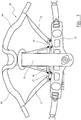
- FIG. 2 shows a rear view of a harness 10 according to an embodiment of the invention.
- the harness 10 includes a back plate 11, a waist belt 12, shoulder straps 13 and shoulder pads 14.
- Each shoulder strap 13 is attached to a respective one of the shoulder pads 14 at a first end, with each of the shoulder pads 14 being attached to an upper part of the back plate 11.
- each shoulder strap 13 is attached to a lower part of the back plate via a respective tension accommodating means 15 of a tension equalising mechanism.
- Each tension accommodating means lies substantially in the plane of the back plate.
- the tension accommodating means 15 are linked by a link rod 16, which floats freely between the two tension accommodating means.
- the link rod 16 may pass through a groove or recess 21 in the back plate, as can be seen in figure 3 .
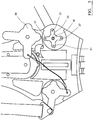
- the tension accommodating means comprises an L-shaped member having first and second arms 17, 18.
- the first arm 17 is disposed substantially perpendicular to the second arm 18.
- the shoulder strap 13 is connected to an end region of the first arm 17 and the link rod is connected to an end region of the second arm 18.
- the L-shaped member is pivotally connected to a part 19 of the back plate 11 at pivot point 20, which is positioned between its first and second arms. The L-shaped member can therefore rotate about the axis of the pivot (perpendicular to the plane of the back plate).
- the shoulder strap on one side of the harness effectively lengthens to reduce the tension caused by the wearer raising his arm on that side
- the other shoulder strap effectively shortens to increase the tension on the other, dropped shoulder, due to the mirror-image arrangement of the tension accommodating means 15.
- the wearer is able to lift his arms freely without hindrance from the harness, and is able to crawl without risk of either shoulder strap 13 falling off as his shoulders drop, because of the manner in which the tension in one shoulder strap 13 is transferred to the other shoulder strap.
- Figure 4 shows a portion of a harness according to another embodiment of the invention, namely the back plate 11 and shoulder straps 13 of the harness.
- the shoulder straps 13 are not connected to the upper part of the back plate 10 via shoulder pads 14, though of course they would be in the fully assembled harness.
- each tension accommodating means 30 is a pulley having first and second arms 31 and 32 disposed substantially at a right-angle with respect to one another.
- Each first arm 31 is connected to a respective shoulder strap 13 and each second arm 32 is connected to a common wire 33, which acts as a connecting element between the tension accommodating means 30.
- each tension accommodating means is pivotally connected to the back plate 11 about a respective pivot point 34, which is provided between the first and second arms of the tension accommodating means.
- FIG. 4 thus functions in a similar way to that of figures 2 and 3 described above. Namely, tension in one of the shoulder straps 13 causes the pivot arm 31 to which it is connected to be raised upwards, thus rotating the tension accommodating means 30 about its pivot point 34.
- the tension accommodating means 30 shown on the right of the figure will rotate anti-clockwise if tension is applied to its shoulder strap 13. This rotation effectively lengthens the shoulder strap 13 and enables the tension in the shoulder strap to be reduced, enabling the wearer to move freely.
- this rotation causes the arm 32 to rotate anti-clockwise also, which in turn pulls on the wire 33.
- the wire 33 is therefore put under tension and transfers the force (tension) to the tension accommodating means 30 on the left of the figure, rotating it in the anti-clockwise direction also.
- this tension accommodating means rotates, the shoulder strap 13 to which it is connected is pulled downwards, pulling the shoulder pad 14 more firmly against the wearer's shoulder on that side. In other words, tension is transferred from one of the shoulder straps to the other shoulder strap.
- Figure 5 shows a return device 35 as a biasing means in one of the tension accommodating means 30 shown in figure 4 .
- the return device has elastic properties and has a central hole through which a pivot pin 36 of the pivot point 34 passes, together with outer holes 37 on each of four arm regions.
- the outer holes 37 engage with corresponding protrusions on the underside of the tension accommodating means 30.
- the return device 35 acts to bias the tension accommodating means 30 towards a central return (neutral, rest) position.
- the tension accommodating means rotates, due to tension in the shoulder strap 13 or from the wire 33, it causes the arms of the return device to move also, through the engagement of its protrusions with the holes 37.
- the return device 35 acts to return the tension accommodating means to its original position. This occurs as the elastic arms of the return device seek to return to their original, un-deformed configuration.
- a biasing means could be provided for the harness of the embodiment of figures 2 and 3 also.
- the biasing means need not be a return part of the type described above. Any part having suitable elastic properties could be used, such as a spring (e.g. coil spring).
- a spring could, for example, be attached between a part of the L-shaped member, such as one of the arms, and a portion of the back plate.
- the tension accommodating means are disposed symmetrically about a central longitudinal axis of the back plate. In this way, a smooth and even adjustment of the shoulder straps is realised.
- a harness embodying the invention enables free independent movement of the wearer's arms and shoulders and transfers tension effectively from one shoulder strap to the other.
- the shoulder straps tighten and loosen alternately in synchronism with the user's movement, as the tension equalising mechanism is resiliently biased in a neutral configuration.
Landscapes
- Health & Medical Sciences (AREA)
- Pulmonology (AREA)
- General Health & Medical Sciences (AREA)
- Business, Economics & Management (AREA)
- Emergency Management (AREA)
- Emergency Lowering Means (AREA)
- Portable Outdoor Equipment (AREA)
Description
- The invention relates to a harness for use with breathing apparatus. In particular, the invention relates to a harness of the type worn by professional firefighters, though it may be applied to other sorts of harness, such as a diving harness, also.
- A known
harness 1 for use with breathing apparatus is shown inFigure 1 . The harness includes aback plate 2, awaist belt 3,shoulder straps 4 andshoulder pads 5. Agas cylinder 6 containing pressurised gas is mounted to theback plate 2. The weight of the harness and cylinder is transferred to the hips of the user through thewaist belt 3 and to the upper body of the user through theshoulder pads 5 andshoulder straps 4. - In this regard, each
shoulder strap 4 is attached in two places. Namely, at a first end to one of theshoulder pads 5 and at a second end to the lower part of theback plate 2. Each strap thus forms a loop, which takes some of the weight of the harness/cylinder unit and helps to hug the harness to the wearer's body. - The constant tension on the shoulders from the
shoulder straps 4 makes wearing theharness 1 noticeable and can cause fatigue. In addition, when the wearer lifts an arm into the air, theshoulder strap 4 goes into tension, restricting movement and causing the associatedshoulder pad 5 to dig into the wearer's shoulder. This is a particular problem when climbing ladders, reaching for high objects or crawling. - Furthermore, when the wearer is crawling one shoulder drops as the other arm is stretched out and this can cause tension in the
strap 4 on the shoulder which drops to be completely removed. The shoulder strap and associatedpad 5 can therefore fall off the shoulder making the unit unstable. - A known harness designed to alleviate the above problems is described in
US 6290111 . In this harness, the shoulder straps are attached to opposite sides of a rigid element provided at the lower part of the back plate. The rigid element is pivotally connected to the back plate at a central point between where the shoulder straps are attached. Thus, when the wearer raises one arm the tension in the associated shoulder strap causes the rigid element to rotate about the central point, helping to reduce the tension in the strap. Furthermore, rotation of the rigid element causes tension to be applied to the other shoulder strap, helping to prevent the tension in that shoulder strap from being removed. However, the above harness allows only a limited degree of movement in which tension in the straps is accommodated, and tension is not always maintained in both straps which can make the harness unstable. - It is therefore desirable to provide a harness which enables the wearer to perform a fuller range of movement, in comfort, and which prevents the harness from becoming unstable.
- According to the present invention, there is provided a harness for use with breathing apparatus, according to
claim 1. The resilient biasing of the tension equalising mechanism towards the neutral configuration ensures that the support straps move with the body and remain tense. In this way, the harness is prevented from becoming unstable. The tension equalising mechanism is arranged such that, when tension is no longer applied to the first strap, it acts to increase the tension in the first strap by decreasing the tension in the second strap and transferring the tension to the first strap. - Thus, the support straps are stopped from going slack and are always kept under tension, ensuring that the straps do not come off the user's shoulder during use of the harness.
- The tension equalising mechanism includes first and second tension accommodating means connected by a connecting element, wherein, when tension is applied to the first support strap, the first tension accommodating means acts to increase an effective length of the first support strap and to reduce the tension in the strap, and the tension is transferred via the connecting element to the second tension accommodating means, which acts to reduce an effective length of the second support strap and to increase the tension in the second support strap.
- The independent action of each of the first and second tension accommodating means on the first and second support straps, together with the connection therebetween, enables the wearer to perform a fuller range of movement and in greater comfort than previously possible. In addition, it ensures that the harness is stable when the user is crawling.
- By enabling the wearer to move more freely and with less restriction, the harness advantageously allows the wearer to concentrate on the task at hand without having to worry about pain and stress caused by carrying the weight of the cylinder in an uncomfortable manner.
- First biasing means for urging the first attachment means to a central return position and/or second biasing means for urging the second attachment means to a central return position are provided, so as to resiliently bias the tension equalising mechanism towards the neutral configuration. The biasing means may include an elastic return part such as a rubber return part or a spring.
- Advantageously, the biasing means provide a small, controlled resistance to the movement of the wearer, making the adjustment of the shoulder straps feel more natural and secure to the wearer and ensuring that adequate tension is always provided in the straps.
- Reference is now made, by way of example only, to the accompanying drawings, in which:
-
Figure 1 shows a known harness; -
Figure 2 shows a harness according to an embodiment of the invention; -
Figure 3 shows a portion of the harness offigure 2 ; -
Figure 4 shows a portion of a harness according to another embodiment of the invention; -
Figure 5 shows a return device as a biasing means in one of the attachment means shown infigure 4 . -
Figure 2 shows a rear view of aharness 10 according to an embodiment of the invention. Theharness 10 includes aback plate 11, awaist belt 12,shoulder straps 13 andshoulder pads 14. Eachshoulder strap 13 is attached to a respective one of theshoulder pads 14 at a first end, with each of theshoulder pads 14 being attached to an upper part of theback plate 11. At a second end, eachshoulder strap 13 is attached to a lower part of the back plate via a respective tension accommodating means 15 of a tension equalising mechanism. Each tension accommodating means lies substantially in the plane of the back plate. The tension accommodating means 15 are linked by alink rod 16, which floats freely between the two tension accommodating means. Thelink rod 16 may pass through a groove or recess 21 in the back plate, as can be seen infigure 3 . - One of the tension accommodating means is shown in greater detail in
Figure 3 . As can be seen, the tension accommodating means comprises an L-shaped member having first andsecond arms first arm 17 is disposed substantially perpendicular to thesecond arm 18. Theshoulder strap 13 is connected to an end region of thefirst arm 17 and the link rod is connected to an end region of thesecond arm 18. The L-shaped member is pivotally connected to apart 19 of theback plate 11 atpivot point 20, which is positioned between its first and second arms. The L-shaped member can therefore rotate about the axis of the pivot (perpendicular to the plane of the back plate). - Thus, when a wearer lifts his left arm (the shoulder strap shown in
figure 3 being for the wearer's left side), theshoulder strap 13 is put under tension. Theshoulder strap 13 in turn exerts a force on thepivot arm 17 urging the pivot arm upwards. Hence, the end region of thepivot arm 17 to which thestrap 13 is attached is caused to move upwards and the L-shaped member rotates about thepivot point 20 accordingly. In this way, the wearer is able to lift his arm freely because the increased tension in theshoulder strap 13 is accommodated (relieved) by the upward movement of thepivot arm 17, effectively lengthening theshoulder strap 13. - Furthermore, the resultant clockwise rotation of the L-shaped member causes the end region of the
arm 18 to which thelink rod 16 is connected to move downwards and rightwards towards theback plate 11. As thelink rod 16 moves in this fashion, the tension in theshoulder strap 13 from the lifting of the wearer's left arm is transferred to theshoulder strap 13 on the wearer's right-hand side. - In other words, as can be seen from
figure 2 , the movement of thelink rod 16 downwards and to the right causes the L-shaped tension accommodating means 15 on the other side of the back plate to undergo a clockwise rotation about itspivot point 20. This rotation causes the end of thepivot arm 17 of the L-shaped member to which theshoulder strap 13 is connected to move downwards, shortening an effective length of the shoulder strap and thus increasing the tension in theshoulder strap 13 and pulling the associatedshoulder pad 14 more firmly against the wearer's right shoulder. In this way, tension in the left shoulder strap is transferred to the right shoulder strap. Of course, the same occurs in reverse if the wearer lifts his right arm instead of his left arm. Hence, as the shoulder strap on one side of the harness effectively lengthens to reduce the tension caused by the wearer raising his arm on that side, the other shoulder strap effectively shortens to increase the tension on the other, dropped shoulder, due to the mirror-image arrangement of the tension accommodating means 15. - Thus, the wearer is able to lift his arms freely without hindrance from the harness, and is able to crawl without risk of either
shoulder strap 13 falling off as his shoulders drop, because of the manner in which the tension in oneshoulder strap 13 is transferred to the other shoulder strap. -
Figure 4 shows a portion of a harness according to another embodiment of the invention, namely theback plate 11 andshoulder straps 13 of the harness. In the figure, the shoulder straps 13 are not connected to the upper part of theback plate 10 viashoulder pads 14, though of course they would be in the fully assembled harness. - In this embodiment, each tension accommodating means 30 is a pulley having first and
second arms first arm 31 is connected to arespective shoulder strap 13 and eachsecond arm 32 is connected to acommon wire 33, which acts as a connecting element between thetension accommodating means 30. In addition, each tension accommodating means is pivotally connected to theback plate 11 about arespective pivot point 34, which is provided between the first and second arms of the tension accommodating means. - The embodiment of
figure 4 thus functions in a similar way to that offigures 2 and3 described above. Namely, tension in one of the shoulder straps 13 causes thepivot arm 31 to which it is connected to be raised upwards, thus rotating the tension accommodating means 30 about itspivot point 34. For example, the tension accommodating means 30 shown on the right of the figure will rotate anti-clockwise if tension is applied to itsshoulder strap 13. This rotation effectively lengthens theshoulder strap 13 and enables the tension in the shoulder strap to be reduced, enabling the wearer to move freely. - In addition, this rotation causes the
arm 32 to rotate anti-clockwise also, which in turn pulls on thewire 33. Thewire 33 is therefore put under tension and transfers the force (tension) to the tension accommodating means 30 on the left of the figure, rotating it in the anti-clockwise direction also. As this tension accommodating means rotates, theshoulder strap 13 to which it is connected is pulled downwards, pulling theshoulder pad 14 more firmly against the wearer's shoulder on that side. In other words, tension is transferred from one of the shoulder straps to the other shoulder strap. Of course, the same happens in reverse if tension is applied to the other shoulder strap initially. -
Figure 5 shows areturn device 35 as a biasing means in one of the tension accommodating means 30 shown infigure 4 . The return device has elastic properties and has a central hole through which apivot pin 36 of thepivot point 34 passes, together withouter holes 37 on each of four arm regions. Theouter holes 37 engage with corresponding protrusions on the underside of thetension accommodating means 30. - The
return device 35 acts to bias the tension accommodating means 30 towards a central return (neutral, rest) position. When the tension accommodating means rotates, due to tension in theshoulder strap 13 or from thewire 33, it causes the arms of the return device to move also, through the engagement of its protrusions with theholes 37. When tension is no longer applied to theshoulder strap 13 orwire 33 and the tension accommodating means is thus not caused to rotate further, thereturn device 35 acts to return the tension accommodating means to its original position. This occurs as the elastic arms of the return device seek to return to their original, un-deformed configuration. - A biasing means could be provided for the harness of the embodiment of
figures 2 and3 also. In addition, the biasing means need not be a return part of the type described above. Any part having suitable elastic properties could be used, such as a spring (e.g. coil spring). A spring could, for example, be attached between a part of the L-shaped member, such as one of the arms, and a portion of the back plate. - It is preferable that the tension accommodating means are disposed symmetrically about a central longitudinal axis of the back plate. In this way, a smooth and even adjustment of the shoulder straps is realised.
- As described above, a harness embodying the invention enables free independent movement of the wearer's arms and shoulders and transfers tension effectively from one shoulder strap to the other. When the wearer is climbing a ladder or crawling, the shoulder straps tighten and loosen alternately in synchronism with the user's movement, as the tension equalising mechanism is resiliently biased in a neutral configuration.
Claims (15)
- A harness (10) for use with breathing apparatus, comprising:a back plate (11);two support straps (13), each of which extends between an upper part of the back plate and a lower part of the back plate, the two support straps being disposed on opposite sides of a central axis of the back plate; anda tension equalising mechanism connected to the support straps and being arranged such that, when tension is applied to a first strap of the support straps, it acts to transfer the tension to the other, second strap, thereby increasing the tension in the second strap,characterised in that the tension equalising mechanism includes first and second tension accommodating means (15) which are disposed on opposite sides of the central axis of the back plate and are connected by a connecting element (16), wherein, when tension is applied to the first support strap, the first tension accommodating means acts to increase an effective length of the first support strap and to reduce the tension in the strap, and the tension is transferred via the connecting element to the second tension accommodating means, which acts to reduce an effective length of the second support strap and to increase the tension in the second support strap;wherein the first and second tension accommodating means (15) are axially and rotatably mounted to the back plate about first and second rotational axes, respectively, and act to reduce or increase the tension in the first or second support straps by rotation about the first and second rotational axes, respectively;the harness further comprising first biasing means (35) for urging the first tension accommodating means to a central return position and/or second biasing means for urging the second tension accommodating means to a central return position, so as to resiliently bias the tension equalising mechanism towards a neutral configuration.
- A harness according to claim 1, wherein the tension equalising mechanism is arranged such that, when tension is no longer applied to the first strap, it acts to increase the tension in the first strap by decreasing the tension in the second strap and transferring the tension to the first strap.
- A harness according to any preceding claim, wherein the first and second tension accommodating means (15) are connected to the first and second support straps, respectively.
- A harness according to any preceding claim, wherein the first tension accommodating means (15) and the second tension accommodating means (15) are disposed symmetrically with respect to the central axis of the back plate.
- A harness according to any preceding claim, wherein the first and second tension accommodating means (15) are provided substantially in the plane of the back plate.
- A harness according to any preceding claim, wherein the first and/or second tension accommodating means (15) is a pulley.
- A harness according to any preceding claim, wherein each tension accommodating means (15) has a first arm (17) to which its respective support strap is connected and a second arm (18) to which the connecting element is connected, the tension accommodating means being axially mounted to the back plate about a pivot point (20) between the first and second arms.
- A harness according to claim 7, wherein the first arm (17) is substantially perpendicular to the second arm (18).
- A harness according to any preceding claim, wherein the first or second biasing means (35) comprises an elastic return device attached to the first or second tension accommodating means, respectively.
- A harness according to claim 9, wherein the elastic return device comprises rubber.
- A harness according to any preceding claim, wherein the first or second biasing means (35) comprises a spring connected to the first or second tension accommodating means, respectively.
- A harness according to any preceding claim, wherein the first tension accommodating means (15), the second tension accommodating means (15) and the connecting element (16) are formed integrally.
- A harness according to any preceding claim, wherein the connecting element (16) comprises a rod or bar.
- A harness according to any of claims 1 to 12, wherein the connecting element comprises a wire (33).
- A harness according to any preceding claim, wherein each of the first and second support straps (13) comprises a shoulder pad (14) connected to the upper part of the back plate and a shoulder strap connected to the lower part of the back plate.
Applications Claiming Priority (1)
| Application Number | Priority Date | Filing Date | Title |
|---|---|---|---|
| GBGB0623719.2A GB0623719D0 (en) | 2006-11-28 | 2006-11-28 | A harness for use with breathing apparatus |
Publications (2)
| Publication Number | Publication Date |
|---|---|
| EP1927379A1 EP1927379A1 (en) | 2008-06-04 |
| EP1927379B1 true EP1927379B1 (en) | 2017-07-26 |
Family
ID=37671432
Family Applications (1)
| Application Number | Title | Priority Date | Filing Date |
|---|---|---|---|
| EP07121679.0A Not-in-force EP1927379B1 (en) | 2006-11-28 | 2007-11-27 | A harness for use with breathing apparatus |
Country Status (3)
| Country | Link |
|---|---|
| US (1) | US8020738B2 (en) |
| EP (1) | EP1927379B1 (en) |
| GB (1) | GB0623719D0 (en) |
Families Citing this family (12)
| Publication number | Priority date | Publication date | Assignee | Title |
|---|---|---|---|---|
| GB2470031B (en) * | 2009-05-06 | 2013-01-23 | Draeger Safety Uk Ltd | Clip for use with breathing apparatus |
| WO2011053961A2 (en) | 2009-11-02 | 2011-05-05 | C & P Hiam Associates Llc | Stable backpack |
| WO2012094499A1 (en) * | 2011-01-06 | 2012-07-12 | Illinois Tool Works Inc. | Personal equipment suspension system with active lumbar support |
| US9271559B2 (en) * | 2011-08-29 | 2016-03-01 | Mystery Ranch Limited | Body armor support harness |
| CA2861974A1 (en) * | 2012-01-19 | 2013-07-25 | Emerson Electric Co. | Articulated backpack apparatus and system |
| US9119975B2 (en) * | 2012-02-15 | 2015-09-01 | 3M Innovative Properties Company | Respirator waist belt |
| US9033616B2 (en) * | 2013-07-13 | 2015-05-19 | Sean Allen Krumhauer | Personal flotation device for a self contained breathing apparatus |
| US20200238110A1 (en) * | 2017-10-18 | 2020-07-30 | 3M Innovative Properties Company | Articulating Support Assembly For A Self-Contained Breathing Apparatus |
| US10806238B2 (en) * | 2018-05-15 | 2020-10-20 | Samsonite Ip Holdings S.A.R.L. | Backpack with dynamic flexible hip belt |
| WO2020041166A1 (en) | 2018-08-23 | 2020-02-27 | Phuong Nguyen | Harness for golf bag |
| WO2020236128A1 (en) * | 2019-05-21 | 2020-11-26 | Dezega Holding Ukraine, Llc | Belt harness system |
| EP3885004A1 (en) * | 2020-03-23 | 2021-09-29 | Draeger Safety UK Limited | Support |
Citations (2)
| Publication number | Priority date | Publication date | Assignee | Title |
|---|---|---|---|---|
| US4676418A (en) * | 1986-03-12 | 1987-06-30 | Lowe Alpine Systems, Inc. | Backpack having improved load distribution and stabilizing structures |
| US6290111B1 (en) * | 1996-02-21 | 2001-09-18 | Interspiro Ab | Harness |
Family Cites Families (14)
| Publication number | Priority date | Publication date | Assignee | Title |
|---|---|---|---|---|
| US2197427A (en) * | 1938-06-28 | 1940-04-16 | Despain Roy | Camper's pack |
| GB606022A (en) * | 1946-01-08 | 1948-08-05 | John Raymond Cuthbert Quilter | Improvements in safety or retaining devices for seats on aircraft and other vehicles |
| US3090621A (en) * | 1960-07-29 | 1963-05-21 | Heimers Rudolph Heinrich | Carrier means for attaching apparatus to the human body |
| GB2059750B (en) * | 1979-09-12 | 1983-04-13 | Chubb Panorama | Back-carrying harness assemblies |
| US5427290A (en) * | 1994-01-10 | 1995-06-27 | Ultimate Direction, Inc. | Water pouch backpack |
| US6070776A (en) * | 1997-08-08 | 2000-06-06 | Furnary; Kevin P. | Backpack load centering system |
| US6209111B1 (en) * | 1998-11-09 | 2001-03-27 | Microsoft Corporation | Error correction on a mobile device |
| FR2814045B1 (en) * | 2000-09-20 | 2002-12-27 | Promiles | BACKPACK EQUIPPED WITH AN ANGULAR SHOCK ABSORBER BETWEEN THE BACK OF THE BAG AND THE STRAP AND / OR BELT ASSEMBLY |
| US6607107B2 (en) * | 2001-02-02 | 2003-08-19 | Bonfire Snowboarding, Inc. | Backpack and improved load-carrying system therefor |
| US7367749B2 (en) * | 2003-11-19 | 2008-05-06 | Sancheong Co. Ltd. | Backpack |
| NZ536593A (en) * | 2004-11-17 | 2005-03-24 | Aarn Tate | Free shoulder movement harness system for backpacks |
| US8066164B2 (en) * | 2005-06-08 | 2011-11-29 | Gregory Mountain Products, Llc | Backpack having auto-adjusting waistbelt |
| CN2800884Y (en) * | 2005-06-30 | 2006-08-02 | 叶啓明 | Interdynamic balancing device |
| US7997466B2 (en) * | 2007-11-19 | 2011-08-16 | Nike, Inc. | Self stabilizing backpack |
-
2006
- 2006-11-28 GB GBGB0623719.2A patent/GB0623719D0/en not_active Ceased
-
2007
- 2007-11-27 EP EP07121679.0A patent/EP1927379B1/en not_active Not-in-force
- 2007-11-28 US US11/946,570 patent/US8020738B2/en not_active Expired - Fee Related
Patent Citations (2)
| Publication number | Priority date | Publication date | Assignee | Title |
|---|---|---|---|---|
| US4676418A (en) * | 1986-03-12 | 1987-06-30 | Lowe Alpine Systems, Inc. | Backpack having improved load distribution and stabilizing structures |
| US6290111B1 (en) * | 1996-02-21 | 2001-09-18 | Interspiro Ab | Harness |
Also Published As
| Publication number | Publication date |
|---|---|
| GB0623719D0 (en) | 2007-01-10 |
| US8020738B2 (en) | 2011-09-20 |
| US20080179367A1 (en) | 2008-07-31 |
| EP1927379A1 (en) | 2008-06-04 |
Similar Documents
| Publication | Publication Date | Title |
|---|---|---|
| US8020738B2 (en) | Harness for use with breathing apparatus | |
| US6802442B1 (en) | Backpack having a shoulder strap mounted lift buckle | |
| KR102583289B1 (en) | Human body flexion and extension assist device | |
| EP0885635B1 (en) | Swimming goggles with a device for regulating the length of a strap | |
| US8967332B2 (en) | Safety harness strap adjuster | |
| KR102063257B1 (en) | Suit type exoskeleton adjustable to body size of wearer and Suit type exoskeleton for knee power assistance | |
| US7802577B2 (en) | Harness for stretching the penis | |
| US20020068667A1 (en) | Training device | |
| US20100242233A1 (en) | Method of Adjusting a Strap of a Safety Harness | |
| CN100542446C (en) | Head covering and goggles | |
| US20090198164A1 (en) | Knee Brace | |
| US2528370A (en) | Device to prevent mouth breathing | |
| JP7235867B2 (en) | infant carrier | |
| KR102357711B1 (en) | Weight lifting belt for improving user convenience | |
| US20060191969A1 (en) | Pack and frame for pack | |
| US20210290421A1 (en) | Posture correcting apparatus | |
| WO2012167072A1 (en) | Orthotic device | |
| US7018038B2 (en) | Spectacle installation device and spectacle frame | |
| KR20210110500A (en) | Shoulder dislocation and subluxation prevent aid | |
| EP1712259A2 (en) | Harness | |
| KR20240165356A (en) | Head support system and method of use | |
| KR200373164Y1 (en) | A bag string | |
| CN1674807B (en) | Carrying bag | |
| EP1803487B1 (en) | Safety harness | |
| JP2022182257A (en) | Work support suit and traction device used therefor |
Legal Events
| Date | Code | Title | Description |
|---|---|---|---|
| PUAI | Public reference made under article 153(3) epc to a published international application that has entered the european phase |
Free format text: ORIGINAL CODE: 0009012 |
|
| AK | Designated contracting states |
Kind code of ref document: A1 Designated state(s): AT BE BG CH CY CZ DE DK EE ES FI FR GB GR HU IE IS IT LI LT LU LV MC MT NL PL PT RO SE SI SK TR |
|
| AX | Request for extension of the european patent |
Extension state: AL BA HR MK RS |
|
| AKX | Designation fees paid | ||
| REG | Reference to a national code |
Ref country code: DE Ref legal event code: 8566 |
|
| 17P | Request for examination filed |
Effective date: 20090309 |
|
| RBV | Designated contracting states (corrected) |
Designated state(s): AT BE BG CH CY CZ DE DK EE ES FI FR GB GR HU IE IS IT LI LT LU LV MC MT NL PL PT RO SE SI SK TR |
|
| 17Q | First examination report despatched |
Effective date: 20090420 |
|
| GRAP | Despatch of communication of intention to grant a patent |
Free format text: ORIGINAL CODE: EPIDOSNIGR1 |
|
| STAA | Information on the status of an ep patent application or granted ep patent |
Free format text: STATUS: GRANT OF PATENT IS INTENDED |
|
| RIC1 | Information provided on ipc code assigned before grant |
Ipc: A45F 3/04 20060101ALN20170201BHEP Ipc: B63C 11/22 20060101ALN20170201BHEP Ipc: A45F 3/10 20060101ALI20170201BHEP Ipc: A62B 9/04 20060101AFI20170201BHEP |
|
| INTG | Intention to grant announced |
Effective date: 20170301 |
|
| RIN1 | Information on inventor provided before grant (corrected) |
Inventor name: STOREY, DAVID GRAHAM |
|
| GRAS | Grant fee paid |
Free format text: ORIGINAL CODE: EPIDOSNIGR3 |
|
| GRAA | (expected) grant |
Free format text: ORIGINAL CODE: 0009210 |
|
| STAA | Information on the status of an ep patent application or granted ep patent |
Free format text: STATUS: THE PATENT HAS BEEN GRANTED |
|
| AK | Designated contracting states |
Kind code of ref document: B1 Designated state(s): AT BE BG CH CY CZ DE DK EE ES FI FR GB GR HU IE IS IT LI LT LU LV MC MT NL PL PT RO SE SI SK TR |
|
| REG | Reference to a national code |
Ref country code: GB Ref legal event code: FG4D |
|
| REG | Reference to a national code |
Ref country code: CH Ref legal event code: EP |
|
| REG | Reference to a national code |
Ref country code: AT Ref legal event code: REF Ref document number: 911912 Country of ref document: AT Kind code of ref document: T Effective date: 20170815 |
|
| REG | Reference to a national code |
Ref country code: IE Ref legal event code: FG4D |
|
| REG | Reference to a national code |
Ref country code: DE Ref legal event code: R096 Ref document number: 602007051750 Country of ref document: DE |
|
| REG | Reference to a national code |
Ref country code: NL Ref legal event code: FP |
|
| REG | Reference to a national code |
Ref country code: LT Ref legal event code: MG4D |
|
| REG | Reference to a national code |
Ref country code: AT Ref legal event code: MK05 Ref document number: 911912 Country of ref document: AT Kind code of ref document: T Effective date: 20170726 |
|
| PG25 | Lapsed in a contracting state [announced via postgrant information from national office to epo] |
Ref country code: SE Free format text: LAPSE BECAUSE OF FAILURE TO SUBMIT A TRANSLATION OF THE DESCRIPTION OR TO PAY THE FEE WITHIN THE PRESCRIBED TIME-LIMIT Effective date: 20170726 Ref country code: AT Free format text: LAPSE BECAUSE OF FAILURE TO SUBMIT A TRANSLATION OF THE DESCRIPTION OR TO PAY THE FEE WITHIN THE PRESCRIBED TIME-LIMIT Effective date: 20170726 Ref country code: FI Free format text: LAPSE BECAUSE OF FAILURE TO SUBMIT A TRANSLATION OF THE DESCRIPTION OR TO PAY THE FEE WITHIN THE PRESCRIBED TIME-LIMIT Effective date: 20170726 Ref country code: LT Free format text: LAPSE BECAUSE OF FAILURE TO SUBMIT A TRANSLATION OF THE DESCRIPTION OR TO PAY THE FEE WITHIN THE PRESCRIBED TIME-LIMIT Effective date: 20170726 |
|
| PG25 | Lapsed in a contracting state [announced via postgrant information from national office to epo] |
Ref country code: LV Free format text: LAPSE BECAUSE OF FAILURE TO SUBMIT A TRANSLATION OF THE DESCRIPTION OR TO PAY THE FEE WITHIN THE PRESCRIBED TIME-LIMIT Effective date: 20170726 Ref country code: ES Free format text: LAPSE BECAUSE OF FAILURE TO SUBMIT A TRANSLATION OF THE DESCRIPTION OR TO PAY THE FEE WITHIN THE PRESCRIBED TIME-LIMIT Effective date: 20170726 Ref country code: BG Free format text: LAPSE BECAUSE OF FAILURE TO SUBMIT A TRANSLATION OF THE DESCRIPTION OR TO PAY THE FEE WITHIN THE PRESCRIBED TIME-LIMIT Effective date: 20171026 Ref country code: PL Free format text: LAPSE BECAUSE OF FAILURE TO SUBMIT A TRANSLATION OF THE DESCRIPTION OR TO PAY THE FEE WITHIN THE PRESCRIBED TIME-LIMIT Effective date: 20170726 Ref country code: IS Free format text: LAPSE BECAUSE OF FAILURE TO SUBMIT A TRANSLATION OF THE DESCRIPTION OR TO PAY THE FEE WITHIN THE PRESCRIBED TIME-LIMIT Effective date: 20171126 Ref country code: GR Free format text: LAPSE BECAUSE OF FAILURE TO SUBMIT A TRANSLATION OF THE DESCRIPTION OR TO PAY THE FEE WITHIN THE PRESCRIBED TIME-LIMIT Effective date: 20171027 |
|
| PG25 | Lapsed in a contracting state [announced via postgrant information from national office to epo] |
Ref country code: RO Free format text: LAPSE BECAUSE OF FAILURE TO SUBMIT A TRANSLATION OF THE DESCRIPTION OR TO PAY THE FEE WITHIN THE PRESCRIBED TIME-LIMIT Effective date: 20170726 Ref country code: CZ Free format text: LAPSE BECAUSE OF FAILURE TO SUBMIT A TRANSLATION OF THE DESCRIPTION OR TO PAY THE FEE WITHIN THE PRESCRIBED TIME-LIMIT Effective date: 20170726 Ref country code: DK Free format text: LAPSE BECAUSE OF FAILURE TO SUBMIT A TRANSLATION OF THE DESCRIPTION OR TO PAY THE FEE WITHIN THE PRESCRIBED TIME-LIMIT Effective date: 20170726 |
|
| REG | Reference to a national code |
Ref country code: DE Ref legal event code: R097 Ref document number: 602007051750 Country of ref document: DE |
|
| PG25 | Lapsed in a contracting state [announced via postgrant information from national office to epo] |
Ref country code: EE Free format text: LAPSE BECAUSE OF FAILURE TO SUBMIT A TRANSLATION OF THE DESCRIPTION OR TO PAY THE FEE WITHIN THE PRESCRIBED TIME-LIMIT Effective date: 20170726 Ref country code: SK Free format text: LAPSE BECAUSE OF FAILURE TO SUBMIT A TRANSLATION OF THE DESCRIPTION OR TO PAY THE FEE WITHIN THE PRESCRIBED TIME-LIMIT Effective date: 20170726 Ref country code: IT Free format text: LAPSE BECAUSE OF FAILURE TO SUBMIT A TRANSLATION OF THE DESCRIPTION OR TO PAY THE FEE WITHIN THE PRESCRIBED TIME-LIMIT Effective date: 20170726 |
|
| PLBE | No opposition filed within time limit |
Free format text: ORIGINAL CODE: 0009261 |
|
| STAA | Information on the status of an ep patent application or granted ep patent |
Free format text: STATUS: NO OPPOSITION FILED WITHIN TIME LIMIT |
|
| PG25 | Lapsed in a contracting state [announced via postgrant information from national office to epo] |
Ref country code: MC Free format text: LAPSE BECAUSE OF FAILURE TO SUBMIT A TRANSLATION OF THE DESCRIPTION OR TO PAY THE FEE WITHIN THE PRESCRIBED TIME-LIMIT Effective date: 20170726 |
|
| 26N | No opposition filed |
Effective date: 20180430 |
|
| PG25 | Lapsed in a contracting state [announced via postgrant information from national office to epo] |
Ref country code: CH Free format text: LAPSE BECAUSE OF NON-PAYMENT OF DUE FEES Effective date: 20171130 Ref country code: LI Free format text: LAPSE BECAUSE OF NON-PAYMENT OF DUE FEES Effective date: 20171130 |
|
| PG25 | Lapsed in a contracting state [announced via postgrant information from national office to epo] |
Ref country code: SI Free format text: LAPSE BECAUSE OF FAILURE TO SUBMIT A TRANSLATION OF THE DESCRIPTION OR TO PAY THE FEE WITHIN THE PRESCRIBED TIME-LIMIT Effective date: 20170726 Ref country code: LU Free format text: LAPSE BECAUSE OF NON-PAYMENT OF DUE FEES Effective date: 20171127 |
|
| REG | Reference to a national code |
Ref country code: FR Ref legal event code: ST Effective date: 20180731 Ref country code: BE Ref legal event code: MM Effective date: 20171130 |
|
| REG | Reference to a national code |
Ref country code: IE Ref legal event code: MM4A |
|
| PG25 | Lapsed in a contracting state [announced via postgrant information from national office to epo] |
Ref country code: MT Free format text: LAPSE BECAUSE OF NON-PAYMENT OF DUE FEES Effective date: 20171127 |
|
| PG25 | Lapsed in a contracting state [announced via postgrant information from national office to epo] |
Ref country code: FR Free format text: LAPSE BECAUSE OF NON-PAYMENT OF DUE FEES Effective date: 20171130 Ref country code: IE Free format text: LAPSE BECAUSE OF NON-PAYMENT OF DUE FEES Effective date: 20171127 |
|
| PG25 | Lapsed in a contracting state [announced via postgrant information from national office to epo] |
Ref country code: BE Free format text: LAPSE BECAUSE OF NON-PAYMENT OF DUE FEES Effective date: 20171130 |
|
| PG25 | Lapsed in a contracting state [announced via postgrant information from national office to epo] |
Ref country code: HU Free format text: LAPSE BECAUSE OF FAILURE TO SUBMIT A TRANSLATION OF THE DESCRIPTION OR TO PAY THE FEE WITHIN THE PRESCRIBED TIME-LIMIT; INVALID AB INITIO Effective date: 20071127 |
|
| PG25 | Lapsed in a contracting state [announced via postgrant information from national office to epo] |
Ref country code: CY Free format text: LAPSE BECAUSE OF NON-PAYMENT OF DUE FEES Effective date: 20170726 |
|
| PG25 | Lapsed in a contracting state [announced via postgrant information from national office to epo] |
Ref country code: TR Free format text: LAPSE BECAUSE OF FAILURE TO SUBMIT A TRANSLATION OF THE DESCRIPTION OR TO PAY THE FEE WITHIN THE PRESCRIBED TIME-LIMIT Effective date: 20170726 |
|
| PG25 | Lapsed in a contracting state [announced via postgrant information from national office to epo] |
Ref country code: PT Free format text: LAPSE BECAUSE OF FAILURE TO SUBMIT A TRANSLATION OF THE DESCRIPTION OR TO PAY THE FEE WITHIN THE PRESCRIBED TIME-LIMIT Effective date: 20170726 |
|
| PGFP | Annual fee paid to national office [announced via postgrant information from national office to epo] |
Ref country code: NL Payment date: 20201119 Year of fee payment: 14 |
|
| REG | Reference to a national code |
Ref country code: DE Ref legal event code: R082 Ref document number: 602007051750 Country of ref document: DE Representative=s name: HL KEMPNER PATENTANWALT, RECHTSANWALT, SOLICIT, DE |
|
| PGFP | Annual fee paid to national office [announced via postgrant information from national office to epo] |
Ref country code: DE Payment date: 20201119 Year of fee payment: 14 Ref country code: GB Payment date: 20201119 Year of fee payment: 14 |
|
| REG | Reference to a national code |
Ref country code: DE Ref legal event code: R119 Ref document number: 602007051750 Country of ref document: DE |
|
| REG | Reference to a national code |
Ref country code: NL Ref legal event code: MM Effective date: 20211201 |
|
| GBPC | Gb: european patent ceased through non-payment of renewal fee |
Effective date: 20211127 |
|
| PG25 | Lapsed in a contracting state [announced via postgrant information from national office to epo] |
Ref country code: NL Free format text: LAPSE BECAUSE OF NON-PAYMENT OF DUE FEES Effective date: 20211201 |
|
| PG25 | Lapsed in a contracting state [announced via postgrant information from national office to epo] |
Ref country code: GB Free format text: LAPSE BECAUSE OF NON-PAYMENT OF DUE FEES Effective date: 20211127 Ref country code: DE Free format text: LAPSE BECAUSE OF NON-PAYMENT OF DUE FEES Effective date: 20220601 |