EP1927369B1 - Device for displaying and measuring air losses in a chest drainage apparatus - Google Patents
Device for displaying and measuring air losses in a chest drainage apparatus Download PDFInfo
- Publication number
- EP1927369B1 EP1927369B1 EP07022515A EP07022515A EP1927369B1 EP 1927369 B1 EP1927369 B1 EP 1927369B1 EP 07022515 A EP07022515 A EP 07022515A EP 07022515 A EP07022515 A EP 07022515A EP 1927369 B1 EP1927369 B1 EP 1927369B1
- Authority
- EP
- European Patent Office
- Prior art keywords
- air
- bell
- outflow
- outlet section
- liquid
- Prior art date
- Legal status (The legal status is an assumption and is not a legal conclusion. Google has not performed a legal analysis and makes no representation as to the accuracy of the status listed.)
- Not-in-force
Links
Images


Classifications
-
- A—HUMAN NECESSITIES
- A61—MEDICAL OR VETERINARY SCIENCE; HYGIENE
- A61M—DEVICES FOR INTRODUCING MEDIA INTO, OR ONTO, THE BODY; DEVICES FOR TRANSDUCING BODY MEDIA OR FOR TAKING MEDIA FROM THE BODY; DEVICES FOR PRODUCING OR ENDING SLEEP OR STUPOR
- A61M1/00—Suction or pumping devices for medical purposes; Devices for carrying-off, for treatment of, or for carrying-over, body-liquids; Drainage systems
- A61M1/60—Containers for suction drainage, adapted to be used with an external suction source
- A61M1/61—Two- or three-bottle systems for underwater drainage, e.g. for chest cavity drainage
Definitions
- the present invention relates to a device for displaying and measuring air losses in a chest drainage apparatus.
- chest drainage consists in applying, after surgery or trauma, a tube which is connected to the chest cavity of a patient in order to allow exuded liquids and air losses to be conveyed to an appropriate apparatus.
- a device which is particularly widespread in the background art has, for example, a plurality of bubbling ports which are arranged at different distances from where any air losses arrive in the liquid, and this device is capable of providing qualitative information regarding the behavior over time of the extent of such losses by observing the number of ports affected by the phenomenon.
- Such a device is disclosed, for example, in US 6 338 728 .
- the aim of the present invention is therefore to provide a device of a physical type which, inserted in a chest drainage apparatus, is capable not only of giving a qualitative indication regarding any presence of air losses but also of measuring the flow-rate of such losses.
- the reference numeral 1 generally designates a chest drainage apparatus, which is provided with an enclosure with transparent windows, not shown in the figures, and comprises a union 2 for connection to an end of a tube 3 which is designed to be connected, at its other end, to the chest cavity of a patient to convey exuded liquids and air losses.
- the black arrows of Figures 3 and 5 represent the flow that the exuded liquids follow within the apparatus to reach in a known manner a collection vessel on the bottom of such apparatus.
- the flow of the air losses is represented by the white arrows and is conveyed by means of a duct 4 to the device according to the invention.
- Such device comprises a chamber 5, which is arranged at one of the transparent windows, which contains liquid 6, very commonly water, on a bottom 5a, and comprises at such bottom an outlet section 4a of the duct 4 which conveys the air losses.
- a bell 7 is provided within the chamber 5 in a position which lies above the outlet section 4a and with the lower edge in contact with the bottom 5a.
- Such bell which is immersed in the liquid 6 at the lower area, is provided at such area with a constantly open air outflow port 8, which is arranged distant from the region directly above the outlet section 4a, while in said region there is an air outflow port 9, which is provided with opening and closure means which are constituted by a cock 10, which comprises a hollow cylinder 10a provided with a hole 10b which is adapted to rotate about its own axis between the two positions shown in Figures 4 and 6 with the hole 10b respectively arranged and not arranged at a hole 9a provided in the wall of the port 9, by manual actuation on a tab 10c, which in Figure 2 is shown in a solid line in the position shown in Figures 3 and 4 and with dot-and-dash lines in the position of Figures 5 and 6 .
- a cock 10 which comprises a hollow cylinder 10a provided with a hole 10b which is adapted to rotate about its own axis between the two positions shown in Figures 4 and 6 with the hole 10b respectively arranged and not arranged at
- liquid 6 is used at the base of the seal which comprises the duct 4 so as to act as a backflow blocking valve, which is adapted to prevent the inflow of air at atmospheric pressure into the pleural cavity of the patient, in order to avoid the risk of lung collapse.
- the port 9 is normally open, and therefore the situation shown in Figures 3 and 4 occurs in which the air loss is visualized by the bubbling of the liquid 6 in the bell.
- the time required to empty the bell which has a known volume, is obviously proportional with an extremely simple ratio and can be tabulated with the flow-rate of the air loss and is timed by the physician, who is thus immediately aware of the measurement of the flow-rate.
- FIGS 7, 8, 9 illustrate a device according to another embodiment, which is again comprised within a chest drainage apparatus 12 of the type described previously.
- Such device comprises a chamber 13, which contains liquid 14 on a bottom 13a, and comprises, at an end of such bottom, an outflow section 15a of a duct 15 which conveys the air losses.
- a bell 16 in a position which lies above a section 15a and is totally immersed in the liquid 14; the bell is provided with an air outlet port 17, which is always open and is arranged at the opposite end with respect to the one that lies above the outflow section 15a, and with the plurality of air discharge ports 18, 19, 20, 21, 22, 23, which are distributed substantially uniformly and are provided with corresponding opening and closure cocks 23a for the port 23, with simultaneous manual actuation.
- the physician can measure, as shown earlier, the value of the flow-rate of the air losses, deducing it from the time, which can be total or partial by utilizing the level graduation, required to empty the liquid 14 from the bell 16 through the port 17, as shown in Figure 9 .
Landscapes
- Health & Medical Sciences (AREA)
- Heart & Thoracic Surgery (AREA)
- Biomedical Technology (AREA)
- Vascular Medicine (AREA)
- Engineering & Computer Science (AREA)
- Anesthesiology (AREA)
- Pulmonology (AREA)
- Hematology (AREA)
- Life Sciences & Earth Sciences (AREA)
- Animal Behavior & Ethology (AREA)
- General Health & Medical Sciences (AREA)
- Public Health (AREA)
- Veterinary Medicine (AREA)
- External Artificial Organs (AREA)
- Compressor (AREA)
Abstract
Description
- The present invention relates to a device for displaying and measuring air losses in a chest drainage apparatus.
- It is known that chest drainage consists in applying, after surgery or trauma, a tube which is connected to the chest cavity of a patient in order to allow exuded liquids and air losses to be conveyed to an appropriate apparatus.
- While the exuded liquids are collected within such apparatus, the air losses, if present, are currently made to pass, before being evacuated from the apparatus, through a device which indeed indicates their presence by utilizing the bubbling of air bubbles within a vessel filled with liquid, usually water or physiological solution.
- A device which is particularly widespread in the background art has, for example, a plurality of bubbling ports which are arranged at different distances from where any air losses arrive in the liquid, and this device is capable of providing qualitative information regarding the behavior over time of the extent of such losses by observing the number of ports affected by the phenomenon.
- Such a device is disclosed, for example, in
US 6 338 728 . - All currently known devices of the physical type provide, as seen for the one mentioned above, simply qualitative and instantaneous indications regarding the presence of any air losses, but today it has become important, as a consequence of research that medicine is conducting in this field, to know precisely the value of the flow-rate of such losses.
- The aim of the present invention is therefore to provide a device of a physical type which, inserted in a chest drainage apparatus, is capable not only of giving a qualitative indication regarding any presence of air losses but also of measuring the flow-rate of such losses.
- This aim is achieved by a chest drainage apparatus and a device for displaying and measuring air losses that have the features set forth in
claims 1 and 8, respectively. - Further characteristics and advantages will become better apparent from the description of two preferred but not exclusive embodiments of the device according to the invention, illustrated by way of non-limiting example in the accompanying drawings, wherein:
-
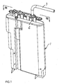
Figure 1 is a perspective view, taken from the front part, of a chest drainage apparatus which comprises the device according to the invention; -
Figure 2 is a perspective view, taken from the rear part, of the apparatus ofFigure 1 ; -
Figure 3 is a sectional view, taken along the line III-III ofFigure 1 , in a specific functional situation, as will become better apparent hereinafter; -
Figure 4 is a view of the detail comprised in the circle shown inFigure 3 ; -
Figure 5 is a sectional view, as inFigure 3 , but in a different functional situation; -
Figure 6 is a view of the detail comprised in the circle shown inFigure 5 ; -
Figure 7 is a sectional view of another embodiment of the device according to the invention; -
Figure 8 is a view of the detail comprised in the circle shown inFigure 7 ; -
Figure 9 is a view of the same detail ofFigure 8 , but in a different functional situation. - With reference to
Figures 1 to 6 , the reference numeral 1 generally designates a chest drainage apparatus, which is provided with an enclosure with transparent windows, not shown in the figures, and comprises aunion 2 for connection to an end of atube 3 which is designed to be connected, at its other end, to the chest cavity of a patient to convey exuded liquids and air losses. - The black arrows of
Figures 3 and5 represent the flow that the exuded liquids follow within the apparatus to reach in a known manner a collection vessel on the bottom of such apparatus. - The flow of the air losses is represented by the white arrows and is conveyed by means of a
duct 4 to the device according to the invention. - Such device comprises a
chamber 5, which is arranged at one of the transparent windows, which containsliquid 6, very commonly water, on a bottom 5a, and comprises at such bottom anoutlet section 4a of theduct 4 which conveys the air losses. - A
bell 7 is provided within thechamber 5 in a position which lies above theoutlet section 4a and with the lower edge in contact with the bottom 5a. - Such bell, which is immersed in the
liquid 6 at the lower area, is provided at such area with a constantly openair outflow port 8, which is arranged distant from the region directly above theoutlet section 4a, while in said region there is anair outflow port 9, which is provided with opening and closure means which are constituted by acock 10, which comprises ahollow cylinder 10a provided with ahole 10b which is adapted to rotate about its own axis between the two positions shown inFigures 4 and6 with thehole 10b respectively arranged and not arranged at a hole 9a provided in the wall of theport 9, by manual actuation on atab 10c, which inFigure 2 is shown in a solid line in the position shown inFigures 3 and 4 and with dot-and-dash lines in the position ofFigures 5 and 6 . - The air that exits from the bell both by means of the
port 8 and by means of theport 9, depending on the functional step that occurs as described hereafter, reaches the upper portion of thechamber 5, which is provided with anevacuation union 11. - Finally, it is noted that the
liquid 6 is used at the base of the seal which comprises theduct 4 so as to act as a backflow blocking valve, which is adapted to prevent the inflow of air at atmospheric pressure into the pleural cavity of the patient, in order to avoid the risk of lung collapse. - In the operation of the invention, the
port 9 is normally open, and therefore the situation shown inFigures 3 and 4 occurs in which the air loss is visualized by the bubbling of theliquid 6 in the bell. - When the physician wishes to pass from a simple visualization of the air loss to the measurement of such loss, he closes the
port 9 by operating thecock 10 and thus reaches the situation shown inFigures 5 and 6 . - The air bubbles, which by their own nature tend to rise, now encounter an obstacle in the wall of the
bell 7, thus producing an action on the part of the air for emptying the liquid from the bell through theport 8 until the situation ofFigure 5 is reached - The time required to empty the bell, which has a known volume, is obviously proportional with an extremely simple ratio and can be tabulated with the flow-rate of the air loss and is timed by the physician, who is thus immediately aware of the measurement of the flow-rate.
- Moreover, it should be noted that even during this step, the display of the air loss, shown by the bubbling of the liquid, is not lost.
-
Figures 7, 8, 9 illustrate a device according to another embodiment, which is again comprised within achest drainage apparatus 12 of the type described previously. - Such device comprises a
chamber 13, which containsliquid 14 on abottom 13a, and comprises, at an end of such bottom, anoutflow section 15a of aduct 15 which conveys the air losses. - Within the
chamber 13 there is abell 16, in a position which lies above asection 15a and is totally immersed in theliquid 14; the bell is provided with anair outlet port 17, which is always open and is arranged at the opposite end with respect to the one that lies above theoutflow section 15a, and with the plurality ofair discharge ports port 23, with simultaneous manual actuation. - Finally, attention is directed to the presence of a graduation of the level of the liquid contained in the bell in order to offer particular operating modes to users.
- Operation of the embodiment now described repeats the conditions described earlier.
- With the
cocks 23a open, as shown inFigures 7 and 8 , the air losses are displayed by bubbling in theliquid 14 in the known comparative manner, and therefore massive air losses are matched by bubbling at all theports 17 to 23, while progressive reduction of such losses is made evident by the progressive reduction of the affected ports, until for extremely small losses it is reduced to bubbling only at theport 23. - By closing simultaneously the
cocks 23a, the physician can measure, as shown earlier, the value of the flow-rate of the air losses, deducing it from the time, which can be total or partial by utilizing the level graduation, required to empty theliquid 14 from thebell 16 through theport 17, as shown inFigure 9 . - The described invention is susceptible of numerous other modifications and variations, all of which are within the scope of the appended claims; all the details may further be replaced with other technically equivalent elements.
- Where technical features mentioned in any claim are followed by reference signs, those reference signs have been included for the sole purpose of increasing the intelligibility of the claims and accordingly, such reference signs do not have any limiting effect on the interpretation of each element identified by way of example by such reference signs.
Claims (8)
- A chest drainage apparatus comprising an enclosure with transparent windows provided with a union (2) for connection to an end of a tube (3) which is designed to be connected, at the other end, to the chest cavity of a patient to convey exuded liquids and air losses to the apparatus, a vessel for collecting said liquids, and a device for displaying and measuring the air losses, the device comprising, within the apparatus (1) and at one of said transparent windows: a chamber (5, 13) which contains liquid (6, 14) on the bottom (5a, 13a); an outlet section (4a, 5a) of a duct (4, 15) for conveying said air losses; a bell (7, 16) which is arranged above said outlet section (4a, 15a), is immersed in said liquid at least at a lower end area and is provided, at a submerged portion, with at least one always-open port (8, 17) for the outflow of air which is not comprised within the portion of the surface of said bell (7, 16) that lies directly above said outlet section (4a, 15a), characterized in that the device further comprises at least one additional port (9, 18-23) for the outflow of air, which is provided with opening and closure means (10, 23a) that are operatable in the closed position for enabling measurement of the air losses, said at least one additional port (9, 18-23) for the outflow of the air from the bell (7, 16) being connected to the upper portion of said liquid containment chamber (5, 13), which is connected to an evacuation union (11).
- The apparatus according to claim 1, characterized in that the bell (7) comprises a single air outflow port (9), which is provided with opening and closure means (10) and is arranged above the outlet section (4a) of the duct (4) for conveying air losses.
- The apparatus according to one of the preceding claims, characterized in that the chamber (5) that contains liquid (6) comprises the outlet section (4a) of the duct (4) for conveying air losses at the bottom (5a), and in that the bell (7) has its lower rim in contact with said bottom (5a), said bell (7) being provided with a said always-open port (8) for the outflow of the air located within the lower end area immersed in the liquid (6) in a position which is spaced from said outlet section (4a), and with a said air outflow port (9) provided with the opening and closure means (10) that is located in a position which lies above said outlet section (4a).
- The apparatus according to claim 1, characterized in that the chamber (13) that contains liquid (14) comprises the outlet section (15a) of the duct (15) for conveying air losses at one end of the bottom (13a), and in that the bell (16) is provided with a said always-open port (17) for the outflow of the air located above the other end, and with a plurality of said ports (18-23) for the outflow of the air which are provided with means (23a) for opening and closure with simultaneous actuation which are aligned and distributed substantially uniformly starting from the always-open port (17) to the region that lies above said outlet section (15a).
- The apparatus according to one of the claims 1 or 4, characterized in that the bell (16) is provided with a graduation of the level of the liquid (14) contained therein.
- The apparatus according to one of the claims 1-3, characterized in that the means for opening and closing an air outflow port comprise a manually-actuated cock (10).
- The apparatus according to one or more of the preceding claims comprising the device for displaying and measuring the air losses and provided with a valve for preventing backflow with a liquid seal, wherein said chamber (5, 13) containing liquid (6, 14) on the bottom (5a, 13a) constitutes the base of said valve.
- A device for displaying and measuring air losses for a chest drainage apparatus as set forth in the preceding claims, that is comprisable within the apparatus and comprises: a chamber (5, 13) which contains liquid (6, 14) on the bottom (5a, 13a); an outlet section (4a, 5a) of a duct (4, 15) for conveying said air losses; a bell (7, 16) which is arranged above said outlet section (4a, 15a), is immersed in said liquid at least at a lower end area and is provided, at a submerged portion, with at least one always-open port (8, 17) for the outflow of air which is not comprised within the portion of the surface of said bell (7, 16) that lies directly above said outlet section (4a, 15a), characterized in that it further comprises at least one additional port (9, 18-23) for the outflow of air, which is provided with opening and closure means (10, 23a) that are operatable in the closed position for enabling measurement of the air losses, said at least one additional port (9, 18-23) for the outflow of the air from the bell (7, 16) being connected to the upper portion of said liquid containment chamber (5, 13), which is connected to an evacuation union (11).
Applications Claiming Priority (1)
| Application Number | Priority Date | Filing Date | Title |
|---|---|---|---|
| IT002291A ITMI20062291A1 (en) | 2006-11-28 | 2006-11-28 | DISPLAY AND MEASUREMENT DEVICE FOR AIR LOSSES IN THE THORACIC DRAINAGE APPLIANCE. |
Publications (3)
| Publication Number | Publication Date |
|---|---|
| EP1927369A1 EP1927369A1 (en) | 2008-06-04 |
| EP1927369A8 EP1927369A8 (en) | 2008-08-06 |
| EP1927369B1 true EP1927369B1 (en) | 2010-03-17 |
Family
ID=38983532
Family Applications (1)
| Application Number | Title | Priority Date | Filing Date |
|---|---|---|---|
| EP07022515A Not-in-force EP1927369B1 (en) | 2006-11-28 | 2007-11-20 | Device for displaying and measuring air losses in a chest drainage apparatus |
Country Status (6)
| Country | Link |
|---|---|
| US (1) | US8166802B2 (en) |
| EP (1) | EP1927369B1 (en) |
| AT (1) | ATE460952T1 (en) |
| DE (1) | DE602007005329D1 (en) |
| IT (1) | ITMI20062291A1 (en) |
| WO (1) | WO2008064804A1 (en) |
Families Citing this family (4)
| Publication number | Priority date | Publication date | Assignee | Title |
|---|---|---|---|---|
| ITMI20071648A1 (en) * | 2007-08-08 | 2009-02-09 | Eurosets Srl | THORACIC DRAINAGE DEVICE. |
| ITMI20071649A1 (en) * | 2007-08-08 | 2009-02-09 | Eurosets Srl | THORACIC DRAINAGE DEVICE. |
| IT1390718B1 (en) * | 2008-07-11 | 2011-09-15 | Andrea Gibertoni | DEVICE FOR THORACIC DRAINAGE WITH SUCTION MEANS |
| US8882678B2 (en) | 2009-03-13 | 2014-11-11 | Atrium Medical Corporation | Pleural drainage system and method of use |
Family Cites Families (5)
| Publication number | Priority date | Publication date | Assignee | Title |
|---|---|---|---|---|
| US3363627A (en) | 1966-10-20 | 1968-01-16 | Deknatel Inc | Underwater drainage apparatus |
| US3559647A (en) * | 1968-06-05 | 1971-02-02 | Deknatel Inc | Controllable underwater drainage apparatus |
| US4772277A (en) * | 1987-08-20 | 1988-09-20 | Vanderbilt University | Chest cavity evacuation apparatus with resettable air volume meter |
| US5989234A (en) * | 1997-01-14 | 1999-11-23 | Deknatel Technology Corporation | Device and system for draining a body cavity and methods related thereto |
| IT1308959B1 (en) * | 1999-11-18 | 2002-01-15 | Eurosets Srl | POST-OPERATIONAL SELF-TRANSFUSION DEVICE, PARTICULARLY INCARDIOUS SURGERY |
-
2006
- 2006-11-28 IT IT002291A patent/ITMI20062291A1/en unknown
-
2007
- 2007-11-20 WO PCT/EP2007/010043 patent/WO2008064804A1/en not_active Ceased
- 2007-11-20 AT AT07022515T patent/ATE460952T1/en not_active IP Right Cessation
- 2007-11-20 DE DE602007005329T patent/DE602007005329D1/en active Active
- 2007-11-20 EP EP07022515A patent/EP1927369B1/en not_active Not-in-force
- 2007-11-21 US US12/309,360 patent/US8166802B2/en not_active Expired - Fee Related
Also Published As
| Publication number | Publication date |
|---|---|
| US8166802B2 (en) | 2012-05-01 |
| US20090266146A1 (en) | 2009-10-29 |
| DE602007005329D1 (en) | 2010-04-29 |
| WO2008064804A1 (en) | 2008-06-05 |
| EP1927369A8 (en) | 2008-08-06 |
| ITMI20062291A1 (en) | 2008-05-29 |
| ATE460952T1 (en) | 2010-04-15 |
| EP1927369A1 (en) | 2008-06-04 |
Similar Documents
| Publication | Publication Date | Title |
|---|---|---|
| US5211642A (en) | Chambers drainage system | |
| US4112948A (en) | Surgical drainage system with pressure indicator and enclosed source of liquid | |
| US4095589A (en) | Combination urine meter and drainage receptacle | |
| US4747844A (en) | Chest drainage apparatus | |
| US4738671A (en) | Chest drainage apparatus with check valve | |
| US8166802B2 (en) | Device for displaying and measuring air losses in a chest drainage apparatus | |
| US20080015526A1 (en) | Suction canister | |
| GB2082071A (en) | Chest drainage apparatus | |
| JP2007511276A5 (en) | ||
| EP0147025A1 (en) | Improved drip chamber | |
| USRE30607E (en) | Combination urine meter and drainage receptacle | |
| CN103405827A (en) | Flow displaying device for infusion | |
| US4822346A (en) | Chest drainage apparatus | |
| CA1114199A (en) | Tissue pressure measuring device | |
| CN1386552A (en) | Monitoring and therapeutic apparatus for draining and displacing cerebrospinal fluid and pressurizing | |
| JPH04226672A (en) | Portable sucker | |
| US11938300B2 (en) | Device for the dosed dispensing of an infusion fluid | |
| NO172213B (en) | FLUID DRAINAGE DEVICE | |
| US4458877A (en) | Flushing apparatus | |
| US5019060A (en) | Drainage blood collection apparatus | |
| CN115691286B (en) | Breathing simulation training model and control method thereof | |
| JPS61247463A (en) | Air leak detector for drain apparatus | |
| US4633887A (en) | Anti-reflux drain tube and drainage meter combination | |
| GB2371754A (en) | Balloon catheter inflation | |
| US6659987B2 (en) | Fill spout for a drainage device |
Legal Events
| Date | Code | Title | Description |
|---|---|---|---|
| PUAI | Public reference made under article 153(3) epc to a published international application that has entered the european phase |
Free format text: ORIGINAL CODE: 0009012 |
|
| AK | Designated contracting states |
Kind code of ref document: A1 Designated state(s): AT BE BG CH CY CZ DE DK EE ES FI FR GB GR HU IE IS IT LI LT LU LV MC MT NL PL PT RO SE SI SK TR |
|
| AX | Request for extension of the european patent |
Extension state: AL BA HR MK RS |
|
| RIN1 | Information on inventor provided before grant (corrected) |
Inventor name: PARATELLI, RUGGERO Inventor name: FONTANILI, PAOLO |
|
| 17P | Request for examination filed |
Effective date: 20081114 |
|
| 17Q | First examination report despatched |
Effective date: 20081217 |
|
| AKX | Designation fees paid |
Designated state(s): AT BE BG CH CY CZ DE DK EE ES FI FR GB GR HU IE IS IT LI LT LU LV MC MT NL PL PT RO SE SI SK TR |
|
| GRAP | Despatch of communication of intention to grant a patent |
Free format text: ORIGINAL CODE: EPIDOSNIGR1 |
|
| GRAS | Grant fee paid |
Free format text: ORIGINAL CODE: EPIDOSNIGR3 |
|
| GRAA | (expected) grant |
Free format text: ORIGINAL CODE: 0009210 |
|
| AK | Designated contracting states |
Kind code of ref document: B1 Designated state(s): AT BE BG CH CY CZ DE DK EE ES FI FR GB GR HU IE IS IT LI LT LU LV MC MT NL PL PT RO SE SI SK TR |
|
| REG | Reference to a national code |
Ref country code: GB Ref legal event code: FG4D |
|
| REG | Reference to a national code |
Ref country code: CH Ref legal event code: EP |
|
| REG | Reference to a national code |
Ref country code: IE Ref legal event code: FG4D |
|
| REF | Corresponds to: |
Ref document number: 602007005329 Country of ref document: DE Date of ref document: 20100429 Kind code of ref document: P |
|
| REG | Reference to a national code |
Ref country code: NL Ref legal event code: VDEP Effective date: 20100317 |
|
| PG25 | Lapsed in a contracting state [announced via postgrant information from national office to epo] |
Ref country code: LT Free format text: LAPSE BECAUSE OF FAILURE TO SUBMIT A TRANSLATION OF THE DESCRIPTION OR TO PAY THE FEE WITHIN THE PRESCRIBED TIME-LIMIT Effective date: 20100317 |
|
| LTIE | Lt: invalidation of european patent or patent extension |
Effective date: 20100317 |
|
| PG25 | Lapsed in a contracting state [announced via postgrant information from national office to epo] |
Ref country code: PL Free format text: LAPSE BECAUSE OF FAILURE TO SUBMIT A TRANSLATION OF THE DESCRIPTION OR TO PAY THE FEE WITHIN THE PRESCRIBED TIME-LIMIT Effective date: 20100317 Ref country code: LV Free format text: LAPSE BECAUSE OF FAILURE TO SUBMIT A TRANSLATION OF THE DESCRIPTION OR TO PAY THE FEE WITHIN THE PRESCRIBED TIME-LIMIT Effective date: 20100317 Ref country code: FI Free format text: LAPSE BECAUSE OF FAILURE TO SUBMIT A TRANSLATION OF THE DESCRIPTION OR TO PAY THE FEE WITHIN THE PRESCRIBED TIME-LIMIT Effective date: 20100317 Ref country code: AT Free format text: LAPSE BECAUSE OF FAILURE TO SUBMIT A TRANSLATION OF THE DESCRIPTION OR TO PAY THE FEE WITHIN THE PRESCRIBED TIME-LIMIT Effective date: 20100317 Ref country code: SI Free format text: LAPSE BECAUSE OF FAILURE TO SUBMIT A TRANSLATION OF THE DESCRIPTION OR TO PAY THE FEE WITHIN THE PRESCRIBED TIME-LIMIT Effective date: 20100317 |
|
| PG25 | Lapsed in a contracting state [announced via postgrant information from national office to epo] |
Ref country code: SE Free format text: LAPSE BECAUSE OF FAILURE TO SUBMIT A TRANSLATION OF THE DESCRIPTION OR TO PAY THE FEE WITHIN THE PRESCRIBED TIME-LIMIT Effective date: 20100317 Ref country code: RO Free format text: LAPSE BECAUSE OF FAILURE TO SUBMIT A TRANSLATION OF THE DESCRIPTION OR TO PAY THE FEE WITHIN THE PRESCRIBED TIME-LIMIT Effective date: 20100317 Ref country code: CY Free format text: LAPSE BECAUSE OF FAILURE TO SUBMIT A TRANSLATION OF THE DESCRIPTION OR TO PAY THE FEE WITHIN THE PRESCRIBED TIME-LIMIT Effective date: 20100317 Ref country code: EE Free format text: LAPSE BECAUSE OF FAILURE TO SUBMIT A TRANSLATION OF THE DESCRIPTION OR TO PAY THE FEE WITHIN THE PRESCRIBED TIME-LIMIT Effective date: 20100317 Ref country code: ES Free format text: LAPSE BECAUSE OF FAILURE TO SUBMIT A TRANSLATION OF THE DESCRIPTION OR TO PAY THE FEE WITHIN THE PRESCRIBED TIME-LIMIT Effective date: 20100628 Ref country code: GR Free format text: LAPSE BECAUSE OF FAILURE TO SUBMIT A TRANSLATION OF THE DESCRIPTION OR TO PAY THE FEE WITHIN THE PRESCRIBED TIME-LIMIT Effective date: 20100618 Ref country code: NL Free format text: LAPSE BECAUSE OF FAILURE TO SUBMIT A TRANSLATION OF THE DESCRIPTION OR TO PAY THE FEE WITHIN THE PRESCRIBED TIME-LIMIT Effective date: 20100317 |
|
| PG25 | Lapsed in a contracting state [announced via postgrant information from national office to epo] |
Ref country code: IS Free format text: LAPSE BECAUSE OF FAILURE TO SUBMIT A TRANSLATION OF THE DESCRIPTION OR TO PAY THE FEE WITHIN THE PRESCRIBED TIME-LIMIT Effective date: 20100717 Ref country code: CZ Free format text: LAPSE BECAUSE OF FAILURE TO SUBMIT A TRANSLATION OF THE DESCRIPTION OR TO PAY THE FEE WITHIN THE PRESCRIBED TIME-LIMIT Effective date: 20100317 Ref country code: BG Free format text: LAPSE BECAUSE OF FAILURE TO SUBMIT A TRANSLATION OF THE DESCRIPTION OR TO PAY THE FEE WITHIN THE PRESCRIBED TIME-LIMIT Effective date: 20100617 Ref country code: SK Free format text: LAPSE BECAUSE OF FAILURE TO SUBMIT A TRANSLATION OF THE DESCRIPTION OR TO PAY THE FEE WITHIN THE PRESCRIBED TIME-LIMIT Effective date: 20100317 |
|
| PLBE | No opposition filed within time limit |
Free format text: ORIGINAL CODE: 0009261 |
|
| STAA | Information on the status of an ep patent application or granted ep patent |
Free format text: STATUS: NO OPPOSITION FILED WITHIN TIME LIMIT |
|
| PG25 | Lapsed in a contracting state [announced via postgrant information from national office to epo] |
Ref country code: PT Free format text: LAPSE BECAUSE OF FAILURE TO SUBMIT A TRANSLATION OF THE DESCRIPTION OR TO PAY THE FEE WITHIN THE PRESCRIBED TIME-LIMIT Effective date: 20100719 Ref country code: DK Free format text: LAPSE BECAUSE OF FAILURE TO SUBMIT A TRANSLATION OF THE DESCRIPTION OR TO PAY THE FEE WITHIN THE PRESCRIBED TIME-LIMIT Effective date: 20100317 |
|
| 26N | No opposition filed |
Effective date: 20101220 |
|
| PG25 | Lapsed in a contracting state [announced via postgrant information from national office to epo] |
Ref country code: MC Free format text: LAPSE BECAUSE OF NON-PAYMENT OF DUE FEES Effective date: 20101130 |
|
| PG25 | Lapsed in a contracting state [announced via postgrant information from national office to epo] |
Ref country code: IE Free format text: LAPSE BECAUSE OF NON-PAYMENT OF DUE FEES Effective date: 20101120 |
|
| PG25 | Lapsed in a contracting state [announced via postgrant information from national office to epo] |
Ref country code: IT Free format text: LAPSE BECAUSE OF NON-PAYMENT OF DUE FEES Effective date: 20101120 Ref country code: MT Free format text: LAPSE BECAUSE OF FAILURE TO SUBMIT A TRANSLATION OF THE DESCRIPTION OR TO PAY THE FEE WITHIN THE PRESCRIBED TIME-LIMIT Effective date: 20100317 |
|
| REG | Reference to a national code |
Ref country code: CH Ref legal event code: PL |
|
| PG25 | Lapsed in a contracting state [announced via postgrant information from national office to epo] |
Ref country code: CH Free format text: LAPSE BECAUSE OF NON-PAYMENT OF DUE FEES Effective date: 20111130 Ref country code: LI Free format text: LAPSE BECAUSE OF NON-PAYMENT OF DUE FEES Effective date: 20111130 |
|
| PG25 | Lapsed in a contracting state [announced via postgrant information from national office to epo] |
Ref country code: HU Free format text: LAPSE BECAUSE OF FAILURE TO SUBMIT A TRANSLATION OF THE DESCRIPTION OR TO PAY THE FEE WITHIN THE PRESCRIBED TIME-LIMIT Effective date: 20100918 Ref country code: LU Free format text: LAPSE BECAUSE OF NON-PAYMENT OF DUE FEES Effective date: 20101120 |
|
| PG25 | Lapsed in a contracting state [announced via postgrant information from national office to epo] |
Ref country code: TR Free format text: LAPSE BECAUSE OF FAILURE TO SUBMIT A TRANSLATION OF THE DESCRIPTION OR TO PAY THE FEE WITHIN THE PRESCRIBED TIME-LIMIT Effective date: 20100317 |
|
| REG | Reference to a national code |
Ref country code: DE Ref legal event code: R082 Ref document number: 602007005329 Country of ref document: DE Representative=s name: SCHAUMBURG & PARTNER PATENTANWAELTE GBR, DE Ref country code: DE Ref legal event code: R082 Ref document number: 602007005329 Country of ref document: DE Representative=s name: SCHAUMBURG & PARTNER PATENTANWAELTE MBB, DE Ref country code: DE Ref legal event code: R082 Ref document number: 602007005329 Country of ref document: DE Representative=s name: SCHAUMBURG UND PARTNER PATENTANWAELTE MBB, DE |
|
| REG | Reference to a national code |
Ref country code: FR Ref legal event code: PLFP Year of fee payment: 9 |
|
| REG | Reference to a national code |
Ref country code: FR Ref legal event code: PLFP Year of fee payment: 10 |
|
| PGFP | Annual fee paid to national office [announced via postgrant information from national office to epo] |
Ref country code: GB Payment date: 20161128 Year of fee payment: 10 |
|
| REG | Reference to a national code |
Ref country code: FR Ref legal event code: PLFP Year of fee payment: 11 |
|
| PGFP | Annual fee paid to national office [announced via postgrant information from national office to epo] |
Ref country code: FR Payment date: 20171127 Year of fee payment: 11 |
|
| GBPC | Gb: european patent ceased through non-payment of renewal fee |
Effective date: 20171120 |
|
| PG25 | Lapsed in a contracting state [announced via postgrant information from national office to epo] |
Ref country code: GB Free format text: LAPSE BECAUSE OF NON-PAYMENT OF DUE FEES Effective date: 20171120 |
|
| PG25 | Lapsed in a contracting state [announced via postgrant information from national office to epo] |
Ref country code: FR Free format text: LAPSE BECAUSE OF NON-PAYMENT OF DUE FEES Effective date: 20181130 |
|
| PGFP | Annual fee paid to national office [announced via postgrant information from national office to epo] |
Ref country code: DE Payment date: 20191127 Year of fee payment: 13 |
|
| REG | Reference to a national code |
Ref country code: DE Ref legal event code: R119 Ref document number: 602007005329 Country of ref document: DE |
|
| PG25 | Lapsed in a contracting state [announced via postgrant information from national office to epo] |
Ref country code: DE Free format text: LAPSE BECAUSE OF NON-PAYMENT OF DUE FEES Effective date: 20210601 |
|
| PGFP | Annual fee paid to national office [announced via postgrant information from national office to epo] |
Ref country code: BE Payment date: 20211129 Year of fee payment: 15 |
|
| P01 | Opt-out of the competence of the unified patent court (upc) registered |
Effective date: 20230527 |
|
| REG | Reference to a national code |
Ref country code: BE Ref legal event code: MM Effective date: 20221130 |
|
| PG25 | Lapsed in a contracting state [announced via postgrant information from national office to epo] |
Ref country code: BE Free format text: LAPSE BECAUSE OF NON-PAYMENT OF DUE FEES Effective date: 20221130 |
|
| PGFP | Annual fee paid to national office [announced via postgrant information from national office to epo] |
Ref country code: IT Payment date: 20251119 Year of fee payment: 19 |