EP1927276A1 - Drive Hub and Seed Metering Disk with such - Google Patents
Drive Hub and Seed Metering Disk with such Download PDFInfo
- Publication number
- EP1927276A1 EP1927276A1 EP07121443A EP07121443A EP1927276A1 EP 1927276 A1 EP1927276 A1 EP 1927276A1 EP 07121443 A EP07121443 A EP 07121443A EP 07121443 A EP07121443 A EP 07121443A EP 1927276 A1 EP1927276 A1 EP 1927276A1
- Authority
- EP
- European Patent Office
- Prior art keywords
- seed
- conical
- cylindrical element
- disk
- cylindrical
- Prior art date
- Legal status (The legal status is an assumption and is not a legal conclusion. Google has not performed a legal analysis and makes no representation as to the accuracy of the status listed.)
- Granted
Links
Images



Classifications
-
- A—HUMAN NECESSITIES
- A01—AGRICULTURE; FORESTRY; ANIMAL HUSBANDRY; HUNTING; TRAPPING; FISHING
- A01C—PLANTING; SOWING; FERTILISING
- A01C19/00—Arrangements for driving working parts of fertilisers or seeders
-
- A—HUMAN NECESSITIES
- A01—AGRICULTURE; FORESTRY; ANIMAL HUSBANDRY; HUNTING; TRAPPING; FISHING
- A01C—PLANTING; SOWING; FERTILISING
- A01C7/00—Sowing
- A01C7/04—Single-grain seeders with or without suction devices
- A01C7/042—Single-grain seeders with or without suction devices using pneumatic means
- A01C7/044—Pneumatic seed wheels
- A01C7/046—Pneumatic seed wheels with perforated seeding discs
-
- A—HUMAN NECESSITIES
- A01—AGRICULTURE; FORESTRY; ANIMAL HUSBANDRY; HUNTING; TRAPPING; FISHING
- A01C—PLANTING; SOWING; FERTILISING
- A01C7/00—Sowing
- A01C7/04—Single-grain seeders with or without suction devices
- A01C7/042—Single-grain seeders with or without suction devices using pneumatic means
- A01C7/044—Pneumatic seed wheels
- A01C7/0443—Seed singulators
-
- Y—GENERAL TAGGING OF NEW TECHNOLOGICAL DEVELOPMENTS; GENERAL TAGGING OF CROSS-SECTIONAL TECHNOLOGIES SPANNING OVER SEVERAL SECTIONS OF THE IPC; TECHNICAL SUBJECTS COVERED BY FORMER USPC CROSS-REFERENCE ART COLLECTIONS [XRACs] AND DIGESTS
- Y10—TECHNICAL SUBJECTS COVERED BY FORMER USPC
- Y10T—TECHNICAL SUBJECTS COVERED BY FORMER US CLASSIFICATION
- Y10T403/00—Joints and connections
- Y10T403/10—Selectively engageable hub to shaft connection
Definitions
- the present invention relates to agricultural seeding machines, and, more particularly, to a drive hub for connecting a drive spindle to a seed disk, said drive hub comprising a cylindrical element connected to one of the seed disk and drive spindle, said cylindrical element having a circular edge at one end thereof. Furthermore this invention relates to a seed metering disk assembly comprising such a drive hub.
- An agricultural seeding machine such as a row crop planter or grain drill places seeds at a desired depth within a plurality of parallel seed trenches formed in soil.
- a row crop planter a plurality of row crop units are typically ground driven using wheels, shafts, sprockets, transfer cases, chains and the like.
- Each row crop unit has a frame which is moveably coupled with a tool bar.
- the frame may carry a main seed hopper, herbicide hopper and insecticide hopper. If a granular herbicide and insecticide are used, the metering mechanisms associated with dispensing the granular product into the seed trench are relatively simple. On the other hand, the mechanisms necessary to properly meter the seeds, dispense the seeds at a predetermined rate and place the seeds at predetermined relative locations within the seed trench are relatively complicated.
- the mechanisms associated with metering and placing the seeds generally can be divided into a seed metering system and a seed placement system which are in communication with each other.
- the seed metering system receives the seeds in a bulk manner from the seed hopper carried by the frame.
- Different types of seed metering systems may be used such as seed plates, finger plates, and seed disks.
- a seed disk metering system a seed disk is formed with a plurality of seed cells spaced about the periphery thereof. Seeds are moved into the seed cells, with one or more seeds in each seed cell depending upon the size and configuration of the seed cell. A vacuum or positive pressure air may be used in conjunction with the seed disk to assist in movement of the seeds into the seed cells.
- the seeds are singulated and discharged at a predetermined rate to the seed placement system.
- the seed placement system may be categorized as a gravity drop system or a power drop system.
- a seed tube has an inlet end which is positioned below the seed metering system.
- the singulated seeds from the seed metering system merely drop into the seed tube and fall via gravitational force from a discharge end thereof into the seed trench.
- the seed tube may be curved in a rearward manner to assist in directing seed into the seed trench.
- the rearward curvature also assists in reducing bouncing of the seeds back and forth within the tube as it falls into the seed trench. Further, the rearward curvature reduces bouncing of the seed as it strikes the bottom of the seed trench.
- a seed placement system of the power drop variety generally can be classified as a seed conveyor belt drop, rotary valve drop, chain drop or air drop. These types of seed placement systems provide more consistent placement of the seeds along a predetermined path at a desired spacing.
- Certain seed types notably flat corn seed with insecticide or other treatments, are difficult for vacuum meters to singulate. Poor singulation of difficult seed types is characterized by doubles, skips, and bunches of seed carried by the disk. Doubles and skips refer to multiple seeds and no seed respectively in each seed cell. Bunches are multiple seeds carried up by the seed pool accelerators which protrude from the surface of the seed disk. These seed types generally are best planted with a flat seed disk in combination with double eliminator. Compared to a celled disk, a flat disk has less favorable seed trajectory into the seed tube, generally requires more vacuum, and a production "double eliminator" adjustment is difficult.
- the seed disk is an integral and key part of the seeding machine in that it performs the function of separating seeds into individual elements. It is therefore important that the seed disk be concentric with its drive mechanism that is journaled within the seeding machine. Manufacturing of the seed disk entails the establishment of tolerances for a multiplicity of surfaces which increases the cost of manufacturing and increases the probability of missed tolerances.
- one object of the invention is to provide an effective drive hub for a seed metering disk that enables simplified and precise positioning.
- a drive hub of the above mentioned manner for connecting a drive spindle to a seed disk wherein the drive hub comprises a conical element connected to the other of the seed disk and drive spindle.
- the conical element is received in the one end of the cylindrical element to pilot the conical element and cylindrical element relative to each other.
- the conical element and the cylindrical element inter-fit to transmit torque therebetween.
- Said torque transmission between said cylindrical element and said conical element might be independent of the pilot therebetween. Furthermore the torque transmission might be provided by at least one paddle element extending radially with respect to one of said conical element and said cylindrical element, the other of said conical element and said cylindrical element having a corresponding radial slot for receiving said paddle element.
- the cylindrical element might be integral with said seed disk. Furthermore said conical element and said cylindrical element may be axially fixed relative to one another.
- the element having said paddle may have a tab in line with said paddle for insertion through said slot to the opposite side of the other of said conical element and said cylindrical element for pivotal rotation to restrain said cylindrical element relative to said conical element.
- Said tab may urge said cylindrical element and said conical element towards one another.
- the drive hub may comprise a flexible seal on one of said conical element and said cylindrical element for pressing against said seed disk.
- said conical element may have a central opening and may have internal threads for engaging external threads on said drive spindle.
- the invention in another form includes a seed metering assembly having a seed metering disk substantially circular and rotating about a central axis.
- a drive spindle is provided for the metering disk and is rotatable about the same axis.
- a drive hub connects the drive spindle to the seed disk and comprises a cylindrical element connected to one of the seed disk and drive spindle.
- the cylindrical element has a circular edge on one end thereof and a conical element connected to the other of the seed disk and drive element is received in the one end of the cylindrical element to pilot the conical element and cylindrical element relative to each other.
- the conical element and the cylindrical element inter-fit to transmit torque therebetween.
- the torque transmission may be independent of said pilot interaction.
- one of said conical element and said cylindrical element may have at least one paddle extending radially relative thereto, the other of said conical element and said cylindrical element may have at least one radial slot receiving said paddle for transmitting torque.
- one of said conical element and said cylindrical element is integral with said seed disk. Furthermore said conical element and said cylindrical element may restrained axially with respect to each other.
- the element having said paddle has a tab extending radially therefrom and inline with said paddle, said tab being insertable through said radial slot and pivotal to restrain said cylindrical element relative to said conical element.
- the element receiving said tab may have a ramp which is traversed by said tab to an elevated position for restraining of said conical element and said cylindrical element relative to one another.
- the element receiving said tab has a detent in an elevated position for retaining said tab. Said tab may be yieldably urged towards said detent and furthermore said drive spindle may have a flange retaining a substantially coaxial spring, said spring urging said tab toward said detent.
- said cylindrical element may be integral with said seed disk and said conical element may have a yieldable flexible conical seal element for abutting and sealing against said seed disk.
- a seed meter is incorporated in a seeding machine (not shown).
- the seeding machine has many additional features such as a main hopper or seed air pump to deliver seed to individual seed meters of which unit 10 is one of multiple units. Details of such an overall system may be found in U.S. Patent 6,758,153 , of common assignment with this invention, the disclosure of which is hereby incorporated in its entirety.
- the seed meter 10 includes a housing 12 and a seed hopper 14 which receives an appropriate supply of seeds from a main hopper (not shown). Seed hopper 14 delivers seeds to a chamber in a housing 16 at the lower portion of housing 12.
- a seed disk 18 is journaled in housing 12 and has a seed side 22 exposed to chamber 16 and a lower pressure side 24 exposed to a vacuum source for maintaining a pressure differential across seed disk 18.
- Seed disk 18 has a plurality of seed cells 20 positioned in a circular fashion around seed disk 18. Seed cells 20 may take many different forms, but in the illustrated form they are apertures extending through seed disk 18 to connect the seed side 22 to the lower pressure side 24. It should be understood by those skilled in the art that the pressure levels of sides 22 and 24 may be reversed.
- Seed disk 18 is journaled on drive spindle 26 which is driven by an appropriate motor 28 through a gear mechanism (not shown) to turn the seed disk 18 in the direction of arrows A.
- the seeds that have accumulated against the bottom of seed disk 18 then find their way to the seed cells by virtue of the pressure differential across the seed disk.
- the disk turns in a counterclockwise fashion, as shown in Fig. 1 , the seeds that are in the seed cells are retained one at a time.
- the rotation of the disk takes the individual seeds to a segment (not shown) where the pressure differential is locally interrupted so that the seed may be discharged into an appropriate planting mechanism.
- Seed disk 18 is connected to spindle 26 by a hub system generally indicated by reference character 30. It is necessary for the seed disk to be accurately positioned relative to the rotational axis of spindle 26, both from the standpoint of concentricity and an axial position relative to housing12. In the past, the axial position and concentricity of such drive hubs have been established through a complex series of surfaces in which the run out has to be controlled within limits. Furthermore, since the drive hub transmits torque between the spindle 26 and the seed disk 18 provisions must be made for adequate torque transmittal.
- the hub 30 has a flange 32 with an outer circumferential portion 34 that retains and supports a flexible annular sleeve, to be later described.
- a conical section 36 manufactured to be concentric with a rotational axis A of the hub 30.
- the hub 30 has a center through hole 38 which is threaded to receive the end of the drive spindle 26.
- the threaded hole 38 is retained within an annular section 40 having a plurality of notches 42 for an adjustment purpose, to be described later.
- Integral with the element 40 are a pair of radially extending paddles 44. Although a pair of paddles 44 is illustrated, it should be apparent to those skilled in the art that any number of paddles may be utilized.
- Fig. 3 shows the hub 30 threaded onto the threaded end 46 of the spindle 26.
- a retaining collar 48 is threaded to the end 50 of spindle 26.
- End collar 48 is appropriately affixed to spindle 26 and acts as a stop for a spring 52, herein shown as a coil spring.
- the other end of spring 52 acts on a base wall (not shown) of a retention element 54 having a central hub 56 and a pair of radially extending tabs 58 which approximate in dimension the paddles 44.
- the spring 52 is retained within a recess 60 of hub 56. The resulting combination causes the retention element 54 to be yieldably urged towards the flange 32.
- the axial position of flange 32 and therefore the conical surface 36, relative to spindle 26, is set by the degree to which hub 30 is threaded over the threaded section 46.
- the threaded section 46 has a radial through passage (not shown) which receives a spring loaded key element 62 extending through recesses 42 to fix the relative threaded position of hub 30 on drive spindle 26.
- Fig. 4 shows the interaction between the hub system 30 and the seed disk 18.
- Seed disk 18 has an inner cylindrical hub section 64 extending from the seed disk 18 towards the hub 30.
- Cylindrical section 64 has an inner end diameter 66 controlled to a given tolerance level with respect to the rotational axis A of the assembly.
- the circular edge of the end of diameter 66 is adapted to abut the conical surface 36 of hub 30 so that the two elements are concentric with respect to one another.
- Seed disk 18 also has a central opening 68 for accommodating the hub system 30 and a pair of radial slots 70 adapted to receive paddles 44.
- Figs. 4 , 5 and 6 show the hub assembly 30 without the spindle 26 and associated elements in order to more fully describe the invention.
- the hub 30 is seated against seed disk 18 and Fig. 6 shows the opposite side 24 of seed disk 18.
- the retaining element 54 is omitted.
- the paddles 44 extend through the recesses 70 to the side 24 of seed disk 18.
- a pair of ramps 72 extend through approximately little more than 90° arc. Ramps 72 each start out at a level at an end 74 that is approximately at the axial height of paddles 44 and extend upward to detents 76 at an elevated level to ensure that the retention element 54 remains in place.
- Fig. 7 shows a partial view of Fig. 6 but with the spindle 26 and retention element 54 in place. It can be seen that after the hub 30 is inserted through seed disk 18 the tabs 58 clear the entry point of ramps 72 so that the tabs 58 can be rotated clockwise as shown by arrow B in Fig. 7 so that the tabs 58 are received and retained in detents 76. In this position the bottoms of tabs 58 act against the seed disk 18 to urge it against hub 30 by virtue of the spring element 52.
- the concentricity of the seed disk relative to the spindle is defined by the conical surface 36 and the cylindrical edge 66. Torque is transmitted between the hub 30 and the seed disk 18 through paddles 44 which interact with the walls of slots 70. Thus, the torque transmission is provided in a parallel path to the concentricity position of the assembly relative to the spindle 26.
- the axial position of the seed disk of the hub 30, and therefore seed disk 18 relative to spindle 26 and housing 12, is adjusted by pulling out the pin 62 and threading the hub 30 in a clockwise or counterclockwise direction as needed to obtain the axial position. Once this established the pin 62 is inserted through the nearest slot 42 through the radial passage in the threaded section 46 of spindle 26.
- a conical, resilient, seal element 80 (shown partially cut away) is affixed to flange 34 of hub 30. Seal 80 ensures that an adequate pressure differential is maintained across the seed disk 18 and that no significant leakage passes through the interconnected hub and seed disk.
Landscapes
- Life Sciences & Earth Sciences (AREA)
- Soil Sciences (AREA)
- Environmental Sciences (AREA)
- Sowing (AREA)
- Pretreatment Of Seeds And Plants (AREA)
- Chain Conveyers (AREA)
- Apparatuses For Bulk Treatment Of Fruits And Vegetables And Apparatuses For Preparing Feeds (AREA)
- Feeding Of Articles To Conveyors (AREA)
Abstract
Description
- The present invention relates to agricultural seeding machines, and, more particularly, to a drive hub for connecting a drive spindle to a seed disk, said drive hub comprising a cylindrical element connected to one of the seed disk and drive spindle, said cylindrical element having a circular edge at one end thereof. Furthermore this invention relates to a seed metering disk assembly comprising such a drive hub.
- An agricultural seeding machine such as a row crop planter or grain drill places seeds at a desired depth within a plurality of parallel seed trenches formed in soil. In the case of a row crop planter, a plurality of row crop units are typically ground driven using wheels, shafts, sprockets, transfer cases, chains and the like. Each row crop unit has a frame which is moveably coupled with a tool bar. The frame may carry a main seed hopper, herbicide hopper and insecticide hopper. If a granular herbicide and insecticide are used, the metering mechanisms associated with dispensing the granular product into the seed trench are relatively simple. On the other hand, the mechanisms necessary to properly meter the seeds, dispense the seeds at a predetermined rate and place the seeds at predetermined relative locations within the seed trench are relatively complicated.
- The mechanisms associated with metering and placing the seeds generally can be divided into a seed metering system and a seed placement system which are in communication with each other. The seed metering system receives the seeds in a bulk manner from the seed hopper carried by the frame. Different types of seed metering systems may be used such as seed plates, finger plates, and seed disks. In the case of a seed disk metering system, a seed disk is formed with a plurality of seed cells spaced about the periphery thereof. Seeds are moved into the seed cells, with one or more seeds in each seed cell depending upon the size and configuration of the seed cell. A vacuum or positive pressure air may be used in conjunction with the seed disk to assist in movement of the seeds into the seed cells. The seeds are singulated and discharged at a predetermined rate to the seed placement system.
- The seed placement system may be categorized as a gravity drop system or a power drop system. In the case of a gravity drop system, a seed tube has an inlet end which is positioned below the seed metering system. The singulated seeds from the seed metering system merely drop into the seed tube and fall via gravitational force from a discharge end thereof into the seed trench. The seed tube may be curved in a rearward manner to assist in directing seed into the seed trench. The rearward curvature also assists in reducing bouncing of the seeds back and forth within the tube as it falls into the seed trench. Further, the rearward curvature reduces bouncing of the seed as it strikes the bottom of the seed trench.
- A seed placement system of the power drop variety generally can be classified as a seed conveyor belt drop, rotary valve drop, chain drop or air drop. These types of seed placement systems provide more consistent placement of the seeds along a predetermined path at a desired spacing.
- Certain seed types, notably flat corn seed with insecticide or other treatments, are difficult for vacuum meters to singulate. Poor singulation of difficult seed types is characterized by doubles, skips, and bunches of seed carried by the disk. Doubles and skips refer to multiple seeds and no seed respectively in each seed cell. Bunches are multiple seeds carried up by the seed pool accelerators which protrude from the surface of the seed disk. These seed types generally are best planted with a flat seed disk in combination with double eliminator. Compared to a celled disk, a flat disk has less favorable seed trajectory into the seed tube, generally requires more vacuum, and a production "double eliminator" adjustment is difficult.
- The seed disk is an integral and key part of the seeding machine in that it performs the function of separating seeds into individual elements. It is therefore important that the seed disk be concentric with its drive mechanism that is journaled within the seeding machine. Manufacturing of the seed disk entails the establishment of tolerances for a multiplicity of surfaces which increases the cost of manufacturing and increases the probability of missed tolerances.
- Therefore one object of the invention is to provide an effective drive hub for a seed metering disk that enables simplified and precise positioning.
- According to the invention a drive hub of the above mentioned manner for connecting a drive spindle to a seed disk is provided, wherein the drive hub comprises a conical element connected to the other of the seed disk and drive spindle. The conical element is received in the one end of the cylindrical element to pilot the conical element and cylindrical element relative to each other. The conical element and the cylindrical element inter-fit to transmit torque therebetween.
- Said torque transmission between said cylindrical element and said conical element might be independent of the pilot therebetween. Furthermore the torque transmission might be provided by at least one paddle element extending radially with respect to one of said conical element and said cylindrical element, the other of said conical element and said cylindrical element having a corresponding radial slot for receiving said paddle element.
- The cylindrical element might be integral with said seed disk. Furthermore said conical element and said cylindrical element may be axially fixed relative to one another.
- The element having said paddle may have a tab in line with said paddle for insertion through said slot to the opposite side of the other of said conical element and said cylindrical element for pivotal rotation to restrain said cylindrical element relative to said conical element.
- Said tab may urge said cylindrical element and said conical element towards one another.
- The drive hub may comprise a flexible seal on one of said conical element and said cylindrical element for pressing against said seed disk.
- Furthermore said conical element may have a central opening and may have internal threads for engaging external threads on said drive spindle.
- In another form the invention includes a seed metering assembly having a seed metering disk substantially circular and rotating about a central axis. A drive spindle is provided for the metering disk and is rotatable about the same axis. A drive hub connects the drive spindle to the seed disk and comprises a cylindrical element connected to one of the seed disk and drive spindle. The cylindrical element has a circular edge on one end thereof and a conical element connected to the other of the seed disk and drive element is received in the one end of the cylindrical element to pilot the conical element and cylindrical element relative to each other. The conical element and the cylindrical element inter-fit to transmit torque therebetween.
- The torque transmission may be independent of said pilot interaction. Furthermore one of said conical element and said cylindrical element may have at least one paddle extending radially relative thereto, the other of said conical element and said cylindrical element may have at least one radial slot receiving said paddle for transmitting torque.
- In a preferred embodiment one of said conical element and said cylindrical element is integral with said seed disk. Furthermore said conical element and said cylindrical element may restrained axially with respect to each other.
- In another preferred embodiment the element having said paddle has a tab extending radially therefrom and inline with said paddle, said tab being insertable through said radial slot and pivotal to restrain said cylindrical element relative to said conical element. Furthermore the element receiving said tab may have a ramp which is traversed by said tab to an elevated position for restraining of said conical element and said cylindrical element relative to one another. Furthermore the element receiving said tab has a detent in an elevated position for retaining said tab. Said tab may be yieldably urged towards said detent and furthermore said drive spindle may have a flange retaining a substantially coaxial spring, said spring urging said tab toward said detent.
- Furthermore said cylindrical element may be integral with said seed disk and said conical element may have a yieldable flexible conical seal element for abutting and sealing against said seed disk.
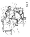
- Fig. 1
- is a perspective view of a seed metering machine;
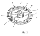
- Fig. 2
- is a perspective view of a drive hub used in the seed metering machine of
Fig. 1 ; - Fig. 3
- is a perspective view of the drive hub of
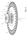
Fig. 2 in with a drive spindle and retention device; - Fig. 4
- is a perspective view of
Fig. 2 and the seek disk ofFig. 1 showing a relative position for assembly; - Fig. 5
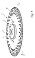
- is a perspective view of the hub of
Fig. 2 and the seed disk ofFig. 1 in the installed position; - Fig. 6
- is a perspective view of the assembled hub of
Fig. 2 and disk ofFig. 1 without the spindle and associated elements taken on lines 6-6 ofFig. 5 ; and - Fig. 7
- is a partial perspective view of the hub of
Fig. 2 and the disk ofFig. 1 showing a portion of the drive spindle assembly and associated elements. - Referring to
Fig. 1 , a seed meter, generally indicated by reference character 10, is incorporated in a seeding machine (not shown). The seeding machine has many additional features such as a main hopper or seed air pump to deliver seed to individual seed meters of which unit 10 is one of multiple units. Details of such an overall system may be found inU.S. Patent 6,758,153 , of common assignment with this invention, the disclosure of which is hereby incorporated in its entirety. The seed meter 10 includes ahousing 12 and aseed hopper 14 which receives an appropriate supply of seeds from a main hopper (not shown).Seed hopper 14 delivers seeds to a chamber in ahousing 16 at the lower portion ofhousing 12. Aseed disk 18 is journaled inhousing 12 and has aseed side 22 exposed tochamber 16 and alower pressure side 24 exposed to a vacuum source for maintaining a pressure differential acrossseed disk 18.Seed disk 18 has a plurality ofseed cells 20 positioned in a circular fashion aroundseed disk 18.Seed cells 20 may take many different forms, but in the illustrated form they are apertures extending throughseed disk 18 to connect theseed side 22 to thelower pressure side 24. It should be understood by those skilled in the art that the pressure levels ofsides -
Seed disk 18 is journaled ondrive spindle 26 which is driven by anappropriate motor 28 through a gear mechanism (not shown) to turn theseed disk 18 in the direction of arrows A. The seeds that have accumulated against the bottom ofseed disk 18 then find their way to the seed cells by virtue of the pressure differential across the seed disk. As the disk turns in a counterclockwise fashion, as shown inFig. 1 , the seeds that are in the seed cells are retained one at a time. The rotation of the disk takes the individual seeds to a segment (not shown) where the pressure differential is locally interrupted so that the seed may be discharged into an appropriate planting mechanism. -
Seed disk 18 is connected to spindle 26 by a hub system generally indicated byreference character 30. It is necessary for the seed disk to be accurately positioned relative to the rotational axis ofspindle 26, both from the standpoint of concentricity and an axial position relative to housing12. In the past, the axial position and concentricity of such drive hubs have been established through a complex series of surfaces in which the run out has to be controlled within limits. Furthermore, since the drive hub transmits torque between thespindle 26 and theseed disk 18 provisions must be made for adequate torque transmittal. - As shown particularly in
Fig. 2 , thehub 30 has aflange 32 with an outercircumferential portion 34 that retains and supports a flexible annular sleeve, to be later described. Inboard of the outer circumferential section is aconical section 36 manufactured to be concentric with a rotational axis A of thehub 30. Thehub 30 has a center throughhole 38 which is threaded to receive the end of thedrive spindle 26. The threadedhole 38 is retained within anannular section 40 having a plurality ofnotches 42 for an adjustment purpose, to be described later. Integral with theelement 40, are a pair of radially extendingpaddles 44. Although a pair ofpaddles 44 is illustrated, it should be apparent to those skilled in the art that any number of paddles may be utilized. -
Fig. 3 shows thehub 30 threaded onto the threadedend 46 of thespindle 26. A retainingcollar 48 is threaded to theend 50 ofspindle 26.End collar 48 is appropriately affixed tospindle 26 and acts as a stop for aspring 52, herein shown as a coil spring. The other end ofspring 52 acts on a base wall (not shown) of aretention element 54 having acentral hub 56 and a pair of radially extendingtabs 58 which approximate in dimension thepaddles 44. Thespring 52 is retained within arecess 60 ofhub 56. The resulting combination causes theretention element 54 to be yieldably urged towards theflange 32. The axial position offlange 32 and therefore theconical surface 36, relative tospindle 26, is set by the degree to whichhub 30 is threaded over the threadedsection 46. The threadedsection 46 has a radial through passage (not shown) which receives a spring loadedkey element 62 extending throughrecesses 42 to fix the relative threaded position ofhub 30 ondrive spindle 26. -
Fig. 4 shows the interaction between thehub system 30 and theseed disk 18.Seed disk 18 has an innercylindrical hub section 64 extending from theseed disk 18 towards thehub 30.Cylindrical section 64 has aninner end diameter 66 controlled to a given tolerance level with respect to the rotational axis A of the assembly. The circular edge of the end ofdiameter 66 is adapted to abut theconical surface 36 ofhub 30 so that the two elements are concentric with respect to one another.Seed disk 18 also has acentral opening 68 for accommodating thehub system 30 and a pair ofradial slots 70 adapted to receivepaddles 44. -
Figs. 4 ,5 and6 show thehub assembly 30 without thespindle 26 and associated elements in order to more fully describe the invention. As shown inFig. 5 , thehub 30 is seated againstseed disk 18 andFig. 6 shows theopposite side 24 ofseed disk 18. To further facilitate the explanation of the invention, the retainingelement 54 is omitted. It can be seen that thepaddles 44 extend through therecesses 70 to theside 24 ofseed disk 18. In order to ensure that theretention assembly 54 holds or retains seed disk against the hub 30 a pair oframps 72 extend through approximately little more than 90° arc.Ramps 72 each start out at a level at anend 74 that is approximately at the axial height ofpaddles 44 and extend upward todetents 76 at an elevated level to ensure that theretention element 54 remains in place. -
Fig. 7 shows a partial view ofFig. 6 but with thespindle 26 andretention element 54 in place. It can be seen that after thehub 30 is inserted throughseed disk 18 thetabs 58 clear the entry point oframps 72 so that thetabs 58 can be rotated clockwise as shown by arrow B inFig. 7 so that thetabs 58 are received and retained indetents 76. In this position the bottoms oftabs 58 act against theseed disk 18 to urge it againsthub 30 by virtue of thespring element 52. Thus, the concentricity of the seed disk relative to the spindle is defined by theconical surface 36 and thecylindrical edge 66. Torque is transmitted between thehub 30 and theseed disk 18 throughpaddles 44 which interact with the walls ofslots 70. Thus, the torque transmission is provided in a parallel path to the concentricity position of the assembly relative to thespindle 26. - The axial position of the seed disk of the
hub 30, and thereforeseed disk 18 relative to spindle 26 andhousing 12, is adjusted by pulling out thepin 62 and threading thehub 30 in a clockwise or counterclockwise direction as needed to obtain the axial position. Once this established thepin 62 is inserted through thenearest slot 42 through the radial passage in the threadedsection 46 ofspindle 26. - In order to provide a seal between the
hub 30 andseed disk 18, a conical, resilient, seal element 80 (shown partially cut away) is affixed to flange 34 ofhub 30.Seal 80 ensures that an adequate pressure differential is maintained across theseed disk 18 and that no significant leakage passes through the interconnected hub and seed disk. - Thus it is seen that the concentricity of the hub relative to the spindle is determined by several key dimensions rather than a multiplicity of dimensions as done in the past
- Having described the preferred embodiment, it will become apparent that various modifications can be made without departing from the scope of the invention as defined in the accompanying claims.
Claims (20)
- A drive hub (30) for connecting a drive spindle (26) to a seed disk (18), said drive hub (30) comprising: a cylindrical element (64) connected to one of the seed disk (18) and drive spindle (26), said cylindrical element (64) having a circular edge at one end thereof, characterized in that the drive hub (30) comprising a conical element (36) connected to the other of the seed disk (18) and drive spindle (26), said conical element (36) being received in the said one end of said cylindrical element (64) to pilot the conical element (36) and cylindrical element (64) relative to each other, said conical element (36) and said cylindrical element (64) inter-fitting to transmit torque therebetween.
- A drive hub (30) as claimed in claim 1, wherein said torque transmission between said cylindrical element (64) and said conical element (36) is independent of the pilot therebetween.
- A drive hub (30) as claimed in claim 1 or 2, wherein said torque transmission is provided by at least one paddle element (44) extending radially with respect to one of said conical element (36) and said cylindrical element (64), the other of said conical element (36) and said cylindrical element (64) having a corresponding radial slot (70) for receiving said paddle element (44).
- A drive hub (30) as claimed in one of the claims 1 to 3, wherein said cylindrical element (64) is integral with said seed disk (18).
- A drive hub (30) as claimed in one of the claims 1 to 4, wherein said conical element (36) and said cylindrical element (64) are axially fixed relative to one another.
- A drive hub (30) as claimed in one of the claims 3 to 5, wherein the element (36, 64) having said paddle (44) has a tab (58) in line with said paddle (44) for insertion through said slot (70) to the opposite side of the other of said conical element (36) and said cylindrical element (64) for pivotal rotation to restrain said cylindrical element (64) relative to said conical element (36).
- A drive hub (30) as claimed in claim 6, wherein said tab (58) urges said cylindrical element (64) and said conical element (36) towards one another.
- A drive hub (30) as claimed in one of the claims 1 to 7, further comprising a flexible seal (80) on one of said conical element (36) and said cylindrical element (64) for pressing against said seed disk (18).
- A drive hub (30) as claimed in one of the claims 1 to 8, wherein said conical element (36) has a central opening (38) and has internal threads for engaging external threads on said drive spindle (26).
- A seed metering assembly (10) comprising: a seed metering disk (18) substantially circular and rotating about a central axis; a drive spindle (26) for said metering disk (18), said drive spindle (26) being rotatable about an axis; and a drive hub (30) for connecting said drive spindle (26) to said seed disk (18) comprising a cylindrical element (64) connected to one of the seed disk (18) and drive spindle (26), said cylindrical element (64) having a circular edge at one end thereof, and a conical element (36) connected to the other of the seed disk (18) and drive spindle (26), said conical element (36) being received in the said one end of said cylindrical element (64), to pilot the conical element (36) and cylindrical element (64) relative to each other, said conical element (36) and said cylindrical element (64) inter-fitting to transmit torque therebetween.
- A seed metering disk assembly (10) as claimed in claim 10, wherein the torque transmission is independent of said pilot interaction.
- A seed metering disk assembly (10) as claimed in claim 10 or 11, wherein one of said conical element (36) and said cylindrical element (64) has at least one paddle (44) extending radially relative thereto, the other of said conical element (36) and said cylindrical element (64) having at least one radial slot (70) receiving said paddle (44) for transmitting torque.
- A seed metering disk assembly (10) as claimed in one of the claims 10 to 12, wherein one of said conical element (36) and said cylindrical element (64) is integral with said seed disk (18).
- A seed metering disk assembly (10) as claimed in one of the claims 10 to 13, wherein said conical element (36) and said cylindrical element (64) are restrained axially with respect to each other.
- A seed metering disk assembly (10) as claimed in one of the claims 12 to 14, wherein the element (36, 64) having said paddle (44) has a tab (58) extending radially therefrom and inline with said paddle (44), said tab (58) being insertable through said radial slot (70) and pivotal to restrain said cylindrical element (64) relative to said conical element (36).
- A seed metering disk assembly (10) as claimed in claim 15, wherein the element receiving said tab (58) has a ramp (72) which is traversed by said tab (58) to an elevated position for restraining of said conical element (36) and said cylindrical element (64) relative to one another.
- A seed metering disk assembly (10) as claimed in claim 15 or 16, wherein the element (36, 64) receiving said tab (58) has a detent (76) in an elevated position for retaining said tab (58).
- A seed metering disk assembly as claimed in one of the claims 15 to 17, wherein said tab (58) is yieldably urged towards said detent (76).
- A seed metering disk assembly as claimed in one of the claims 10 to 18, wherein said drive spindle (26) has a flange (48) retaining a substantially coaxial spring (52), said spring (52) urging said tab (58) toward said detent (76).
- A seed metering disk assembly (10) as claimed in one of the claims 10 to 19, wherein said cylindrical element (64) is integral with said seed disk (18) and said conical element (36) has a yieldable flexible conical seal element (80) for abutting and sealing against said seed disk (18).
Applications Claiming Priority (1)
| Application Number | Priority Date | Filing Date | Title |
|---|---|---|---|
| US11/564,906 US7341010B1 (en) | 2006-11-30 | 2006-11-30 | Seed disk drive hub |
Publications (2)
| Publication Number | Publication Date |
|---|---|
| EP1927276A1 true EP1927276A1 (en) | 2008-06-04 |
| EP1927276B1 EP1927276B1 (en) | 2010-05-26 |
Family
ID=39111011
Family Applications (1)
| Application Number | Title | Priority Date | Filing Date |
|---|---|---|---|
| EP07121443A Active EP1927276B1 (en) | 2006-11-30 | 2007-11-23 | Drive Hub and Seed Metering Disk with such |
Country Status (12)
| Country | Link |
|---|---|
| US (1) | US7341010B1 (en) |
| EP (1) | EP1927276B1 (en) |
| AR (1) | AR064599A1 (en) |
| AU (1) | AU2007231832B2 (en) |
| BR (1) | BRPI0704601B1 (en) |
| CA (1) | CA2606281A1 (en) |
| DE (1) | DE602007006742D1 (en) |
| ES (1) | ES2342985T3 (en) |
| MX (1) | MX2007014821A (en) |
| RU (1) | RU2473199C2 (en) |
| UA (1) | UA94906C2 (en) |
| ZA (1) | ZA200710372B (en) |
Cited By (2)
| Publication number | Priority date | Publication date | Assignee | Title |
|---|---|---|---|---|
| CN113950908A (en) * | 2021-11-08 | 2022-01-21 | 黑龙江省农业机械工程科学研究院 | An electric drive double seed metering device |
| WO2023154696A1 (en) * | 2022-02-08 | 2023-08-17 | Kinze Manufacturing, Inc. | Singulator insert for 3d singulation and seed orientation |
Families Citing this family (9)
| Publication number | Priority date | Publication date | Assignee | Title |
|---|---|---|---|---|
| US8375873B2 (en) * | 2009-06-02 | 2013-02-19 | Great Plains Manufacturing, Inc. | Seed metering device for agricultural seeder |
| IT1399486B1 (en) * | 2010-03-31 | 2013-04-19 | Ima Safe S R L | IMPROVED WITH DISTRIBUTOR UNITS AND PERFECTED DISTRIBUTOR UNIT |
| CN101999267B (en) * | 2010-10-15 | 2012-07-25 | 沈阿庆 | Multifunctional bunch planter |
| US9282692B2 (en) | 2012-10-23 | 2016-03-15 | Kinze Manufacturing, Inc. | Air seed meter with internal drive |
| TWI680040B (en) * | 2014-09-17 | 2019-12-21 | 美商法伯沃克斯分解股份有限公司 | Multi-component robotic hub mounting plate to facilitate hub removal |
| EP3370497A1 (en) | 2015-11-06 | 2018-09-12 | Kinze Manufacturing, Inc. | Multiple agricultural product application method and systems |
| USD847868S1 (en) | 2017-07-28 | 2019-05-07 | Kinze Manufacturing, Inc. | Seed disk with integrated hub |
| CN114145106B (en) * | 2021-10-18 | 2023-07-07 | 山东省农业科学院作物研究所 | Seeding disc with even seeding function |
| FR3145666B1 (en) * | 2023-02-10 | 2025-03-28 | Ribouleau Monosem | Dosing unit for a seeding machine. |
Citations (4)
| Publication number | Priority date | Publication date | Assignee | Title |
|---|---|---|---|---|
| EP0140699A2 (en) * | 1983-10-31 | 1985-05-08 | Deere & Company | Disk mounting arrangement |
| US4664290A (en) * | 1985-02-25 | 1987-05-12 | Deere & Company | Method and apparatus for precise positioning of a seed disk in a seed meter |
| US5170909A (en) * | 1983-10-31 | 1992-12-15 | Deere & Company | Vacuum seed meter |
| US20050204972A1 (en) * | 2003-12-29 | 2005-09-22 | Kinze Manufacturing, Inc. (Iowa Corporation) | Air seed meter |
Family Cites Families (6)
| Publication number | Priority date | Publication date | Assignee | Title |
|---|---|---|---|---|
| US3732896A (en) * | 1971-04-26 | 1973-05-15 | Vyzk Ustav Bavlnarsky | Method of and apparatus for filling the shuttles with weft in progressive shed weaving looms |
| SU576983A1 (en) * | 1976-04-04 | 1977-10-25 | Ворошиловградский Сельскохозяйственный Институт | Sowing apparatus |
| US4294408A (en) * | 1980-05-08 | 1981-10-13 | Graco Inc. | In centrifugal spray guns |
| US4613056A (en) * | 1983-10-31 | 1986-09-23 | Deere & Company | Seed meter having cleanout and seed sealing member |
| SU1175650A1 (en) * | 1984-03-21 | 1985-08-30 | Предприятие П/Я Р-6654 | Shaft-to-hub taper joint |
| US6758153B1 (en) | 2003-08-11 | 2004-07-06 | Deere & Company | Easily adjustable double eliminator |
-
2006
- 2006-11-30 US US11/564,906 patent/US7341010B1/en active Active
-
2007
- 2007-10-11 CA CA002606281A patent/CA2606281A1/en not_active Abandoned
- 2007-11-02 AU AU2007231832A patent/AU2007231832B2/en active Active
- 2007-11-21 UA UAA200712903A patent/UA94906C2/en unknown
- 2007-11-23 BR BRPI0704601-4A patent/BRPI0704601B1/en active IP Right Grant
- 2007-11-23 ES ES07121443T patent/ES2342985T3/en active Active
- 2007-11-23 DE DE602007006742T patent/DE602007006742D1/en active Active
- 2007-11-23 EP EP07121443A patent/EP1927276B1/en active Active
- 2007-11-26 AR ARP070105225A patent/AR064599A1/en active IP Right Grant
- 2007-11-26 MX MX2007014821A patent/MX2007014821A/en active IP Right Grant
- 2007-11-29 ZA ZA200710372A patent/ZA200710372B/en unknown
- 2007-11-29 RU RU2007144483/13A patent/RU2473199C2/en active
Patent Citations (4)
| Publication number | Priority date | Publication date | Assignee | Title |
|---|---|---|---|---|
| EP0140699A2 (en) * | 1983-10-31 | 1985-05-08 | Deere & Company | Disk mounting arrangement |
| US5170909A (en) * | 1983-10-31 | 1992-12-15 | Deere & Company | Vacuum seed meter |
| US4664290A (en) * | 1985-02-25 | 1987-05-12 | Deere & Company | Method and apparatus for precise positioning of a seed disk in a seed meter |
| US20050204972A1 (en) * | 2003-12-29 | 2005-09-22 | Kinze Manufacturing, Inc. (Iowa Corporation) | Air seed meter |
Cited By (2)
| Publication number | Priority date | Publication date | Assignee | Title |
|---|---|---|---|---|
| CN113950908A (en) * | 2021-11-08 | 2022-01-21 | 黑龙江省农业机械工程科学研究院 | An electric drive double seed metering device |
| WO2023154696A1 (en) * | 2022-02-08 | 2023-08-17 | Kinze Manufacturing, Inc. | Singulator insert for 3d singulation and seed orientation |
Also Published As
| Publication number | Publication date |
|---|---|
| US7341010B1 (en) | 2008-03-11 |
| DE602007006742D1 (en) | 2010-07-08 |
| RU2007144483A (en) | 2009-06-10 |
| BRPI0704601B1 (en) | 2017-10-17 |
| AU2007231832B2 (en) | 2012-09-13 |
| ES2342985T3 (en) | 2010-07-20 |
| CA2606281A1 (en) | 2008-05-30 |
| RU2473199C2 (en) | 2013-01-27 |
| BRPI0704601A (en) | 2008-07-15 |
| AU2007231832A1 (en) | 2008-06-19 |
| UA94906C2 (en) | 2011-06-25 |
| MX2007014821A (en) | 2009-02-12 |
| EP1927276B1 (en) | 2010-05-26 |
| ZA200710372B (en) | 2009-09-30 |
| AR064599A1 (en) | 2009-04-15 |
Similar Documents
| Publication | Publication Date | Title |
|---|---|---|
| EP1927276B1 (en) | Drive Hub and Seed Metering Disk with such | |
| US7451713B2 (en) | Seed disk for a seed meter | |
| EP2106683B1 (en) | Seeding machine | |
| EP3586585B1 (en) | Seeding system | |
| EP3622793B1 (en) | Seeding system | |
| US11064649B2 (en) | Seeding system | |
| AU2010246522B2 (en) | Volumetric metering system with clutch based sectional shut-off | |
| EP1894458B1 (en) | Seed singulator for a seed metering system in a seeding machine | |
| US10154623B2 (en) | Air seed meter housing with seed path relief | |
| EP3017673B1 (en) | Seed meter assembly, row unit with such and loader for such | |
| EP1917846B1 (en) | Apparatus for setting the position of a singulator arm for a seed metering system and seed metering system and seeding machine with such apparatus | |
| US20200253109A1 (en) | Seed metering disc | |
| SU1753979A1 (en) | Sowing apparatus | |
| US11980121B2 (en) | Agricultural pneumatic meters | |
| WO2025160656A1 (en) | Planter | |
| CN121369020A (en) | Separating device for seed metering mechanism and related seeder |
Legal Events
| Date | Code | Title | Description |
|---|---|---|---|
| PUAI | Public reference made under article 153(3) epc to a published international application that has entered the european phase |
Free format text: ORIGINAL CODE: 0009012 |
|
| AK | Designated contracting states |
Kind code of ref document: A1 Designated state(s): AT BE BG CH CY CZ DE DK EE ES FI FR GB GR HU IE IS IT LI LT LU LV MC MT NL PL PT RO SE SI SK TR |
|
| AX | Request for extension of the european patent |
Extension state: AL BA HR MK RS |
|
| RIN1 | Information on inventor provided before grant (corrected) |
Inventor name: LUXON, GARY D Inventor name: FRIESTAD, MICHAEL E |
|
| 17P | Request for examination filed |
Effective date: 20081204 |
|
| AKX | Designation fees paid |
Designated state(s): DE ES FR HU IT |
|
| GRAP | Despatch of communication of intention to grant a patent |
Free format text: ORIGINAL CODE: EPIDOSNIGR1 |
|
| GRAS | Grant fee paid |
Free format text: ORIGINAL CODE: EPIDOSNIGR3 |
|
| GRAA | (expected) grant |
Free format text: ORIGINAL CODE: 0009210 |
|
| AK | Designated contracting states |
Kind code of ref document: B1 Designated state(s): DE ES FR HU IT |
|
| REF | Corresponds to: |
Ref document number: 602007006742 Country of ref document: DE Date of ref document: 20100708 Kind code of ref document: P |
|
| REG | Reference to a national code |
Ref country code: ES Ref legal event code: FG2A Ref document number: 2342985 Country of ref document: ES Kind code of ref document: T3 |
|
| REG | Reference to a national code |
Ref country code: HU Ref legal event code: AG4A Ref document number: E009181 Country of ref document: HU |
|
| PLBE | No opposition filed within time limit |
Free format text: ORIGINAL CODE: 0009261 |
|
| STAA | Information on the status of an ep patent application or granted ep patent |
Free format text: STATUS: NO OPPOSITION FILED WITHIN TIME LIMIT |
|
| 26N | No opposition filed |
Effective date: 20110301 |
|
| REG | Reference to a national code |
Ref country code: DE Ref legal event code: R097 Ref document number: 602007006742 Country of ref document: DE Effective date: 20110228 |
|
| REG | Reference to a national code |
Ref country code: DE Ref legal event code: R119 Ref document number: 602007006742 Country of ref document: DE Effective date: 20110601 Ref country code: DE Ref legal event code: R119 Ref document number: 602007006742 Country of ref document: DE Effective date: 20110531 |
|
| PG25 | Lapsed in a contracting state [announced via postgrant information from national office to epo] |
Ref country code: IT Free format text: LAPSE BECAUSE OF NON-PAYMENT OF DUE FEES Effective date: 20101123 |
|
| PG25 | Lapsed in a contracting state [announced via postgrant information from national office to epo] |
Ref country code: DE Free format text: LAPSE BECAUSE OF NON-PAYMENT OF DUE FEES Effective date: 20110531 |
|
| PGFP | Annual fee paid to national office [announced via postgrant information from national office to epo] |
Ref country code: IT Payment date: 20131125 Year of fee payment: 7 |
|
| PGFP | Annual fee paid to national office [announced via postgrant information from national office to epo] |
Ref country code: HU Payment date: 20141107 Year of fee payment: 8 |
|
| REG | Reference to a national code |
Ref country code: FR Ref legal event code: PLFP Year of fee payment: 9 |
|
| PG25 | Lapsed in a contracting state [announced via postgrant information from national office to epo] |
Ref country code: IT Free format text: LAPSE BECAUSE OF NON-PAYMENT OF DUE FEES Effective date: 20141123 |
|
| PG25 | Lapsed in a contracting state [announced via postgrant information from national office to epo] |
Ref country code: HU Free format text: LAPSE BECAUSE OF NON-PAYMENT OF DUE FEES Effective date: 20151124 |
|
| REG | Reference to a national code |
Ref country code: FR Ref legal event code: PLFP Year of fee payment: 10 |
|
| REG | Reference to a national code |
Ref country code: FR Ref legal event code: PLFP Year of fee payment: 11 |
|
| PGFP | Annual fee paid to national office [announced via postgrant information from national office to epo] |
Ref country code: FR Payment date: 20251125 Year of fee payment: 19 |
|
| PGFP | Annual fee paid to national office [announced via postgrant information from national office to epo] |
Ref country code: ES Payment date: 20251201 Year of fee payment: 19 |