EP1926274A1 - Transmission apparatus and transmission method - Google Patents
Transmission apparatus and transmission method Download PDFInfo
- Publication number
- EP1926274A1 EP1926274A1 EP07022684A EP07022684A EP1926274A1 EP 1926274 A1 EP1926274 A1 EP 1926274A1 EP 07022684 A EP07022684 A EP 07022684A EP 07022684 A EP07022684 A EP 07022684A EP 1926274 A1 EP1926274 A1 EP 1926274A1
- Authority
- EP
- European Patent Office
- Prior art keywords
- bit sequence
- layer
- radio resource
- information source
- layer coding
- Prior art date
- Legal status (The legal status is an assumption and is not a legal conclusion. Google has not performed a legal analysis and makes no representation as to the accuracy of the status listed.)
- Withdrawn
Links
Images




Classifications
-
- H—ELECTRICITY
- H04—ELECTRIC COMMUNICATION TECHNIQUE
- H04L—TRANSMISSION OF DIGITAL INFORMATION, e.g. TELEGRAPHIC COMMUNICATION
- H04L27/00—Modulated-carrier systems
- H04L27/26—Systems using multi-frequency codes
- H04L27/2601—Multicarrier modulation systems
- H04L27/2626—Arrangements specific to the transmitter only
-
- H—ELECTRICITY
- H04—ELECTRIC COMMUNICATION TECHNIQUE
- H04L—TRANSMISSION OF DIGITAL INFORMATION, e.g. TELEGRAPHIC COMMUNICATION
- H04L27/00—Modulated-carrier systems
- H04L27/18—Phase-modulated carrier systems, i.e. using phase-shift keying
- H04L27/183—Multiresolution systems
-
- H—ELECTRICITY
- H04—ELECTRIC COMMUNICATION TECHNIQUE
- H04L—TRANSMISSION OF DIGITAL INFORMATION, e.g. TELEGRAPHIC COMMUNICATION
- H04L27/00—Modulated-carrier systems
- H04L27/26—Systems using multi-frequency codes
- H04L27/2601—Multicarrier modulation systems
- H04L27/2626—Arrangements specific to the transmitter only
- H04L27/2627—Modulators
-
- H—ELECTRICITY
- H04—ELECTRIC COMMUNICATION TECHNIQUE
- H04L—TRANSMISSION OF DIGITAL INFORMATION, e.g. TELEGRAPHIC COMMUNICATION
- H04L5/00—Arrangements affording multiple use of the transmission path
- H04L5/0001—Arrangements for dividing the transmission path
- H04L5/0014—Three-dimensional division
- H04L5/0016—Time-frequency-code
-
- H—ELECTRICITY
- H04—ELECTRIC COMMUNICATION TECHNIQUE
- H04L—TRANSMISSION OF DIGITAL INFORMATION, e.g. TELEGRAPHIC COMMUNICATION
- H04L5/00—Arrangements affording multiple use of the transmission path
- H04L5/003—Arrangements for allocating sub-channels of the transmission path
- H04L5/0058—Allocation criteria
- H04L5/0064—Rate requirement of the data, e.g. scalable bandwidth, data priority
Definitions
- the present invention relates to a transmission apparatus and a transmission method employing a layer coding method.
- a layer coding method has been known as a method for efficient and simultaneous transmission of information sources having different priorities.
- the layer coding method is capable of improving transmission efficiency of an information source having a high priority even in an environment with a poor communication state, in the following way.
- a symbol component 1 is assigned a bit sequence which constitutes a high-priority information source
- a symbol component 2 is assigned a bit sequence which constitutes a low-priority information source.
- the symbol component 1 is assumed to be received with a higher reception quality in a reception apparatus, while the symbol component 2 is assumed to be received with a lower reception quality in the reception apparatus.
- the transmission apparatus 20 is configured by applying the layer coding method to the orthogonal frequency division multiplexing (OFDM) method that is one of multi-carrier transmission methods.
- OFDM orthogonal frequency division multiplexing
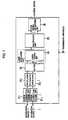
- the transmission apparatus 20 includes a plurality of error correction coding units 21 1 , 21 2 , ..., a plurality of interleavers 22 1 , 22 2 , ..., a buffer 23, a layer modulating unit provided with a layer coding unit 24, a multiplexing unit 25 and an OFDM signal generating unit 26.
- each of the error correction coding units 21 1 , 21 2 , ... perform error correction coding processing for bit sequences constituting the inputted information sources 1, 2, ..., respectively.
- each of the interleavers 22 1 , 22 2 , ... perform interleave processing for the bit sequences outputted from the error correction coding units 21 1 , 21 2 , ..., respectively, after the error correction processing.
- step S203 the buffer 23 stores the bit sequences outputted from the interleavers 22 1 , 22 2 , ..., respectively, after the interleave processing.
- step S204 the layer coding unit 24 performs layer coding processing for the bit sequences extracted from the buffer 23, according to a priority level of each of the information sources 1, 2, ..., that constitute the bit sequences.
- the layer coding unit 24 is configured to perform layer coding processing for a symbol component B1 (1, 1) is assigned a bit sequence which constitutes a high-priority information source 1, and where a symbol component B2 (1, -1) is assigned a bit sequence which constitutes a low-priority information source 2.
- the symbol component B1 (1, 1) is assumed to be received with a higher reception quality in the reception apparatus and the symbol component B2 (1, -1) is assumed to be received with a lower reception quality in the reception apparatus.
- the modulated signal having performed the layer coding processing is configured of any one of sixteen patterns of symbols with four bits indicated in one symbol.
- the symbol component B1 indicates a coordinate point based on the origin point
- the symbol component B2 indicates a coordinate point based on the point A corresponding to the symbol component B1.
- reception quality of the symbol component B1 in the reception apparatus is assumed to be better than reception quality of the symbol component B2 in the reception apparatus. This is because the symbol component B1 indicates only one coordinate point in one quadrant, while the symbol component B2 can potentially indicate four coordinate points in one quadrant.
- the transmission is enabled by performing the layer coding unit 24 to assign a bit sequence which constitutes a high-priority information source 1 to a symbol component 1 (I component), and to assign a bit sequence which constitutes a low-priority information source 2 to a symbol component 2 (Q component).
- the symbol component 1 (I component) is assumed to be received with a higher reception quality in a reception apparatus, while the symbol component 2 (Q component) is assumed to be received with a lower reception quality in the reception apparatus.
- the modulated signal having performed the layer coding processing is configured of any one of four patterns of symbols with two bits indicated in one symbol.
- the reception quality of I component in the reception apparatus is assumed to be better than that of Q component, since the distance 251 between signal points of I component is longer than the distance 252 between signal points of Q component.
- step S205 the multiplexing unit 25 performs, multiplexing processing (scheduling processing) for the modulated signal having performed the layer coding processing, the modulated signal outputted from the layer coding unit 24.
- the multiplexing unit 25 assigns the modulated signal to a radio resource divided based on a time and a frequency (an orthogonal signal).
- step S206 the OFDM signal generating unit 26 converts the modulated signal assigned to the radio resource into an OFDM signal, and then transmits the OFDM signal.
- any bit sequence constituting the information source 2 is not assigned to a part of a symbol component 2.
- the layer coding unit 24 performs the layer coding processing in which bit sequence constituting information source 2 is not assigned to the symbol component B2 and a bit sequence constituting the information source 1 is assigned only to the symbol component B1.
- the modulated signal having performed the layer coding processing in this case is configured of any one of four patterns of symbols with two bits indicated in one symbol (that is, the modulated signal in this case has two symbol components).
- the layer coding unit 24 performs layer coding processing in which a symbol component 2 (Q component) is not assigned any bit sequence constituting the information source 2, and only a symbol component 1 (I component) is assigned a bit sequence constituting the information source 1.
- the modulated signal having performed the layer coding processing in this case is configured of any one of two patterns of symbols with one bit indicated in one symbol.
- the present invention has been made in view of the above-mentioned problems, and aims to provide a transmission apparatus capable of preventing deterioration in transmission efficiency while making full use of effects of layer coding processing and multiplexing processing (scheduling processing).
- a first aspect of the present invention is summarized as a transmission apparatus: a layer multiplexing unit configured to assign, to a radio resource which is divided based on a time, a frequency and a layer, a bit sequence which constitutes at least one information source to be transmitted, in accordance with a communication state and a priority level of the information source; and a layer coding unit configured to perform a layer coding processing for the bit sequence assigned to the radio resource, wherein the layer multiplexing unit is configured to perform the assignment so that a length of each bit sequence assigned to each radio resource becomes equivalent.
- the problem of deterioration in transmission efficiency can be solved. This is because, the deterioration is caused, a bit sequence is not assigned to a part of a symbol component in the modulated signal having performed the layer coding processing, when a length of each bit sequence differs between information sources having different priority levels.
- the layer coding unit is configured to perform layer coding processing for each bit sequence of the equal length, assigned to the radio resources.
- the layer multiplexing unit may assign, to the each radio resource, the each bit sequence with a length corresponding to a transmittable data length in the each radio resource.
- the problem of deterioration in transmission efficiency can be solved. This is because, the deterioration is caused, a bit sequence constituting the information source is not assigned to a part of a symbol component in the modulated signal having performed the layer coding processing, when the transmittable data length of each radio resource is longer than a length of a bit sequence constituting each of the information sources.
- the layer multiplexing unit is configured to assign, to the radio resource, each bit sequence with a length corresponding to a transmittable data length of the each radio resource.
- a second aspect of the present invention is summarized as a transmission method including: assigning, to a radio resource which is divided based on a time, a frequency and a layer, a bit sequence which constitutes at least one information source to be transmitted, in accordance with a communication state and a priority level of the information source; and performing a layer coding processing for the bit sequence assigned to the radio resource, wherein in the step of assigning, so that a length of each bit sequence assigned to each radio resource becomes equivalent.
- the transmission apparatus 10 according to the first embodiment of the present invention is configured, as similar to the transmission apparatus 20 shown in Fig. 1 above, by applying the layer coding method to the OFDM method that is one of multi-carrier transmission methods.
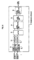
- the transmission apparatus 10 includes a plurality of error correction coding units 11 1 , 11 2 , ..., a plurality of interleavers 12 1 , 12 2 , ..., a buffer 13, a layer multiplexing unit 14, a layer coding unit 15, and an OFDM signal generating unit 16.
- the error correction coding units 11 1 , 11 2 , ... are configured to perform error correction coding processing for each bit sequence constituting a corresponding one of the inputted information sources 1, 2, ...
- the interleavers 12 1 , 12 2 , ... are configured to perform interleave processing for each bit sequence outputted from the error correction coding units 11 1 , 11 2 , ... after error correction processing.
- the buffer 13 is configured to store the bit sequences outputted from the interleavers 12 1 , 12 2 , ..., after the interleave processing.
- the layer multiplexing unit 14 is configured to assign, to a radio resource, a bit sequence which constitutes at least one information source 1, 2, ... to be transmitted, in accordance with a communication state and a priority level of the information sources.
- the radio resources are divided based on a time, a frequency (orthogonal frequency and sub-carrier) and a layer.
- the layer multiplexing unit 14 is configured to perform multiplexing processing (scheduling processing) for bit sequences extracted from the buffer 13.
- the layer multiplexing unit 14 performs the multiplexing processing (scheduling processing) for the bit sequences extracted from the buffer 13 after determining the following. Specifically, the layer multiplexing unit 14 determines, in accordance with the priority level of the information source corresponding to each of the extracted bit sequences, whether to assign the extracted bit sequence to a radio resource B belonging to a high-priority layer, or to a radio resource A belonging to a low-priority layer.
- the layer multiplexing unit 14 is configured to perform assignment so that a length of each bit sequence assigned to the each radio resource A and B becomes equivalent to one another.
- the layer multiplexing unit 14 assigns a bit sequence constituting the information source 1 to the radio resource A, and assigns a bit sequence constituting the information source 2 and a bit sequence constituting the information source 3 to the radio resource B. In this way, the layer multiplexing unit 14 performs multiplexing processing (scheduling processing) by assigning so that a length of each bit sequence assigned to the each radio resource A and B becomes equivalent (see Fig. 8A).
- the layer multiplexing unit 14 may be configured to assign, to the radio resources A and B, each bit sequence with a length corresponding to a transmittable data length in the each radio resources A and B, respectively.
- the layer multiplexing unit 14 may perform multiplexing processing (scheduling processing) by assigning a bit sequence constituting the information source 1 and a bit sequence constituting the information source 4 to the radio resource A, and assigning a bit sequence constituting the information source 2 and a bit sequence constituting the information source 5 to the radio resource B.
- the radio resources A and B are assigned each bit sequence with length corresponding to the each transmittable data length of the each radio resources A and B, respectively (see Fig. 8B).
- the layer coding unit 15 is configured to perform a layer coding processing for the bit sequence assigned to each of the radio resources A and B outputted from the layer multiplexing unit 14.
- the layer coding unit 15 is configured to perform the layer coding processing by the above-mentioned methods shown in Figs. 3 and 4.
- multiplexing processing can be performed so that bit sequences with the equal length are assigned to the radio resources A and B, even when a length of a bit sequence constituting the information source 1 is longer than a length of a bit sequence constituting the information source 2.
- the layer multiplexing unit 14 assigns a bit sequence constituting the information source 1 to the radio resource A, and assigns a bit sequence constituting the information source 2 and a bit sequence constituting the information source 3 to the radio resource B.
- the transmission apparatus 10 can prevent from occurring the state where a bit sequence is not assigned to the symbol component 2 in the modulated signal having performed the layer coding processing.
- multiplexing processing can be performed the assignment, to each of the radio resources A and B, each bit sequence with a length corresponding to the transmittable data length of each of the radio resources A and B, even when the transmittable data length of each of the radio resources A and B is longer than a bit sequence constituting the information source 1 and a bit sequence constituting the information source 2.
- the layer multiplexing unit 14 assigns a bit sequence constituting the information source 1 and a bit sequence constituting the information sources 4 to the radio resource A, and assigns a bit sequence constituting the information source 2 and a bit sequence constituting the information source 5 to the radio resource B.
- the transmission apparatus 10 can prevent from occurring the state where a bit sequence is not assigned to the symbol components 1 and 2 in the modulated signal having performed the layer coding processing.
- the OFDM signal generating unit 16 is configured to convert the modulated signal assigned to each of the radio resources A and B into an OFDM signal, and then to transmit the signals.
- the layer multiplexing unit 14 assigns, to the radio resources, a bit sequence constituting at least one information source 1, 2, ... to be transmitted, in accordance with a communication state and a priority level of information source 1, 2, ..., extracted from the buffer 13.
- the radio resources are divided by a time, a frequency (orthogonal frequency and sub-carrier), and a layer.
- step S105 the layer coding unit 15 performs layer coding processing for each bit sequence assigned to each of the radio resources A and B, outputted from the layer multiplexing unit 14.
- step s106 the OFDM signal generating unit 16 converts the modulated signal assigned to each radio resource into an OFDM signal, and then transmits the OFDM signals.
- the problem of deterioration in transmission efficiency can be solved. This is because, the deterioration is caused, a bit sequence is not assigned to a part of the symbol component B2 in the modulated signal having performed the layer coding processing, when the lengths of bit sequences differ between information sources 1 and 2 having different priority levels (that is, when a length of a bit sequence constituting the information source 1 is longer than a length of a bit sequence constituting the information source 2) .
- the layer coding unit 15 of the transmission apparatus 10 is configured to perform layer coding processing for bit sequences of the equal length, assigned to the radio resources A and B.
- the problem of deterioration in transmission efficiency can be solved. This is because, the deterioration is caused, bit sequences constituting the information sources 1 and 2 are not assigned to a part of each of symbol components B1 and B2 in the modulated signal having performed the layer coding processing, when the transmittable data length of the radio resources A and B is longer than the lengths of bit sequences constituting the information sources 1 and 2.
- the layer multiplexing unit 14 of the transmission apparatus 10 is configured to assign, to each radio resource A and B, each bit sequence with a length corresponding to the transmittable data length of each of the radio resources A and B.
Landscapes
- Engineering & Computer Science (AREA)
- Signal Processing (AREA)
- Computer Networks & Wireless Communication (AREA)
- Mobile Radio Communication Systems (AREA)
- Detection And Prevention Of Errors In Transmission (AREA)
- Transmitters (AREA)
Abstract
Description
- This application is based upon and claims the benefit of priority from the prior
Japanese Patent Applications No. 2006-317486 filed on November 24, 2006 - The present invention relates to a transmission apparatus and a transmission method employing a layer coding method.
- Conventionally, a layer coding method has been known as a method for efficient and simultaneous transmission of information sources having different priorities.
- The layer coding method is capable of improving transmission efficiency of an information source having a high priority even in an environment with a poor communication state, in the following way. In the layer coding method, a
symbol component 1 is assigned a bit sequence which constitutes a high-priority information source, and asymbol component 2 is assigned a bit sequence which constitutes a low-priority information source. Here, thesymbol component 1 is assumed to be received with a higher reception quality in a reception apparatus, while thesymbol component 2 is assumed to be received with a lower reception quality in the reception apparatus. - With reference to Figs. 1 to 4, an explanation will be given for a conventional transmission apparatus 20 employing the layer coding method.
- The transmission apparatus 20 is configured by applying the layer coding method to the orthogonal frequency division multiplexing (OFDM) method that is one of multi-carrier transmission methods.
- As shown in Fig. 1, the transmission apparatus 20 includes a plurality of error correction coding units 211, 212, ..., a plurality of interleavers 221, 222, ..., a
buffer 23, a layer modulating unit provided with alayer coding unit 24, amultiplexing unit 25 and an OFDMsignal generating unit 26. - With reference to Fig. 2, an explanation will be given for operations of the conventional transmission apparatus 20 employing the layer coding method
- As shown in Fig. 2, in step S201, each of the error correction coding units 211, 212, ..., perform error correction coding processing for bit sequences constituting the inputted
information sources - In step S202, each of the interleavers 221, 222, ..., perform interleave processing for the bit sequences outputted from the error correction coding units 211, 212, ..., respectively, after the error correction processing.
- In step S203, the
buffer 23 stores the bit sequences outputted from the interleavers 221, 222, ..., respectively, after the interleave processing. - In step S204, the
layer coding unit 24 performs layer coding processing for the bit sequences extracted from thebuffer 23, according to a priority level of each of theinformation sources - For example, as shown in Fig. 3, the
layer coding unit 24 is configured to perform layer coding processing for a symbol component B1 (1, 1) is assigned a bit sequence which constitutes a high-priority information source 1, and where a symbol component B2 (1, -1) is assigned a bit sequence which constitutes a low-priority information source 2. Here, the symbol component B1 (1, 1) is assumed to be received with a higher reception quality in the reception apparatus and the symbol component B2 (1, -1) is assumed to be received with a lower reception quality in the reception apparatus. - Note that in the example shown in Fig. 3, the modulated signal having performed the layer coding processing is configured of any one of sixteen patterns of symbols with four bits indicated in one symbol.
- Additionally, in the example shown in Fig. 3, the symbol component B1 indicates a coordinate point based on the origin point, and the symbol component B2 indicates a coordinate point based on the point A corresponding to the symbol component B1.
- Here, in the example shown in Fig. 3, reception quality of the symbol component B1 in the reception apparatus is assumed to be better than reception quality of the symbol component B2 in the reception apparatus. This is because the symbol component B1 indicates only one coordinate point in one quadrant, while the symbol component B2 can potentially indicate four coordinate points in one quadrant.
- Moreover, in
Japanese Patent Publication No.2000-31944 information source 1 even in a poor communication state. Specifically, the transmission is enabled by performing thelayer coding unit 24 to assign a bit sequence which constitutes a high-priority information source 1 to a symbol component 1 (I component), and to assign a bit sequence which constitutes a low-priority information source 2 to a symbol component 2 (Q component). Here, the symbol component 1 (I component) is assumed to be received with a higher reception quality in a reception apparatus, while the symbol component 2 (Q component) is assumed to be received with a lower reception quality in the reception apparatus. - Note that, in the example shown in Fig. 4, the modulated signal having performed the layer coding processing is configured of any one of four patterns of symbols with two bits indicated in one symbol.
- Here, the reception quality of I component in the reception apparatus is assumed to be better than that of Q component, since the distance 251 between signal points of I component is longer than the
distance 252 between signal points of Q component. - In step S205, the
multiplexing unit 25 performs, multiplexing processing (scheduling processing) for the modulated signal having performed the layer coding processing, the modulated signal outputted from thelayer coding unit 24. In the multiplexing processing, themultiplexing unit 25 assigns the modulated signal to a radio resource divided based on a time and a frequency (an orthogonal signal). - In step S206, the OFDM
signal generating unit 26 converts the modulated signal assigned to the radio resource into an OFDM signal, and then transmits the OFDM signal. - However, there has been a problem of deterioration in transmission efficiency by using the above-mentioned conventional transmission apparatus 20. This is because, a bit sequence is not assigned to a part of a symbol component in the modulated signal having performed the layer coding processing, when a length of bit sequence differs between a bit sequence of the
information source 1 and a bit sequence of theinformation sources 2. - Here, consider an example case where the length of the bit sequence which constitutes the
information source 1 is longer than the bit sequence which constitutes theinformation source 2, as shown in Fig. 5A. In this example case, any bit sequence constituting theinformation source 2 is not assigned to a part of asymbol component 2. - specifically, if the example shown in Fig. 3 is applied to this example case, the
layer coding unit 24 performs the layer coding processing in which bit sequence constitutinginformation source 2 is not assigned to the symbol component B2 and a bit sequence constituting theinformation source 1 is assigned only to the symbol component B1. - The modulated signal having performed the layer coding processing in this case is configured of any one of four patterns of symbols with two bits indicated in one symbol (that is, the modulated signal in this case has two symbol components).
- Meanwhile, if the example shown in Fig. 4 is applied to the aforementioned example case, the
layer coding unit 24 performs layer coding processing in which a symbol component 2 (Q component) is not assigned any bit sequence constituting theinformation source 2, and only a symbol component 1 (I component) is assigned a bit sequence constituting theinformation source 1. - The modulated signal having performed the layer coding processing in this case is configured of any one of two patterns of symbols with one bit indicated in one symbol.
- Moreover, there has been a problem of deterioration in transmission efficiency by using the above-mentioned conventional transmission apparatus 20. This is because, the deterioration is caused, a bit sequence is not assigned to a part of the each symbol component in the modulated signal having performed the layer coding processing, when a transmittable data length of each radio resource is longer than a length of a bit sequence constituting the
information sources - For example, there has been a problem of deterioration in transmission efficiency when the transmittable data length of each radio resource is longer than the length of the each bit sequence constituting the
information source symbol component information source - Thus, the present invention has been made in view of the above-mentioned problems, and aims to provide a transmission apparatus capable of preventing deterioration in transmission efficiency while making full use of effects of layer coding processing and multiplexing processing (scheduling processing).
- A first aspect of the present invention is summarized as a transmission apparatus: a layer multiplexing unit configured to assign, to a radio resource which is divided based on a time, a frequency and a layer, a bit sequence which constitutes at least one information source to be transmitted, in accordance with a communication state and a priority level of the information source; and a layer coding unit configured to perform a layer coding processing for the bit sequence assigned to the radio resource, wherein the layer multiplexing unit is configured to perform the assignment so that a length of each bit sequence assigned to each radio resource becomes equivalent.
- According to the present invention, the problem of deterioration in transmission efficiency can be solved. This is because, the deterioration is caused, a bit sequence is not assigned to a part of a symbol component in the modulated signal having performed the layer coding processing, when a length of each bit sequence differs between information sources having different priority levels. This problem can be solved since the layer coding unit is configured to perform layer coding processing for each bit sequence of the equal length, assigned to the radio resources.
- In the first aspect of the present invention, the layer multiplexing unit may assign, to the each radio resource, the each bit sequence with a length corresponding to a transmittable data length in the each radio resource.
- According to the present invention, the problem of deterioration in transmission efficiency can be solved. This is because, the deterioration is caused, a bit sequence constituting the information source is not assigned to a part of a symbol component in the modulated signal having performed the layer coding processing, when the transmittable data length of each radio resource is longer than a length of a bit sequence constituting each of the information sources. This problem can be solved since the layer multiplexing unit is configured to assign, to the radio resource, each bit sequence with a length corresponding to a transmittable data length of the each radio resource.
- A second aspect of the present invention is summarized as a transmission method including: assigning, to a radio resource which is divided based on a time, a frequency and a layer, a bit sequence which constitutes at least one information source to be transmitted, in accordance with a communication state and a priority level of the information source; and performing a layer coding processing for the bit sequence assigned to the radio resource, wherein in the step of assigning, so that a length of each bit sequence assigned to each radio resource becomes equivalent.
-
- Fig. 1 is a functional block diagram showing a conventional transmission apparatus.
- Fig. 2 is a flowchart illustrating operations of the conventional transmission apparatus.
- Fig. 3 is a diagram for explaining layer coding processing of a layer coding unit in a conventional transmission apparatus.
- Fig. 4 is a diagram for explaining layer coding processing of a layer coding unit in a conventional transmission apparatus.
- Fig. 5A is a diagram for explaining a problem in the conventional transmission apparatus.
- Fig. 5B is a diagram for explaining a problem in the conventional transmission apparatus.
- Fig. 6 is a functional block diagram showing a transmission apparatus according to a first embodiment of the present invention.
- Fig. 7 is a diagram for explaining multiplexing processing of a layer multiplexing unit of the transmission apparatus according to the first embodiment of the present invention.
- Fig. 8A is a diagram for explaining layer coding processing of a layer coding unit of the transmission apparatus according to the first embodiment of the present invention.
- Fig. 8B is a diagram for explaining layer coding processing of a layer coding unit of the transmission apparatus according to the first embodiment of the present invention.
- Fig. 9 is a flowchart illustrating operations of the transmission apparatus according to the first embodiment of the present invention.
- An explanation will be given for the configuration of a transmission apparatus 10 according to a first embodiment of the present invention with reference to Figs. 6 to 8.
- The transmission apparatus 10 according to the first embodiment of the present invention is configured, as similar to the transmission apparatus 20 shown in Fig. 1 above, by applying the layer coding method to the OFDM method that is one of multi-carrier transmission methods.
- As shown in Fig. 6, the transmission apparatus 10 includes a plurality of error correction coding units 111, 112, ..., a plurality of interleavers 121, 122, ..., a
buffer 13, alayer multiplexing unit 14, alayer coding unit 15, and an OFDMsignal generating unit 16. - The error correction coding units 111, 112, ... are configured to perform error correction coding processing for each bit sequence constituting a corresponding one of the inputted
information sources - The interleavers 121, 122, ... are configured to perform interleave processing for each bit sequence outputted from the error correction coding units 111, 112, ... after error correction processing.
- The
buffer 13 is configured to store the bit sequences outputted from the interleavers 121, 122, ..., after the interleave processing. - The
layer multiplexing unit 14 is configured to assign, to a radio resource, a bit sequence which constitutes at least oneinformation source - In other words, the
layer multiplexing unit 14 is configured to perform multiplexing processing (scheduling processing) for bit sequences extracted from thebuffer 13. - For example, as shown in Fig. 7, the
layer multiplexing unit 14 performs the multiplexing processing (scheduling processing) for the bit sequences extracted from thebuffer 13 after determining the following. Specifically, thelayer multiplexing unit 14 determines, in accordance with the priority level of the information source corresponding to each of the extracted bit sequences, whether to assign the extracted bit sequence to a radio resource B belonging to a high-priority layer, or to a radio resource A belonging to a low-priority layer. - In addition, the
layer multiplexing unit 14 is configured to perform assignment so that a length of each bit sequence assigned to the each radio resource A and B becomes equivalent to one another. - For example, the
layer multiplexing unit 14 assigns a bit sequence constituting theinformation source 1 to the radio resource A, and assigns a bit sequence constituting theinformation source 2 and a bit sequence constituting theinformation source 3 to the radio resource B. In this way, thelayer multiplexing unit 14 performs multiplexing processing (scheduling processing) by assigning so that a length of each bit sequence assigned to the each radio resource A and B becomes equivalent (see Fig. 8A). - Additionally, the
layer multiplexing unit 14 may be configured to assign, to the radio resources A and B, each bit sequence with a length corresponding to a transmittable data length in the each radio resources A and B, respectively. - For example, the
layer multiplexing unit 14 may perform multiplexing processing (scheduling processing) by assigning a bit sequence constituting theinformation source 1 and a bit sequence constituting theinformation source 4 to the radio resource A, and assigning a bit sequence constituting theinformation source 2 and a bit sequence constituting theinformation source 5 to the radio resource B. Hence, the radio resources A and B are assigned each bit sequence with length corresponding to the each transmittable data length of the each radio resources A and B, respectively (see Fig. 8B). - The
layer coding unit 15 is configured to perform a layer coding processing for the bit sequence assigned to each of the radio resources A and B outputted from thelayer multiplexing unit 14. - For example, the
layer coding unit 15 is configured to perform the layer coding processing by the above-mentioned methods shown in Figs. 3 and 4. - Here, according to the transmission apparatus 10 of the present invention, multiplexing processing (scheduling processing) can be performed so that bit sequences with the equal length are assigned to the radio resources A and B, even when a length of a bit sequence constituting the
information source 1 is longer than a length of a bit sequence constituting theinformation source 2. This is because, as mentioned above, thelayer multiplexing unit 14 assigns a bit sequence constituting theinformation source 1 to the radio resource A, and assigns a bit sequence constituting theinformation source 2 and a bit sequence constituting theinformation source 3 to the radio resource B. Hence, as shown in Fig. 8A, the transmission apparatus 10 can prevent from occurring the state where a bit sequence is not assigned to thesymbol component 2 in the modulated signal having performed the layer coding processing. - Moreover, according to the transmission apparatus 10 of the present invention, multiplexing processing (scheduling processing) can be performed the assignment, to each of the radio resources A and B, each bit sequence with a length corresponding to the transmittable data length of each of the radio resources A and B, even when the transmittable data length of each of the radio resources A and B is longer than a bit sequence constituting the
information source 1 and a bit sequence constituting theinformation source 2. This is because, as mentioned above, thelayer multiplexing unit 14 assigns a bit sequence constituting theinformation source 1 and a bit sequence constituting theinformation sources 4 to the radio resource A, and assigns a bit sequence constituting theinformation source 2 and a bit sequence constituting theinformation source 5 to the radio resource B. Hence, as shown in Fig. 8B, the transmission apparatus 10 can prevent from occurring the state where a bit sequence is not assigned to thesymbol components - The OFDM
signal generating unit 16 is configured to convert the modulated signal assigned to each of the radio resources A and B into an OFDM signal, and then to transmit the signals. - An explanation will be given for operations of the transmission apparatus 10 according to the first embodiment of the present invention with reference to Fig. 9. Note that descriptions are omitted for operations in steps S101 to S103, since they are the same as those in steps S201 to 203 described in Fig. 2.
- As shown in Fig. 9, in step S104, the
layer multiplexing unit 14 assigns, to the radio resources, a bit sequence constituting at least oneinformation source information source buffer 13. Here, the radio resources are divided by a time, a frequency (orthogonal frequency and sub-carrier), and a layer. - In step S105, the
layer coding unit 15 performs layer coding processing for each bit sequence assigned to each of the radio resources A and B, outputted from thelayer multiplexing unit 14. - In step s106, the OFDM
signal generating unit 16 converts the modulated signal assigned to each radio resource into an OFDM signal, and then transmits the OFDM signals. - By use of the transmission apparatus 10 according to the first embodiment of the present invention, the problem of deterioration in transmission efficiency can be solved. This is because, the deterioration is caused, a bit sequence is not assigned to a part of the symbol component B2 in the modulated signal having performed the layer coding processing, when the lengths of bit sequences differ between
information sources information source 1 is longer than a length of a bit sequence constituting the information source 2) . This problem can be solved since thelayer coding unit 15 of the transmission apparatus 10 is configured to perform layer coding processing for bit sequences of the equal length, assigned to the radio resources A and B. - By use of the transmission apparatus 10 according to the first embodiment of the present invention, the problem of deterioration in transmission efficiency can be solved. This is because, the deterioration is caused, bit sequences constituting the
information sources information sources layer multiplexing unit 14 of the transmission apparatus 10 is configured to assign, to each radio resource A and B, each bit sequence with a length corresponding to the transmittable data length of each of the radio resources A and B.
Claims (3)
- A transmission apparatus comprising:a layer multiplexing unit configured to assign, to a radio resource which is divided based on a time, a frequency and a layer, a bit sequence which constitutes at least one information source to be transmitted, in accordance with a communication state and a priority level of the information source; anda layer coding unit configured to perform a layer coding processing for the bit sequence assigned to the radio resource, whereinthe layer multiplexing unit is configured to perform the assignment so that a length of each bit sequence assigned to each radio resource becomes equivalent.
- The transmission apparatus according to claim 1, wherein the layer multiplexing unit is configured to assign, to the each radio resource, the each bit sequence with a length corresponding to a transmittable data length in the each radio resource.
- A transmission method comprising:assigning, to a radio resource which is divided based on a time, a frequency and a layer, a bit sequence which constitutes at least one information source to be transmitted, in accordance with a communication state and a priority level of the information source; andperforming a layer coding processing for the bit sequence assigned to the radio resource, whereinin the step of assigning, so that a length of each bit sequence assigned to each radio resource becomes equivalent.
Applications Claiming Priority (1)
| Application Number | Priority Date | Filing Date | Title |
|---|---|---|---|
| JP2006317486A JP4275167B2 (en) | 2006-11-24 | 2006-11-24 | Transmitter |
Publications (1)
| Publication Number | Publication Date |
|---|---|
| EP1926274A1 true EP1926274A1 (en) | 2008-05-28 |
Family
ID=39033657
Family Applications (1)
| Application Number | Title | Priority Date | Filing Date |
|---|---|---|---|
| EP07022684A Withdrawn EP1926274A1 (en) | 2006-11-24 | 2007-11-22 | Transmission apparatus and transmission method |
Country Status (5)
| Country | Link |
|---|---|
| US (1) | US8194702B2 (en) |
| EP (1) | EP1926274A1 (en) |
| JP (1) | JP4275167B2 (en) |
| KR (1) | KR100883378B1 (en) |
| CN (1) | CN101188474B (en) |
Families Citing this family (2)
| Publication number | Priority date | Publication date | Assignee | Title |
|---|---|---|---|---|
| CN102957498A (en) * | 2011-08-17 | 2013-03-06 | 北京泰美世纪科技有限公司 | Method and device for transmitting layered service streams and method and device for receiving layered service streams |
| DE102016220367A1 (en) * | 2016-10-18 | 2018-04-19 | Robert Bosch Gmbh | Quick-clamping device for a portable power tool having at least one output shaft which can be driven in rotation, in particular an angle grinder |
Citations (2)
| Publication number | Priority date | Publication date | Assignee | Title |
|---|---|---|---|---|
| JP2000031944A (en) | 1998-07-07 | 2000-01-28 | Matsushita Electric Ind Co Ltd | Transmitting device, receiving device, and data transmission method |
| JP2006317486A (en) | 2005-05-10 | 2006-11-24 | Seiko Epson Corp | Microlens, optical plate, diffuser plate, light guide plate, backlight, projection screen, projection system, electro-optical device and electronic apparatus, and microlens manufacturing method |
Family Cites Families (10)
| Publication number | Priority date | Publication date | Assignee | Title |
|---|---|---|---|---|
| JP3139909B2 (en) | 1994-03-15 | 2001-03-05 | 株式会社東芝 | Hierarchical orthogonal frequency multiplexing transmission system and transmitting / receiving apparatus |
| AU6077196A (en) * | 1996-02-01 | 1997-08-07 | Mitsubishi Denki Kabushiki Kaisha | Multimedia information processing system |
| KR100248427B1 (en) * | 1997-08-12 | 2000-03-15 | 이계철 | Apparatus and Method for Screen Division of MPEG Coded Image in Compressed Region |
| KR100335611B1 (en) * | 1997-11-20 | 2002-10-09 | 삼성전자 주식회사 | Stereo Audio Encoding / Decoding Method and Apparatus with Adjustable Bit Rate |
| KR20020033518A (en) * | 2000-10-19 | 2002-05-07 | 윤종용 | Apparatus and method for transmitting of different quality of service data in mobile communication system |
| CN100459777C (en) * | 2001-06-27 | 2009-02-04 | 北方电讯网络有限公司 | Wireless communication system and method for mapping information between logical channels and communication channels |
| JP3902447B2 (en) | 2001-11-07 | 2007-04-04 | 日本電気株式会社 | TS packet multiplexing method for hierarchical transmission |
| FR2868657B1 (en) * | 2004-03-31 | 2006-07-21 | Evolium Sas Soc Par Actions Si | VIRTUAL MEMORY SIZE MANAGEMENT FOR THE TRANSMISSION OF DATA BIT BLOCKS IN A DOWNLINK CHANNEL OF THE HS-DSCH TYPE OF A MOBILE COMMUNICATIONS NETWORK |
| JP4967228B2 (en) * | 2004-11-29 | 2012-07-04 | ソニー株式会社 | Content communication system, communication apparatus and method, and program |
| JP4423301B2 (en) | 2005-01-18 | 2010-03-03 | 三菱電機株式会社 | Multiplexer and transmitter / receiver |
-
2006
- 2006-11-24 JP JP2006317486A patent/JP4275167B2/en active Active
-
2007
- 2007-11-22 EP EP07022684A patent/EP1926274A1/en not_active Withdrawn
- 2007-11-23 US US11/944,562 patent/US8194702B2/en not_active Expired - Fee Related
- 2007-11-23 CN CN2007101870897A patent/CN101188474B/en not_active Expired - Fee Related
- 2007-11-23 KR KR1020070120157A patent/KR100883378B1/en not_active Expired - Fee Related
Patent Citations (2)
| Publication number | Priority date | Publication date | Assignee | Title |
|---|---|---|---|---|
| JP2000031944A (en) | 1998-07-07 | 2000-01-28 | Matsushita Electric Ind Co Ltd | Transmitting device, receiving device, and data transmission method |
| JP2006317486A (en) | 2005-05-10 | 2006-11-24 | Seiko Epson Corp | Microlens, optical plate, diffuser plate, light guide plate, backlight, projection screen, projection system, electro-optical device and electronic apparatus, and microlens manufacturing method |
Non-Patent Citations (2)
| Title |
|---|
| BARMADA B ET AL: "Adaptive mapping and priority assignment for OFDM", THIRD INTERNATIONAL CONFERENCE ON 3G MOBILE COMMUNICATION TECHNOLOGIES (IEE CONF. PUBL. 489) IEE LONDON, UK, 2002, pages 495 - 499, XP002476171, ISBN: 0-85296-749-7 * |
| BARMADA B ET AL: "Prioritized Transmission of Data Partitioned H.264 Video With Hierarchical QAM", IEEE SIGNAL PROCESSING LETTERS, IEEE SERVICE CENTER, PISCATAWAY, NJ, US, vol. 12, no. 8, August 2005 (2005-08-01), pages 577 - 580, XP011136209, ISSN: 1070-9908 * |
Also Published As
| Publication number | Publication date |
|---|---|
| KR20080047296A (en) | 2008-05-28 |
| JP2008131588A (en) | 2008-06-05 |
| US8194702B2 (en) | 2012-06-05 |
| KR100883378B1 (en) | 2009-02-11 |
| JP4275167B2 (en) | 2009-06-10 |
| CN101188474A (en) | 2008-05-28 |
| CN101188474B (en) | 2012-02-29 |
| US20080130783A1 (en) | 2008-06-05 |
Similar Documents
| Publication | Publication Date | Title |
|---|---|---|
| US7230942B2 (en) | Method of downlink resource allocation in a sectorized environment | |
| US7912135B2 (en) | Method and transmission apparatus for allocating resources to transmit uplink packet data in an orthogonal frequency division multiplexing system | |
| CN110166400B (en) | Synchronization method, device, network equipment and storage medium of high-speed industrial communication system | |
| WO2007119452A1 (en) | Radio communication system, radio transmission device, and resource allocation method | |
| US8331301B2 (en) | Communication control method, mobile station and base station | |
| US12022466B2 (en) | Terminal and communication method for allocating uplink resources | |
| US8149766B2 (en) | Method of downlink resource allocation in a sectorized environment | |
| KR20090086021A (en) | How to determine the size of data packets suitable for transmission and retransmission | |
| CN110336765B (en) | Synchronization method, device, network equipment and storage medium of high-speed industrial communication system | |
| CN101658008B (en) | Apparatus, method and computer program product providing dynamic sharing of resources between uplink and downlink allocations for separately coded users | |
| CN102265690A (en) | Allocating resource units to mobile station | |
| US20210153182A1 (en) | Terminal and communication method with two step downlink control information | |
| JP2009506705A (en) | Data transmission / reception method in frequency allocation connection system and system using the same | |
| EP1235404A1 (en) | Wireless transmission device and transmission signal mapping method | |
| TWI388146B (en) | Communicating non-coherent detectable signal in broadband wireless access system | |
| US20080037505A1 (en) | Apparatus and method for allocating resource in broadband wireless communication system | |
| JP4910068B2 (en) | Method and apparatus for allocating resources in an OFDM network | |
| US8194702B2 (en) | Transmission apparatus and transmission method | |
| KR20090010119A (en) | Base station, mobile station and mobile communication method | |
| US9621302B2 (en) | Apparatus and method for resource segmentation in wireless communication system | |
| US8477667B2 (en) | Apparatus and method for transmitting and receiving control information in a broadband wireless communication system using half frequency division duplex | |
| KR20080088127A (en) | Implicit signaling apparatus and method for uplink positive / negative cognitive channel resource allocation using asynchronous positive / negative cognitive detection in wireless communication system using hybrid automatic retransmission request and multiple antenna scheme | |
| CN109787708B (en) | Method and device for indicating or receiving redundancy version | |
| KR20090102272A (en) | Method and apparatus for transmitting/receiving a control channel in a broadband wireless commmunication system and method for setting up a control channel candidate | |
| KR100995027B1 (en) | Spreading Code Allocation Method Considering Symbol Characteristics in Channels Using Multiple Spreading Codes |
Legal Events
| Date | Code | Title | Description |
|---|---|---|---|
| PUAI | Public reference made under article 153(3) epc to a published international application that has entered the european phase |
Free format text: ORIGINAL CODE: 0009012 |
|
| 17P | Request for examination filed |
Effective date: 20071122 |
|
| AK | Designated contracting states |
Kind code of ref document: A1 Designated state(s): AT BE BG CH CY CZ DE DK EE ES FI FR GB GR HU IE IS IT LI LT LU LV MC MT NL PL PT RO SE SI SK TR |
|
| AX | Request for extension of the european patent |
Extension state: AL BA HR MK RS |
|
| RIN1 | Information on inventor provided before grant (corrected) |
Inventor name: MAEDA, NORIYUKI Inventor name: MIURA, SHUNJI Inventor name: ASAKURA, HIROMITSU Inventor name: FUJII, HIROMASA |
|
| AKX | Designation fees paid |
Designated state(s): DE GB |
|
| 17Q | First examination report despatched |
Effective date: 20091104 |
|
| GRAP | Despatch of communication of intention to grant a patent |
Free format text: ORIGINAL CODE: EPIDOSNIGR1 |
|
| INTG | Intention to grant announced |
Effective date: 20181207 |
|
| RAP1 | Party data changed (applicant data changed or rights of an application transferred) |
Owner name: NTT DOCOMO, INC. |
|
| RIN1 | Information on inventor provided before grant (corrected) |
Inventor name: MIURA, SHUNJI Inventor name: FUJII, HIROMASA Inventor name: MAEDA, NORIYUKI Inventor name: ASAKURA, HIROMITSU |
|
| STAA | Information on the status of an ep patent application or granted ep patent |
Free format text: STATUS: THE APPLICATION IS DEEMED TO BE WITHDRAWN |
|
| 18D | Application deemed to be withdrawn |
Effective date: 20190418 |