EP1926203A2 - Motor driving apparatus for driving and braking brake-equipped motor - Google Patents
Motor driving apparatus for driving and braking brake-equipped motor Download PDFInfo
- Publication number
- EP1926203A2 EP1926203A2 EP07019917A EP07019917A EP1926203A2 EP 1926203 A2 EP1926203 A2 EP 1926203A2 EP 07019917 A EP07019917 A EP 07019917A EP 07019917 A EP07019917 A EP 07019917A EP 1926203 A2 EP1926203 A2 EP 1926203A2
- Authority
- EP
- European Patent Office
- Prior art keywords
- brake
- motor
- driving
- voltage
- power supply
- Prior art date
- Legal status (The legal status is an assumption and is not a legal conclusion. Google has not performed a legal analysis and makes no representation as to the accuracy of the status listed.)
- Ceased
Links
- 238000006243 chemical reaction Methods 0.000 claims abstract description 39
- 238000010586 diagram Methods 0.000 description 12
- 230000006866 deterioration Effects 0.000 description 3
- 230000000694 effects Effects 0.000 description 3
- 238000000034 method Methods 0.000 description 3
- 239000003990 capacitor Substances 0.000 description 2
- 230000001133 acceleration Effects 0.000 description 1
- 238000005265 energy consumption Methods 0.000 description 1
- 238000010304 firing Methods 0.000 description 1
- 230000000087 stabilizing effect Effects 0.000 description 1
- 230000002459 sustained effect Effects 0.000 description 1
Images



Classifications
-
- H—ELECTRICITY
- H02—GENERATION; CONVERSION OR DISTRIBUTION OF ELECTRIC POWER
- H02P—CONTROL OR REGULATION OF ELECTRIC MOTORS, ELECTRIC GENERATORS OR DYNAMO-ELECTRIC CONVERTERS; CONTROLLING TRANSFORMERS, REACTORS OR CHOKE COILS
- H02P3/00—Arrangements for stopping or slowing electric motors, generators, or dynamo-electric converters
- H02P3/02—Details of stopping control
- H02P3/04—Means for stopping or slowing by a separate brake, e.g. friction brake or eddy-current brake
-
- H—ELECTRICITY
- H02—GENERATION; CONVERSION OR DISTRIBUTION OF ELECTRIC POWER
- H02P—CONTROL OR REGULATION OF ELECTRIC MOTORS, ELECTRIC GENERATORS OR DYNAMO-ELECTRIC CONVERTERS; CONTROLLING TRANSFORMERS, REACTORS OR CHOKE COILS
- H02P15/00—Arrangements for controlling dynamo-electric brakes or clutches
-
- H—ELECTRICITY
- H02—GENERATION; CONVERSION OR DISTRIBUTION OF ELECTRIC POWER
- H02P—CONTROL OR REGULATION OF ELECTRIC MOTORS, ELECTRIC GENERATORS OR DYNAMO-ELECTRIC CONVERTERS; CONTROLLING TRANSFORMERS, REACTORS OR CHOKE COILS
- H02P29/00—Arrangements for regulating or controlling electric motors, appropriate for both AC and DC motors
- H02P29/04—Arrangements for regulating or controlling electric motors, appropriate for both AC and DC motors by means of a separate brake
-
- H—ELECTRICITY
- H02—GENERATION; CONVERSION OR DISTRIBUTION OF ELECTRIC POWER
- H02P—CONTROL OR REGULATION OF ELECTRIC MOTORS, ELECTRIC GENERATORS OR DYNAMO-ELECTRIC CONVERTERS; CONTROLLING TRANSFORMERS, REACTORS OR CHOKE COILS
- H02P3/00—Arrangements for stopping or slowing electric motors, generators, or dynamo-electric converters
- H02P3/06—Arrangements for stopping or slowing electric motors, generators, or dynamo-electric converters for stopping or slowing an individual dynamo-electric motor or dynamo-electric converter
- H02P3/08—Arrangements for stopping or slowing electric motors, generators, or dynamo-electric converters for stopping or slowing an individual dynamo-electric motor or dynamo-electric converter for stopping or slowing a DC motor
- H02P3/16—Arrangements for stopping or slowing electric motors, generators, or dynamo-electric converters for stopping or slowing an individual dynamo-electric motor or dynamo-electric converter for stopping or slowing a DC motor by combined electrical and mechanical braking
-
- H—ELECTRICITY
- H02—GENERATION; CONVERSION OR DISTRIBUTION OF ELECTRIC POWER
- H02P—CONTROL OR REGULATION OF ELECTRIC MOTORS, ELECTRIC GENERATORS OR DYNAMO-ELECTRIC CONVERTERS; CONTROLLING TRANSFORMERS, REACTORS OR CHOKE COILS
- H02P3/00—Arrangements for stopping or slowing electric motors, generators, or dynamo-electric converters
- H02P3/06—Arrangements for stopping or slowing electric motors, generators, or dynamo-electric converters for stopping or slowing an individual dynamo-electric motor or dynamo-electric converter
- H02P3/18—Arrangements for stopping or slowing electric motors, generators, or dynamo-electric converters for stopping or slowing an individual dynamo-electric motor or dynamo-electric converter for stopping or slowing an AC motor
- H02P3/26—Arrangements for stopping or slowing electric motors, generators, or dynamo-electric converters for stopping or slowing an individual dynamo-electric motor or dynamo-electric converter for stopping or slowing an AC motor by combined electrical and mechanical braking
Definitions
- the present invention relates to a motor driving apparatus for driving and braking a brake-equipped motor used in a machine tool, an industrial machine, a robot, or the like.
- Motor driving apparatus for driving and braking a brake-equipped motor used in a machine tool, an industrial machine, a robot, or the like include the type that has a DC power supply which is used both as a motor driving power supply and as a brake driving power supply.
- Patent Document 1 discloses a brake control method for a robot in which, to prevent, for example, a robot arm from falling in the event of an emergency stop or power interruption, a brake is provided within a motor or on a rotating shaft that moves the robot arm, with provisions made to actuate the brake by de-energizing the brake coil upon occurrence of an emergency stop or power interruption.
- FIG. 1 is a block diagram showing the configuration of a motor driving apparatus according to the prior art.
- Motor driving apparatus 101 is an apparatus for driving a motor 102 and for actuating a brake 103, and includes a control unit 110 and a driving unit 120.
- Control unit 110 supplies a speed command for motor 102 and a brake application command or brake release command for brake 103 to driving unit 120.
- Brake 103 is a power-off brake, and motor 102 can be braked by de-energizing the coil of brake 103.
- Driving unit 120 includes a motor/brake driving DC power supply 121 which is used both as a motor driving power supply and as a brake driving power supply, a motor driving circuit 122 which receives a speed command for motor 102 from control unit 110 and drives motor 102 at the commanded speed, and a brake driving circuit 123 which receives a brake application command or brake release command for brake 103 from control unit 110 and applies or releases brake 103 in accordance with the received command.
- Patent Document 2 discloses an electromagnetic brake control apparatus which, when drawing a moving plate in an electromagnetic braking device by attraction (forceful energization state), performs control so that a large current is flown only during the drawing stroke that lasts briefly, and thereafter, the current flowing to the electromagnet of the electromagnetic brake is held at a relatively small level just sufficient to hold the moving plate in the attracted position (sustained energization state) by accurately controlling the energization current to the electromagnet at all times independently of the operating condition of the electromagnetic brake, that is, by properly controlling the energization current to the electromagnet of the electromagnetic brake so as to ensure high reliability and stable braking action while achieving sufficient energy saving.
- This electromagnetic brake control apparatus employs a method that controls the energization current to the electromagnetic brake actuating electromagnet through phase control by a thyristor from a commercial AC power supply, and detects the energization current supplied to the electromagnet of the electromagnetic brake and controls the firing angle of the thyristor in accordance with the deviation of the detected value from a reference value.
- the motor/brake driving DC power supply is used for driving the brake as well as for driving the motor, but in this case, because of the fluctuation in supply voltage during the driving of the motor, in particular, the fluctuation in supply voltage associated with the acceleration and deceleration of the motor, the voltage applied to the brake coil as the brake driving power becomes unstable, and in the worst case, the brake coil may be damaged.
- the present invention has been devised to solve the above problems, and an object of the invention is to provide a motor driving apparatus wherein provisions are made to suppress the fluctuation in supply voltage that occurs during the driving of the motor due to the use of the motor/brake driving DC power supply for driving the brake as well as for driving the motor, to stabilize the braking action, to prevent the deterioration of the brake coil, and to reduce the time required to release the brake as well as the time required to effect the braking.
- a motor driving apparatus which accomplishes the above object, is a motor driving apparatus for driving and braking a motor equipped with a brake, comprising a motor/brake driving DC power supply which is used both as a motor driving power supply and as a brake driving power supply, wherein when the motor/brake driving DC power supply is being used as the motor driving power supply, a voltage conversion circuit via which a voltage supplied from the motor/brake driving DC power supply is applied to the brake feedback-controls the voltage applied to the brake.
- the voltage conversion circuit increases the voltage applied to the brake for a predetermined period immediately after the brake is released, and reduces the applied voltage when holding the brake in a released condition after the predetermined period has elapsed.
- the voltage conversion circuit performs voltage control by pulse width modulation PWM.
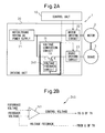
- Figure 2A is a block diagram showing the configuration of a motor driving apparatus according to a first embodiment of the present invention
- Figure 2B is a diagram schematically showing a voltage feedback circuit shown in Figure 2A.
- the motor driving apparatus 1 shown in Figure 2A is an apparatus for driving a motor 2 and for actuating a brake 3, and includes a control unit 10 and a driving unit 20.
- Control unit 10 supplies a speed command for motor 2 and a brake application command or brake release command for brake 3 to driving unit 20.
- Brake 3 is a power-off brake, and motor 2 can be braked by de-energizing the coil of brake 3.
- Driving unit 20 includes a motor/brake driving DC power supply 21 which is used both as a motor driving power supply and as a brake driving power supply, a motor driving circuit 22 which receives a speed command for motor 2 from control unit 10 and drives motor 2 at the commanded speed, a brake driving circuit 23 which receives a brake application command or brake release command for brake 3 from control unit 10 and applies or releases brake 3 in accordance with the received command, and a voltage conversion circuit 24 for maintaining the voltage applied to brake 3 at a constant level during the period that the brake is disengaged from motor 2 by energizing the coil of brake 3.
- a motor/brake driving DC power supply 21 which is used both as a motor driving power supply and as a brake driving power supply
- a motor driving circuit 22 which receives a speed command for motor 2 from control unit 10 and drives motor 2 at the commanded speed
- a brake driving circuit 23 which receives a brake application command or brake release command for brake 3 from control unit 10 and applies or releases brake 3 in accordance with the received command
- Motor/brake driving DC power supply 21 is a power supply that is fed from an external three-phase power supply and that produces a DC voltage by AC/DC conversion.
- Motor driving circuit 22 receives a speed command for motor 2 from control unit 10, performs DC/AC conversion, and drives motor 2 by PWM control in accordance with the speed command.
- Brake driving circuit 23 receives DC power from motor/brake driving DC power supply 21, and applies the DC voltage directly to the coil of brake 3 in accordance with a brake application command or brake release command for brake 3 received from control unit 10.
- voltage conversion circuit 24 comprises a power transistor TR and voltage feedback circuit 240.
- the input from motor/brake driving DC power supply 21 is received at the collector C of the power transistor TR, and voltage feedback circuit 240 controls the current flowing to the base B of the TR so that a constant voltage is output from the emitter E of the TR to brake driving circuit 23.
- the voltage applied to brake 3 is thus controlled at a constant level by voltage conversion circuit 24.
- voltage feedback circuit 240 whose general configuration is shown in Figure 2B, an internally generated reference voltage is compared with a feedback voltage which represents the voltage supplied to the brake driving circuit 23, and a control voltage for controlling the base current of the power transistor TR in voltage conversion circuit 24 is obtained at the output of a differential amplifier 241 as a result of the comparison between the two voltages; voltage feedback circuit 240 then supplies the control voltage to the base B of the power transistor TR, thereby controlling the voltage supplied to brake driving circuit 23 at a constant level.
- the motor driving apparatus 1 According to the motor driving apparatus 1 according to the first embodiment described above, if the output voltage of motor/brake driving DC power supply 21 fluctuates during the driving of motor 2, the voltage applied to brake 3 can be maintained constant by voltage conversion circuit 24 which controls the input voltage to brake driving circuit 23 at a constant level. Since the voltage applied to brake 3 can be varied by voltage conversion circuit 24 irrespective of the supply voltage specification of brake 3, it becomes possible to use the motor/brake driving DC power supply for driving the brake as well as for driving the motor.
- FIG. 3 is a flowchart showing the operation of the motor driving apparatus according to the first embodiment of the present invention shown in Figure 2.
- the horizontal axis represents the time t.
- control unit 10 supplies a motor energization enable ENBL signal to motor driving circuit 22.
- motor energization enable ENBL signal is input, motor 2 is immediately energized and, after a finite time delay from the input of the motor energization enable ENBL signal, a brake energization enable ENBL signal to brake driving circuit 23 is input from control unit 10 to brake driving circuit 23.
- brake energization enable ENBL signal is input, brake 3 is immediately energized and, after a predetermined period of time, the brake switches from the brake applied (clutched) condition to the brake released condition.
- the brake energization enable ENBL signal being supplied from control unit 10 to brake driving circuit 23 is set from ON to OFF and, after a predetermined period of time, the brake switches from the brake released condition to the brake applied (clutched) condition.
- the motor energization enable ENBL signal being supplied from control unit 10 to motor driving circuit 22 is set from ON to OFF which is input to motor driving circuit 22.
- the reason for introducing the finite time delay during which the motor energized state overlaps the brake de-energized state is that, in the case of a robot arm, for example, if the energization of the motor is started or stopped at the same time that the brake is de-energized, the robot arm may fall of its own weight. For a load that will not fall of its own weight, there is no need introduce such a finite time delay.
- FIG 4 is a block diagram showing the configuration of a motor driving apparatus according to a second embodiment of the present invention.
- Motor driving apparatus 4 shown in Figure 4 is substantially the same as the motor driving apparatus 1 shown in Figure 2A, except that a voltage conversion circuit 44 is different and that a control signal is supplied from control unit 30 to voltage conversion circuit 44. That is, control unit 30, driving unit 40, motor/brake driving DC power supply 41, motor driving circuit 42, and brake driving circuit 43 shown in Figure 4 are substantially the same as control unit 10, driving unit 20, motor/brake driving DC power supply 21, motor driving circuit 22, and brake driving circuit 23, respectively, shown in Figure 2.
- Voltage conversion circuit 44 shown in Figure 4 is configured to control the input voltage to brake driving circuit 43 so that, when driving motor 2, a sufficiently high voltage is output in order to reduce the time required to release brake 3 but, after a predetermined period of time has elapsed from the start of the driving of motor 2, the voltage is held at a reduced level in order to minimize the deterioration of the coil of brake 3.
- FIG. 5 is a flowchart showing the operation of the motor driving apparatus according to the second embodiment of the present invention shown in Figure 4.
- the horizontal axis represents the time t.
- control unit 30 supplies a motor energization enable ENBL signal to motor driving circuit 42.
- motor energization enable ENBL signal is input, motor 2 is immediately energized, and after a finite time delay from the input of the motor energization enable ENBL signal, a brake energization enable ENBL signal to brake driving circuit 43 is input from control unit 30 to brake driving circuit 43.
- brake energization enable ENBL signal is input, brake 3 is immediately energized and, after a predetermined period of time, the brake switches from the brake applied (clutched) condition to the brake released condition.
- the brake energization enable ENBL signal being supplied from control unit 30 to brake driving circuit 43 is set from ON to OFF and, after a predetermined period of time, the brake switches from the brake released condition to the brake applied (clutched) condition.
- the motor energization enable ENBL signal being supplied from control unit 30 to motor driving circuit 42 is set from ON to OFF which is input to motor driving circuit 42.
- an output voltage control signal is input from control unit 30 to voltage conversion circuit 44 and held in that state for a predetermined period.
- Voltage conversion circuit 44 supplies a voltage to brake driving circuit 43 only during the period that the brake energization enable ENBL signal is being input.
- Voltage conversion circuit 44 performs control so that a higher voltage is supplied to brake driving circuit 43 for a predetermined.period after the output voltage control signal is input to voltage conversion circuit 44 than when the output voltage control signal is not input.
- voltage conversion circuit 44 performs control so that a lower voltage is supplied to brake driving circuit 43 than when the output voltage control signal is being input.
- Figures 6A and 6B are block diagrams showing the configuration of a motor driving apparatus according to a third embodiment of the present invention, and Figure 6B is a diagram schematically showing a voltage feedback circuit shown in Figure 2A.
- Motor driving apparatus 6 shown in Figures 6A and 6B is substantially the same as the motor driving apparatus 1 shown in Figure 2A, except that a voltage conversion circuit 64 is different and that an output voltage control signal is supplied from a control unit 50 to voltage conversion circuit 64 in the motor driving apparatus 6.
- control unit 50, driving unit 60, motor/brake driving DC power supply 61, motor driving circuit 62, and brake driving circuit 63 shown in Figure 6 are substantially the same as control unit 10, driving unit 20, motor/brake driving DC power supply 21, motor driving circuit 22, and brake driving circuit 23, respectively, shown in Figure 2A.
- Voltage conversion circuit 64 shown in Figure 6A is configured to control the input voltage to brake driving circuit 63 so that, when driving motor 2, a sufficiently high voltage is output in order to reduce the time required to release brake 3 but, after a predetermined time has elapsed from the start of the driving of motor 2, the voltage is held at a reduced level in order to minimize the deterioration of the coil of brake 3.
- voltage conversion circuit 64 comprises an IGBT and a voltage feedback circuit 640.
- the input from motor/brake driving DC power supply 61 is received at the collector C of the IGBT, and a pulse voltage proportional to the pulse signal applied to the gate G of the IGBT is output from the emitter E of the IGBT to brake driving circuit 63.
- the pulse signal applied to the gate G of the IGBT is controlled by voltage feedback circuit 640.
- an internally generated reference voltage is compared with a feedback voltage, i.e., an output voltage from a CR circuit 642 which receives the voltage supplied to brake driving circuit 63 (the voltage output from the emitter E of the IGBT) and which outputs a voltage proportional to the duty cycle of the pulse, a control voltage output from a differential amplifier 641 as a result of the comparison between the two voltages is compared in a comparator 643 with an internally generated PWM control triangular wave, and the result of the comparison, output as a pulse width voltage command, is applied to the gate G of the IGBT, thereby controlling the voltage supplied to brake driving circuit 63.
- a feedback voltage i.e., an output voltage from a CR circuit 642 which receives the voltage supplied to brake driving circuit 63 (the voltage output from the emitter E of the IGBT) and which outputs a voltage proportional to the duty cycle of the pulse
- a control voltage output from a differential amplifier 641 as a result of the comparison between the two voltages
- CR circuit 642 is a circuit that charges with the time constant C1R1 of a resistor R2 and capacitor C1 and discharges electrical energy stored on the capacitor C1 through a resistor R2; a high-frequency pulse is input to this circuit, and a voltage proportion to the duty cycle of the pulse is output.
- FIG. 7 is a flowchart showing the operation of the motor driving apparatus according to the third embodiment of the present invention shown in Figures 6A and 6B.
- the horizontal axis represents the time t.
- control unit 50 supplies a motor energization enable ENBL signal to motor driving circuit 62.
- motor energization enable ENBL signal is input, motor 2 is immediately energized, and after a finite time delay from the input of the motor energization enable ENBL signal, a brake energization enable ENBL signal to brake driving circuit 63 is input from control unit 50 to brake driving circuit 63.
- brake energization enable ENBL signal is input, brake 3 is immediately energized, and after a predetermined period of time, the brake switches from the brake applied (clutched) condition to the brake released condition.
- the brake energization enable ENBL signal being supplied from control unit 50 to brake driving circuit 63 is set from ON to OFF, and after a predetermined period of time, the brake switches from the brake released condition to the brake applied (clutched) condition.
- the motor energization enable ENBL signal being supplied from control unit 50 to motor driving circuit 62 is set from ON to OFF which is input to motor driving circuit 62.
- an output voltage control signal is input from control unit 50 to voltage conversion circuit 64 and held in that state for a predetermined period.
- Voltage conversion circuit 64 supplies a voltage to brake driving circuit 63 only during the period that the brake energization enable ENBL signal is being input.
- Voltage conversion circuit 64 performs control so that a pulse voltage with a higher duty cycle is supplied to brake driving circuit 63 for a predetermined period after the output voltage control signal is input to voltage conversion circuit 64 than when the output voltage control signal is not input.
- voltage conversion circuit 64 When the output voltage control signal ceases to be input, voltage conversion circuit 64 performs control so that a pulse voltage with a lower duty cycle is supplied to brake driving circuit 63 than when the output voltage control signal is being input. By thus controlling the duty cycle of the pulse voltage supplied from voltage conversion circuit 64 to brake driving circuit 63, the operating time of brake 3 can be reduced.
- the voltage conversion circuit which controls the brake driving voltage by means of feedback, if motor driving power fluctuates, stable brake driving power can be supplied to the brake, stabilizing the voltage applied to the brake coil and thus serving to suppress loss in the brake coil. Furthermore, with the provision of the voltage conversion circuit, a single power supply can be used both as the motor driving power supply and as the brake driving power supply.
- the time required to release the brake can be reduced, and by reducing the applied voltage when holding the brake in the released condition, the time required to effect the braking (to hold the brake in a clutched condition) can be reduced. Furthermore, by reducing the voltage when holding the brake, the loss in the brake coil can be reduced, which serves to reduce the size of the brake.
Landscapes
- Engineering & Computer Science (AREA)
- Power Engineering (AREA)
- Stopping Of Electric Motors (AREA)
- Connection Of Motors, Electrical Generators, Mechanical Devices, And The Like (AREA)
Abstract
Description
- The present invention relates to a motor driving apparatus for driving and braking a brake-equipped motor used in a machine tool, an industrial machine, a robot, or the like.
- Motor driving apparatus for driving and braking a brake-equipped motor used in a machine tool, an industrial machine, a robot, or the like include the type that has a DC power supply which is used both as a motor driving power supply and as a brake driving power supply.
-
Patent Document 1 discloses a brake control method for a robot in which, to prevent, for example, a robot arm from falling in the event of an emergency stop or power interruption, a brake is provided within a motor or on a rotating shaft that moves the robot arm, with provisions made to actuate the brake by de-energizing the brake coil upon occurrence of an emergency stop or power interruption. - Figure 1 is a block diagram showing the configuration of a motor driving apparatus according to the prior art.
Motor driving apparatus 101 is an apparatus for driving amotor 102 and for actuating abrake 103, and includes acontrol unit 110 and adriving unit 120.Control unit 110 supplies a speed command formotor 102 and a brake application command or brake release command forbrake 103 to drivingunit 120. Brake 103 is a power-off brake, andmotor 102 can be braked by de-energizing the coil ofbrake 103.Driving unit 120 includes a motor/brake drivingDC power supply 121 which is used both as a motor driving power supply and as a brake driving power supply, amotor driving circuit 122 which receives a speed command formotor 102 fromcontrol unit 110 and drivesmotor 102 at the commanded speed, and abrake driving circuit 123 which receives a brake application command or brake release command forbrake 103 fromcontrol unit 110 and applies or releasesbrake 103 in accordance with the received command. -
Patent Document 2 discloses an electromagnetic brake control apparatus which, when drawing a moving plate in an electromagnetic braking device by attraction (forceful energization state), performs control so that a large current is flown only during the drawing stroke that lasts briefly, and thereafter, the current flowing to the electromagnet of the electromagnetic brake is held at a relatively small level just sufficient to hold the moving plate in the attracted position (sustained energization state) by accurately controlling the energization current to the electromagnet at all times independently of the operating condition of the electromagnetic brake, that is, by properly controlling the energization current to the electromagnet of the electromagnetic brake so as to ensure high reliability and stable braking action while achieving sufficient energy saving. This electromagnetic brake control apparatus employs a method that controls the energization current to the electromagnetic brake actuating electromagnet through phase control by a thyristor from a commercial AC power supply, and detects the energization current supplied to the electromagnet of the electromagnetic brake and controls the firing angle of the thyristor in accordance with the deviation of the detected value from a reference value. -
- [Patent Document 1]
Japanese Unexamined Patent Publication No. H07-328966 - [Patent Document 2]
Japanese Unexamined Patent Publication No. H06-200963 - In the brake control method for a robot disclosed in
Patent Document 1, the motor/brake driving DC power supply is used for driving the brake as well as for driving the motor, but in this case, because of the fluctuation in supply voltage during the driving of the motor, in particular, the fluctuation in supply voltage associated with the acceleration and deceleration of the motor, the voltage applied to the brake coil as the brake driving power becomes unstable, and in the worst case, the brake coil may be damaged. - In the electromagnetic brake control apparatus disclosed in
Patent Document 2, while improvements can be achieved in terms of the stability of braking action and the reduction of energy consumption, reducing the time required to release the brake or effect the braking is not considered. - The present invention has been devised to solve the above problems, and an object of the invention is to provide a motor driving apparatus wherein provisions are made to suppress the fluctuation in supply voltage that occurs during the driving of the motor due to the use of the motor/brake driving DC power supply for driving the brake as well as for driving the motor, to stabilize the braking action, to prevent the deterioration of the brake coil, and to reduce the time required to release the brake as well as the time required to effect the braking.
- A motor driving apparatus according to
claim 1, which accomplishes the above object, is a motor driving apparatus for driving and braking a motor equipped with a brake, comprising a motor/brake driving DC power supply which is used both as a motor driving power supply and as a brake driving power supply, wherein when the motor/brake driving DC power supply is being used as the motor driving power supply, a voltage conversion circuit via which a voltage supplied from the motor/brake driving DC power supply is applied to the brake feedback-controls the voltage applied to the brake. - In the above motor driving apparatus, when the motor/brake driving DC power supply is being used as the motor driving power supply, the voltage conversion circuit increases the voltage applied to the brake for a predetermined period immediately after the brake is released, and reduces the applied voltage when holding the brake in a released condition after the predetermined period has elapsed.
- In the above motor driving apparatus, the voltage conversion circuit performs voltage control by pulse width modulation PWM.
-
- Figure 1 is a block diagram showing the configuration of a motor driving apparatus according to the prior art,
- Figure 2A is a block diagram showing the configuration of a motor driving apparatus according to a first embodiment of the present invention,
- Figure 2B is a diagram schematically showing a voltage feedback circuit shown in Figure 2A.
- Figure 3 is a flowchart showing the operation of the motor driving apparatus according to the first embodiment of the present invention shown in Figures 2A and 2B,
- Figure 4 is a block diagram showing the configuration of a motor driving apparatus according to a second embodiment of the present invention,
- Figure 5 is a flowchart showing the operation of the motor driving apparatus according to the second embodiment of the present invention shown in Figure 4,
- Figure 6A is a block diagram showing the configuration of a motor driving apparatus according to a third embodiment of the present invention,
- Figure 6B is a diagram schematically showing a voltage feedback circuit shown in Figure 6A, and
- Figure 7 is a flowchart showing the operation of the motor driving apparatus according to the third embodiment of the present invention shown in Figures 6A and 6B.
- The embodiments of the present invention will be described in detail below with reference to the accompanying drawings.
Figure 2A is a block diagram showing the configuration of a motor driving apparatus according to a first embodiment of the present invention, and Figure 2B is a diagram schematically showing a voltage feedback circuit shown in Figure 2A. - The
motor driving apparatus 1 shown in Figure 2A is an apparatus for driving amotor 2 and for actuating abrake 3, and includes acontrol unit 10 and adriving unit 20.Control unit 10 supplies a speed command formotor 2 and a brake application command or brake release command forbrake 3 to drivingunit 20. Brake 3 is a power-off brake, andmotor 2 can be braked by de-energizing the coil ofbrake 3.Driving unit 20 includes a motor/brake drivingDC power supply 21 which is used both as a motor driving power supply and as a brake driving power supply, amotor driving circuit 22 which receives a speed command formotor 2 fromcontrol unit 10 and drivesmotor 2 at the commanded speed, abrake driving circuit 23 which receives a brake application command or brake release command forbrake 3 fromcontrol unit 10 and applies or releasesbrake 3 in accordance with the received command, and avoltage conversion circuit 24 for maintaining the voltage applied tobrake 3 at a constant level during the period that the brake is disengaged frommotor 2 by energizing the coil ofbrake 3. - Motor/brake driving
DC power supply 21 is a power supply that is fed from an external three-phase power supply and that produces a DC voltage by AC/DC conversion.Motor driving circuit 22 receives a speed command formotor 2 fromcontrol unit 10, performs DC/AC conversion, and drivesmotor 2 by PWM control in accordance with the speed command. Brakedriving circuit 23 receives DC power from motor/brake drivingDC power supply 21, and applies the DC voltage directly to the coil ofbrake 3 in accordance with a brake application command or brake release command forbrake 3 received fromcontrol unit 10. - As shown in Figure 2A,
voltage conversion circuit 24 comprises a power transistor TR andvoltage feedback circuit 240. In thevoltage conversion circuit 24, the input from motor/brake drivingDC power supply 21 is received at the collector C of the power transistor TR, andvoltage feedback circuit 240 controls the current flowing to the base B of the TR so that a constant voltage is output from the emitter E of the TR tobrake driving circuit 23. The voltage applied tobrake 3 is thus controlled at a constant level byvoltage conversion circuit 24. - In
voltage feedback circuit 240 whose general configuration is shown in Figure 2B, an internally generated reference voltage is compared with a feedback voltage which represents the voltage supplied to thebrake driving circuit 23, and a control voltage for controlling the base current of the power transistor TR involtage conversion circuit 24 is obtained at the output of adifferential amplifier 241 as a result of the comparison between the two voltages;voltage feedback circuit 240 then supplies the control voltage to the base B of the power transistor TR, thereby controlling the voltage supplied tobrake driving circuit 23 at a constant level. - According to the
motor driving apparatus 1 according to the first embodiment described above, if the output voltage of motor/brake drivingDC power supply 21 fluctuates during the driving ofmotor 2, the voltage applied tobrake 3 can be maintained constant byvoltage conversion circuit 24 which controls the input voltage to brakedriving circuit 23 at a constant level. Since the voltage applied tobrake 3 can be varied byvoltage conversion circuit 24 irrespective of the supply voltage specification ofbrake 3, it becomes possible to use the motor/brake driving DC power supply for driving the brake as well as for driving the motor. - Figure 3 is a flowchart showing the operation of the motor driving apparatus according to the first embodiment of the present invention shown in Figure 2. The horizontal axis represents the time t. When driving
motor 2,control unit 10 supplies a motor energization enable ENBL signal to motordriving circuit 22. When the motor energization enable ENBL signal is input,motor 2 is immediately energized and, after a finite time delay from the input of the motor energization enable ENBL signal, a brake energization enable ENBL signal to brakedriving circuit 23 is input fromcontrol unit 10 tobrake driving circuit 23. When the brake energization enable ENBL signal is input,brake 3 is immediately energized and, after a predetermined period of time, the brake switches from the brake applied (clutched) condition to the brake released condition. - When stopping
motor 2, the brake energization enable ENBL signal being supplied fromcontrol unit 10 tobrake driving circuit 23 is set from ON to OFF and, after a predetermined period of time, the brake switches from the brake released condition to the brake applied (clutched) condition. After a finite time delay from the ON-to-OFF switching of the brake energization enable ENBL signal, the motor energization enable ENBL signal being supplied fromcontrol unit 10 tomotor driving circuit 22 is set from ON to OFF which is input tomotor driving circuit 22. When the motor energization enable ENBL signal becomes OFF,motor 2 is immediately de-energized and thus stops. - The reason for introducing the finite time delay during which the motor energized state overlaps the brake de-energized state is that, in the case of a robot arm, for example, if the energization of the motor is started or stopped at the same time that the brake is de-energized, the robot arm may fall of its own weight. For a load that will not fall of its own weight, there is no need introduce such a finite time delay.
- Figure 4 is a block diagram showing the configuration of a motor driving apparatus according to a second embodiment of the present invention.
Motor driving apparatus 4 shown in Figure 4 is substantially the same as themotor driving apparatus 1 shown in Figure 2A, except that avoltage conversion circuit 44 is different and that a control signal is supplied fromcontrol unit 30 tovoltage conversion circuit 44. That is,control unit 30,driving unit 40, motor/brake drivingDC power supply 41,motor driving circuit 42, andbrake driving circuit 43 shown in Figure 4 are substantially the same ascontrol unit 10,driving unit 20, motor/brake drivingDC power supply 21,motor driving circuit 22, andbrake driving circuit 23, respectively, shown in Figure 2. -
Voltage conversion circuit 44 shown in Figure 4 is configured to control the input voltage to brakedriving circuit 43 so that, when drivingmotor 2, a sufficiently high voltage is output in order to reduce the time required to releasebrake 3 but, after a predetermined period of time has elapsed from the start of the driving ofmotor 2, the voltage is held at a reduced level in order to minimize the deterioration of the coil ofbrake 3. - Figure 5 is a flowchart showing the operation of the motor driving apparatus according to the second embodiment of the present invention shown in Figure 4. The horizontal axis represents the time t. When driving
motor 2,control unit 30 supplies a motor energization enable ENBL signal tomotor driving circuit 42. When the motor energization enable ENBL signal is input,motor 2 is immediately energized, and after a finite time delay from the input of the motor energization enable ENBL signal, a brake energization enable ENBL signal to brake drivingcircuit 43 is input fromcontrol unit 30 to brake drivingcircuit 43. When the brake energization enable ENBL signal is input,brake 3 is immediately energized and, after a predetermined period of time, the brake switches from the brake applied (clutched) condition to the brake released condition. - When stopping
motor 2, the brake energization enable ENBL signal being supplied fromcontrol unit 30 to brake drivingcircuit 43 is set from ON to OFF and, after a predetermined period of time, the brake switches from the brake released condition to the brake applied (clutched) condition. After a finite time delay from the ON-to-OFF switching of the brake energization enable ENBL signal, the motor energization enable ENBL signal being supplied fromcontrol unit 30 tomotor driving circuit 42 is set from ON to OFF which is input tomotor driving circuit 42. When the motor energization enable ENBL signal becomes OFF,motor 2 is immediately de-energized and thus stops. - At the same time that the brake energization enable ENBL signal is input from
control unit 30 to brake drivingcircuit 43, an output voltage control signal is input fromcontrol unit 30 tovoltage conversion circuit 44 and held in that state for a predetermined period.Voltage conversion circuit 44 supplies a voltage to brake drivingcircuit 43 only during the period that the brake energization enable ENBL signal is being input.Voltage conversion circuit 44 performs control so that a higher voltage is supplied to brake drivingcircuit 43 for a predetermined.period after the output voltage control signal is input tovoltage conversion circuit 44 than when the output voltage control signal is not input.
When the output voltage control signal ceases to be input,voltage conversion circuit 44 performs control so that a lower voltage is supplied to brake drivingcircuit 43 than when the output voltage control signal is being input. By thus controlling the voltage supplied fromvoltage conversion circuit 44 to brake drivingcircuit 43, the operating time ofbrake 3 can be reduced. - Figures 6A and 6B are block diagrams showing the configuration of a motor driving apparatus according to a third embodiment of the present invention, and Figure 6B is a diagram schematically showing a voltage feedback circuit shown in Figure 2A.
Motor driving apparatus 6 shown in Figures 6A and 6B is substantially the same as themotor driving apparatus 1 shown in Figure 2A, except that avoltage conversion circuit 64 is different and that an output voltage control signal is supplied from acontrol unit 50 tovoltage conversion circuit 64 in themotor driving apparatus 6. That is,control unit 50, drivingunit 60, motor/brake drivingDC power supply 61,motor driving circuit 62, and brake drivingcircuit 63 shown in Figure 6 are substantially the same ascontrol unit 10, drivingunit 20, motor/brake drivingDC power supply 21,motor driving circuit 22, and brake drivingcircuit 23, respectively, shown in Figure 2A. -
Voltage conversion circuit 64 shown in Figure 6A is configured to control the input voltage to brake drivingcircuit 63 so that, when drivingmotor 2, a sufficiently high voltage is output in order to reduce the time required to releasebrake 3 but, after a predetermined time has elapsed from the start of the driving ofmotor 2, the voltage is held at a reduced level in order to minimize the deterioration of the coil ofbrake 3. - As shown in Figure 6A,
voltage conversion circuit 64 comprises an IGBT and avoltage feedback circuit 640. Involtage conversion circuit 64, the input from motor/brake drivingDC power supply 61 is received at the collector C of the IGBT, and a pulse voltage proportional to the pulse signal applied to the gate G of the IGBT is output from the emitter E of the IGBT to brake drivingcircuit 63. The pulse signal applied to the gate G of the IGBT is controlled byvoltage feedback circuit 640. - In
voltage feedback circuit 640 whose general configuration is shown in Figure 6B, an internally generated reference voltage is compared with a feedback voltage, i.e., an output voltage from aCR circuit 642 which receives the voltage supplied to brake driving circuit 63 (the voltage output from the emitter E of the IGBT) and which outputs a voltage proportional to the duty cycle of the pulse, a control voltage output from adifferential amplifier 641 as a result of the comparison between the two voltages is compared in acomparator 643 with an internally generated PWM control triangular wave, and the result of the comparison, output as a pulse width voltage command, is applied to the gate G of the IGBT, thereby controlling the voltage supplied to brake drivingcircuit 63.CR circuit 642 is a circuit that charges with the time constant C1R1 of a resistor R2 and capacitor C1 and discharges electrical energy stored on the capacitor C1 through a resistor R2; a high-frequency pulse is input to this circuit, and a voltage proportion to the duty cycle of the pulse is output. - Figure 7 is a flowchart showing the operation of the motor driving apparatus according to the third embodiment of the present invention shown in Figures 6A and 6B. The horizontal axis represents the time t. When driving
motor 2,control unit 50 supplies a motor energization enable ENBL signal tomotor driving circuit 62. When the motor energization enable ENBL signal is input,motor 2 is immediately energized, and after a finite time delay from the input of the motor energization enable ENBL signal, a brake energization enable ENBL signal to brake drivingcircuit 63 is input fromcontrol unit 50 to brake drivingcircuit 63. When the brake energization enable ENBL signal is input,brake 3 is immediately energized, and after a predetermined period of time, the brake switches from the brake applied (clutched) condition to the brake released condition. - When stopping
motor 2, the brake energization enable ENBL signal being supplied fromcontrol unit 50 to brake drivingcircuit 63 is set from ON to OFF, and after a predetermined period of time, the brake switches from the brake released condition to the brake applied (clutched) condition. After a finite time delay from the ON-to-OFF switching of the brake energization enable ENBL signal, the motor energization enable ENBL signal being supplied fromcontrol unit 50 tomotor driving circuit 62 is set from ON to OFF which is input tomotor driving circuit 62. When the motor energization enable ENBL signal becomes OFF,motor 2 is immediately de-energized and thus stops. - At the same time that the brake energization enable ENBL signal is input from
control unit 50 to brake drivingcircuit 63, an output voltage control signal is input fromcontrol unit 50 tovoltage conversion circuit 64 and held in that state for a predetermined period.Voltage conversion circuit 64 supplies a voltage to brake drivingcircuit 63 only during the period that the brake energization enable ENBL signal is being input.Voltage conversion circuit 64 performs control so that a pulse voltage with a higher duty cycle is supplied to brake drivingcircuit 63 for a predetermined period after the output voltage control signal is input tovoltage conversion circuit 64 than when the output voltage control signal is not input. When the output voltage control signal ceases to be input,voltage conversion circuit 64 performs control so that a pulse voltage with a lower duty cycle is supplied to brake drivingcircuit 63 than when the output voltage control signal is being input. By thus controlling the duty cycle of the pulse voltage supplied fromvoltage conversion circuit 64 to brake drivingcircuit 63, the operating time ofbrake 3 can be reduced. - According to the invention described in
claim 1, because of the provision of the voltage conversion circuit which controls the brake driving voltage by means of feedback, if motor driving power fluctuates, stable brake driving power can be supplied to the brake, stabilizing the voltage applied to the brake coil and thus serving to suppress loss in the brake coil.
Furthermore, with the provision of the voltage conversion circuit, a single power supply can be used both as the motor driving power supply and as the brake driving power supply. - According to the invention described in
claim 2, by increasing the applied voltage when releasing the brake from the actuated condition, the time required to release the brake can be reduced, and by reducing the applied voltage when holding the brake in the released condition, the time required to effect the braking (to hold the brake in a clutched condition) can be reduced.
Furthermore, by reducing the voltage when holding the brake, the loss in the brake coil can be reduced, which serves to reduce the size of the brake. - According to the invention described in
claim 3, since the output voltage of the voltage conversion circuit can be precisely adjusted, the loss in the brake coil can be further reduced.
Claims (3)
- A motor driving apparatus for driving and braking a motor equipped with a brake, comprising a motor/brake driving DC power supply which is used both as a motor driving power supply and as a brake driving power supply, wherein
when said motor/brake driving DC power supply is being used as said motor driving power supply, a voltage conversion circuit via which a voltage supplied from said motor/brake driving DC power supply is applied to said brake feedback-controls the voltage applied to said brake. - A motor driving apparatus as claimed in claim 1, wherein when said motor/brake driving DC power supply is being used as said motor driving power supply, said voltage conversion circuit increases the voltage applied to said brake for a predetermined period immediately after said brake is released, and reduces said applied voltage when holding said brake in a released condition after said predetermined period has elapsed.
- A motor driving apparatus as claimed in claim 1 or 2, wherein said voltage conversion circuit performs said voltage control by pulse width modulation PWM.
Applications Claiming Priority (1)
| Application Number | Priority Date | Filing Date | Title |
|---|---|---|---|
| JP2006314703A JP4202384B2 (en) | 2006-11-21 | 2006-11-21 | Motor drive device for driving and braking a motor with a brake |
Publications (2)
| Publication Number | Publication Date |
|---|---|
| EP1926203A2 true EP1926203A2 (en) | 2008-05-28 |
| EP1926203A3 EP1926203A3 (en) | 2012-09-12 |
Family
ID=39203339
Family Applications (1)
| Application Number | Title | Priority Date | Filing Date |
|---|---|---|---|
| EP07019917A Ceased EP1926203A3 (en) | 2006-11-21 | 2007-10-11 | Motor driving apparatus for driving and braking brake-equipped motor |
Country Status (4)
| Country | Link |
|---|---|
| US (1) | US7898196B2 (en) |
| EP (1) | EP1926203A3 (en) |
| JP (1) | JP4202384B2 (en) |
| CN (1) | CN101186037B (en) |
Cited By (1)
| Publication number | Priority date | Publication date | Assignee | Title |
|---|---|---|---|---|
| US11571808B2 (en) | 2019-10-28 | 2023-02-07 | Fanuc Corporation | Rotary axis module and robot |
Families Citing this family (15)
| Publication number | Priority date | Publication date | Assignee | Title |
|---|---|---|---|---|
| US8746812B2 (en) * | 2004-10-08 | 2014-06-10 | Marcia Albright | Brake control unit |
| JP2008307618A (en) * | 2007-06-12 | 2008-12-25 | Denso Wave Inc | Robot control device |
| CN102256755B (en) * | 2008-12-17 | 2014-09-17 | Abb研究有限公司 | Damage-preventing system for manipulator |
| JP5334785B2 (en) * | 2009-09-30 | 2013-11-06 | 三菱電機Fa産業機器株式会社 | Non-excitation actuated electromagnetic brake control device and method |
| DE102010040565A1 (en) * | 2010-09-10 | 2012-03-15 | Robert Bosch Gmbh | Method for adjusting the clamping force exerted by a parking brake |
| DE102012003479A1 (en) * | 2012-02-21 | 2013-08-22 | Kuka Roboter Gmbh | Method and device for carrying out a manipulator process |
| US9114536B2 (en) * | 2012-04-13 | 2015-08-25 | Rethink Robotics, Inc. | Electronic emergency-stop braking circuit for robotic arms |
| JP2013240195A (en) * | 2012-05-15 | 2013-11-28 | Mitsubishi Electric Corp | Acceleration deceleration controller |
| WO2014045728A1 (en) * | 2012-09-21 | 2014-03-27 | 富士電機株式会社 | Electromagnetic brake control device |
| EP2851909B1 (en) * | 2013-09-18 | 2017-08-02 | Siemens Aktiengesellschaft | Drive system with combined control of the brake and transducer |
| DE102013020697B4 (en) * | 2013-12-04 | 2023-07-06 | Kuka Roboter Gmbh | Method and control means for controlling a robot |
| DE102015216496A1 (en) * | 2015-08-28 | 2017-03-02 | Dr. Johannes Heidenhain Gmbh | circuitry |
| CN110023046B (en) * | 2017-02-22 | 2023-03-21 | Abb瑞士股份有限公司 | Industrial robot system with monitoring sensor |
| JP2019140350A (en) * | 2018-02-15 | 2019-08-22 | 日本電産株式会社 | Brake drive control circuit |
| CN109687770A (en) * | 2018-12-29 | 2019-04-26 | 上海辛格林纳新时达电机有限公司 | The band-type brake coil control circuit and system of servo-driver |
Citations (4)
| Publication number | Priority date | Publication date | Assignee | Title |
|---|---|---|---|---|
| US4509620A (en) | 1982-03-08 | 1985-04-09 | Dresser Industries, Inc. | Hoist or the like |
| US5049793A (en) * | 1986-04-10 | 1991-09-17 | Kabushiki Kaisha Yasakawa Denki Seisakusho | Method of controlling V/F inverter for machines having mechanical braking systems |
| JPH07328966A (en) * | 1994-06-07 | 1995-12-19 | Fanuc Ltd | Brake control system for robot |
| US5892341A (en) * | 1997-10-29 | 1999-04-06 | Rexnord Corporation | Quick set electric motor brake control |
Family Cites Families (18)
| Publication number | Priority date | Publication date | Assignee | Title |
|---|---|---|---|---|
| US4937509A (en) * | 1988-10-14 | 1990-06-26 | Acraloc Corporation | Electronic braking circuit for rotating AC electrical motors |
| JPH0768016B2 (en) * | 1988-12-23 | 1995-07-26 | 三菱電機株式会社 | AC elevator control device |
| US5090518A (en) * | 1990-05-31 | 1992-02-25 | General Motors Corporation | Brake control system |
| DE4220122A1 (en) * | 1992-06-16 | 1993-12-23 | Mannesmann Ag | Control circuit for DC-operated brakes of pole-changing three-phase motors |
| JPH06200963A (en) | 1993-01-07 | 1994-07-19 | Hitachi Ltd | Control device for electromagnetic brake |
| DE69836301T2 (en) * | 1997-07-29 | 2007-06-06 | Toyota Jidosha Kabushiki Kaisha, Toyota | Electrically operated brake system with an electric brake motor actuator for obtaining a relationship between engine power and braking torque |
| DE19740016C2 (en) * | 1997-09-11 | 2002-04-25 | Sew Eurodrive Gmbh & Co | Circuit arrangement and method for operating an excitation coil of an electromagnetically actuable, mechanical brake of an electric motor |
| US6291951B1 (en) * | 2000-03-21 | 2001-09-18 | Valiant Machine & Tool Inc. | Holding brake control circuit for servo-motor |
| JP2001278554A (en) | 2000-03-29 | 2001-10-10 | Mitsubishi Electric Corp | Elevator electromagnetic brake controller |
| JP2004122838A (en) * | 2002-08-07 | 2004-04-22 | Asmo Co Ltd | Electric parking brake system and method for controlling electric parking brake system |
| JP2004314195A (en) | 2003-04-11 | 2004-11-11 | Yaskawa Electric Corp | Industrial robot |
| JP2004320945A (en) * | 2003-04-18 | 2004-11-11 | Yaskawa Electric Corp | AC servo driver motor power line disconnection detection method |
| JP2005067409A (en) * | 2003-08-25 | 2005-03-17 | Asmo Co Ltd | Electric parking brake device and its control method |
| JP4418259B2 (en) * | 2004-02-27 | 2010-02-17 | 株式会社日立製作所 | Electric brake device |
| DE102004013033B3 (en) * | 2004-03-16 | 2005-07-14 | Sew-Eurodrive Gmbh & Co. Kg | Drive for industrial use has brake(s) and electric motor supplied with alternating current from end stage via supply lines; brake is supplied from brake controller connected via capacitor(s) to supply line(s) and is supplied from this |
| DE102005027502B4 (en) * | 2004-10-22 | 2009-07-09 | Sew-Eurodrive Gmbh & Co. Kg | Electromagnetically actuated brake, device for safe control of an electromagnetically actuated brake, electric motor and brake |
| JP2006219082A (en) * | 2005-02-14 | 2006-08-24 | Hitachi Ltd | Rotating electrical machine system for vehicles |
| JP2006304537A (en) | 2005-04-22 | 2006-11-02 | Yaskawa Electric Corp | Electromagnetic brake control device for motor |
-
2006
- 2006-11-21 JP JP2006314703A patent/JP4202384B2/en active Active
-
2007
- 2007-10-11 EP EP07019917A patent/EP1926203A3/en not_active Ceased
- 2007-10-14 US US11/872,019 patent/US7898196B2/en active Active
- 2007-11-20 CN CN2007101887775A patent/CN101186037B/en active Active
Patent Citations (5)
| Publication number | Priority date | Publication date | Assignee | Title |
|---|---|---|---|---|
| US4509620A (en) | 1982-03-08 | 1985-04-09 | Dresser Industries, Inc. | Hoist or the like |
| US5049793A (en) * | 1986-04-10 | 1991-09-17 | Kabushiki Kaisha Yasakawa Denki Seisakusho | Method of controlling V/F inverter for machines having mechanical braking systems |
| JPH07328966A (en) * | 1994-06-07 | 1995-12-19 | Fanuc Ltd | Brake control system for robot |
| US5892341A (en) * | 1997-10-29 | 1999-04-06 | Rexnord Corporation | Quick set electric motor brake control |
| US5892341B1 (en) * | 1997-10-29 | 2000-06-27 | Rexnord Corp | Quick set electric motor brake control |
Cited By (1)
| Publication number | Priority date | Publication date | Assignee | Title |
|---|---|---|---|---|
| US11571808B2 (en) | 2019-10-28 | 2023-02-07 | Fanuc Corporation | Rotary axis module and robot |
Also Published As
| Publication number | Publication date |
|---|---|
| CN101186037A (en) | 2008-05-28 |
| CN101186037B (en) | 2010-12-15 |
| US20080116828A1 (en) | 2008-05-22 |
| US7898196B2 (en) | 2011-03-01 |
| JP4202384B2 (en) | 2008-12-24 |
| JP2008131759A (en) | 2008-06-05 |
| EP1926203A3 (en) | 2012-09-12 |
Similar Documents
| Publication | Publication Date | Title |
|---|---|---|
| US7898196B2 (en) | Motor driving apparatus for driving and braking brake-equipped motor | |
| US5247140A (en) | Brake control system in elevator control apparatus | |
| JP2000116185A (en) | Improved method and device for electronically-braking dc motor | |
| JP4607631B2 (en) | Brake control device for elevator | |
| CN105060037B (en) | Brake control method and system | |
| JP2019221131A (en) | Short circuit brake of long stator linear motor | |
| JP4811952B2 (en) | Non-excitation electromagnetic brake | |
| US6311801B1 (en) | Brake control apparatus with auxiliary power source means | |
| CN107912052B (en) | Method for controlling a rotor blade adjustment device | |
| JP4403614B2 (en) | Elevator braking device | |
| WO2019159720A1 (en) | Brake drive control circuit | |
| CN110957943A (en) | Band-type brake control method of servo motor | |
| US4984126A (en) | Method and circuit for stopping the test run of a rotor being balanced | |
| EP0045484B1 (en) | An electric sewing machine driving apparatus | |
| JP4774282B2 (en) | Brake control device for elevator | |
| JPH0522968A (en) | Electromagnetic brake exciter | |
| JP2011200073A (en) | Motor drive | |
| JP3026877B2 (en) | Electromagnet control device | |
| JP5495550B2 (en) | Motor control method and power supply device | |
| JP2708654B2 (en) | Control device for hydraulic elevator | |
| JP5875494B2 (en) | Electromagnetic brake control device | |
| JPH08157014A (en) | Emergently stopping method of elevating body and device thereof | |
| JPH0615899U (en) | Drive control device for solenoid valve used in press machine | |
| JPH11347874A (en) | Stop control device for machine tool | |
| KR20190089932A (en) | Robot control device and robot equipped with this control device |
Legal Events
| Date | Code | Title | Description |
|---|---|---|---|
| PUAI | Public reference made under article 153(3) epc to a published international application that has entered the european phase |
Free format text: ORIGINAL CODE: 0009012 |
|
| AK | Designated contracting states |
Kind code of ref document: A2 Designated state(s): AT BE BG CH CY CZ DE DK EE ES FI FR GB GR HU IE IS IT LI LT LU LV MC MT NL PL PT RO SE SI SK TR |
|
| AX | Request for extension of the european patent |
Extension state: AL BA HR MK RS |
|
| RAP1 | Party data changed (applicant data changed or rights of an application transferred) |
Owner name: FANUC CORPORATION |
|
| TPAC | Observations filed by third parties |
Free format text: ORIGINAL CODE: EPIDOSNTIPA |
|
| TPAC | Observations filed by third parties |
Free format text: ORIGINAL CODE: EPIDOSNTIPA |
|
| PUAL | Search report despatched |
Free format text: ORIGINAL CODE: 0009013 |
|
| AK | Designated contracting states |
Kind code of ref document: A3 Designated state(s): AT BE BG CH CY CZ DE DK EE ES FI FR GB GR HU IE IS IT LI LT LU LV MC MT NL PL PT RO SE SI SK TR |
|
| AX | Request for extension of the european patent |
Extension state: AL BA HR MK RS |
|
| RIC1 | Information provided on ipc code assigned before grant |
Ipc: H02P 3/16 20060101ALI20120803BHEP Ipc: H02P 29/04 20060101ALI20120803BHEP Ipc: H02P 3/26 20060101ALI20120803BHEP Ipc: H02P 3/04 20060101AFI20120803BHEP Ipc: H02P 15/00 20060101ALI20120803BHEP |
|
| 17P | Request for examination filed |
Effective date: 20130215 |
|
| AKX | Designation fees paid |
Designated state(s): DE |
|
| 17Q | First examination report despatched |
Effective date: 20130606 |
|
| STAA | Information on the status of an ep patent application or granted ep patent |
Free format text: STATUS: THE APPLICATION HAS BEEN REFUSED |
|
| 18R | Application refused |
Effective date: 20170926 |