EP1926100A1 - Spindle motor and disk player - Google Patents
Spindle motor and disk player Download PDFInfo
- Publication number
- EP1926100A1 EP1926100A1 EP07254345A EP07254345A EP1926100A1 EP 1926100 A1 EP1926100 A1 EP 1926100A1 EP 07254345 A EP07254345 A EP 07254345A EP 07254345 A EP07254345 A EP 07254345A EP 1926100 A1 EP1926100 A1 EP 1926100A1
- Authority
- EP
- European Patent Office
- Prior art keywords
- section
- rotor
- cartridge
- disk
- eject
- Prior art date
- Legal status (The legal status is an assumption and is not a legal conclusion. Google has not performed a legal analysis and makes no representation as to the accuracy of the status listed.)
- Granted
Links
Images











Classifications
-
- G—PHYSICS
- G11—INFORMATION STORAGE
- G11B—INFORMATION STORAGE BASED ON RELATIVE MOVEMENT BETWEEN RECORD CARRIER AND TRANSDUCER
- G11B19/00—Driving, starting, stopping record carriers not specifically of filamentary or web form, or of supports therefor; Control thereof; Control of operating function ; Driving both disc and head
- G11B19/20—Driving; Starting; Stopping; Control thereof
- G11B19/2009—Turntables, hubs and motors for disk drives; Mounting of motors in the drive
-
- H—ELECTRICITY
- H02—GENERATION; CONVERSION OR DISTRIBUTION OF ELECTRIC POWER
- H02K—DYNAMO-ELECTRIC MACHINES
- H02K1/00—Details of the magnetic circuit
- H02K1/06—Details of the magnetic circuit characterised by the shape, form or construction
- H02K1/22—Rotating parts of the magnetic circuit
- H02K1/27—Rotor cores with permanent magnets
- H02K1/2786—Outer rotors
- H02K1/2787—Outer rotors the magnetisation axis of the magnets being perpendicular to the rotor axis
- H02K1/2789—Outer rotors the magnetisation axis of the magnets being perpendicular to the rotor axis the rotor consisting of two or more circumferentially positioned magnets
- H02K1/2791—Surface mounted magnets; Inset magnets
Definitions
- the present invention relates to a spindle motor comprising a rotor, and a player including the spindle motor.
- a spindle motor 301 is attached to be erected on the upper surface side of a chassis 303 by a screw 304 or the like by placing a stator substrate 302 serving as a motor support plate on the upper surface of the chassis 303.
- the disk cartridge eject mechanism 107 including the eject lever 104, the eject spring 105, and the damper spring 106 is arranged in a space formed by the front surface of the disk cartridge 1 housed in the cartridge holder 101, the upper surface of the chassis 102, and the lower surface of the cartridge holder 101, i.e., a so-called dead space.
Landscapes
- Engineering & Computer Science (AREA)
- Power Engineering (AREA)
- Feeding And Guiding Record Carriers (AREA)
- Rotational Drive Of Disk (AREA)
- Holding Or Fastening Of Disk On Rotational Shaft (AREA)
- Connection Of Motors, Electrical Generators, Mechanical Devices, And The Like (AREA)
- Permanent Magnet Type Synchronous Machine (AREA)
Abstract
Description
- The present invention relates to a spindle motor comprising a rotor, and a player including the spindle motor.
- As shown in
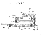
Figs. 34 and35 , in a player for a disk and the like, aspindle motor 301 is attached to be erected on the upper surface side of achassis 303 by ascrew 304 or the like by placing astator substrate 302 serving as a motor support plate on the upper surface of thechassis 303. Thespindle motor 301 includes atubular bearing section 305 provided in thestator substrate 302, abearing 306 attached to the inner periphery of thebearing section 305, awiring board 307 attached on thestator substrate 302, an iron-core coil 308 attached to the outer periphery of thetubular bearing section 305, a rotatingshaft 309 attached to thebearing 306, and arotor assembly 310 attached to the tip of the rotatingshaft 309. - The
rotor assembly 310 includes arotor 311 made of metal and a disk table 312 of synthetic resin outsert-molded in therotor 311. Arotor magnet 313 forming a pair with the iron-core coil 308 is attached to the inner peripheral surface of therotor 311. Achucking magnet 314 that magnetically chucks a hub of a disk-like recording medium is attached to the upper surface of the disk table 312. A centeringspring 315 is arranged at the outer periphery of themagnet 314. - As shown in
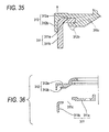
Fig. 36 in which therotor 311 and the disk table 312 are separated, therotor 311 has a substantially circulartop surface section 311 a and atubular skirt section 311b. The disk table 312 is outsert-molded with thetubular skirt section 311b arranged at apredetermined space 311 c from the outer periphery of thetop surface section 311a. On the other hand, the disk table 312 includes a tablemain body section 312a located on the outer surface side of therotor 311 and a rotor-inner-surfacesuperimposing section 312b that is located on the inner surface side of therotor 311 and integrally combine the tablemain body section 312a with therotor 311. When the disk table 312 is resin-molded, the rotor-inner-surfacesuperimposing section 312b is formed by extending a part of the resin to the inner surface side of therotor 311 through thespace 311c between thetop surface section 311 a and thetubular skirt section 311b (see, for example,JP-A-2005-322318 - In the
spindle motor 301 in the past, as shown inFig. 35 , an end 312c on the outer peripheral side of the rotor-inner-surfacesuperimposing section 312b is separated by theskirt section 311 b of therotor 311 to be disconnected from the tablemain body section 312a. Thus, as indicated by an alternate long and two short dashes line inFig. 35 , the rotor-inner-surfacesuperimposing section 312b may be deformed to be twisted. The tablemain body section 312a and therotor 311 are poorly united. - When the table
main body section 312a thermally shrinks in a cold region or the like, the tablemain body section 312a is lifted because of a difference in a shrinkage factor between the tablemain body section 312a and therotor 311 made of metal. This makes it difficult to maintain accuracy of height position of the disk table 312 and tends to cause wobble or the like of the disk table 312. - Thus, it is conceivable to increase the thicknesses of the table
main body section 312a and the rotor-inner-surface superimposingsection 312b to prevent the deformation. However, when the thicknesses of the tablemain body section 312a and the rotor-inner-surfacesuperimposing section 312b are increased, the thicknesses of therotor 311 and the like are also increased. - Therefore, it is desirable to provide a spindle motor and a player having high reliability in which the unity of a table main body section and a rotor is improved and the lift of the table main body section from the rotor and the occurrence of wobble of the table main body are prevented.
- Various respective aspects and features of the invention are defined in the appended claims. Combinations of features from the dependent claims may be combined with features of the independent claims as appropriate and not merely as explicitly set out in the claims.
According to an embodiment of the present invention, there is provided a spindle motor including a rotor made of metal and a disk table of synthetic resin outsert-molded in the rotor, the rotor including a substantially circular top surface section and a tubular skirt section arranged at a predetermined space from the outer periphery of the top surface section and the disk table including a table main body section located on the outer surface side of the rotor and a rotor-inner-surface superimposing section located on the inner surface side of the rotor, wherein first resin lead-in holes are provided at the upper end of the tubular skirt section and the inner surface of the table main body section located on the outer surface side of the rotor is connected to the rotor-inner-surface superimposing section located on the inner surface side of the rotor through the first resin lead-in holes. - When the disk table is outsert-molded in the rotor, the inner surface of the table main body section and the inner surface of the rotor-inner-surface superimposing section are connected in the skirt section by the first resin lead-in holes. Therefore, the coupling of the rotor and the disk table is reinforced and the lift and the wobble of the disk table are prevented.
- Embodiments of the invention will now be described with reference to the accompanying drawings, throughout which like parts are referred to by like references, and in which:
-
Fig. 1 is a perspective view of a player in which a cartridge holder is in an inserting and removing position; -
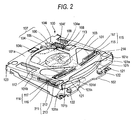
Fig. 2 is a perspective view of the player in which a disk cartridge is inserted in the cartridge holder; -
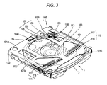
Fig. 3 is a perspective view of the player in which the cartridge holder is in a recording and playing position; -
Fig. 4 is a plan view of the player viewed from the rear side thereof; -
Fig. 5 is a disassembled perspective view of the player; -
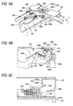
Fig. 6A is a perspective view of an eject lever section in an unlocked state; -
Fig. 6B is a plan view of the eject lever section in the unlocked state; -
Fig. 6C is a side view of the eject lever section in the unlocked state; -
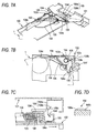
Fig. 7A is a perspective view of the eject lever section in a locked state; -
Fig. 7B is a plan view of the eject lever section in the locked state; -
Fig. 7C is a side view of the eject lever section in the locked state; -
Fig. 7D is a sectional view of an eject-lever lock section; -
Fig. 8A is a side view of a state in which an eject-lever unlock member is engaged with an unlock-member engaging section; -
Fig. 8B is a side view of a state in which the eject-lever unlock member is disengaged from the unlock-member engaging section; -
Fig. 8C is a side view of a state in which the unlock-member engaging section is lifted by the eject-lever unlock member; -
Fig. 9A is a perspective view of a state in which an eject lever is unlocked and slightly return-rotates; -
Fig. 9B is a plan view of the state of the eject lever; -
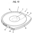
Fig. 10 is a perspective view of the disk cartridge; -
Fig. 11 is a perspective view of the disk cartridge viewed from the bottom surface side thereof; -
Fig. 12 is an enlarged view of a popup spring section; -
Fig. 13 is a sectional view of the popup spring section taken along line A-A inFig. 12 ; -
Fig. 14 is a side view of a state in which a cabinet lid is pushed up by a popup spring; -
Fig. 15 is a front view of the state in which the cabinet lid is pushed up by the popup spring; -
Fig. 16 is a side view of a state in which the cabinet lid is closed and the popup spring bends; -
Fig. 17 is a perspective view of the cartridge holder viewed from a first side in which a cartridge insertion guide projection is provided; -
Fig. 18 is a bottom view of the disk cartridge showing an insertion process of the disk cartridge; -
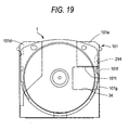
Fig. 19 is a bottom view of the disk cartridge in a housed state; -
Fig. 20 is a sectional view of a spindle motor; -
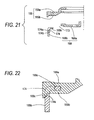
Fig. 21 is a disassembled sectional view of main parts of a rotor and a disk table of the spindle motor; -
Fig. 22 is a sectional view of a state in which the main parts of the rotor and the disk table of the spindle motor are combined; -
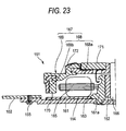
Fig. 23 is a sectional view of a spindle motor according to a second embodiment of the present invention; -
Fig. 24 is a disassembled sectional view of main parts of a rotor and a disk table of the spindle motor according to the second embodiment; -
Fig. 25 is a sectional view of a state in which the main parts of the rotor and the disk table of the spindle motor according to the second embodiment are combined; -
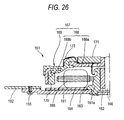
Fig. 26 is a sectional view of a spindle motor according to a third embodiment of the present invention; -
Fig. 27 is a disassembled sectional view of main parts of a rotor and a disk table of the spindle motor according to the third embodiment; -
Fig. 28 is a sectional view of a state in which the main parts of the rotor and the disk table of the spindle motor according to the third embodiment are combined; -
Fig. 29 is a. sectional view of a spindle motor according to a fourth embodiment of the present invention; -
Fig. 30 is a disassembled sectional view of main parts of a rotor and a disk table of the spindle motor according to the fourth embodiment; -
Fig. 31 is a sectional view of a state in which the main parts of the rotor and the disk table of the spindle motor according to the fourth embodiment are combined; -
Fig. 32 is a sectional view of a thread motor; -
Fig. 33 is a sectional view of a rotor of the thread motor; -
Fig. 34 is a sectional view of a spindle motor in the past; -
Fig. 35 is an enlarged view of a main part of the spindle motor; and -
Fig. 36 is a sectional view of a state in which a rotor and a disk table of the spindle motor are separated. - Embodiments of the present invention will be hereinafter explained in detail.
-
Fig. 1 is a perspective view of aplayer 100 in which acartridge holder 101 is present in a cartridge inserting and removing position.Fig. 2 is a perspective view of theplayer 100 in which adisk cartridge 1 is housed in thecartridge holder 101.Fig. 3 is a perspective view of theplayer 100 in which thecartridge holder 101 is in a recording and playing position.Fig. 4 is a plan view of theplayer 100 viewed from the rear surface side thereof.Fig. 5 is a disassembled view of theplayer 100. - The player 100 includes the cartridge holder 101 in which the disk cartridge 1 is inserted and held, a chassis 102 that supports the cartridge holder 101 to be movable between the cartridge inserting and removing position and the recording and playing position, a recording and playing mechanism 103 provided in the chassis 102 and including an optical pickup, a spindle motor, and a thread motor that perform recording and playing of a disk in the disk cartridge 1, a disk cartridge eject mechanism 107 including an eject lever 104 that is provided in the chassis 102 to be rotatable in inserting and removing directions of the disk cartridge 1 (hereinafter simply referred to as "rotatable") and movable in directions toward and away from the chassis 102 and is pushed by the disk cartridge 1 inserted into the cartridge holder 101 and rotates, an eject spring 105 that gives a rotation force in a disk cartridge ejecting direction and a force in a direction for pressing against the upper surface of the chassis 102 to the eject lever 104, and a damper spring 106 that gives a braking force to the eject lever 104, an eject-lever lock section 108 that locks (positions and engages) the eject lever 104, which is rotated by the insertion of the disk cartridge 1, in the chassis 102, and an eject-lever unlock section 109 that unlocks (disengages) the eject lever 104 locked by the eject-lever lock section 108 when the cartridge holder 101 is rotated from the recording and playing position to the cartridge inserting and removing position.
- The eject-
lever unlock section 109 is provided in thecartridge holder 101. When thecartridge holder 101 is rotated from the recording and playing position to the cartridge inserting and removing position, the eject-lever unlock section 109 pushes up theeject lever 104 and unlocks theeject lever 104 locked by the eject-lever lock section 108. - As shown in
Fig. 1 andFigs. 6A to 6C , when thedisk cartridge 1 is inserted into thecartridge holder 101 in a state in which thecartridge holder 101 is present in the cartridge inserting and removing position (a state in which thecartridge holder 101 is inclined at a predetermined inclination angle with respect to the chassis 102), a pressedsection 104c of theeject lever 104 is pushed by the front surface of thedisk cartridge 1. Theeject lever 104 rotates around ashaft section 104i in the clockwise direction against a spring force of theeject spring 105. - As shown in
Fig. 2 andFigs. 7A to 7C , when thedisk cartridge 1 is inserted to a predetermined position of thecartridge holder 101, a lockedsection 104e of theeject lever 104 surmounts the eject-lever lock section 108 and engages with oneend 108 of the eject-lever lock section 108. Consequently, the return rotation of theeject lever 104 is prevented. - As shown in
Fig. 7D , the oneend 108a of the ejectlevel lock section 108 is formed as a substantially vertical surface. The lockedsection 104e of theeject lever 104 surely engages with the oneend 108a. On the other hand, theother end 108b of the eject-lever lock section 108 is formed as an inclined surface. The lockedsection 104e of theeject lever 104 surmounts the eject-lever lock section 108. - When the
disk cartridge 1 is inserted to move thecartridge holder 101 to the recording and playing position as shown inFig. 3 , as shown inFig. 8A , anouter side surface 109c of a ratchet-like pawl 109b of the eject-lever lock section 109 comes into contact with the tip of an unlock-member engaging section 104f of theeject lever 104, the eject-lever unlock section 109 bends in the portion of anarm section 109a, and thepawl 109b moves in a direction in which thepawl 109b escapes from the unlock-member engaging section 104f. When thepawl 109b passes the unlock-member engaging section 104f, as shown inFig. 8B , thepawl 109b returns to an original position thereof and enters the lower surface side of the unlock-member engaging section 104f to be engageable with the lower surface of the unlock-member engaging section 104f. In this state, recording and playing of an optical disk are performed. - When the
cartridge holder 101 is moved to the cartridge inserting and removing position after the recording and playing are finished, as shown inFig. 8C , theeject lever 104 is lifted by thepawl 109b of the eject-lever unlock section 109. Theeject lever 104 locked by the eject-lever lock section 108 is disengaged (unlocked). Theeject lever 104 return-rotates in the counterclockwise direction with theeject spring 105. During the return rotation, theeject lever 104 is given with a braking force by thedamper spring 106 and slowly rotates to push out thedisk cartridge 1 from thecartridge holder 101. - The recording and
playing mechanism 103 includes aspindle motor 151, anoptical pickup 152, athread motor 153, and atransmission gear group 154 that transmits the rotation of thethread motor 153 to theoptical pickup 152. - When the
disk cartridge 1 is inserted into thecartridge holder 101 and moved to the recording and playing position, the optical disk in thecartridge holder 101 is chucked on thespindle motor 151 in thecartridge holder 101 and driven to rotate. Recording and playing of the optical disk are performed while theoptical pickup 152 is moved in a radial direction of the optical disk by thethread motor 153 and thetransmission gear group 154. - As shown in
Fig. 20 , thespindle motor 151 includes atubular bearing section 161a provided in astator substrate 161, a bearing 162 attached to the inner periphery of thebearing section 161 a, awiring board 164 placed on thestator substrate 161 with thetubular bearing section 161a inserted in acenter hole 163, an iron-core coil 165 attached to the outer periphery of thetubular bearing section 161a, and arotor assembly 167 rotatably attached with the tip of arotating shaft 166 inserted in thebearing 162. Therotor assembly 167 includes arotor 168 and a disk table 169 of synthetic resin outsert-molded in therotor 168. - A
rotor magnet 170 forming a pair with the iron-core coil 165 is attached to the inner surface of therotor 168. A chuckingmagnet 171 that magnetically chucks ahub 22 of a disk-like recording medium 2 and a centeringspring 172 that performs centering of the disk-like recording medium 2 are attached to the disk table 169. - As shown in a disassembled sectional view in
Fig. 21 , therotor assembly 167 includes therotor 168 made of metal and the disk table 169 of synthetic resin outsert-molded in therotor 168. - The
rotor 168 includes a substantially circulartop surface section 168a and atubular skirt section 168b arranged at apredetermined space 173 from the outer periphery of thetop surface section 168a. At the upper end of thetubular skirt section 168b, a ring-like flange section 168c is formed by bending the upper end to the inner side at a substantially right angle. - In the bent portion at the upper end of the
skirt section 168b, first resin lead-inholes 174 are formed. The first resin lead-inholes 174 are provided in a row at predetermined intervals in the peripheral direction of thetubular skirt section 168b. - The disk table 169 includes a table
main body section 169a located on the outer surface side of therotor 168 and a rotor-inner-surface superimposing section 169b located on the inner surface side of therotor 168. - The disk table 169 is outsert-molded by, after positioning and arranging the
top surface section 168a and thetubular skirt section 168b of therotor 168 in a molding die at apredetermined space 173, injecting molten resin into the molding die. As shown inFig. 22 , the inner surface of the tablemain body section 169a and the outer surface of the rotor-inner-surface superimposing section 169b are coupled by thespace 173 and the first resin lead-inholes 174, whereby the coupling of therotor 168 and the disk table 169 is reinforced. As shown inFig. 21 , at the lower end side of the peripheral edge of the resin lead-inholes 174, the inner surface side is formed as athin section 174a by forming arecess 174a on the outer surface side. This reinforces the tablemain body section 169a by increasing the thickness of asection 169c corresponding to therecess 174a of the tablemain body section 169a as shown inFig. 22 by leading a part of the resin into therecess 174a when the disk table 169 is insert-molded. -
Figs. 23 to 25 show another (second) embodiment for reinforcing the coupling of therotor 168 and the disk table 169. In this embodiment, agroove 175 for leading in a part of the synthetic resin forming the disk table 169 is formed in the outer peripheral surface of theskirt section 168b of therotor 168. When the disk table 169 is outsert-molded, apart 169d of the resin on the tablemain body section 169a side is led into thegroove 175, whereby the coupling of therotor 168 and the disk table 169 is reinforced. In the second embodiment, the other components are the same as those in the first embodiment. Thus, the components identical with those in the first embodiment are denoted by the identical reference numerals and signs and redundant explanation is omitted. -
Figs. 26 to 28 show still another (third) embodiment for reinforcing the coupling of therotor 168 and the disk table 169. In this embodiment, the width of the ring-like flange section 168c provided at the upper end of thetubular skirt section 168b is set slightly larger than that in the first embodiment and second resin lead-inholes 176 are formed in theflange section 168c. - When the disk table 169 is outsert-molded in the
rotor 168, the inner surface of the tablemain body section 169a and the outer surface of the rotor-inner-surface superimposing section 169b are coupled by the second resin lead-inholes 176, whereby the coupling of therotor 168 and the disk table 169 is reinforced. In the third embodiment, the other components are the same as those in the first embodiment. Thus, the components identical with those in the first embodiment are denoted by the identical reference numerals and signs and redundant explanation is omitted. -
Figs. 29 to 31 show still another (fourth) embodiment for reinforcing the coupling of therotor 168 and the disk table 169. This embodiment is a combination of the second and third embodiments. Thegroove 175 for leading in a part of the synthetic resin forming the disk table 169 is formed in the outer peripheral surface of theskirt section 168b of therotor 168 and the second resin lead-inholes 176 are provided in theflange section 168c. In this embodiment, both the effect of the second embodiment and the effect of the third embodiment are realized. In the fourth embodiment, the other components are the same as those in the second and third embodiments. Thus, the components identical with those in the second and third embodiments are denoted by the identical reference numerals and signs and redundant explanation is omitted. - In these embodiments, the
rotor 168 includes the two components, i.e., thetop surface section 168a and thetubular skirt section 168b. However, thetop surface section 168a and thetubular skirt section 168b may be united and a hole for leading in resin corresponding thespace 173 may formed between thetop surface section 168a and thetubular skirt section 168b. - As shown in
Fig. 32 , thethread motor 153 is attached to astator substrate 191 serving as a motor support plate. Thethread motor 153 is attached to thestator substrate 191 with the outer periphery of thestator substrate 191 superimposed on the lower surface of thechassis 102 and suspended from the lower surface of thechassis 102 by ascrew 155 or the like. - The
thread motor 153 includes atubular bearing section 191 a provided in thestator substrate 191, a bearing 192 attached to the inner periphery of thebearing section 191a, awiring board 194 placed on thestator substrate 191 with thetubular bearing section 191a inserted in acenter hole 193, an iron-core coil 195 attached to the outer periphery of thetubular bearing section 191, and arotor 197 rotatably attached with therotating shaft 196 inserted in thebearing 192. Arotor magnet 198 forming a pair with the iron-core coil 195 is provided on the inner surface of therotor 197. - As shown in
Fig. 33 , therotor 197 is formed in a bottomed cylindrical shape by acylindrical section 197a and abottom surface section 197b. Therotor 197 includes a ring-likefirst gear 201 on the outer peripheral surface at the end on thebottom surface section 197b side of thecylindrical section 197a. Therotor 197 includes aflange section 200, which is opposed to the ring-like gear 201 at a predetermined space, at the end on the opposite side of thebottom surface section 197b side of thecylindrical section 197a. - The ring-like
first gear 201 is integrally molded on the outer surface of therotor 197 by outsert or the like or is attached to the outer surface of therotor 197 by being fit therein. Theflange section 200 is formed by bending the end on an opening side of therotor 197 to the outer side at a substantially right angle or is formed on the outer surface of therotor 197 by outsert or the like. - The rotation of the
rotor 197 of thethread motor 153 is transmitted to theoptical pickup 152 via the ring-likefirst gear 201 and thetransmission gear group 154 explained later. - A motor-
drop preventing section 140 is a section for preventing thethread motor 153 from dropping from thechassis 102 because of, for example, loosening of thescrew 155. As shown inFigs. 32 and 33 , the motor-drop preventing section 140 is formed in a substantially L shape by avertical piece 141 formed substantially vertically along the outer peripheral surface of thethread motor 153 on the lower surface side of thechassis 103 and ahorizontal piece 142 formed by bending the tip of thevertical piece 141 at a substantially right angle toward the center of the thread motor. The tip of thehorizontal piece 142 is inserted between a ring-like gear 199 provided on the outer peripheral surface of therotor 197 and theflange section 200. - The
vertical piece 141 may have elasticity and may be bent to permit thehorizontal piece 142 to escape such that thehorizontal piece 142 does not interfere with the attachment of thethread motor 153 to thechassis 102. - The motor-
drop preventing section 140 is formed by cutting and raising thechassis 102 or is formed by outsert-molding in thechassis 102. - The motor-
drop preventing section 140 has the structure described above. When thethread motor 153 moves in a direction in which thethread motor 153 drops from thechassis 102, thehorizontal piece 142 of the motor-drop preventing section 140 engages with theflange section 200 of therotor 197, prevents further movement of thethread motor 153 in the drop direction, and prevents thethread motor 153 from dropping from thechassis 102. - The
transmission gear group 154 transmits the rotation of thethread motor 153 to theoptical pickup 152 side and causes theoptical pickup 152 to travel. As shown inFig. 5 , thetransmission gear group 154 includes asecond gear 202 that meshes with the ring-like gear (hereinafter referred to as first gear) 201 provided on the outer peripheral surface of therotor 197, athird gear 203 formed coaxially with thesecond gear 202 on the upper surface (a surface opposed to the chassis 102) of thesecond gear 202, afourth gear 204 that meshes with thethird gear 204, and afifth gear 205 that meshes with thefourth gear 204. Thefifth gear 205 is attached to the end of alead screw 185 of theoptical pickup 152. - A flat gear (a spur gear) is used as the
second gear 202. A worm gear is used as thethird gear 203. A shaft-like worm gear is used as thefourth gear 204. A worm gear is used as thefifth gear 205. - In the
fourth gear 204, oneend 204a and theother end 204b are formed as reverse screws with the center in the length direction as a boundary. Thethird gear 203 meshes with the oneend 204a and thefifth gear 205 meshes with theother end 204b. Thethread motor 153 rotates thelead screw 185 via thefirst gear 201, thesecond gear 202, thethird gear 203, thefourth gear 204, and thefifth gear 205 to thereby cause theoptical pickup 152 to travel. - As described above, the ring-like
first gear 201 is provided on the outer peripheral surface of therotor 197 of thethread motor 153 and the flatsecond gear 202 is meshed with thefirst gear 201. Thus, it is possible to reduce the thickness of the thread motor and reduce a size and the thickness of a mechanical assembly compared with the thread motor in which the first gear is attached to be superimposed on the bottom surface of the rotor. - As shown in
Fig. 5 , theoptical pickup 152 includes an object-lens driving device 181 and a movingstand 182 that moves the object-lens driving device 181 in a radial direction of the disk-like recording medium 2 chucked on the disk table 169. - The moving
stand 182 includes afirst bearing section 183 and asecond bearing section 184. Thelead screw 185 is attached to thefirst bearing section 183. Aguide section 186 is attached to thesecond bearing section 184. - The
lead screw 185 is rotatably supported by a pair ofbearings 187 on the lower surface side of thechassis 102. Theguide section 186 is formed integrally with thechassis 102 by outsert-molding. - The
optical pickup 152 rotates thelead screw 185 to thereby move in the radial direction of the optical disk on the disk table 169 and performs recording and playing of the optical disk. Theoptical pickup 152 is capable of performing not only playing but also recording. - As described above, the disk
cartridge eject mechanism 107 is a mechanism for ejecting thedisk cartridge 1 from thecartridge holder 101 after recording and playing are finished. The diskcartridge eject mechanism 107 includes theeject lever 104, theeject spring 105, and thedamper spring 106. - As shown in
Figs. 9A and 9B , the diskcartridge eject mechanism 107 including theeject lever 104, theeject spring 105, and thedamper spring 106 is arranged in a space formed by the front surface of thedisk cartridge 1 housed in thecartridge holder 101, the upper surface of thechassis 102, and the lower surface of thecartridge holder 101, i.e., a so-called dead space. - When the
disk cartridge 1 is inserted, theeject lever 104 is pushed by the front surface of a cartridgemain body 3, rotates against a spring force of theeject spring 105, and is locked to be unable to return-rotate by the eject-lever lock section 108 provided in thechassis 102. After recording and playing are finished, when thecartridge holder 101 is moved to the cartridge inserting and removing position, theeject lever 104 is unlocked from the eject-lever lock section 108 by the eject-lever unlock section 109 explained later, return-rotates with the spring force of theeject spring 105, and ejects thedisk cartridge 1 from thecartridge holder 101. - As shown in
Fig. 5 , the eject lever 104 includes a substantially L-shaped base section (a flat main section) 104a superimposed on the upper surface of the chassis 102, a pressed section 104c provided on one end side of the base section 104a via an arm section 104b and pressed by a front surface 3a of the cartridge main body 3 of the disk cartridge 1, a bearing hole 104d provided in the center of the base section 104a, the locked section 104e that is provided on the other end side of the base section 104a and engages with the eject-lever lock section 108 in a state in which the disk cartridge 1 is completely housed in the cartridge holder 101,the unlock-member engaging section 104f that is provided in an upper position near the locked section 104e and with which the eject-lever unlock section 109 provided in the cartridge holder 101 engages when the disk cartridge 1 is moved from the cartridge inserting and removing position to the recording and playing position, a first eject-spring locking section 104g provided at the end on the opposite side of the pressed section 104c of the arm section 104b, and a damper-spring contact section 104h that is provided in the center of the base section 104a and comes into contact with an end 106b of the damper spring 106 explained later when the eject lever 104 rotates a predetermined angle. - The
eject lever 104 is attached to the upper surface of thechassis 102 such that the center of thebase section 104a is rotatable by theshaft 104i and it is possible to slightly lift thebase section 104a and the lockedsection 104e from the upper surface of thechassis 102. - A helical tension spring is used as the
eject spring 105. Oneend 105a of theeject spring 105 is locked to the first eject-spring locking section 104g provided in theeject lever 104 and theother end 105b thereof is locked to a second eject-spring locking section 102a provided on the upper surface of thechassis 102. Theeject spring 105 gives a rotating force in a disk cartridge ejecting direction to theeject lever 104 and gives a force for pressing thebase section 104a of theeject lever 104 against the upper surface of thechassis 102 to theeject lever 104. The eject-lever lock section 108 is arranged near a position to which a line connecting the first eject-spring locking section 104g and the second eject-spring locking section 102a is extended. - The
damper spring 106 is a spring that prevents, when theeject lever 104 return-rotates a predetermined angle with the spring force of theeject spring 105, thedisk cartridge 1 from dropping from thecartridge holder 101 by giving a braking force to theeject lever 104 to lessen rotating speed of theeject lever 104. A helical torsion spring is used as thedamper spring 106. - The
damper spring 106 is attached to the outer periphery of theshaft section 104i and oneend 106a thereof is engaged with a damper-spring locking section 102b provided in thechassis 102. Theother end 106b of thedamper spring 106 is inserted in a damper-spring-end receiving groove 102c provided in thechassis 102. - As shown in
Fig. 7B , in a state in which theeject lever 104 is locked by the eject-lever lock section 108, theother end 106b of thedamper spring 106 is in contact with the end of the receivinggroove 102c. When theeject lever 104 return-rotates a predetermined angle in the direction for ejecting the disk cartridge with the spring force of theeject spring 105, as shown inFig. 6B , the damper-spring contact section 104h of theeject lever 104 comes into contact with theother end 106b of thedamper spring 106, twists thedamper spring 106, causes thedamper spring 106 to generate a spring force in a direction opposite to the direction of the spring force of theeject spring 105, and gives a braking force to theeject lever 104. - The disk
cartridge eject mechanism 107 has the structure described above. As shown inFig. 1 , when thedisk cartridge 1 is inserted into thecartridge holder 101 in the cartridge inserting and removing position (a state in which thecartridge holder 101 is inclined a predetermined inclination angle θ with respect to the chassis 102), the pressedsection 104c is pushed by the front surface of the cartridgemain body 3 and rotates against the spring force of theeject spring 105. When thedisk cartridge 1 is completely housed in thecartridge holder 101, as shown inFig. 2 , the lockedsection 104e on the outer side surface of the flatmain section 104a of theeject lever 104 engages with the eject-lever lock section 108 and is locked to be unable to return-rotate. As shown inFig. 3 , even when thecartridge holder 101 is moved to the recording and playing position, theeject lever 104 maintains thecartridge holder 101 to be unable to return-rotate. - After the recording and playing are finished, when the
cartridge holder 101 is rotated from the recording and playing position to the cartridge inserting and removing position, as shown inFigs. 9 and10 , theeject lever 104 is unlocked by the eject-lever unlock section 109. Therefore, theeject lever 104 return-rotates with the spring force of theeject spring 105 and ejects thedisk cartridge 1 from thecartridge holder 101. In this case, the return rotation of theeject lever 104 is lessened by thedamper spring 106 to prevent thedisk cartridge 1 from dropping from thecartridge holder 101 without being stopped when thedisk cartridge 1 is pushed out. - The eject-
lever unlock section 109 is a section that unlocks, when thecartridge holder 102 is rotated from the recording and playing position to the cartridge inserting and removing position, theeject lever 104 locked by the eject-lever lock section 108, causes theeject lever 104 to return-rotate with the spring force of theeject spring 105, and ejects thedisk cartridge 1 from thecartridge holder 101. The eject-lever unlock section 109 is also called a ratchet member because of functions thereof. - As shown in
Figs. 6A to 6C toFigs. 8A to 8C , the eject-lever unlock section 109 is provided in thecartridge holder 101. The eject-lever unlock section 109 engages thecartridge holder 101 on the lower surface side of the unlock-member engaging section 104f provided in theeject lever 104 while thecartridge holder 101 is moved from the cartridge inserting and removing position to the recording and playing position. When thecartridge holder 101 is moved from the recording and playing position to the cartridge inserting and removing position, the eject-lever unlock section 109 slightly lifts thebase section 104a and the lockedsection 104e from the upper surface of thechassis 102 via the unlock-member engaging section 104f and disengages the lockedsection 104e and the eject-lever lock section 108. - As shown in
Figs. 8A to 8C , the eject-lever unlock section 109 includes thearm section 109a having elasticity (flexibility) and thepawl 109b formed by bending the tip of thearm section 109a at an acute angle with respect to thearm section 109a. - While the
cartridge holder 101 is moved from the cartridge inserting and removing position to the recording and playing position, theinclined surface 109c of thepawl 109b of the eject-lever unlock section 109 comes into contact with the side of the unlock-member engaging section 104f and moves to escape and theinclined surface 109c of thepawl 109b and the side of the unlock-member engaging section 104f are disengaged. Then, thepawl 109b returns to the original position and thetip 109d of thepawl 109b enters the lower surface side of the unlock-member engaging section 104f. - The eject-
lever unlock section 109 is formed by cutting and raising a part of thecartridge holder 101 or by attaching a member formed separately from thecartridge holder 101 to thecartridge holder 101. - Actions of the eject-
lever unlock section 109 are explained. As shown inFig. 1 , when thedisk cartridge 1 is inserted into thecartridge holder 101 present in the cartridge inserting and removing position, as described above, the pressedsection 104c provided at one end of theeject lever 104 is pushed by the front surface of thedisk cartridge 1. Theeject lever 104 rotates against the spring force of theeject spring 104. The lockedsection 104e provided at the other end of theeject lever 104 engages with the eject-lever lock section 108 provided in thechassis 102 and theeject lever 104 is locked to be unable to return-rotate. In this state, as shown inFig. 7C , the unlock-member engaging section 104f provided near the upper part of the lockedsection 104e of theeject lever 104 is located substantially right below the eject-lever unlock section 109 provided in thecartridge holder 101. - When the
cartridge holder 101 is rotated toward the recording and playing position, as shown inFig. 8A , theinclined surface 109c of thepawl 109b of the eject-lever unlock section 109 comes into contact with the side of the unlock-member engaging section 104f of theeject lever 104 and is pressed by the side. Thearm section 109a bends and thepawl 109b moves in a direction of escape from the side of the unlock-member engaging section 104f. - When the
cartridge holder 102 moves close to the recording and playing position, theinclined surface 109c of thepawl 109b and the side of the unlock-member engaging section 104f are disengaged. As shown inFig. 8B , thepawl 109b return-moves because of the elasticity of thearm section 109a and thetip 109d of thepawl 109b enters on the lower surface of the unlock-member engaging section 104f. In this state, recording and playing of a disk are performed. - After the recording and playing are finished, when the
cartridge holder 101 is rotated toward the cartridge inserting and removing position, as shown inFig. 8C , thetip 109d of thepawl 109b of the eject-lever unlock section 109 engages with the lower surface of the unlock-member engaging section 104f. Thebase section 104a is lifted via the unlock-member engaging section 104f. As shown inFigs. 9A and 9B , the lockedsection 104e of theeject lever 104 and the eject-lever lock section 108 provided in thechassis 102 are disengaged. Theeject lever 104 rotates with the spring force of theeject spring 105 and pushes out thedisk cartridge 1 from thecartridge holder 102. -
Fig. 10 is a perspective view of thedisk cartridge 1 viewed from an upper half side.Fig. 11 is a perspective view of thedisk cartridge 1 viewed from a lower half side. - The
disk cartridge 1 includes the disk-like recording medium 2 such as an optical disk and the cartridgemain body 3 that rotatably houses the disk-like recording medium 2 in a circular disk housing section and includes a recording and playingopening 34 that exposes a part of the disk-like recording medium 2 to the outside. Thedisk cartridge 1 is a so-called shutter-less disk cartridge that does not include a shutter for opening and closing the recording and playingopening 34. - As shown in
Fig. 11 , the disk-like recording medium 2 is formed by attaching the chuckinghub 22 in the center of theoptical disk 21 in which software for a game or the like is recorded. Theoptical disk 21 is formed in a diameter as small as about 50 mm. The chuckinghub 22 is formed of magnetic metal such as stainless steel that is attracted by a magnet. - The cartridge
main body 3 is formed by joining peripheral walls of upper andlower halves main body 3, thefront surface 3a (a side on an end side of insertion in the player explained later) is formed as an arcuate surface (a semicircular surface) having a curvature radius substantially the same as that of theoptical disk 21. First andsecond sides front surface 3a are formed as flat surfaces parallel to each other. Arear surface 3d opposed to thefront surface 3a is formed as a curved surface gently continuing to the first andsecond sides - A driving
opening 33 that exposes thehub 22 of the disk-like recording medium 2 to the outside is provided in the center of thelower half 32. A recording and playingopening 34 that exposes an information recording surface of theoptical disk 21 of the disk-like recording medium 2 is provided from the vicinity of the drivingopening 33 to thesecond side 3c. - As shown in
Fig. 10 , thedisk cartridge 1 includes a first lateral-pressure releasing recess 41 in thefirst side 3b of the cartridgemain body 3. When thedisk cartridge 1 is completely housed in thecartridge holder 102, aprojection 213 of a cartridge-drop preventing member 211 provided in afirst side plate 101b (seeFig. 1 ) of thecartridge holder 101 explained next is fit in therecess 41. Therecess 41 brings theprojection 213 into a state of noncontact with thefirst side 3b of the cartridgemain body 3 of thedisk cartridge 1 to remove a lateral pressure applied to thecartridge holder 102 by the cartridge-drop preventing member 211. - As shown in
Fig. 11 , thedisk cartridge 1 includes aguide groove 42 and a second lateral-pressure releasing recess 43 in thesecond side 3c of the cartridgemain body 3. When thedisk cartridge 1 is inserted into thecartridge holder 101, a cartridgeinsertion guide projection 214 provided in asecond side plate 101c (seeFig. 17 ) of thecartridge holder 101 enters theguide groove 42 and guides the insertion of thedisk cartridge 1. When thedisk cartridge 1 is completely housed in thecartridge holder 101, the cartridgeinsertion guide projection 214 is fit in thesecond recess 43. Thesecond recess 43 brings theprojection 214 into a state of noncontact with thesecond side 3c of the cartridgemain body 3 of thedisk cartridge 1 and removes a lateral pressure applied to thecartridge holder 101 by theprojection 214 for cartridge insertion guide. Positioning reference holes 50 in which cartridge positioning reference pins 122 provided in thechassis 102 are fit are provided near therear surface 3d side of the lower surface of the cartridgemain body 3. - The
hub 22 of the disk-like recording medium 2 is magnetically chucked on the disk table of the player via the drivingopening 33. Information is recorded in and reproduced from theoptical disk 21 of the disk-like recording medium 2 by theoptical pickup 152 via the recording and playingopening 34. - As shown in
Fig. 5 , thecartridge holder 101 includes a substantially square upper surface plate (top surface plate) 101a, the left and right side plates (hereinafter referred to as first and second side plates) 101b and 101c formed by bending both the left and right sides of theupper surface plate 101a downward at a substantially right angle, a pair of first and secondcartridge support sections second side plates disk cartridge 1 and tongue-like third and fourthcartridge support sections cartridge support section 101e at a predetermined space, and receivingsurface sections cartridge support sections port 101n for thedisk cartridge 1 and ahousing section 101p extending to the inserting and removingport 101n are formed by the upper surface plate 10 la, the first andsecond side plates cartridge support sections - The eject-
lever unlock section 109 is provided in a position of theupper surface plate 101a of thedisk cartridge 1 located in an upper part in a space in which the diskcartridge eject mechanism 107 is arranged. - The eject-
lever unlock section 109 is formed by cutting and raising a part of theupper surface plate 101a of thedisk cartridge 1. - In the center of the
upper surface plate 101a, ahexagonal opening 111 is punched out in order to reduce the weight of theupper surface plate 101a. On both the left and right sides of theopening 111 of theupper surface plate 101 a, a pair of first andsecond leaf springs upper surface plate 101a. The first andsecond leaf springs housing section 101p. The first andsecond leaf springs disk cartridge 1 inserted in thehousing section 101p and press thedisk cartridge 1 against the first to fourthcartridge support sections 101d to 101g. - Further on the front end side (the inserting and removing
port 101n side) than theopening 111 of theupper surface plate 101a, a pair of third andfourth leaf springs upper surface plate 101a. - As shown in
Fig. 12 in enlargement, each of the third andfourth leaf springs spring section 117 for cartridge pressing (hereinafter referred to as cartridge pressing spring) of a thin and long plate shape branched from one side of thepopup spring 116 and extending in parallel to thepopup spring 116. Width W1 of thepopup spring 116 is formed larger than width W2 of thecartridge pressing spring 117. - The
popup spring 116 is formed in a so-called frame shape by a hollow-outsection 118 extending in a length direction. Abeam section 119 is provided in the hollow-outsection 118. Thebeam section 119 is provided near a base portion of thecartridge pressing spring 117, i.e., a portion where thecartridge pressing spring 117 is branched from thepopup spring 116. - A
base section 116a of thepopup spring 116, abase section 117a of thecartridge pressing spring 117, and abase section 118a of the hollow-outsection 118 are formed in a curved shape to prevent stresses generated when thepopup spring 116 and thecartridge pressing spring 117 bend from concentrating on one place. As shown inFig. 13 , thepopup spring 116 is bent in a gentle curved shape in thebase section 116a to prevent a stress generated when thepopup spring 116 bends from concentrating on one place. Thecartridge pressing spring 117 extends substantially in parallel to theupper surface plate 101a or parallel to thepopup spring 116 from the middle of thepopup spring 116. - As shown in
Figs. 14 and15 , atip 116b of thepopup spring 116 comes into contact with aninner surface 110a of thecabinet lid 110 that rotates thecartridge holder 101 between the recording and playing position and the cartridge inserting and removing position. - When the
disk cartridge 1 is inserted in thecartridge holder 101 1 and thecabinet lid 110 is closed, as shown inFig. 3 , thecartridge holder 101 moves to the recording and playing position. As shown inFig. 16 , thetip 116b of thepopup spring 116 is pushed by theinner surface 110a of thecabinet lid 110 and thepopup spring 116 bends to thedisk cartridge 1 side. When thepopup spring 116 bends, atip 117b of thecartridge pressing spring 117 branched from one side of thepopup spring 116 comes into contact with the upper surface of thedisk cartridge 1 and presses the disk-cartridge 1 against the cartridge support section of thecartridge holder 101. At this point, a force in a twisting direction acts on thepopup spring 116 according to a reaction of thecartridge pressing spring 117. However, the force in the twisting direction is dispersed to the entire area of thepopup spring 116 by thebeam section 119 and the like provided in thepopup spring 116. Thepopup spring 116 is prevented from plastically deforming in the twisting direction. - As described above, recording and playing are performed in a state in which the
disk cartridge 1 is pressed against the first to fourthcartridge support sections 101d to 101g by spring forces of the tips of the first andsecond leaf springs popup spring 116 and thecartridge pressing spring 117 of the third andfourth leaf springs cabinet lid 110 is opened after the recording and playing are finished, thecartridge holder 101 rotates to the cartridge inserting and removing position. As shown inFig. 14 , a predetermined clearance C is formed between thecartridge holder 101 and thecabinet lid 110 by thepopup spring 116, the closure of the cartridge inserting and removingport 101n of thecartridge holder 101 by thefront surface plate 110b of thecabinet lid 110 is released, and the cartridge inserting and removingport 101n is opened. - As shown in
Fig. 1 , the cartridge-drop preventing member 211 that gives a braking force for the ejection of thedisk cartridge 1 by theeject spring 105 and prevents thedisk cartridge 1 from dropping from thecartridge holder 101 is cut and raised in thefirst side plate 101b of thecartridge holder 101. The cartridge-drop preventing member 211 includes anelastic piece 212 extending toward the cartridge inserting and removingport 101n side of thecartridge holder 102 and theprojection 213 that is provided at the tip of theelastic piece 212 and comes into slide contact with thefirst side 3b of thedisk cartridge 1 when thedisk cartridge 1 is ejected. When thedisk cartridge 1 is completely housed in thecartridge holder 101, theprojection 213 fits in the lateral-pressure releasing recess 41 provided in thefirst side 3b of thedisk cartridge 1, comes into a state of noncontact with thefirst side 3b, and releases a lateral pressure. - As shown in
Fig. 17 , at the end on the cartridge inserting and removingport 101n of thesecond side plate 101c of thecartridge holder 101, the cartridgeinsertion guide projection 214 projecting into thecartridge housing section 101p is provided. The cartridgeinsertion guide projection 214 is cut and raised in substantially the center in the thickness direction of thesecond side plate 101c of thecartridge holder 101. - As shown in
Fig. 17 , when thedisk cartridge 1 is inserted in thecartridge holder 101 in a normal posture, the cartridgeinsertion guide projection 214 is led into theguide groove 42 provided in the oneside 3c of thedisk cartridge 1. When thedisk cartridge 1 is inserted to a predetermined position, the cartridgeinsertion guide projection 214 is located in the second lateral-pressure releasing recess 43 provided continuously to the tip of theguide groove 42 and comes into a state of noncontact with thedisk cartridge 1. - When the
disk cartridge 1 is inserted into thecartridge holder 101, the cartridgeinsertion guide projection 214 guides the insertion of thedisk cartridge 1. As shown inFig. 18 , the cartridgeinsertion guide projection 214 prevents theend 101t of the secondcartridge support section 101e of thecartridge holder 101, the thirdcartridge support section 101f, or the like from entering the recording and playingopening 34 of thedisk cartridge 1 to damage the information recording surface of the disk-like recording medium. - When the
disk cartridge 1 is a disk cartridge of the shutter-less type, the recording and playingopening 34 is typically in an opened state. Thus, for example, when thedisk cartridge 1 is inserted into thecartridge holder 101, if a strong push-down force is applied to thedisk cartridge 1 because of some reason, theend 101t of the secondcartridge support section 101e of the cartridge holder, the thirdcartridge support section 101f, or the like enters the recording and playingopening 34. Thus, it is likely that the information recording surface of the disk-like recording medium is scratched by theend 101t of the secondcartridge support section 101e or the like or the outer peripheral surface of the disk-like recording medium in thedisk cartridge 1 overlaps the secondcartridge support section 101e. The cartridgeinsertion guide projection 214 comes into contact with anupper surface 42a of theguide groove 42, regulates the movement in the thickness direction of thedisk cartridge 1, and prevents theend 101t of the secondcartridge support section 101e of thecartridge holder 101, the thirdcartridge support section 101f, or the like from entering the recording and playingopening 34 and scratching the information recording surface of the disk-like recording medium or prevent the outer peripheral surface of the disk-like recording medium from overlapping the thirdcartridge support section 101f. - The cartridge
insertion guide projection 214 acts as a mis-insertion preventing member that prevents mis-insertion of thedisk cartridge 1. When thedisk cartridge 1 is inserted with a wrong side up, the cartridgeinsertion guide projection 214 comes into contact with the side of thedisk cartridge 1 to prevent further insertion of thedisk cartridge 1. When thedisk cartridge 1 is inserted with a wrong side front, the cartridgeinsertion guide projection 214 comes into contact with anend surface 41a of the first lateralpressure release groove 41 of thedisk cartridge 1 to prevent further insertion of thedisk cartridge 1. Mis-insertion of thedisk cartridge 1 can be prevented by the thirdcartridge support section 101f shown inFig. 5 when the cartridgeinsertion guide projection 214 is not provided. However, since the cartridgeinsertion guide projection 214 is provided in a position closer to the cartridge inserting and removingport 101n than the thirdcartridge support section 101f, when thedisk cartridge 1 is mis-inserted, it is possible to prevent further insertion of thedisk cartridge 1 at an earlier stage. - As shown in
Fig. 5 , thechassis 102 is formed by a metal plate in a substantially square shape.Damper attaching sections 131 are provided at four corners of thechassis 102.Dampers 132 of rubber are attached to thedamper attaching sections 131. On the left and right sides of thechassis 102, left andright sidewalls second side plates cartridge holder 101 are provided. On one end sides of the left andright sidewalls sections cartridge holder 101 are provided.Shafts sections holes cartridge holder 101, whereby thecartridge holder 101 is rotatably supported between the cartridge inserting and removing position and the recording and playing position. - The
chassis 102 includes cartridge positioning reference pins 122 that fit in the positioning reference holes 50 of thedisk cartridge 1 via positioning lead-inholes 121 provided in the pair of left and rightcartridge support sections cartridge holder 101 when thecartridge holder 101 is moved to the recording and playing position. - The
chassis 102 includes the eject-lever lock section 108 in a space formed by thefront surface 3a of thedisk cartridge 1 housed in thecartridge holder 101, the upper surface of thechassis 102, and the lower surface of thecartridge holder 101. As shown inFigs. 7A to 7C , when theeject lever 104 is rotated, resisting theeject spring 105, to a position where thedisk cartridge 1 is completely housed in thecartridge holder 101, the eject-lever lock section 108 engages with the lockedsection 104e of theeject lever 104 and locks theeject lever 104 to be unable to return-rotate. The ejectlever lock section 108 is formed by providing an elliptical projection on the upper surface of thechassis 102. As shown inFig. 7D , the oneend 108b of the eject-lever lock section 108 is formed as an inclined surface. The lockedsection 104e of theeject lever 104 surmounts the eject-lever lock section 108. On the other hand, theother end 108a of the ejectlever lock section 108 is formed such that the lockedsection 104e of theeject lever 104 surely engages with theother end 108a. - When the
base section 104a of theeject lever 104 is lifted from thechassis 102 against the spring force of theeject spring 105, the eject-lever lock section 108 is disengaged from the lockedsection 104e. In theeject lever 104 disengaged from the eject-lever lock section 108, thebase section 104a overlaps the eject-lever lock section 108 and rotates. Theeject lever 104 ejects thedisk cartridge 1 from thecartridge holder 101. - As shown in
Figs. 9A and 9B , an eject-lever-lift preventing section 139 that prevents the vicinity of the pressedsection 104c of theeject lever 104 from lifting in a state in which theeject lever 104 is locked by the eject-lever lock section 108 is provided in thechassis 102. - The spindle motor and the
player 101 according to the embodiments have the structure described above. As shown inFig. 14 , if thecabinet lid 110 is opened, thecartridge holder 101 rotates following thecabinet lid 110 and moves to the cartridge inserting and removing position. If thedisk cartridge 1 is inserted in thecartridge holder 101 in the cartridge inserting and removing position, as described above, the center of thefront surface 3a of the cartridgemain body 3 comes into contact with the pressedsection 104c of theeject lever 104 and presses the pressedsection 104c. - When the pressed
section 104c is pressed, theeject lever 104 rotates against the spring force of theeject spring 105, theeject cartridge 1 is completely housed in thecartridge holder 101, and theeject lever 104 is locked to be unable to return-rotate by eject-lever lock section 108. - After the
disk cartridge 1 is housed in thecartridge holder 101, if thecabinet lid 110 is closed, thecartridge holder 101 moves from the cartridge inserting and removing position to the recording and playing position following thecabinet lid 110. - When the
cartridge holder 101 moves from the cartridge inserting and removing position to the recording and playing position, as shown inFig. 8A , the side of the unlock-member engaging section 104f of theeject lever 104 comes into contact with theinclined surface 109c of thepawl 109b of the eject-lever unlock section 109, bends thearm section 109a of the eject-lever unlock section 109, and causes thepawl 109b to move in a so-called escape direction. When the contact of theinclined surface 109c and the side of the unlock-member engaging section 104f is released, the eject-lever unlock section 109 is elastically restored. As shown inFig. 8B , thepawl 109b enters the lower surface side of the unlock-member engaging section 104f to be engageable with the lower surface. - After the recording and playing are finished, if the
cabinet lid 110 is opened, thecartridge holder 101 rotates following thecabinet lid 110 and moves to the cartridge inserting and removing position. When thecartridge holder 101 moves from the cartridge inserting and removing position to the recording and playing position, as shown inFig. 8C , the unlock-member engaging section 104f of theeject lever 104 is lifted by thepawl 109b of the eject-lever unlock section 109 and theeject lever 104 locked by the eject-lever lock unit 108 is unlocked. Theeject lever 104 rotates with the spring force of theeject spring 105 and pushes out thedisk cartridge 1 from thecartridge holder 101. - The spindle motor and the player according to the embodiments have the simple structure in which the resin lead-in holes are provided in the rotor of the spindle motor in the past or the groove is formed in the outer peripheral surface of the skirt section of the rotor. When the disk table is outsert-molded in the rotor, a part of the synthetic resin forming the disk table is led into the other resin lead-in holes and the groove. Consequently, the coupling of the rotor and the disk table is reinforced, lift and wobble of the disk table are surely prevented, and recording and playing of the disk is more surely performed.
- It should be understood by those skilled in the art that various modifications, combinations, sub-combinations, and alterations may occur depending on design requirements and other factors insofar as they are within the scope of the appended claims or the equivalents thereof.
- In so far as the embodiments of the invention described above are implemented, at least in part, using software-controlled data processing apparatus, it will be appreciated that a computer program providing such software control and a transmission, storage or other medium by which such a computer program is provided are envisaged as aspects of the present invention.
- Whilst the embodiments described above each include explicitly recited combinations of features according to different aspects of the present invention, other embodiments are envisaged according to the general teaching of the invention, which include combinations of features as appropriate, other than those explicitly recited in the embodiments described above. Accordingly, it will be appreciated that different combinations of features of the appended independent and dependent claims form further aspects of the invention other than those, which are explicitly recited in the claims.
Claims (5)
- A spindle motor comprising:a rotor made of metal including a substantially circular top surface section and a tubular skirt section arranged at a predetermined space from an outer periphery of the top surface section; anda disk table of synthetic resin outsert-molded in the rotor and including a table main body section located on an outer surface side of the rotor and a rotor-inner-surface superimposing section located on an inner surface side of the rotor, whereinfirst resin lead-in holes are provided in the tubular skirt section and an inner surface of the table main body section located on the outer surface side of the rotor is connected to the rotor-inner-surface superimposing section located on the inner surface side of the rotor through the first resin lead-in holes.
- A player comprising:a rotor made of metal including a substantially circular top surface section and a tubular skirt section arranged at a predetermined space from an outer periphery of the top surface section;a disk table of synthetic resin outsert-molded in the rotor and including a table main body section located on an outer surface side of the rotor and a rotor-inner-surface superimposing section located on an inner surface side of the rotor; anda playing unit that plays a disk mounted on the disk table, whereinfirst resin lead-in holes are provided in the tubular skirt section and an inner surface of the table main body section located on the outer surface side of the rotor is connected to the rotor-inner-surface superimposing section located on the inner surface side of the rotor through the first resin lead-in holes.
- A player comprising:a rotor made of metal including a substantially circular top surface section and a tubular skirt section arranged at a predetermined space from an outer periphery of the top surface section;a disk table of synthetic resin outsert-molded in the rotor and including a table main body section located on an outer surface side of the rotor and a rotor-inner-surface superimposing section located on an inner surface side of the rotor; anda playing unit that plays a disk mounted on the disk table, whereina groove for leading in a part of the synthetic resin forming the disk table is formed in an outer peripheral surface of the skirt section of the rotor.
- A player comprising:a rotor made of metal including a substantially circular top surface section and a tubular skirt section arranged at a predetermined space from an outer periphery of the top surface section;a disk table of synthetic resin outsert-molded in the rotor and including a table main body section located on an outer surface side of the rotor and a rotor-inner-surface superimposing section located on an inner surface side of the rotor; anda playing unit that plays a disk mounted on the disk table, whereinsecond resin lead-in holes are provided in a ring-like flange section formed by bending an upper end of the skirt section inward at a substantially right angle, andan inner surface of the table main body section located on the outer surface side of the rotor is connected to the rotor-inner-surface superimposing section located on the inner surface side of the rotor through the second resin lead-in holes.
- A player according to claim 4, wherein a groove for leading in a part of the resin forming the disk table is formed in an outer peripheral surface of the skirt section of the rotor.
Applications Claiming Priority (1)
| Application Number | Priority Date | Filing Date | Title |
|---|---|---|---|
| JP2006317907A JP5034457B2 (en) | 2006-11-27 | 2006-11-27 | Spindle motor and playback device |
Publications (2)
| Publication Number | Publication Date |
|---|---|
| EP1926100A1 true EP1926100A1 (en) | 2008-05-28 |
| EP1926100B1 EP1926100B1 (en) | 2010-02-03 |
Family
ID=39059623
Family Applications (1)
| Application Number | Title | Priority Date | Filing Date |
|---|---|---|---|
| EP07254345A Not-in-force EP1926100B1 (en) | 2006-11-27 | 2007-11-02 | Spindle motor and disk player |
Country Status (5)
| Country | Link |
|---|---|
| US (1) | US8448199B2 (en) |
| EP (1) | EP1926100B1 (en) |
| JP (1) | JP5034457B2 (en) |
| CN (1) | CN101232221B (en) |
| DE (1) | DE602007004661D1 (en) |
Cited By (1)
| Publication number | Priority date | Publication date | Assignee | Title |
|---|---|---|---|---|
| CN112562745A (en) * | 2021-01-07 | 2021-03-26 | 石家庄书立贸易有限公司 | Anti-pollution optical disc taking and placing equipment |
Families Citing this family (4)
| Publication number | Priority date | Publication date | Assignee | Title |
|---|---|---|---|---|
| US8156513B2 (en) * | 2009-08-21 | 2012-04-10 | Nidec Corporation | Motor and storage disk drive apparatus |
| CN101996656B (en) * | 2009-08-21 | 2013-03-20 | 日本电产株式会社 | Motor, storage disk drive apparatus and motor manufacturing method |
| KR101196628B1 (en) * | 2009-12-21 | 2012-11-02 | 엘지이노텍 주식회사 | Structure of spindle motor |
| CN107168481B (en) * | 2017-05-27 | 2020-05-15 | 苏州浪潮智能科技有限公司 | Fixing device of server information card |
Citations (7)
| Publication number | Priority date | Publication date | Assignee | Title |
|---|---|---|---|---|
| EP0613229A1 (en) * | 1991-11-13 | 1994-08-31 | Seiko Epson Corporation | Brushless dc motor |
| JPH10241273A (en) * | 1997-02-28 | 1998-09-11 | Sankyo Seiki Mfg Co Ltd | Spindle motor |
| US5907206A (en) * | 1996-07-24 | 1999-05-25 | Kabushiki Kaisha Toshiba | Rotor for electric motors |
| US6181671B1 (en) * | 1997-12-05 | 2001-01-30 | Matsushita Electric Industrial Co., Ltd. | Spindle motor and its manufacturing method |
| US6445096B1 (en) * | 2000-11-20 | 2002-09-03 | Olympus Optical Co., Ltd. | Spindle motor |
| JP2004139689A (en) | 2002-10-18 | 2004-05-13 | Sony Corp | Motor and information recording / reproducing apparatus having motor |
| JP2005322318A (en) | 2004-05-10 | 2005-11-17 | Sony Corp | Disc recording and / or playback device |
Family Cites Families (3)
| Publication number | Priority date | Publication date | Assignee | Title |
|---|---|---|---|---|
| US4891567A (en) * | 1987-07-16 | 1990-01-02 | Minebea Co., Ltd. | Brushless DC motor having an outer rotor |
| JPH09153253A (en) * | 1995-11-30 | 1997-06-10 | Matsushita Electric Ind Co Ltd | Disk drive |
| JP2002343016A (en) * | 2001-05-18 | 2002-11-29 | Tokyo Parts Ind Co Ltd | Spindle motor with turntable and its manufacturing method |
-
2006
- 2006-11-27 JP JP2006317907A patent/JP5034457B2/en not_active Expired - Fee Related
-
2007
- 2007-11-02 EP EP07254345A patent/EP1926100B1/en not_active Not-in-force
- 2007-11-02 DE DE602007004661T patent/DE602007004661D1/en active Active
- 2007-11-20 US US11/986,267 patent/US8448199B2/en not_active Expired - Fee Related
- 2007-11-26 CN CN2007101673988A patent/CN101232221B/en not_active Expired - Fee Related
Patent Citations (7)
| Publication number | Priority date | Publication date | Assignee | Title |
|---|---|---|---|---|
| EP0613229A1 (en) * | 1991-11-13 | 1994-08-31 | Seiko Epson Corporation | Brushless dc motor |
| US5907206A (en) * | 1996-07-24 | 1999-05-25 | Kabushiki Kaisha Toshiba | Rotor for electric motors |
| JPH10241273A (en) * | 1997-02-28 | 1998-09-11 | Sankyo Seiki Mfg Co Ltd | Spindle motor |
| US6181671B1 (en) * | 1997-12-05 | 2001-01-30 | Matsushita Electric Industrial Co., Ltd. | Spindle motor and its manufacturing method |
| US6445096B1 (en) * | 2000-11-20 | 2002-09-03 | Olympus Optical Co., Ltd. | Spindle motor |
| JP2004139689A (en) | 2002-10-18 | 2004-05-13 | Sony Corp | Motor and information recording / reproducing apparatus having motor |
| JP2005322318A (en) | 2004-05-10 | 2005-11-17 | Sony Corp | Disc recording and / or playback device |
Cited By (2)
| Publication number | Priority date | Publication date | Assignee | Title |
|---|---|---|---|---|
| CN112562745A (en) * | 2021-01-07 | 2021-03-26 | 石家庄书立贸易有限公司 | Anti-pollution optical disc taking and placing equipment |
| CN112562745B (en) * | 2021-01-07 | 2022-06-14 | 石家庄书立贸易有限公司 | Anti-pollution optical disc taking and placing equipment |
Also Published As
| Publication number | Publication date |
|---|---|
| EP1926100B1 (en) | 2010-02-03 |
| JP2008131846A (en) | 2008-06-05 |
| CN101232221B (en) | 2011-07-13 |
| JP5034457B2 (en) | 2012-09-26 |
| CN101232221A (en) | 2008-07-30 |
| US20080222668A1 (en) | 2008-09-11 |
| US8448199B2 (en) | 2013-05-21 |
| DE602007004661D1 (en) | 2010-03-25 |
Similar Documents
| Publication | Publication Date | Title |
|---|---|---|
| EP1926100B1 (en) | Spindle motor and disk player | |
| US6091584A (en) | Recording medium with a band attached to both sides of a shutter for opening/closing the shutter | |
| KR101139397B1 (en) | Disc drive apparatus, frame, disc drive apparatus set and electronic appliance | |
| CN101202492B (en) | Thread motor and playback device | |
| US5956205A (en) | Disk holding mechanism capable of preventing a disk from undesirable vibration within a disk holder unit | |
| CN102243882A (en) | Disk device | |
| US6816337B1 (en) | Magnetic recording device having a particular frame plate configuration | |
| JP2002237123A (en) | Disc production system | |
| US7739704B2 (en) | Disk apparatus having traverse and spindle cam members and method of operating same | |
| US5805378A (en) | Magnetic disk drive of a structure capable of being lightened in weight | |
| US8561091B2 (en) | Single body type bracket and disk drive device having the same | |
| JP4940906B2 (en) | Playback device | |
| JP4858115B2 (en) | Playback device | |
| US20110258646A1 (en) | Optical pickup supporting device and optical disc apparatus including the same | |
| KR20010012800A (en) | magnetic recording device | |
| US6111727A (en) | Flexible disk comprising a supporting hub for supporting a magnetic recording medium inside of a bottom portion | |
| US6873493B2 (en) | Disk drive having a reinforcing arrangement against an external stress applied thereto | |
| JP4748038B2 (en) | Playback device | |
| JP2916914B2 (en) | Disk drive | |
| US7136259B2 (en) | Frame structure and flexible disk drive having the same | |
| JP4609396B2 (en) | Leaf spring and disk recording and / or reproducing apparatus | |
| US20030053249A1 (en) | Disk drive having a reinforcing arrangement against an external stress applied thereto | |
| US6166878A (en) | Disk drive having the motor core secured via the disk rotating bearing flange to the chassis | |
| JP2000339806A (en) | Disc chucking mechanism | |
| JPS62162271A (en) | Recording or reproducing device |
Legal Events
| Date | Code | Title | Description |
|---|---|---|---|
| PUAI | Public reference made under article 153(3) epc to a published international application that has entered the european phase |
Free format text: ORIGINAL CODE: 0009012 |
|
| AK | Designated contracting states |
Kind code of ref document: A1 Designated state(s): AT BE BG CH CY CZ DE DK EE ES FI FR GB GR HU IE IS IT LI LT LU LV MC MT NL PL PT RO SE SI SK TR |
|
| AX | Request for extension of the european patent |
Extension state: AL BA HR MK RS |
|
| 17P | Request for examination filed |
Effective date: 20080707 |
|
| 17Q | First examination report despatched |
Effective date: 20080813 |
|
| AKX | Designation fees paid |
Designated state(s): DE FR GB |
|
| GRAP | Despatch of communication of intention to grant a patent |
Free format text: ORIGINAL CODE: EPIDOSNIGR1 |
|
| GRAS | Grant fee paid |
Free format text: ORIGINAL CODE: EPIDOSNIGR3 |
|
| GRAA | (expected) grant |
Free format text: ORIGINAL CODE: 0009210 |
|
| AK | Designated contracting states |
Kind code of ref document: B1 Designated state(s): DE FR GB |
|
| REG | Reference to a national code |
Ref country code: GB Ref legal event code: FG4D |
|
| REF | Corresponds to: |
Ref document number: 602007004661 Country of ref document: DE Date of ref document: 20100325 Kind code of ref document: P |
|
| PLBE | No opposition filed within time limit |
Free format text: ORIGINAL CODE: 0009261 |
|
| STAA | Information on the status of an ep patent application or granted ep patent |
Free format text: STATUS: NO OPPOSITION FILED WITHIN TIME LIMIT |
|
| 26N | No opposition filed |
Effective date: 20101104 |
|
| REG | Reference to a national code |
Ref country code: GB Ref legal event code: 746 Effective date: 20120703 |
|
| REG | Reference to a national code |
Ref country code: DE Ref legal event code: R084 Ref document number: 602007004661 Country of ref document: DE Effective date: 20120614 |
|
| PGFP | Annual fee paid to national office [announced via postgrant information from national office to epo] |
Ref country code: FR Payment date: 20121130 Year of fee payment: 6 |
|
| PGFP | Annual fee paid to national office [announced via postgrant information from national office to epo] |
Ref country code: GB Payment date: 20121120 Year of fee payment: 6 |
|
| GBPC | Gb: european patent ceased through non-payment of renewal fee |
Effective date: 20131102 |
|
| REG | Reference to a national code |
Ref country code: FR Ref legal event code: ST Effective date: 20140731 |
|
| PG25 | Lapsed in a contracting state [announced via postgrant information from national office to epo] |
Ref country code: GB Free format text: LAPSE BECAUSE OF NON-PAYMENT OF DUE FEES Effective date: 20131102 Ref country code: FR Free format text: LAPSE BECAUSE OF NON-PAYMENT OF DUE FEES Effective date: 20131202 |
|
| PGFP | Annual fee paid to national office [announced via postgrant information from national office to epo] |
Ref country code: DE Payment date: 20141119 Year of fee payment: 8 |
|
| REG | Reference to a national code |
Ref country code: DE Ref legal event code: R119 Ref document number: 602007004661 Country of ref document: DE |
|
| PG25 | Lapsed in a contracting state [announced via postgrant information from national office to epo] |
Ref country code: DE Free format text: LAPSE BECAUSE OF NON-PAYMENT OF DUE FEES Effective date: 20160601 |