EP1925844A1 - Method and arrangement for machine cooling - Google Patents
Method and arrangement for machine cooling Download PDFInfo
- Publication number
- EP1925844A1 EP1925844A1 EP06124773A EP06124773A EP1925844A1 EP 1925844 A1 EP1925844 A1 EP 1925844A1 EP 06124773 A EP06124773 A EP 06124773A EP 06124773 A EP06124773 A EP 06124773A EP 1925844 A1 EP1925844 A1 EP 1925844A1
- Authority
- EP
- European Patent Office
- Prior art keywords
- temperature
- arrangement
- brake
- fluid
- temperature range
- Prior art date
- Legal status (The legal status is an assumption and is not a legal conclusion. Google has not performed a legal analysis and makes no representation as to the accuracy of the status listed.)
- Withdrawn
Links
- 238000001816 cooling Methods 0.000 title claims abstract description 43
- 238000000034 method Methods 0.000 title claims description 25
- 239000012530 fluid Substances 0.000 claims abstract description 114
- 239000002826 coolant Substances 0.000 claims abstract description 16
- 230000004044 response Effects 0.000 claims description 12
- 230000008569 process Effects 0.000 claims description 6
- 238000006073 displacement reaction Methods 0.000 claims description 5
- 230000003071 parasitic effect Effects 0.000 abstract description 2
- 230000009471 action Effects 0.000 description 7
- 238000002485 combustion reaction Methods 0.000 description 3
- 230000003247 decreasing effect Effects 0.000 description 3
- 230000000694 effects Effects 0.000 description 3
- 239000003921 oil Substances 0.000 description 2
- 238000012545 processing Methods 0.000 description 2
- 230000003111 delayed effect Effects 0.000 description 1
- 230000001419 dependent effect Effects 0.000 description 1
- 238000013461 design Methods 0.000 description 1
- 238000011156 evaluation Methods 0.000 description 1
- 239000000446 fuel Substances 0.000 description 1
- 230000017525 heat dissipation Effects 0.000 description 1
- 239000010720 hydraulic oil Substances 0.000 description 1
- 238000012986 modification Methods 0.000 description 1
- 230000004048 modification Effects 0.000 description 1
- 230000009467 reduction Effects 0.000 description 1
- 230000000979 retarding effect Effects 0.000 description 1
- 230000001960 triggered effect Effects 0.000 description 1
Images

Classifications
-
- F—MECHANICAL ENGINEERING; LIGHTING; HEATING; WEAPONS; BLASTING
- F16—ENGINEERING ELEMENTS AND UNITS; GENERAL MEASURES FOR PRODUCING AND MAINTAINING EFFECTIVE FUNCTIONING OF MACHINES OR INSTALLATIONS; THERMAL INSULATION IN GENERAL
- F16D—COUPLINGS FOR TRANSMITTING ROTATION; CLUTCHES; BRAKES
- F16D65/00—Parts or details
- F16D65/78—Features relating to cooling
- F16D65/84—Features relating to cooling for disc brakes
- F16D65/853—Features relating to cooling for disc brakes with closed cooling system
-
- F—MECHANICAL ENGINEERING; LIGHTING; HEATING; WEAPONS; BLASTING
- F16—ENGINEERING ELEMENTS AND UNITS; GENERAL MEASURES FOR PRODUCING AND MAINTAINING EFFECTIVE FUNCTIONING OF MACHINES OR INSTALLATIONS; THERMAL INSULATION IN GENERAL
- F16D—COUPLINGS FOR TRANSMITTING ROTATION; CLUTCHES; BRAKES
- F16D65/00—Parts or details
- F16D65/78—Features relating to cooling
- F16D2065/783—Features relating to cooling cooling control or adjustment
-
- F—MECHANICAL ENGINEERING; LIGHTING; HEATING; WEAPONS; BLASTING
- F16—ENGINEERING ELEMENTS AND UNITS; GENERAL MEASURES FOR PRODUCING AND MAINTAINING EFFECTIVE FUNCTIONING OF MACHINES OR INSTALLATIONS; THERMAL INSULATION IN GENERAL
- F16D—COUPLINGS FOR TRANSMITTING ROTATION; CLUTCHES; BRAKES
- F16D65/00—Parts or details
- F16D65/78—Features relating to cooling
- F16D2065/784—Features relating to cooling the coolant not being in direct contact with the braking surface
Definitions
- the present disclosure is directed to an arrangement for controlling a temperature of a machine, and more particularly but not exclusively, to an arrangement for on demand machine brake cooling with a controllable cooling arrangement.
- Some types of machines such as for example certain types of articulated dump trucks and telehandlers, have drive axles with integrated wet brake arrangements.
- the brake discs run in a bath filled with a fluid, such as an oil, to dissipate heat created during retarding of the machine and to prolong the general service life of the brake discs.
- the fluid may be sealed in the axle and replaced at certain service intervals, or alternatively an intermittent or continuous flow of fluid may take place through the axles.
- the latter is a method which is a subject of European Patent Application EP1561963A1 , a disclosure aimed at preventing an excessive build up of pressure in a brake arrangement.
- EP1561963A1 European Patent Application EP1561963A1
- the system prevents overpressurisation of the brake arrangement.
- the system is complicated, utilizing a significant number of pumps, motors and valves, and the system does not address the problem of accurately controlling the temperature of the brakes.
- the system of EP1561963A1 provides for a constant flow from the pump resulting in significant parasitic power loss and fuel consumption.
- the current disclosure has the object of improving or overcoming at least some of these disadvantages.
- the disclosure provides a method of controlling the temperature of a brake arrangement (60) for a machine.
- a flow of pressurised fluid is provided to the brake arrangement (60) and a first temperature (T1) of the fluid downstream of the brake arrangement (60) is sensed.
- a first temperature range for the brake arrangement (60) is determined and it is determined if the first sensed temperature (T1) falls in the first temperature range.
- a request may be made to adjust at least one fluid parameter of the flow of pressurised fluid in response to determining that the first sensed temperature (T1) does not fall within the first temperature range such that the sensed temperature (T1) moves to the first temperature range.
- the disclosure further provides a brake temperature control arrangement (10) for a machine having a brake arrangement (60), a source of pressurised fluid (12), a system valve (18) for distributing pressurised fluid from the fluid source (12) to the brake arrangement (60), and a first temperature sensor (26) configured to sense a first temperature (T1) indicative of a temperature of the brake arrangement (60).
- the arrangement further includes an electronic control unit (28) configured for receiving temperature data from the first temperature sensor (26) and to compare the temperature data with at least one stored value indicative of a first temperature range, the electronic control unit (28) further configured to adjust the temperature of the brake arrangement (60) by adjusting at least one parameter of the pressurised fluid if the sensed first temperature (T1) does not fall within the first temperature range.
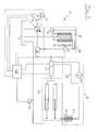
- Fig. 1 is a diagrammatic illustration of an exemplary disclosed cooling arrangement
- Fig. 2 is an exemplary flowchart for a method of temperature control corresponding to the cooling arrangement of Fig. 1.
- the brake temperature control arrangement 10 includes a pump 12, which may be any type of pump or it may be a plurality of pumps working together to provide fluid to various portions of the brake temperature control arrangement 10.
- the pump 12 may be a variable displacement pump driven by a power source 14 and a variable fluid output may be provided by adjusting a swash angle of the pump 12, by varying the speed of the power source 14 or by a combination of both.
- the pump 12 may draw a fluid such as, for example, an oil or more specifically a hydraulic oil, from a reservoir 16 and may pump the pressurised fluid to a first valve 18.
- This first valve 18 may be a system valve and may distribute fluid towards various machine systems such as steering and brake operation (both not shown), etc.
- a cooling portion generally designated as portion 30.
- the cooling portion 30 may include more or fewer components and is designated as such for clarity purposes only.
- the cooling portion 30 may include a motor 32 such as a fluid driven variable displacement motor wherein the rotational speed of the variable displacement motor may be dependent on the volume of fluid it receives, the swash angle of the motor or a combination of both.
- the motor 32 may also be of any other suitable kind or type, such as for example an electric motor.
- the motor 32 may drive a fan 34 for pulling or pushing air through or over at least one or more heat exchangers such as an intercooler 35, an engine coolant radiator 36 and a fluid cooler 38.
- the fan 34 is typically a variable speed fan.
- the fluid cooler 38 may be configured to cool the fluid provided by the pump 12 and used to drive the motor 32.
- the fluid may then be returned to the reservoir 16 such that the temperature of the bulk fluid may be influenced. It is to be understood that more or fewer heat exchangers may be used and that the type of heat exchanger may also be chosen as preferred.
- a by-pass arrangement 40 may be provided to allow fluid to by-pass the heat exchanger 38 to allow the fluid to warm up rapidly and to protect the heat exchanger from overpressurisation
- the power source 14 may be an internal combustion engine and may be provided with at least two sensors 20 and 22.
- An engine coolant used to control the temperature of the internal combustion engine may be directed to the engine coolant radiator 36 if cooling may be deemed necessary, and the sensor 20 may be used to monitor the temperature of the engine coolant (T2).
- the internal combustion engine may be a turbocharged and intercooled engine wherein the intake air may be firstly compressed by a turbocharger (not shown) and subsequently fed through the intercooler 35 to lower the temperature of the intake air.
- the sensor 22 may be a temperature sensor in the inlet manifold for sensing the temperature of the intake air (T3).
- the system valve 18 may also direct a portion of the fluid as displaced by the pump 12 to the control valve 24.
- the control valve 24 may be an on-demand control valve (ODCV) and may control the flow to both a brake arrangement 60 and a machine function portion 90. The flow to either of the brake arrangement 60 and the machine function portion 90 may be triggered by an operator or system command.
- the control valve 24 may also be a priority valve for prioritizing flow to the machine function portion 90 over the brake arrangement 60 or vice versa.
- the control valve 24 may also reduce the pressure of the fluid directed to the brake arrangement 60 as the pressure generated by the pump 12 may due to the various system demands be higher than the maximum operating pressure of the brake arrangement 60.
- the brake temperature control arrangement 10 may be applied to a dump truck.
- a dump truck Such a machine has a loading platform that may be raised to tip the load of the platform and the machine function portion 90 may be a hoisting arrangement for raising and lowering the platform. At least a portion of the control valve 24 may then be regarded as a hoist valve.
- the brake arrangement may be a brake arrangement as used with a drive axle of a machine (not shown). At least a portion of the brake arrangement may be sealed within the axle and may include a wet disc brake arrangement 92 having multiple brake discs at least partially immersed in a fluid bath 94. The fluid may be the same as the one stored in the reservoir 16.
- the brake arrangement 60 may further include a heat exchanger 96 which may use engine coolant to either cool or heat the fluid flowing from the control valve 24 to the fluid bath 94.
- a sensor 26 Downstream of the fluid bath 94 and the wet disc brake arrangement 92 there may be provided a sensor 26. Downstream in this context may also include a position at or near the brake arrangement 60.
- the sensor 26 may be a temperature sensor for sensing the temperature of the fluid leaving the fluid bath 94 and the wet disc brake arrangement 92.
- the sensor 26 is preferably arranged in such a manner that it senses the temperature of fluid leaving the fluid bath 94 and the wet disc brake arrangement 92 in a direct manner such that the temperature T1 corresponds closely to the temperature of the fluid bath 94 and the wet disc brake arrangement 92. Sensing just this temperature may contribute to increasing the chance of accurately determining the temperature of the fluid leaving these components and hence the temperature of the components themselves.
- the sensing feed line 98 allows a small continuous flow of fluid through the fluid bath 94 and the wet disc brake arrangement 92 to the sensor 26.
- an electronic control unit (ECU) 28 may be provided and configured to receive the signals from the sensors 20, 22 and 26.
- the ECU 28 may also be configured to control and alter the swash angles of the pump 14 and the motor 32.
- the ECU 28 may furthermore be configured to control the control valve 24 so as to alter the flow to the brake arrangement 60, prioritize the flow to the machine function portion 90 over the brake arrangement 60, or vice versa.
- the method and brake temperature control arrangement as disclosed may be useful for a wide range of applications and in particularly for industrial machines such as dump trucks, telehandlers and the like.
- a first step 110 may be to provide a flow of fluid using a suitable arrangement such as a pump 12. Via the system valve 18, the fluid may be distributed to the cooling arrangement 30, the control valve 24 and any other systems that may require fluid.
- a temperature downstream of the fluid bath 94 and the wet disc brake arrangement 92, hereinafter designated as T1 may be sensed by sensor 26 and a signal indicative of this temperature may be send to the ECU 28 for processing in step 113.
- a first temperature range (T a1 -T b1 ) may be determined for the brake arrangement 60, which may for example be a preferred range, an optimum range or an allowable range. This determination may include retrieving data previously stored in the ECU 28.
- the ECU 28 may determine if T1 falls within T a1 -T b1 or is outside the boundaries. If T1 falls within T a1 -T b1 no action may be taken as shown in step 126. If T1 is outside the boundaries of T a1 -T b1 an adjustment of a fluid parameter may be requested.
- the available range of fluid parameter adjustment may include increasing fan speed, decreasing fan speed, increasing flow rate, decreasing flow rate and any suitable combination thereof.
- T1 ⁇ T a1- T b1 i.e. the fluid temperature T1 sensed by the sensor 26 is below the first range
- several fluid parameter adjustments may be requested. Firstly a decrease in fan speed may be requested as shown in step 122. A decrease in fan speed may reduce the cooling effect of the cooling air on the heat exchangers 35, 36 and 38, hence the fluid may not be cooled or be cooled to a lesser degree and due to heat dissipation from the brake temperature control arrangement 10, the fluid may warm up.
- a decrease in flow rate through the fluid bath 94 and the wet disc brake arrangement 92 may be requested as shown in step 128.
- a reduction of fluid flow may allow the fluid bath 94 and the wet disc brake arrangement 92 to warm up which will then translate into a higher T1.
- an increase in flow rate through the fluid bath 94 and the wet disc brake arrangement 92 may be requested as shown in step 130. If for example the temperature of the fluid flowing towards the fluid bath 94 and the wet disc brake arrangement 92 is higher than the temperature of the fluid bath 94 and the wet disc brake arrangement 92, the fluid may actually warm up the fluid bath 94 and the wet disc brake arrangement 92. In this situation an increase in flow may warm up the fluid bath 94 and the wet disc brake arrangement 92 more rapidly.
- a combination of the above adjustments may be possible, for example, a decrease in fan speed and a decrease in flow rate may be requested simultaneously.
- T1>T a1- T b1 i.e. the temperature T1 measured by the sensor 26 is too high
- the following actions may be requested. Firstly, an increase in flow rate through the fluid bath 94 and the wet disc brake arrangement 92 may be requested as shown in step 130. Such increase in flow rate may increase the cooling effect and hence the temperature T1 sensed by the sensor 26 may drop over time.
- an increase in speed of the fan 34 may be requested as shown in step 124. An increase in speed of the fan 34 may increase the cooling of the fluid flowing through the fluid cooler 38. The fluid leaving the fluid cooler 38 may then reduce the temperature of the bulk fluid in the reservoir 16.
- both an increase in speed of the fan 34 and an increase in flow rate through the fluid bath 94 and the wet disc brake arrangement 92 may be requested simultaneously if preferred.
- the steps 314-326 regarding the engine coolant temperature (T3) and the steps 214-226 for the air intake temperature (T2) may be regarded as similar to the steps 114-126.
- Like numerals have like functions or considerations attached. It is to be understood however that the processes for T1, T2 and T3 need not be identical. Any suitable individual variation may be made as preferred.
- the steps 210 and 310 may be taken simultaneously or sequentially to the above steps and in the steps 210 and 310 the air intake temperature T2 (step 210) and the engine coolant temperature T3 (step 310) may be sensed.
- a second temperature range (T a2 -T b2 ) is determined for the air intake temperature T2, which may for example be a preferred range, an optimum range or an allowable range.
- the ECU 28 evaluates the air intake temperature T2 by determining if T2 falls within the range T a2 -T b2 . If T2 ⁇ T a2 -T b2 a fan speed decrease may be requested in step 222. If T2>T a2 -T b2 a fan speed increase may be requested in step 224. If T2 is in the range of T a2 -T b2 a fan speed no action may be requested in step 226.
- a third temperature range (T a3 -T b3 ) is determined for the engine coolant temperature T3, which may for example be a preferred range, an optimum range or an allowable range.
- the ECU 28 evaluates the engine coolant temperature T3 by determining if T3 falls within the range T a3 -T b3 . If T3 ⁇ T a3 -T b3 a fan speed decrease may be requested in step 322. If T3>T a3 -T b3 a fan speed increase may be requested in step 324. If T3 is in the range of T a3 -T b3 a fan speed no action may be requested in step 226.
- All requests for fluid parameter adjustment may be considered by the ECU 28 in step 132.
- the ECU 28 may in response make a number of fluid parameter adjustments including various combinations thereof to move any of T1, T2 and T3 to their respective first, second and third ranges. If all of the conditions T a1 ⁇ T1 ⁇ T b1, T a2 ⁇ T2 ⁇ T b2 and T a3 ⁇ T3 ⁇ T b3 are fulfilled no action may be taken as all three temperatures are within their respective first, second and third range. This cycle of the process may then end with step 132 wherein the ECU 28 decides upon comparing all requests that no adjustment of a fluid parameter may be required.
- T1, T2 and T3 result in conflicting requests, i.e. simultaneous requests for no action and one for an increase in flow.
- the ECU 28 may therefore evaluate all requests and weigh the importance of each or prioritise the various requests. If it is determined that one request may be critical, this request may be regarded as being an overriding request and may be the one that is executed. For example in a situation wherein T1 ⁇ T a1 -T b1 and T2>T a2 -T b2 the ECU 28 may receive requests for a decrease in fan speed via step 122, a request for a decrease in flow via step 128 and a request for an increase in fan speed via step 224.
- the ECU 28 may decide that decreasing T2 may be more critical than T1 and may adjust a fluid parameter via step 134 by increasing the fan speed. Of course the ECU 28 may still allow a decrease in flow in accordance with step 128.
- Any of the above processes may run cyclically and a repeated cycle may be started from any suitable starting point in the process.
- ECU 28 It is to be understood that a variety of decisions may be made by the ECU 28 and that the ECU 28 may be programmed differently depending on factors such as system design, machine type, individual component requirements, external factors, ambient operating conditions, etc.
Landscapes
- Engineering & Computer Science (AREA)
- General Engineering & Computer Science (AREA)
- Mechanical Engineering (AREA)
- Braking Arrangements (AREA)
- Valves And Accessory Devices For Braking Systems (AREA)
Abstract
Description
- The present disclosure is directed to an arrangement for controlling a temperature of a machine, and more particularly but not exclusively, to an arrangement for on demand machine brake cooling with a controllable cooling arrangement.
- Some types of machines, such as for example certain types of articulated dump trucks and telehandlers, have drive axles with integrated wet brake arrangements. In such arrangements the brake discs run in a bath filled with a fluid, such as an oil, to dissipate heat created during retarding of the machine and to prolong the general service life of the brake discs. The fluid may be sealed in the axle and replaced at certain service intervals, or alternatively an intermittent or continuous flow of fluid may take place through the axles.
- The latter is a method which is a subject of
European Patent Application EP1561963A1 , a disclosure aimed at preventing an excessive build up of pressure in a brake arrangement. By driving a set of pumps via a fixed flow pump and a splitter valve and controlling the flow through the brake arrangement based on pressure data collected from the brake arrangement, the system prevents overpressurisation of the brake arrangement. However, the system is complicated, utilizing a significant number of pumps, motors and valves, and the system does not address the problem of accurately controlling the temperature of the brakes. Furthermore, the system ofEP1561963A1 provides for a constant flow from the pump resulting in significant parasitic power loss and fuel consumption. - The current disclosure has the object of improving or overcoming at least some of these disadvantages.
- The disclosure provides a method of controlling the temperature of a brake arrangement (60) for a machine. A flow of pressurised fluid is provided to the brake arrangement (60) and a first temperature (T1) of the fluid downstream of the brake arrangement (60) is sensed. A first temperature range for the brake arrangement (60) is determined and it is determined if the first sensed temperature (T1) falls in the first temperature range. A request may be made to adjust at least one fluid parameter of the flow of pressurised fluid in response to determining that the first sensed temperature (T1) does not fall within the first temperature range such that the sensed temperature (T1) moves to the first temperature range.
The disclosure further provides a brake temperature control arrangement (10) for a machine having a brake arrangement (60), a source of pressurised fluid (12), a system valve (18) for distributing pressurised fluid from the fluid source (12) to the brake arrangement (60), and a first temperature sensor (26) configured to sense a first temperature (T1) indicative of a temperature of the brake arrangement (60). The arrangement further includes an electronic control unit (28) configured for receiving temperature data from the first temperature sensor (26) and to compare the temperature data with at least one stored value indicative of a first temperature range, the electronic control unit (28) further configured to adjust the temperature of the brake arrangement (60) by adjusting at least one parameter of the pressurised fluid if the sensed first temperature (T1) does not fall within the first temperature range. - Other features and aspects of this disclosure will be apparent from the following description and the accompanying drawings.
- Fig. 1 is a diagrammatic illustration of an exemplary disclosed cooling arrangement; and
- Fig. 2 is an exemplary flowchart for a method of temperature control corresponding to the cooling arrangement of Fig. 1.
- Now referring to Fig. 1, a brake temperature control arrangement generally designated as 10 is shown as an exemplary embodiment of the current disclosure. The brake
temperature control arrangement 10 includes apump 12, which may be any type of pump or it may be a plurality of pumps working together to provide fluid to various portions of the braketemperature control arrangement 10. In one embodiment, thepump 12 may be a variable displacement pump driven by apower source 14 and a variable fluid output may be provided by adjusting a swash angle of thepump 12, by varying the speed of thepower source 14 or by a combination of both. Thepump 12 may draw a fluid such as, for example, an oil or more specifically a hydraulic oil, from areservoir 16 and may pump the pressurised fluid to afirst valve 18. Thisfirst valve 18 may be a system valve and may distribute fluid towards various machine systems such as steering and brake operation (both not shown), etc. One such system that will be discussed in more detail is a cooling portion generally designated asportion 30. - It is to be understood that the
cooling portion 30 may include more or fewer components and is designated as such for clarity purposes only. Thecooling portion 30 may include amotor 32 such as a fluid driven variable displacement motor wherein the rotational speed of the variable displacement motor may be dependent on the volume of fluid it receives, the swash angle of the motor or a combination of both. Themotor 32 may also be of any other suitable kind or type, such as for example an electric motor. Themotor 32 may drive afan 34 for pulling or pushing air through or over at least one or more heat exchangers such as anintercooler 35, anengine coolant radiator 36 and a fluid cooler 38. Thefan 34 is typically a variable speed fan. The fluid cooler 38 may be configured to cool the fluid provided by thepump 12 and used to drive themotor 32. The fluid may then be returned to thereservoir 16 such that the temperature of the bulk fluid may be influenced. It is to be understood that more or fewer heat exchangers may be used and that the type of heat exchanger may also be chosen as preferred. A by-pass arrangement 40 may be provided to allow fluid to by-pass the heat exchanger 38 to allow the fluid to warm up rapidly and to protect the heat exchanger from overpressurisation - In one embodiment the
power source 14 may be an internal combustion engine and may be provided with at least twosensors engine coolant radiator 36 if cooling may be deemed necessary, and thesensor 20 may be used to monitor the temperature of the engine coolant (T2). The internal combustion engine may be a turbocharged and intercooled engine wherein the intake air may be firstly compressed by a turbocharger (not shown) and subsequently fed through theintercooler 35 to lower the temperature of the intake air. Thesensor 22 may be a temperature sensor in the inlet manifold for sensing the temperature of the intake air (T3). - The
system valve 18 may also direct a portion of the fluid as displaced by thepump 12 to thecontrol valve 24. Thecontrol valve 24 may be an on-demand control valve (ODCV) and may control the flow to both abrake arrangement 60 and a machine function portion 90. The flow to either of thebrake arrangement 60 and the machine function portion 90 may be triggered by an operator or system command. Thecontrol valve 24 may also be a priority valve for prioritizing flow to the machine function portion 90 over thebrake arrangement 60 or vice versa. Thecontrol valve 24 may also reduce the pressure of the fluid directed to thebrake arrangement 60 as the pressure generated by thepump 12 may due to the various system demands be higher than the maximum operating pressure of thebrake arrangement 60. - In one embodiment the brake
temperature control arrangement 10 may be applied to a dump truck. Such a machine has a loading platform that may be raised to tip the load of the platform and the machine function portion 90 may be a hoisting arrangement for raising and lowering the platform. At least a portion of thecontrol valve 24 may then be regarded as a hoist valve. - In one embodiment the brake arrangement may be a brake arrangement as used with a drive axle of a machine (not shown). At least a portion of the brake arrangement may be sealed within the axle and may include a wet
disc brake arrangement 92 having multiple brake discs at least partially immersed in afluid bath 94. The fluid may be the same as the one stored in thereservoir 16. Thebrake arrangement 60 may further include a heat exchanger 96 which may use engine coolant to either cool or heat the fluid flowing from thecontrol valve 24 to thefluid bath 94. - Downstream of the
fluid bath 94 and the wetdisc brake arrangement 92 there may be provided asensor 26. Downstream in this context may also include a position at or near thebrake arrangement 60. Thesensor 26 may be a temperature sensor for sensing the temperature of the fluid leaving thefluid bath 94 and the wetdisc brake arrangement 92. Thesensor 26 is preferably arranged in such a manner that it senses the temperature of fluid leaving thefluid bath 94 and the wetdisc brake arrangement 92 in a direct manner such that the temperature T1 corresponds closely to the temperature of thefluid bath 94 and the wetdisc brake arrangement 92. Sensing just this temperature may contribute to increasing the chance of accurately determining the temperature of the fluid leaving these components and hence the temperature of the components themselves. However, it may be preferred to combine the return flow from thefluid bath 94 and the wetdisc brake arrangement 92 with another return flow, but if the influence of external factors on the temperature of the return flow is kept to a minimum, a better temperature control of thefluid bath 94 and the wetdisc brake arrangement 92 may be possible. - To enable the
sensor 26 to sense the temperature of thefluid bath 94 and the wetdisc brake arrangement 92 continuously even when thecontrol valve 24 prevents a flow of fluid to thebrake arrangement 60, thesensing feed line 98 allows a small continuous flow of fluid through thefluid bath 94 and the wetdisc brake arrangement 92 to thesensor 26. - In one embodiment an electronic control unit (ECU) 28 may be provided and configured to receive the signals from the
sensors pump 14 and themotor 32. TheECU 28 may furthermore be configured to control thecontrol valve 24 so as to alter the flow to thebrake arrangement 60, prioritize the flow to the machine function portion 90 over thebrake arrangement 60, or vice versa. - The method and brake temperature control arrangement as disclosed may be useful for a wide range of applications and in particularly for industrial machines such as dump trucks, telehandlers and the like.
- Referring to Fig. 2, it is to be understood that the flowchart is to be interpreted for exemplary purposes only. The steps as shown may, for example, be performed in any suitable order, certain steps may be performed repeatedly, and steps may be delayed and skipped altogether if preferred.
- A
first step 110 may be to provide a flow of fluid using a suitable arrangement such as apump 12. Via thesystem valve 18, the fluid may be distributed to thecooling arrangement 30, thecontrol valve 24 and any other systems that may require fluid. Instep 112, a temperature downstream of thefluid bath 94 and the wetdisc brake arrangement 92, hereinafter designated as T1, may be sensed bysensor 26 and a signal indicative of this temperature may be send to theECU 28 for processing instep 113. At step 114 a first temperature range (Ta1-Tb1) may be determined for thebrake arrangement 60, which may for example be a preferred range, an optimum range or an allowable range. This determination may include retrieving data previously stored in theECU 28. At steps 116-120 theECU 28 may determine if T1 falls within Ta1-Tb1 or is outside the boundaries. If T1 falls within Ta1-Tb1 no action may be taken as shown in step 126. If T1 is outside the boundaries of Ta1-Tb1 an adjustment of a fluid parameter may be requested. - In one embodiment the available range of fluid parameter adjustment may include increasing fan speed, decreasing fan speed, increasing flow rate, decreasing flow rate and any suitable combination thereof.
- If the conditions Ta1<T1<Tb1 is fulfilled no action may be taken as the temperature is within the first range.
- If T1<Ta1-Tb1, i.e. the fluid temperature T1 sensed by the
sensor 26 is below the first range, several fluid parameter adjustments may be requested. Firstly a decrease in fan speed may be requested as shown instep 122. A decrease in fan speed may reduce the cooling effect of the cooling air on theheat exchangers temperature control arrangement 10, the fluid may warm up. Secondly, a decrease in flow rate through thefluid bath 94 and the wetdisc brake arrangement 92 may be requested as shown instep 128. If the fluid is having a cooling effect on thefluid bath 94 and the wetdisc brake arrangement 92, a reduction of fluid flow may allow thefluid bath 94 and the wetdisc brake arrangement 92 to warm up which will then translate into a higher T1. Thirdly, an increase in flow rate through thefluid bath 94 and the wetdisc brake arrangement 92 may be requested as shown instep 130. If for example the temperature of the fluid flowing towards thefluid bath 94 and the wetdisc brake arrangement 92 is higher than the temperature of thefluid bath 94 and the wetdisc brake arrangement 92, the fluid may actually warm up thefluid bath 94 and the wetdisc brake arrangement 92. In this situation an increase in flow may warm up thefluid bath 94 and the wetdisc brake arrangement 92 more rapidly. Fourthly, a combination of the above adjustments may be possible, for example, a decrease in fan speed and a decrease in flow rate may be requested simultaneously. - If T1>Ta1-Tb1, i.e. the temperature T1 measured by the
sensor 26 is too high, the following actions may be requested. Firstly, an increase in flow rate through thefluid bath 94 and the wetdisc brake arrangement 92 may be requested as shown instep 130. Such increase in flow rate may increase the cooling effect and hence the temperature T1 sensed by thesensor 26 may drop over time. Secondly, an increase in speed of thefan 34 may be requested as shown in step 124. An increase in speed of thefan 34 may increase the cooling of the fluid flowing through the fluid cooler 38. The fluid leaving the fluid cooler 38 may then reduce the temperature of the bulk fluid in thereservoir 16. This in turn may affect the cooling performance of the fluid when the fluid is pumped through thefluid bath 94 and the wetdisc brake arrangement 92. Again, both an increase in speed of thefan 34 and an increase in flow rate through thefluid bath 94 and the wetdisc brake arrangement 92 may be requested simultaneously if preferred. - The steps 314-326 regarding the engine coolant temperature (T3) and the steps 214-226 for the air intake temperature (T2) may be regarded as similar to the steps 114-126. Like numerals have like functions or considerations attached. It is to be understood however that the processes for T1, T2 and T3 need not be identical. Any suitable individual variation may be made as preferred. In one embodiment, the
steps steps ECU 28 for processing instep 113 and the subsequent processes may be conducted in a similar manner as described for T1 as shown in steps 214-226 and 314-326 in Fig. 2. Hence, atstep 214, a second temperature range (Ta2-Tb2) is determined for the air intake temperature T2, which may for example be a preferred range, an optimum range or an allowable range. At steps 216-220, theECU 28 evaluates the air intake temperature T2 by determining if T2 falls within the range Ta2-Tb2. If T2<Ta2-Tb2 a fan speed decrease may be requested instep 222. If T2>Ta2-Tb2 a fan speed increase may be requested in step 224. If T2 is in the range of Ta2-Tb2 a fan speed no action may be requested instep 226. - Similarly, at
step 314, a third temperature range (Ta3-Tb3) is determined for the engine coolant temperature T3, which may for example be a preferred range, an optimum range or an allowable range. At steps 316-320, theECU 28 evaluates the engine coolant temperature T3 by determining if T3 falls within the range Ta3-Tb3. If T3<Ta3-Tb3 a fan speed decrease may be requested instep 322. If T3>Ta3-Tb3 a fan speed increase may be requested instep 324. If T3 is in the range of Ta3-Tb3 a fan speed no action may be requested instep 226. - All requests for fluid parameter adjustment may be considered by the
ECU 28 instep 132. TheECU 28 may in response make a number of fluid parameter adjustments including various combinations thereof to move any of T1, T2 and T3 to their respective first, second and third ranges. If all of the conditions Ta1<T1<Tb1, Ta2<T2<Tb2 and Ta3<T3<Tb3 are fulfilled no action may be taken as all three temperatures are within their respective first, second and third range. This cycle of the process may then end withstep 132 wherein theECU 28 decides upon comparing all requests that no adjustment of a fluid parameter may be required. During operation it may be possible that the evaluations of T1, T2 and T3 result in conflicting requests, i.e. simultaneous requests for no action and one for an increase in flow. TheECU 28 may therefore evaluate all requests and weigh the importance of each or prioritise the various requests. If it is determined that one request may be critical, this request may be regarded as being an overriding request and may be the one that is executed. For example in a situation wherein T1<Ta1-Tb1 and T2>Ta2-Tb2 theECU 28 may receive requests for a decrease in fan speed viastep 122, a request for a decrease in flow viastep 128 and a request for an increase in fan speed via step 224. In such a conflicting set of requests theECU 28 may decide that decreasing T2 may be more critical than T1 and may adjust a fluid parameter viastep 134 by increasing the fan speed. Of course theECU 28 may still allow a decrease in flow in accordance withstep 128. - Any of the above processes may run cyclically and a repeated cycle may be started from any suitable starting point in the process.
- It is to be understood that a variety of decisions may be made by the
ECU 28 and that theECU 28 may be programmed differently depending on factors such as system design, machine type, individual component requirements, external factors, ambient operating conditions, etc. - Although the preferred embodiments of this invention have been described herein, improvements and modifications may be incorporated without departing from the scope of the following claims.
Claims (21)
- A method of controlling the temperature of a brake arrangement (60) for a machine comprising:providing a flow of pressurised fluid to the brake arrangement (60);sensing a first temperature (T1) of the fluid downstream of the brake arrangement (60);determining a first temperature range for the brake arrangement (60);determining if the first sensed temperature (T1) falls in the first temperature range;requesting an adjustment of at least one fluid parameter of said flow of pressurised fluid in response to determining that the first sensed temperature (T1) does not fall within the first temperature range such that the first sensed temperature (T1) moves to the first temperature range.
- A method according to claim 1, wherein requesting an adjustment of at least one fluid parameter includes requesting either an increase or a decrease in flow rate of the flow of pressurised fluid to the brake arrangement (60).
- A method according to any of the preceding claims, wherein the machine further has a cooling portion (30) including a variable speed cooling fan (34) configured for cooling a flow of pressurised fluid, wherein requesting an adjustment of at least one fluid parameter includes requesting adjustment of the temperature of the flow of pressurised fluid to the brake arrangement (60) by changing the speed of the cooling fan (34).
- A method according to any of the preceding claims, wherein the cooling portion (30) further includes a fluid cooler (38) and a by-pass arrangement (40) configured for allowing at least a portion of a flow of pressurised fluid to by-pass the fluid cooler (38), wherein requesting an adjustment of at least one fluid parameter includes requesting adjustment of the temperature of the flow of pressurised fluid to the brake arrangement (60) by at least partially opening or closing the by-pass arrangement (40).
- A method according to any of the preceding claims, wherein the cooling portion (30) is further configured to cool coolant of an engine (14) and the method further includes the steps of:sensing a second temperature (T2) corresponding to an engine coolant temperature;determining a second temperature range for the engine coolant;determining if the second sensed temperature (T2) falls in the second temperature range;requesting a change in speed of the variable speed cooling fan (34) in response to determining that the second sensed temperature (T2) does not fall within the second temperature range such that the second sensed temperature (T2) moves to the second temperature range.
- A method according to any of the preceding claims, wherein the cooling portion (30) is further configured to cool intake air of an engine (14) and the method further includes the steps of:sensing a third temperature (T3) corresponding to an engine intake air temperature;determining a third temperature range for the engine intake air;determining if the third sensed temperature (T3) falls in the third temperature range;requesting a change in speed of the variable speed cooling fan (34) in response to determining that the third sensed temperature (T3) does not fall within the third temperature range such that the third sensed temperature (T3) moves to the third temperature range.
- A method according to any of claims 5 to 6, further including the steps of:receiving at least one of: a) the request for an adjustment of at least one fluid parameter in response to determining that the sensed temperature (T1) does not fall within the first temperature range, b) the request for a change in speed of the variable speed cooling fan (34) in response to determining that the second sensed temperature (T2) does not fall within the second temperature range, and c) the request for a change in speed of the variable speed cooling fan (34) in response to determining that the third sensed temperature (T3) does not fall within the third temperature range; andperforming at least one adjustment or change corresponding to the at least one received request.
- A method according to any of claims 5 to 6, further including the steps of:receiving at least two of: a) the request for an adjustment of at least one fluid parameter in response to determining that the sensed temperature (T1) does not fall within the first temperature range, b) the request for a change in speed of the variable speed cooling fan (34) in response to determining that the second sensed temperature (T2) does not fall within the second temperature range, and c) the request for a change in speed of the variable speed cooling fan (34) in response to determining that the third sensed temperature (T3) does not fall within the third temperature range;determining if the at least two received requests correspond to conflicting adjustments or changes;prioritising the at least two requests in response to determining that the at least two requests correspond to conflicting adjustments or changes;performing an adjustment or change corresponding to at least one request that has received a higher priority.
- A method according to any of the preceding claims, wherein providing a flow of pressurised fluid to the brake arrangement (60) includes operating a variable displacement pump (12) for providing a variable flow of pressurised fluid to a control valve (24); and
controlling the control valve (24) to regulate the pressurised fluid flow to the brake arrangement (60). - A method according to claim 9, wherein the method further includes prioritising the flow of pressurised fluid via the control valve (24) such that either the brake arrangement (60) or another machine function (90) has a higher priority.
- A method according to any of the preceding claims, wherein at least a portion of the pressurised fluid flows continuously through the brake arrangement (60).
- A brake temperature control arrangement (10) for a machine comprising:a brake arrangement (60);a source of pressurised fluid (12);a system valve (18) for distributing pressurised fluid from the fluid source (12) to the brake arrangement (60);a first temperature sensor (26) configured to sense a first temperature (T1) indicative of a temperature of the brake arrangement (60);an electronic control unit (28) configured to receive temperature data from the first temperature sensor (26) and to compare the temperature data with at least one stored value indicative of a first temperature range, the electronic control unit (28) further configured to enable adjustment of the temperature of the brake arrangement (60) by adjusting at least one parameter of the pressurised fluid if the sensed first temperature (T1) does not fall within the first temperature range.
- A brake temperature control arrangement (10) according to claim 12 wherein the system valve (18) is controlled by the electronic control unit (28) and is configured to adjust a parameter of the pressurised fluid by adjusting the amount of pressurised fluid flowing the brake arrangement (60).
- A brake temperature control arrangement (10) according to any of claims 12 to 13, further including a cooling portion (30), wherein the cooling portion (30) includes a heat exchanger (38) with a variable speed cooling fan (34), the variable speed cooling fan (34) being controlled by the electronic control unit (28) and being configured to adjust a parameter of the fluid by adjusting the temperature of the pressurised fluid by adjusting the speed of the cooling fan.
- A brake temperature control arrangement (10) according to claim 14, wherein the cooling portion (30) further includes a second heat exchanger (36) for cooling engine coolant, and the arrangement further includes a second temperature sensor (20) configured to sense a second temperature (T2) indicative of the engine coolant;
the electronic control unit (28) further being configured for receiving temperature data from the second temperature sensor (20) and to compare the temperature data with at least one stored value indicative of a second temperature range, the electronic control unit (28) further configured to enable adjustment of the temperature engine coolant temperature (T2) by adjusting the speed of the cooling fan (34) if the second sensed temperature (T2) does not fall within the second temperature range. - A brake temperature control arrangement (10) according to any of claims 14 to 15, wherein the cooling portion (30) further includes a third heat exchanger (35) for cooling engine intake air, and the arrangement further includes a third temperature sensor (22) configured to sense a third temperature (T3) indicative of the engine intake air;
the electronic control unit (28) further being configured for receiving temperature data from the third temperature sensor (22) and to compare the temperature data with at least one stored value indicative of a third temperature range, the electronic control unit (28) further configured to enable adjustment of the engine air intake temperature (T3) by adjusting the speed of the cooling fan if the third sensed temperature (T3) does not fall within the third temperature range. - A brake temperature control arrangement (10) according to claim 16, wherein the electronic control unit (28) is configured to process the three temperature data (T1, T2, T3) and adjust at least one of the amount of pressurised fluid flowing the brake arrangement (60) and the speed of the cooling fan to move at least one of the first, second and third sensed temperatures (T1, T2, T3) to its respective first, second or third temperature range.
- A brake temperature control arrangement (10) according to any of claims 12 to 17, wherein the arrangement further includes a control valve (24) controlled by the electronic control unit (28), the control valve (24) being configured to divert at least a portion of the fluid that is flowing substantially towards the brake arrangement (60) away from the brake arrangement (60) if a machine function command is received by the electronic control unit (28).
- A brake temperature control arrangement (10) according to any of claims 12 to 18, further including a variable displacement pump (12) adapted for providing a variable flow of pressurised fluid to the brake temperature control arrangement (10).
- A brake temperature control arrangement (10) according to any of claims 12 to 19, wherein the temperature sensor (26) is configured for being located in a flow flowing substantially away from the brake arrangement (60).
- A machine comprising a brake temperature control arrangement (10) according to any of claims 12 to 10.
Priority Applications (2)
| Application Number | Priority Date | Filing Date | Title |
|---|---|---|---|
| EP06124773A EP1925844A1 (en) | 2006-11-24 | 2006-11-24 | Method and arrangement for machine cooling |
| US11/984,705 US8006813B2 (en) | 2006-11-24 | 2007-11-21 | Method and arrangement for machine cooling |
Applications Claiming Priority (1)
| Application Number | Priority Date | Filing Date | Title |
|---|---|---|---|
| EP06124773A EP1925844A1 (en) | 2006-11-24 | 2006-11-24 | Method and arrangement for machine cooling |
Publications (1)
| Publication Number | Publication Date |
|---|---|
| EP1925844A1 true EP1925844A1 (en) | 2008-05-28 |
Family
ID=37910895
Family Applications (1)
| Application Number | Title | Priority Date | Filing Date |
|---|---|---|---|
| EP06124773A Withdrawn EP1925844A1 (en) | 2006-11-24 | 2006-11-24 | Method and arrangement for machine cooling |
Country Status (2)
| Country | Link |
|---|---|
| US (1) | US8006813B2 (en) |
| EP (1) | EP1925844A1 (en) |
Cited By (1)
| Publication number | Priority date | Publication date | Assignee | Title |
|---|---|---|---|---|
| CN119532354A (en) * | 2023-08-31 | 2025-02-28 | 芜湖伯特利电子控制系统有限公司 | Control method and device for solving vehicle brake fluid overheating |
Families Citing this family (9)
| Publication number | Priority date | Publication date | Assignee | Title |
|---|---|---|---|---|
| US20080098998A1 (en) * | 2006-10-30 | 2008-05-01 | Dicke Paul A | Engine mounted air-to-air aftercooler |
| US20110005852A1 (en) | 2009-07-10 | 2011-01-13 | Sand Darrel R | Liquid cooled brake |
| US8663058B2 (en) | 2012-01-23 | 2014-03-04 | Caterpillar Inc. | Brake assembly having piloted park brake housing |
| US9169884B2 (en) | 2012-01-23 | 2015-10-27 | Caterpillar Inc. | Wet brake assembly |
| US8626410B2 (en) | 2012-01-23 | 2014-01-07 | Caterpillar Inc. | Powertrain system having lockable differential |
| US9574660B2 (en) | 2014-02-21 | 2017-02-21 | Federal Signal Corporation | Hydraulic fan drive system |
| US10330126B2 (en) * | 2016-12-16 | 2019-06-25 | Caterpillar Inc. | Fan control system with electro-hydraulic valve providing three fan motor operational positions |
| DE102017007409A1 (en) * | 2017-07-11 | 2019-01-17 | Wabco Gmbh | Hydraulic power brake system and method for ABS control |
| CN111734763A (en) * | 2020-07-01 | 2020-10-02 | 吉林大学青岛汽车研究院 | A Wet Multi-Disc Brake Circulation Cooling System |
Citations (3)
| Publication number | Priority date | Publication date | Assignee | Title |
|---|---|---|---|---|
| EP1350982A2 (en) * | 2002-04-03 | 2003-10-08 | Meritor Heavy Vehicle Technology LLC | System for controlling the temperature of a vehicle drive train component including coolant circulation |
| WO2005054026A1 (en) * | 2003-12-08 | 2005-06-16 | Volvo Construction Equipment Holding Sweden Ab | Brake protection device, brake arrangement and method for controlling a brake temperature |
| EP1561963A1 (en) * | 2004-02-09 | 2005-08-10 | Astra Veicoli Industriali S.p.A. | Method and circuit for controlling the flow rate of the hydraulic oil in the brake cooling system of a vehicle |
Family Cites Families (7)
| Publication number | Priority date | Publication date | Assignee | Title |
|---|---|---|---|---|
| US5050710A (en) | 1990-04-10 | 1991-09-24 | Caterpillar Inc. | Wet disc brake mechanism |
| FR2668440B1 (en) * | 1990-10-30 | 1992-12-24 | Alsthom Gec | BRAKING SYSTEM FOR RAIL VEHICLE. |
| JP2002340065A (en) | 2001-05-18 | 2002-11-27 | Komatsu Forklift Co Ltd | Cooling oil circuit of wet type multi-disc brake |
| JP2004224510A (en) | 2003-01-23 | 2004-08-12 | Hitachi Sumitomo Heavy Industries Construction Crane Co Ltd | Braking device of winch and crane |
| JP2004224509A (en) | 2003-01-23 | 2004-08-12 | Hitachi Sumitomo Heavy Industries Construction Crane Co Ltd | Braking device of winch, cooling method for braking device, and crane equipped with braking device |
| JP2005054941A (en) | 2003-08-06 | 2005-03-03 | Toyota Industries Corp | Cooling oil circuit |
| DE102004021067A1 (en) * | 2004-04-29 | 2005-11-17 | Linde Ag | Multi-disc brake or clutch |
-
2006
- 2006-11-24 EP EP06124773A patent/EP1925844A1/en not_active Withdrawn
-
2007
- 2007-11-21 US US11/984,705 patent/US8006813B2/en not_active Expired - Fee Related
Patent Citations (3)
| Publication number | Priority date | Publication date | Assignee | Title |
|---|---|---|---|---|
| EP1350982A2 (en) * | 2002-04-03 | 2003-10-08 | Meritor Heavy Vehicle Technology LLC | System for controlling the temperature of a vehicle drive train component including coolant circulation |
| WO2005054026A1 (en) * | 2003-12-08 | 2005-06-16 | Volvo Construction Equipment Holding Sweden Ab | Brake protection device, brake arrangement and method for controlling a brake temperature |
| EP1561963A1 (en) * | 2004-02-09 | 2005-08-10 | Astra Veicoli Industriali S.p.A. | Method and circuit for controlling the flow rate of the hydraulic oil in the brake cooling system of a vehicle |
Cited By (2)
| Publication number | Priority date | Publication date | Assignee | Title |
|---|---|---|---|---|
| CN119532354A (en) * | 2023-08-31 | 2025-02-28 | 芜湖伯特利电子控制系统有限公司 | Control method and device for solving vehicle brake fluid overheating |
| CN119532354B (en) * | 2023-08-31 | 2025-09-12 | 芜湖伯特利电子控制系统有限公司 | Control method and device for solving vehicle brake fluid overtemperature |
Also Published As
| Publication number | Publication date |
|---|---|
| US8006813B2 (en) | 2011-08-30 |
| US20080121476A1 (en) | 2008-05-29 |
Similar Documents
| Publication | Publication Date | Title |
|---|---|---|
| US8006813B2 (en) | Method and arrangement for machine cooling | |
| CN107499176B (en) | Method and device for cooling an electric drive system of a vehicle | |
| JP4489757B2 (en) | Control method of hydraulic system in operation engine of automobile | |
| US9726129B2 (en) | Method for determining a fuel fraction in oil | |
| JP5119481B2 (en) | Control device for fan for cooling vehicle | |
| EP3211194B1 (en) | Vehicle and method for controlling a variable speed water pump | |
| US10563564B2 (en) | Cooling fan and active grille shutter control | |
| US10816090B2 (en) | Oil supply system of an automatic transmission or automated manual transmission in a powertrain | |
| CN1798912B (en) | Propulsion system and method for optimising power supply to the cooling system thereof | |
| CN106523124B (en) | Method for operating oil circulation, especially for vehicles | |
| US6314727B1 (en) | Method and apparatus for controlling an electro-hydraulic fluid system | |
| EP1563146B1 (en) | A method for controlling a vehicle and a computer program for performing the method | |
| CN102383896A (en) | System for controlling hydraulic pressure and flow rate of oil in engine and control method thereof | |
| SE1050648A1 (en) | Method of SCR system and device of SCR system | |
| CN107002863A (en) | Hydraulic supply unit and control method | |
| US20180045100A1 (en) | Thermal management system and method for a vehicle | |
| CN110195638A (en) | Cooling system and internal combustion engine | |
| JP6029324B2 (en) | Construction machine that automatically adjusts fan rotation speed | |
| EP2935822B1 (en) | Cooling system in a vehicle | |
| WO2011005171A1 (en) | Device and method for improving performance of a motor vehicle | |
| JP2007518915A (en) | Method for operating the drive transmission system of an automobile | |
| US9523306B2 (en) | Engine cooling fan control strategy | |
| US6986554B2 (en) | Power dissipation management system | |
| JP2001527612A (en) | System to maintain engine oil at optimal temperature | |
| US12163459B2 (en) | Flow sharing control for multiple hydraulic fan motors |
Legal Events
| Date | Code | Title | Description |
|---|---|---|---|
| PUAI | Public reference made under article 153(3) epc to a published international application that has entered the european phase |
Free format text: ORIGINAL CODE: 0009012 |
|
| AK | Designated contracting states |
Kind code of ref document: A1 Designated state(s): AT BE BG CH CY CZ DE DK EE ES FI FR GB GR HU IE IS IT LI LT LU LV MC NL PL PT RO SE SI SK TR |
|
| AX | Request for extension of the european patent |
Extension state: AL BA HR MK RS |
|
| 17P | Request for examination filed |
Effective date: 20081028 |
|
| 17Q | First examination report despatched |
Effective date: 20081219 |
|
| AKX | Designation fees paid |
Designated state(s): AT BE BG CH CY CZ DE DK EE ES FI FR GB GR HU IE IS IT LI LT LU LV MC NL PL PT RO SE SI SK TR |
|
| STAA | Information on the status of an ep patent application or granted ep patent |
Free format text: STATUS: THE APPLICATION IS DEEMED TO BE WITHDRAWN |
|
| 18D | Application deemed to be withdrawn |
Effective date: 20090430 |