EP1925816A1 - Warming-up device of internal combustion engine - Google Patents
Warming-up device of internal combustion engine Download PDFInfo
- Publication number
- EP1925816A1 EP1925816A1 EP06782882A EP06782882A EP1925816A1 EP 1925816 A1 EP1925816 A1 EP 1925816A1 EP 06782882 A EP06782882 A EP 06782882A EP 06782882 A EP06782882 A EP 06782882A EP 1925816 A1 EP1925816 A1 EP 1925816A1
- Authority
- EP
- European Patent Office
- Prior art keywords
- heat storage
- storage material
- sliding member
- warming
- engine
- Prior art date
- Legal status (The legal status is an assumption and is not a legal conclusion. Google has not performed a legal analysis and makes no representation as to the accuracy of the status listed.)
- Withdrawn
Links
- 238000002485 combustion reaction Methods 0.000 title claims abstract description 51
- 238000005338 heat storage Methods 0.000 claims abstract description 89
- 239000011232 storage material Substances 0.000 claims abstract description 89
- 230000006911 nucleation Effects 0.000 claims abstract description 71
- 238000010899 nucleation Methods 0.000 claims abstract description 71
- 210000000078 claw Anatomy 0.000 claims abstract description 44
- 239000002826 coolant Substances 0.000 claims abstract description 25
- 229910052751 metal Inorganic materials 0.000 claims description 32
- 239000002184 metal Substances 0.000 claims description 32
- 230000008859 change Effects 0.000 claims description 17
- 239000000725 suspension Substances 0.000 claims description 11
- 239000012530 fluid Substances 0.000 claims description 5
- 239000000314 lubricant Substances 0.000 claims 1
- XLYOFNOQVPJJNP-UHFFFAOYSA-N water Substances O XLYOFNOQVPJJNP-UHFFFAOYSA-N 0.000 abstract description 45
- 238000007790 scraping Methods 0.000 description 23
- 239000000463 material Substances 0.000 description 16
- 239000012071 phase Substances 0.000 description 16
- 239000007790 solid phase Substances 0.000 description 8
- 230000004048 modification Effects 0.000 description 7
- 238000012986 modification Methods 0.000 description 7
- 230000008018 melting Effects 0.000 description 4
- 238000002844 melting Methods 0.000 description 4
- 230000007246 mechanism Effects 0.000 description 3
- 230000005855 radiation Effects 0.000 description 3
- 238000007789 sealing Methods 0.000 description 3
- AYRVGWHSXIMRAB-UHFFFAOYSA-M sodium acetate trihydrate Chemical compound O.O.O.[Na+].CC([O-])=O AYRVGWHSXIMRAB-UHFFFAOYSA-M 0.000 description 3
- 230000005540 biological transmission Effects 0.000 description 2
- 239000007791 liquid phase Substances 0.000 description 2
- 230000001154 acute effect Effects 0.000 description 1
- 230000008602 contraction Effects 0.000 description 1
- 230000003247 decreasing effect Effects 0.000 description 1
- 239000000203 mixture Substances 0.000 description 1
- 229920003002 synthetic resin Polymers 0.000 description 1
- 239000000057 synthetic resin Substances 0.000 description 1
- 238000010792 warming Methods 0.000 description 1
Images


Classifications
-
- F—MECHANICAL ENGINEERING; LIGHTING; HEATING; WEAPONS; BLASTING
- F01—MACHINES OR ENGINES IN GENERAL; ENGINE PLANTS IN GENERAL; STEAM ENGINES
- F01P—COOLING OF MACHINES OR ENGINES IN GENERAL; COOLING OF INTERNAL-COMBUSTION ENGINES
- F01P11/00—Component parts, details, or accessories not provided for in, or of interest apart from, groups F01P1/00 - F01P9/00
- F01P11/14—Indicating devices; Other safety devices
- F01P11/20—Indicating devices; Other safety devices concerning atmospheric freezing conditions, e.g. automatically draining or heating during frosty weather
-
- F—MECHANICAL ENGINEERING; LIGHTING; HEATING; WEAPONS; BLASTING
- F02—COMBUSTION ENGINES; HOT-GAS OR COMBUSTION-PRODUCT ENGINE PLANTS
- F02N—STARTING OF COMBUSTION ENGINES; STARTING AIDS FOR SUCH ENGINES, NOT OTHERWISE PROVIDED FOR
- F02N19/00—Starting aids for combustion engines, not otherwise provided for
- F02N19/02—Aiding engine start by thermal means, e.g. using lighted wicks
- F02N19/04—Aiding engine start by thermal means, e.g. using lighted wicks by heating of fluids used in engines
- F02N19/10—Aiding engine start by thermal means, e.g. using lighted wicks by heating of fluids used in engines by heating of engine coolants
-
- F—MECHANICAL ENGINEERING; LIGHTING; HEATING; WEAPONS; BLASTING
- F28—HEAT EXCHANGE IN GENERAL
- F28D—HEAT-EXCHANGE APPARATUS, NOT PROVIDED FOR IN ANOTHER SUBCLASS, IN WHICH THE HEAT-EXCHANGE MEDIA DO NOT COME INTO DIRECT CONTACT
- F28D20/00—Heat storage plants or apparatus in general; Regenerative heat-exchange apparatus not covered by groups F28D17/00 or F28D19/00
- F28D20/02—Heat storage plants or apparatus in general; Regenerative heat-exchange apparatus not covered by groups F28D17/00 or F28D19/00 using latent heat
- F28D20/028—Control arrangements therefor
-
- F—MECHANICAL ENGINEERING; LIGHTING; HEATING; WEAPONS; BLASTING
- F01—MACHINES OR ENGINES IN GENERAL; ENGINE PLANTS IN GENERAL; STEAM ENGINES
- F01P—COOLING OF MACHINES OR ENGINES IN GENERAL; COOLING OF INTERNAL-COMBUSTION ENGINES
- F01P11/00—Component parts, details, or accessories not provided for in, or of interest apart from, groups F01P1/00 - F01P9/00
- F01P11/14—Indicating devices; Other safety devices
- F01P2011/205—Indicating devices; Other safety devices using heat-accumulators
-
- F—MECHANICAL ENGINEERING; LIGHTING; HEATING; WEAPONS; BLASTING
- F01—MACHINES OR ENGINES IN GENERAL; ENGINE PLANTS IN GENERAL; STEAM ENGINES
- F01P—COOLING OF MACHINES OR ENGINES IN GENERAL; COOLING OF INTERNAL-COMBUSTION ENGINES
- F01P5/00—Pumping cooling-air or liquid coolants
- F01P5/10—Pumping liquid coolant; Arrangements of coolant pumps
- F01P5/12—Pump-driving arrangements
-
- F—MECHANICAL ENGINEERING; LIGHTING; HEATING; WEAPONS; BLASTING
- F02—COMBUSTION ENGINES; HOT-GAS OR COMBUSTION-PRODUCT ENGINE PLANTS
- F02D—CONTROLLING COMBUSTION ENGINES
- F02D41/00—Electrical control of supply of combustible mixture or its constituents
- F02D41/02—Circuit arrangements for generating control signals
- F02D41/04—Introducing corrections for particular operating conditions
- F02D41/06—Introducing corrections for particular operating conditions for engine starting or warming up
- F02D41/068—Introducing corrections for particular operating conditions for engine starting or warming up for warming-up
-
- Y—GENERAL TAGGING OF NEW TECHNOLOGICAL DEVELOPMENTS; GENERAL TAGGING OF CROSS-SECTIONAL TECHNOLOGIES SPANNING OVER SEVERAL SECTIONS OF THE IPC; TECHNICAL SUBJECTS COVERED BY FORMER USPC CROSS-REFERENCE ART COLLECTIONS [XRACs] AND DIGESTS
- Y02—TECHNOLOGIES OR APPLICATIONS FOR MITIGATION OR ADAPTATION AGAINST CLIMATE CHANGE
- Y02E—REDUCTION OF GREENHOUSE GAS [GHG] EMISSIONS, RELATED TO ENERGY GENERATION, TRANSMISSION OR DISTRIBUTION
- Y02E60/00—Enabling technologies; Technologies with a potential or indirect contribution to GHG emissions mitigation
- Y02E60/14—Thermal energy storage
Definitions
- the present invention relates to a warming-up device that warms up an internal combustion engine when the engine is started by rapidly increasing the temperature inside the engine.
- Patent Document 1 proposes a warming-up device which accommodates a latent heat storage material inside an internal combustion engine.
- the heat storage material stores heat generated by operating the internal combustion engine.
- the heat stored in the heat storage material is radiated when the engine is restarted after being stopped and accelerates the warming-up of the internal combustion engine.
- the warming-up device of Patent Document 1 is equipped with a nucleation device including a pair of electrodes inserted in the heat storage material.
- the nucleation device is operated by applying electric voltage to the electrodes from the outside. That is, the supercooled heat storage material is nucleated to generate phase change of the heat storage material so that heat is radiated from the heat storage material.
- a nucleation device disclosed in Patent Document 2 includes a disc spring arranged in a heat storage material and an external pressurizer, which is connected to the disc spring via an operation rod.
- the pressurizer reciprocates the operation rod, the disc spring is inverted, and the nucleation device starts operating. In this manner, the supercooled heat storage material is nucleate to generate phase change of the heat storage material so that heat is radiated from the heat storage material.
- Patent Document 1 Japanese Laid-Open Patent Publication No. 11-182393
- Patent Document 2 Japanese Laid-Open Patent Publication No. 6-257973
- a warming-up device of an internal combustion engine includes a latent heat storage material accommodated in the engine.
- the heat storage material is capable of becoming supercooled.
- a nucleation device is provided inside the heat storage material.
- the nucleation device includes a first sliding member and a second sliding member, which slide with respect to each other. The nucleation device operates to generate phase change of the heat storage material by nucleating the supercooled heat storage material from sliding portions between the sliding members.
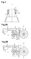
- Fig. 1 is a cross-sectional view of an internal combustion engine equipped with a warming-up device according to a first embodiment of the present invention as viewed from a crankshaft.
- the internal combustion engine 1 includes a cylinder block 11 in which a water jacket 13 is formed to surround cylinders 12.
- the water jacket 13 accommodates a container 14 filled with latent heat storage material X consisting of, for example, trihydrate sodium acetate (CH 3 COONA-3H 2 O).
- the container 14 is formed of a synthetic resin having a high thermal conductivity.
- the melting point of trihydrate sodium acetate is 58°C.
- the heat storage material X which is trihydrate sodium acetate in the first embodiment, has property in which although it is cooled from a temperature exceeding the melting point to a temperature less than or equal to the melting point, a phase change from a liquid phase to a solid phase does not occur, and is supercooled to -20°C to -30°C while storing latent heat.
- a nucleation device 2 which operates to generate the phase change of the heat storage material X, is located inside the container 14.
- the nucleation device 2 is operated by vibration generated at starting of the internal combustion engine 1 so that the phase change of the heat storage material X to the solid phase is generated to promptly release latent heat.
- the heat storage material X receives heat from the cylinder block 11. When the temperature exceeds the melting point, the phase of the heat storage material X is changed to the liquid phase and latent heat is stored.
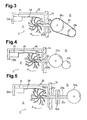
- the nucleation device 2 includes a support frame 20, a support piece 21, a shaft frame member 22, a rotating body 23, claws 24, a water wheel 25, and a plate-like member 29.
- the support frame 20 has a substantially channel-like cross-section.
- a first side piece 20a of the support frame 20 (right side piece in Fig. 2 ) is secured to the inner side surface of the container 14.
- the support piece 21 is fixed on a second side piece 20b of the support frame 20 (left side piece in Fig. 2 ).
- the shaft frame member 22 extends through substantially the center of the first side piece 20a of the support frame 20 in the vertical direction and corresponding part of the side wall of the container 14 so that the shaft frame member 22 is arranged in both the container 14 and the water jacket 13.
- a shaft 22a is rotatably supported in the shaft frame member 22, which is substantially cylindrical.
- the rotating body 23 is provided on the left end of the shaft frame member 22 located in the container 14. The rotating body 23 is coupled to the left end of the shaft 22a such that the rotating body 23 is rotatable about a rotation axis perpendicular to the shaft 22a.
- First sliding members which are the claws 24 in the first embodiment, are provided around the rotating body 23 at predetermined intervals.
- the claws 24 extend substantially radially from the rotating body 23.
- the water wheel 25 is provided on the right end of the shaft frame member 22 located in the water jacket 13.
- the water wheel 25 is coupled to the right end of the shaft 22a such that the water wheel 25 is rotatable about a rotation axis perpendicular to the shaft 22a.
- the water wheel 25 is rotated by coolant that circulates in the water jacket 13 as the internal combustion engine 1 is started.
- the rotational force of the water wheel 25 is transmitted to the rotating body 23 in the container 14 via the shaft 22a.
- the rotational force transmitted to the rotating body 23 rotates the claws 24 in a direction indicated by arrow A in Fig. 2A .
- a second sliding member which is the plate-like member 29 in the first embodiment, extends from the support piece 21 toward the first side piece 20a of the support frame 20 while being gently curved.
- the plate-like member 29 is formed of bimetal.
- the plate-like member 29 deforms to a sliding position (position shown in Fig. 2A ) at which the plate-like member 29 slides with respect to the claws 24 of the rotating body 23.
- the plate-like member deforms in a direction indicated by arrow B in Fig. 2B until it reaches a retracted position (position shown in Fig. 2B ) at which the plate-like member does not slide with respect to the claws 24 of the rotating body 23.
- the plate-like member 29 and the claws 24 of the rotating body 23 directly contact the heat storage material X, and when the heat storage material X is cooled to a temperature less than 40°C, for example, to a supercooled state, the plate-like member 29 is deformed to the sliding position shown in Fig. 2A .
- the rotational force of the water wheel 25 is transmitted to the rotating body 23 via the shaft 22a, thereby rotating the claws 24, which slide on the plate-like member 29 and scratch the surface of the plate-like member 29, thereby forming a new surface.
- the new surface is brought into direct contact with the supercooled heat storage material X, thereby nucleating the heat storage material X.
- the nucleation device 2 is operated. Based on the operation of the nucleation device 2, the phase change of the heat storage material X to the solid phase is generated, and latent heat is promptly released to the cylinder block 11.
- the water wheel 25 is oriented to be easily rotated by the coolant that circulates in the water jacket 13 as the internal combustion engine 1 is started.
- the first embodiment has the following advantages.
- the water wheel 25 is rotated by the coolant that circulates in the water jacket 13 as the internal combustion engine 1 is started, and the rotational force is transmitted to the rotating body 23 via the shaft 22a to rotate the claws 24.
- the mechanism for rotating the rotating body 23 is not limited to this.
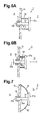
- a driven pulley 26a is provided on the right end of the shaft frame member 22 located in the water jacket 13, and the driven pulley 26a is coupled to the right end of the shaft 22a to be rotatable about a rotation axis perpendicular to the shaft 22a.
- a drive pulley 26b which is rotated by rotation of the crankshaft, is arranged in the water jacket 13 in the vicinity of the driven pulley 26a.
- the rotational force of the drive pulley 26b is transmitted to the driven pulley 26a by a belt 26c, which extends between the drive pulley 26b and the driven pulley 26a.
- the claws 24 may be rotated by transmitting the rotational force transmitted to the driven pulley 26a to the rotating body 23 via the shaft 22a.
- a driven gear 27a is provided on the right end of the shaft frame member 22 located in the water jacket 13, and the driven gear 27a is coupled to the right end of the shaft 22a in the shaft frame member 22 to be rotatable about a rotation axis perpendicular to the shaft 22a.
- a drive gear 27b which is rotated by the crankshaft, is arranged in the water jacket 13 in the vicinity of the driven gear 27a. The drive gear 27b engages with the driven gear 27a. The rotational force of the drive gear 27b is transmitted to the driven gear 27a, and the rotational force transmitted to the driven gear 27a is transmitted to the rotating body 23 via the shaft 22a.
- the claws 24 may be rotated in this manner.
- a rotating body 28a which is rotated by rotation of the crankshaft, is arranged in the water jacket 13 where the right end of the shaft frame member 22 is located.
- the shaft frame member 22 is divided into a first section 22b and a second section 22c.
- An electromagnetic clutch 28b which selectively disconnects and connects transmission of the rotational force via the shaft 22a, may be provided between the first section 22b and the second section 22c.
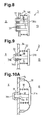
- a second embodiment of the present invention will be described with reference to Figs. 6A and 6B .
- the structure of the nucleation device is modified. Since the structure other than the nucleation device is the same as that in the first embodiment, like members are given like numbers and detailed explanations are omitted.
- a nucleation device 3 includes a shaft member 31, a disc-like plate material 31a, a stopper 31b, an urging spring 32, and a rubber scraping member 33.
- a first sliding member which is the shaft member 31 in the second embodiment, extends through a through hole 14a formed in the side wall of the container 14.
- the disc-like plate material 31a is integrally attached to the right end of the shaft member 31.
- the urging spring 32 is mounted in the water jacket 13 between the disc-like plate material 31a and the side wall of the container 14 in a compressed state.
- An elastic body which is the urging spring 32 in the second embodiment, urges the shaft member 31 in a direction opposite to the container 14 (right side in Fig. 6 ).
- the stopper 31b is attached to the left end of the shaft member 31. The stopper 31b restricts the shaft member 31, which is urged by the urging spring 32, from moving by a predetermined amount or more in the direction opposite to the container 14.
- the annular rubber scraping member 33 is attached to the rim of the through hole 14a of the container 14.
- a second sliding member which is the rubber scraping member 33 in the second embodiment, closely contacts the shaft member 31, and scrapes the surface of the shaft member 31 when the shaft member 31 slides in the axial direction.
- the shaft member 31 When the internal combustion engine 1 is stopped, the shaft member 31 is urged in a direction opposite to the container 14 by the urging spring 32, but is restricted from moving by the predetermined amount or more by the stopper 31b. Part of the shaft member 31 protruding outside from the side wall of the container 14 contacts the coolant in the water jacket 13.
- the operation of the nucleation device 3 generates the phase change of the heat storage material X to the solid phase, and latent heat is promptly released to the cylinder block 11.
- the disc-like plate material 31a is oriented so that the pressure of the coolant generated in the water jacket 13 at the starting of the internal combustion engine 1 easily acts on the disc-like plate material 31a.
- the second embodiment has the following advantages.
- the urging spring 32 for urging the shaft member 31 in the direction opposite to the container 14 is a coil spring, but this may be changed.
- elastic bodies which are a pair of leaf spring members 35, are arranged in the water jacket 13 between the disc-like plate material 31a and the side wall of the container 14.
- the leaf spring members 35 are arranged about the axis of the shaft member 31 at intervals of 180 degrees.
- the leaf spring members 35 may urge the shaft member 31 in a direction opposite to the container 14 (right side in Fig. 7 ).
- the single shaft member 31 slides with respect to the rubber scraping member 33 to be scraped.
- a number of (three in Fig. 8 ) shaft members 36 may be provided integrally with a disc-like plate material 36a having an enlarged diameter.
- Annular rubber scraping members 37 may be mounted on rims of through holes 14a of the container 14.
- Each of the rubber scraping members 37 which serves as the second sliding member, closely contacts corresponding one of the shaft members 36 separately, and scrapes the surface of the corresponding shaft member 36. In this case, by the pressure of the coolant generated at the starting of the internal combustion engine 1, each shaft member 36 is separately scraped. This is very advantageous in reliably nucleating the heat storage material X.
- annular sealing member 38 may be provided at the through hole 14a formed in the side wall of the container 14 on the side of the container 14 facing the water jacket 13.
- the sealing member 38 may seal the shaft member 31 in the water jacket 13. In this case, the sealing performance in the water jacket 13 is improved, thus effectively preventing the coolant from entering the container 14.
- part of the shaft member 31 protruding outside from the side wall of the container 14 when the internal combustion engine 1 is stopped is in contact with the coolant in the water jacket 13.
- a boot 39 may surround a space between the outer edge of the disc-like plate material 31a and the side wall of the container 14. That is, part of the shaft member 31 protruding outside from the side wall of the container 14 may be designed not to contact the coolant in the water jacket 13 both in the state before the pressure of the coolant acts on the disc-like plate material 31a (state shown in Fig. 10A ) and the state where the pressure of the coolant acts on the disc-like plate material 31a (state shown in Fig. 10B ). In this case, the coolant is further effectively prevented from entering the container 14.
- a third embodiment of the present invention will now be described with reference to Figs. 11A and 11B .
- the structure of the nucleation device is modified. Since the structure other than the nucleation device is the same as that in the first embodiment, like members are given like numbers and detailed explanations are omitted.
- a nucleation device 4 includes a shaft member 41, a first stopper member 42a, a second stopper member 42b, a collar member 43, a first urging spring 44a, a second urging spring 44b, and a pair of metal scraping members 45.
- a first sliding member, which is the shaft member 41 in the third embodiment, is arranged in the container 14.
- a rod-like member, which is the shaft member 41 in the third embodiment, is a cylindrical metal.
- the stopper members 42a, 42b are attached to the ends of the shaft member 41.
- the cylindrical collar member 43 is supported between the stopper members 42a, 42b to be movable in a direction of the axis m of the shaft member 41.
- the collar member 43 is arranged on the outer circumferential surface of the shaft member 41 with a gap provided in between.
- the urging springs 44a, 44b urge the collar member 43 to be balanced on the shaft member 41.
- the balanced collar member 43 is located substantially at the center between the stopper members 42a, 42b.
- the pair of annular metal scraping members 45 are attached to the first end (left end in Fig. 11 ) and the second end (right end in Fig. 11 ) of an inner circumferential surface 43a of the collar member 43, respectively.
- the annular metal scraping members 45 are located in the gap between the collar member 43 and the shaft member 41.
- the inner circumferential surface 43a of the collar member 43 is parallel to the direction of the axis m, which is a swinging direction of the collar member 43 serving as a weight.
- the first urging spring 44a (on left side in Fig. 11 ) is mounted between the first stopper member 42a (left side in Fig. 11 ) and the first end surface (left end surface in Fig. 11 ) of the collar member 43 in a compressed state.
- the second urging spring 44b (on right side in Fig. 11 ) is mounted between the second stopper member 42b (on right side in Fig. 11 ) and the second end surface (on right end surface in Fig. 11 ) of the collar member 43 in a compressed state.
- the nucleation device 4 operates to nucleate the heat storage material X by bringing the new surface into direct contact with the supercooled heat storage material X.
- the operation of the nucleation device 4 generates the phase change of the heat storage material X to the solid phase so that latent heat is promptly released to the cylinder block 11.
- the nucleation device 4 is arranged such that the axis m of the shaft member 41 extends substantially vertically so that the collar member 43 easily moves in the direction of the axis m of the shaft member 41 when the balanced state of the collar member 43 is cancelled.
- the third embodiment has the following advantages.
- a fourth embodiment of the present invention will now be described with reference to Fig. 12 .
- the structure of the nucleation device is modified. Since the structure other than the nucleation device is the same as that in the first embodiment, like members are given like numbers and detailed explanations are omitted.
- a nucleation device 5 includes a metal member 50, a weight 51, a coil spring 52, and a claw 53.
- the metal member 50 has a substantially channel-like cross-section, and is secured to the inner bottom surface of the container 14.
- the proximal end of the coil spring 52 (left end in Fig. 12 ) is attached to a first vertical wall 50a (left side vertical wall in Fig. 12 ) of the metal member 50.
- the substantially cubic weight 51 is attached to the distal end of a suspension member, which is the coil spring 52 in the fourth embodiment.
- the weight 51 swings vertically in Fig. 12 using the proximal end of the coil spring 52 as a fulcrum.
- the weight 51 has a right side surface 51a, which is substantially parallel to the swinging direction of the weight 51 (vertical direction in Fig. 12 ).
- a first sliding member which is the substantially conical claw 53 in the fourth embodiment, projects from the right side surface 51a of the weight 51.
- a second vertical wall 50b (right side vertical wall in Fig. 12 ) of the metal member 50 is a metal plate.
- the second vertical wall 50b functions as a second sliding member, which contacts the distal end of the claw 53 when the weight 51 is in the balanced state as shown in Fig. 12 .
- the coil spring 52 swings the weight 51 vertically using its proximal end attached to the first vertical wall 50a of the metal member 50 as a fulcrum. Then, the distal end of the claw 53 slides along the second vertical wall 50b of the metal member 50, thereby forming a new surface.
- the nucleation device 5 is operated by exposing the new surface to the heat storage material X, which generates the phase change of the heat storage material X to the solid phase so that latent heat is promptly released to the cylinder block 11.
- the coil spring 52 ends the vertical swing of the weight 51, and keeps the weight 51 in the balanced state.
- the fourth embodiment has the following advantages.
- a fifth embodiment of the present invention will now be described with reference to Fig. 13 .
- the structure of the nucleation device is modified. Since the structure other than the nucleation device is the same as that in the first embodiment, like members are given like numbers and detailed explanations are omitted.
- a nucleation device 6 includes a first support member 60, a second support member 61, a metal plate 62, a weight 63, coil springs 64, 65, and a claw 66.
- the substantially flat plate-like first support member 60 is secured to the inner bottom surface of the container 14.
- the substantially flat plate-like second support member 61 is secured to the upper surface in the container 14 so as to face the first support member 60 above the first support member 60.
- a second sliding member which is the substantially flat plate-like metal plate 62 in the fifth embodiment, includes a lower end attached to the first support member 60, and an upper end attached to the second support member 61.
- Suspension members which are the pair of upper and lower coil springs 64, 65 in the fifth embodiment, suspend the substantially cubic weight 63 to be vertically swingable between the first and second support members 60, 61.
- the weight 63 has a right side surface 63a, which is substantially parallel to a swinging direction of the weight 63.
- the substantially conical claw 66 projects from the right side surface 63a toward the metal plate 62.
- the coil springs 64, 65 expand and contract to swing the weight 63 in the vertical direction from the balanced state by the vibration generated at the starting of the internal combustion engine 1. Then, the distal end of the claw 66, which contacts the metal plate 62, slides along the surface of the metal plate 62, thereby exposing a new surface to the heat storage material X. In this manner, the nucleation device 6 operates to generate the phase change of the heat storage material X to the solid phase so that latent heat is promptly released to the cylinder block 11.
- the coil springs 64, 65 end the vertical swinging of the weight 63 when the vibration generated at the starting of the internal combustion engine 1 is stopped, and keep the weight 63 in the balanced state (state shown in Fig. 13 ).
- the fifth embodiment has the following advantages.
- the container 14 is arranged in the water jacket 13.
- a dedicated accommodating chamber may be formed in the cylinder block 11, and the container 14 may be arranged in the accommodating chamber.
- the suspension member is configured by the coil springs 52, 64, 65.
- the suspension member may be configured by linear members such as leaf springs assembled like a pantograph.
- the suspension member may be anything as long as the weight is vertically swung by the vibration generated at the starting of the internal combustion engine. In other words, the suspension member may be anything as long as an impact is applied to the supercooled heat storage material to generate the phase change when adjacent linear members contact or separate from each other.
Landscapes
- Engineering & Computer Science (AREA)
- Mechanical Engineering (AREA)
- General Engineering & Computer Science (AREA)
- Chemical & Material Sciences (AREA)
- Combustion & Propulsion (AREA)
- Life Sciences & Earth Sciences (AREA)
- Atmospheric Sciences (AREA)
- Physics & Mathematics (AREA)
- Thermal Sciences (AREA)
- Cylinder Crankcases Of Internal Combustion Engines (AREA)
Abstract
Description
- The present invention relates to a warming-up device that warms up an internal combustion engine when the engine is started by rapidly increasing the temperature inside the engine.
- In general, when starting an internal combustion engine, if the internal temperature of the engine, in particular, the temperature of the cylinder wall and the temperature of the combustion chamber are low, friction loss relative to the movement of the piston is increased, and the composition of exhaust gas is deteriorated.
- Thus, for example,
Patent Document 1 proposes a warming-up device which accommodates a latent heat storage material inside an internal combustion engine. The heat storage material stores heat generated by operating the internal combustion engine. The heat stored in the heat storage material is radiated when the engine is restarted after being stopped and accelerates the warming-up of the internal combustion engine. - The warming-up device of
Patent Document 1 is equipped with a nucleation device including a pair of electrodes inserted in the heat storage material. The nucleation device is operated by applying electric voltage to the electrodes from the outside. That is, the supercooled heat storage material is nucleated to generate phase change of the heat storage material so that heat is radiated from the heat storage material. - A nucleation device disclosed in
Patent Document 2 includes a disc spring arranged in a heat storage material and an external pressurizer, which is connected to the disc spring via an operation rod. When the pressurizer reciprocates the operation rod, the disc spring is inverted, and the nucleation device starts operating. In this manner, the supercooled heat storage material is nucleate to generate phase change of the heat storage material so that heat is radiated from the heat storage material. - However, in the conventional nucleation devices, the heat storage material is nucleate by applying electric voltage to the electrodes or inverting the disc spring by reciprocating the operation rod. Thus, the structure of the nucleation devices is very complicated, and the costs are increased.
Patent Document 1: Japanese Laid-Open Patent Publication No.11-182393
Patent Document 2: Japanese Laid-Open Patent Publication No.6-257973 - Accordingly, it is an objective of the present invention to provide an inexpensive warming-up device of an internal combustion engine that has a simple structure.
- In accordance with one aspect of the present invention, a warming-up device of an internal combustion engine is provided. The warming-up device includes a latent heat storage material accommodated in the engine. The heat storage material is capable of becoming supercooled. A nucleation device is provided inside the heat storage material. The nucleation device includes a first sliding member and a second sliding member, which slide with respect to each other. The nucleation device operates to generate phase change of the heat storage material by nucleating the supercooled heat storage material from sliding portions between the sliding members.
-
-
Fig. 1 is a cross-sectional view illustrating an internal combustion engine equipped with a warming-up device according to a first embodiment of the present invention as viewed in a direction of the crankshaft; -
Fig. 2A is a cross-sectional view illustrating a state where a plate-like member accommodated in the water jacket ofFig. 1 is deformed to a sliding position where the plate-like member slides with respect to claws of a rotating body; -
Fig. 2B is a cross-sectional view illustrating a state where the plate-like member inFig. 2A is deformed to a retracted position where the plate-like member inFig. 2A retracts from the claws of the rotating body; -
Fig. 3 is a cross-sectional view illustrating a nucleation device according to a modification of the first embodiment; -
Fig. 4 is a cross-sectional view illustrating a nucleation device according to another modification of the first embodiment; -
Fig. 5 is a cross-sectional view illustrating a nucleation device according to another modification of the first embodiment; -
Fig. 6A is a cross-sectional view illustrating a nucleation device of a warming-up device according to a second embodiment of the present invention, and a state before the pressure of the coolant acts on the disc-like plate material; -
Fig. 6B is a cross-sectional view illustrating a state where the pressure of the coolant acts on the disc-like plate material ofFig. 6A ; -
Fig. 7 is a cross-sectional view illustrating a nucleation device according to a modification of the second embodiment; -
Fig. 8 is a cross-sectional view illustrating a nucleation device according to another modification of the second embodiment; -
Fig. 9 is a cross-sectional view illustrating a nucleation device according to another modification of the second embodiment; -
Fig. 10A is a cross-sectional view illustrating a state before the pressure of the coolant acts on the disc-like plate material of a nucleation device according to another modification of the second embodiment; -
Fig. 10B is a cross-sectional view illustrating a state where the pressure of the coolant acts on the disc-like plate material ofFig. 10A ; -
Fig. 11A is a cross-sectional view illustrating a nucleation device of a warming-up device according to a third embodiment of the present invention, and a balanced state of a collar member achieved by urging springs; -
Fig. 11B is a cross-sectional view illustrating a state where the balanced state inFig. 11A is cancelled; -
Fig. 12 is a side view illustrating a nucleation device of a warming-up device according to a fourth embodiment of the present invention; and -
Fig. 13 is a side view illustrating a nucleation device of a warming-up device according to a fifth embodiment of the present invention. - The best mode for carrying out the invention will now be described in detail with reference to drawings.
-
Fig. 1 is a cross-sectional view of an internal combustion engine equipped with a warming-up device according to a first embodiment of the present invention as viewed from a crankshaft. Theinternal combustion engine 1 includes acylinder block 11 in which awater jacket 13 is formed to surroundcylinders 12. Thewater jacket 13 accommodates acontainer 14 filled with latent heat storage material X consisting of, for example, trihydrate sodium acetate (CH3COONA-3H2O). Thecontainer 14 is formed of a synthetic resin having a high thermal conductivity. The melting point of trihydrate sodium acetate is 58°C. The heat storage material X, which is trihydrate sodium acetate in the first embodiment, has property in which although it is cooled from a temperature exceeding the melting point to a temperature less than or equal to the melting point, a phase change from a liquid phase to a solid phase does not occur, and is supercooled to -20°C to -30°C while storing latent heat. - As shown in
Figs. 2A and 2B , anucleation device 2, which operates to generate the phase change of the heat storage material X, is located inside thecontainer 14. In a case where the temperature of theinternal combustion engine 1 is decreased and the heat storage material X is supercooled, thenucleation device 2 is operated by vibration generated at starting of theinternal combustion engine 1 so that the phase change of the heat storage material X to the solid phase is generated to promptly release latent heat. Furthermore, after releasing latent heat by the phase change to the solid phase, the heat storage material X receives heat from thecylinder block 11. When the temperature exceeds the melting point, the phase of the heat storage material X is changed to the liquid phase and latent heat is stored. - The
nucleation device 2 includes asupport frame 20, asupport piece 21, ashaft frame member 22, a rotatingbody 23,claws 24, awater wheel 25, and a plate-like member 29. Thesupport frame 20 has a substantially channel-like cross-section. A first side piece 20a of the support frame 20 (right side piece inFig. 2 ) is secured to the inner side surface of thecontainer 14. Thesupport piece 21 is fixed on asecond side piece 20b of the support frame 20 (left side piece inFig. 2 ). - The
shaft frame member 22 extends through substantially the center of the first side piece 20a of thesupport frame 20 in the vertical direction and corresponding part of the side wall of thecontainer 14 so that theshaft frame member 22 is arranged in both thecontainer 14 and thewater jacket 13. Ashaft 22a is rotatably supported in theshaft frame member 22, which is substantially cylindrical. The rotatingbody 23 is provided on the left end of theshaft frame member 22 located in thecontainer 14. The rotatingbody 23 is coupled to the left end of theshaft 22a such that the rotatingbody 23 is rotatable about a rotation axis perpendicular to theshaft 22a. - First sliding members, which are the
claws 24 in the first embodiment, are provided around the rotatingbody 23 at predetermined intervals. Theclaws 24 extend substantially radially from the rotatingbody 23. Thewater wheel 25 is provided on the right end of theshaft frame member 22 located in thewater jacket 13. Thewater wheel 25 is coupled to the right end of theshaft 22a such that thewater wheel 25 is rotatable about a rotation axis perpendicular to theshaft 22a. - The
water wheel 25 is rotated by coolant that circulates in thewater jacket 13 as theinternal combustion engine 1 is started. The rotational force of thewater wheel 25 is transmitted to therotating body 23 in thecontainer 14 via theshaft 22a. The rotational force transmitted to therotating body 23 rotates theclaws 24 in a direction indicated by arrow A inFig. 2A . - A second sliding member, which is the plate-
like member 29 in the first embodiment, extends from thesupport piece 21 toward the first side piece 20a of thesupport frame 20 while being gently curved. The plate-like member 29 is formed of bimetal. When the temperature of the heat storage material X in thecontainer 14 is less than 40°C, the plate-like member 29 deforms to a sliding position (position shown inFig. 2A ) at which the plate-like member 29 slides with respect to theclaws 24 of therotating body 23. When the temperature of the heat storage material X is 40°C or more, the plate-like member deforms in a direction indicated by arrow B inFig. 2B until it reaches a retracted position (position shown inFig. 2B ) at which the plate-like member does not slide with respect to theclaws 24 of therotating body 23. - The plate-
like member 29 and theclaws 24 of therotating body 23 directly contact the heat storage material X, and when the heat storage material X is cooled to a temperature less than 40°C, for example, to a supercooled state, the plate-like member 29 is deformed to the sliding position shown inFig. 2A . Thus, when thewater wheel 25 is rotated by the coolant that circulates in thewater jacket 13 as theinternal combustion engine 1 is started, the rotational force of thewater wheel 25 is transmitted to therotating body 23 via theshaft 22a, thereby rotating theclaws 24, which slide on the plate-like member 29 and scratch the surface of the plate-like member 29, thereby forming a new surface. The new surface is brought into direct contact with the supercooled heat storage material X, thereby nucleating the heat storage material X. In this manner, thenucleation device 2 is operated. Based on the operation of thenucleation device 2, the phase change of the heat storage material X to the solid phase is generated, and latent heat is promptly released to thecylinder block 11. In this case, thewater wheel 25 is oriented to be easily rotated by the coolant that circulates in thewater jacket 13 as theinternal combustion engine 1 is started. - The first embodiment has the following advantages.
- (1) The
nucleation device 2 operates to nucleate the heat storage material X from the sliding portions between the plate-like member 29 and theclaws 24 of therotating body 23 in the heat storage material X. Thus, for example, compared to cases where the heat storage material is nucleate by applying electric voltage to the electrodes or inverting the disc spring by reciprocation of the operation rod, the structure of thenucleation device 2 is much simplified and costs are reduced. - (2) The
water wheel 25 is rotated by the coolant that circulates in thewater jacket 13 as theinternal combustion engine 1 is started. The rotational force of thewater wheel 25 is transmitted to therotating body 23 via theshaft 22a, and as a result, theclaws 24 of therotating body 23 on the plate-like member 29. Theclaws 24 scratch the plate-like member 29 to form a new surface on the surface of the plate-like member 29. The new surface directly contacts the supercooled heat storage material X. This causes thenucleation device 2 to operate so as to nucleate the heat storage material X. Thus, heat is radiated from the heat storage material X when theinternal combustion engine 1 is started, and theinternal combustion engine 1 is smoothly warmed up. Furthermore, since the rotatingbody 23 is driven based on the pressure of fluid, that is, the pressure of the coolant generated when theinternal combustion engine 1 is started, the plate-like member 29 is reliably scratched by theclaws 24 with a stable force to form a new surface. - (3) The
claws 24 of therotating body 23, which is rotated as theinternal combustion engine 1 is started, slide with respect to and scratch the plate-like member 29 located on the rotational path of theclaws 24. This forms a new surface, thereby reliably nucleating the heat storage material X. Such a mechanism is very advantageous in warming up theinternal combustion engine 1 by the heat radiation from the heat storage material X. - (4) When the temperature of the heat storage material X in the
container 14 is less than 40°C, the plate-like member 29, which is formed of bimetal, moves to the sliding position (position shown inFig. 2A ) at which the plate-like member 29 slides with respect to theclaws 24 of therotating body 23, and when the temperature of the heat storage material X becomes greater than or equal to 40°C, the plate-like member 29 moves toward the direction indicated by arrow B inFig. 2B until it reaches the retracted position (position shown inFig. 2B ) at which the plate-like member 29 does not slide on theclaws 24 of therotating body 23. Thus, when the plate-like member 29 does not need to slide with respect to theclaws 24, that is, when the heat storage material X becomes greater than or equal to 40°C by the operation of thenucleation device 2, noise caused by unnecessary sliding of theclaws 24 is reduced. Furthermore, this extends life of the plate-like member 29. Moreover, since the plate-like member 29 is formed of bimetal, the plate-like member 29 automatically moves in accordance with the temperature change. Thus, it is unnecessary to manipulate the plate-like member 29 from the outside, and the structure of thenucleation device 2 is simplified. - In the first embodiment, the
water wheel 25 is rotated by the coolant that circulates in thewater jacket 13 as theinternal combustion engine 1 is started, and the rotational force is transmitted to therotating body 23 via theshaft 22a to rotate theclaws 24. However, the mechanism for rotating therotating body 23 is not limited to this. - For example, as shown in
Fig. 3 , a driven pulley 26a is provided on the right end of theshaft frame member 22 located in thewater jacket 13, and the driven pulley 26a is coupled to the right end of theshaft 22a to be rotatable about a rotation axis perpendicular to theshaft 22a. Furthermore, adrive pulley 26b, which is rotated by rotation of the crankshaft, is arranged in thewater jacket 13 in the vicinity of the driven pulley 26a. The rotational force of thedrive pulley 26b is transmitted to the driven pulley 26a by a belt 26c, which extends between thedrive pulley 26b and the driven pulley 26a. Theclaws 24 may be rotated by transmitting the rotational force transmitted to the driven pulley 26a to therotating body 23 via theshaft 22a. - Furthermore, as shown in
Fig. 4 , a driven gear 27a is provided on the right end of theshaft frame member 22 located in thewater jacket 13, and the driven gear 27a is coupled to the right end of theshaft 22a in theshaft frame member 22 to be rotatable about a rotation axis perpendicular to theshaft 22a. Furthermore, adrive gear 27b, which is rotated by the crankshaft, is arranged in thewater jacket 13 in the vicinity of the driven gear 27a. Thedrive gear 27b engages with the driven gear 27a. The rotational force of thedrive gear 27b is transmitted to the driven gear 27a, and the rotational force transmitted to the driven gear 27a is transmitted to therotating body 23 via theshaft 22a. Theclaws 24 may be rotated in this manner. - Furthermore, as shown in
Fig. 5 , arotating body 28a, which is rotated by rotation of the crankshaft, is arranged in thewater jacket 13 where the right end of theshaft frame member 22 is located. Theshaft frame member 22 is divided into afirst section 22b and asecond section 22c. An electromagnetic clutch 28b, which selectively disconnects and connects transmission of the rotational force via theshaft 22a, may be provided between thefirst section 22b and thesecond section 22c. When rotation of theclaws 24 is unnecessary, that is, when the operation of thenucleation device 2 makes the temperature of the heat storage material X to be greater than or equal to 40°C, the transmission of the rotational force via theshaft 22a by the electromagnetic clutch 28b is disconnected. This reduces noise generated by unnecessary rotation of theclaws 24. - Next, a second embodiment of the present invention will be described with reference to
Figs. 6A and 6B . In the second embodiment, the structure of the nucleation device is modified. Since the structure other than the nucleation device is the same as that in the first embodiment, like members are given like numbers and detailed explanations are omitted. - As shown in
Fig. 6A , a nucleation device 3 includes ashaft member 31, a disc-like plate material 31a, astopper 31b, an urgingspring 32, and arubber scraping member 33. A first sliding member, which is theshaft member 31 in the second embodiment, extends through a through hole 14a formed in the side wall of thecontainer 14. The disc-like plate material 31a is integrally attached to the right end of theshaft member 31. - The urging
spring 32 is mounted in thewater jacket 13 between the disc-like plate material 31a and the side wall of thecontainer 14 in a compressed state. An elastic body, which is the urgingspring 32 in the second embodiment, urges theshaft member 31 in a direction opposite to the container 14 (right side inFig. 6 ). Thestopper 31b is attached to the left end of theshaft member 31. Thestopper 31b restricts theshaft member 31, which is urged by the urgingspring 32, from moving by a predetermined amount or more in the direction opposite to thecontainer 14. - The annular
rubber scraping member 33 is attached to the rim of the through hole 14a of thecontainer 14. A second sliding member, which is therubber scraping member 33 in the second embodiment, closely contacts theshaft member 31, and scrapes the surface of theshaft member 31 when theshaft member 31 slides in the axial direction. - When the
internal combustion engine 1 is stopped, theshaft member 31 is urged in a direction opposite to thecontainer 14 by the urgingspring 32, but is restricted from moving by the predetermined amount or more by thestopper 31b. Part of theshaft member 31 protruding outside from the side wall of thecontainer 14 contacts the coolant in thewater jacket 13. - As shown in
Fig. 6B , when theinternal combustion engine 1 is started, the pressure of the coolant generated in thewater jacket 13 acts on the disc-like plate material 31a in a direction indicated by arrow C shown inFig. 6B . Theshaft member 31 is then urged toward the container 14 (left side inFig. 6 ) against the force of the urgingspring 32, and slides with respect to therubber scraping member 33. As theshaft member 31 slides with respect to therubber scraping member 33, the surface of theshaft member 31 is scraped to form a new surface, and the new surface directly contacts the supercooled heat storage material X. This causes the nucleation device 3 to be operated to nucleate the heat storage material X. The operation of the nucleation device 3 generates the phase change of the heat storage material X to the solid phase, and latent heat is promptly released to thecylinder block 11. The disc-like plate material 31a is oriented so that the pressure of the coolant generated in thewater jacket 13 at the starting of theinternal combustion engine 1 easily acts on the disc-like plate material 31a. - The second embodiment has the following advantages.
- (21) The nucleation device 3 operates to nucleate the heat storage material X from the sliding portion between the
shaft member 31 and therubber scraping member 33 in the heat storage material X. Thus, for example, compared to the cases where the heat storage material is nucleate by applying electric voltage to the electrodes or inverting the disc spring, the structure of the nucleation device 3 is much simplified and the costs are reduced. - (22) When the pressure of the coolant generated in the
water jacket 13 at the starting of theinternal combustion engine 1 acts on the disc-like plate material 31a to urge theshaft member 31 toward thecontainer 14, theshaft member 31 slides with respect to therubber scraping member 33. When theshaft member 31 is scraped by sliding with respect to therubber scraping member 33, a new surface is formed on the surface of theshaft member 31. The new surface is brought into direct contact with the supercooled heat storage material X so that the heat storage material X is nucleate. The nucleation device 3 is operated in this manner. Thus, theshaft member 31 is scraped against therubber scraping member 33 using the pressure of the coolant generated at the starting of theinternal combustion engine 1 as a drive source. In this manner, by operating the nucleation device 3 at the starting of theinternal combustion engine 1 to nucleate the heat storage material X, theinternal combustion engine 1 is reliably warmed up by heat radiation from the heat storage material X. - In the second embodiment, the urging
spring 32 for urging theshaft member 31 in the direction opposite to thecontainer 14 is a coil spring, but this may be changed. - For example, as shown in
Fig. 7 , elastic bodies, which are a pair of leaf spring members 35, are arranged in thewater jacket 13 between the disc-like plate material 31a and the side wall of thecontainer 14. The leaf spring members 35 are arranged about the axis of theshaft member 31 at intervals of 180 degrees. The leaf spring members 35 may urge theshaft member 31 in a direction opposite to the container 14 (right side inFig. 7 ). - Furthermore, in the second embodiment, the
single shaft member 31 slides with respect to therubber scraping member 33 to be scraped. However, as shown inFig. 8 , a number of (three inFig. 8 )shaft members 36 may be provided integrally with a disc-like plate material 36a having an enlarged diameter. Annularrubber scraping members 37 may be mounted on rims of through holes 14a of thecontainer 14. Each of therubber scraping members 37, which serves as the second sliding member, closely contacts corresponding one of theshaft members 36 separately, and scrapes the surface of thecorresponding shaft member 36. In this case, by the pressure of the coolant generated at the starting of theinternal combustion engine 1, eachshaft member 36 is separately scraped. This is very advantageous in reliably nucleating the heat storage material X. - Furthermore, as shown in
Fig. 9 , anannular sealing member 38 may be provided at the through hole 14a formed in the side wall of thecontainer 14 on the side of thecontainer 14 facing thewater jacket 13. The sealingmember 38 may seal theshaft member 31 in thewater jacket 13. In this case, the sealing performance in thewater jacket 13 is improved, thus effectively preventing the coolant from entering thecontainer 14. - Furthermore, in the second embodiment, part of the
shaft member 31 protruding outside from the side wall of thecontainer 14 when theinternal combustion engine 1 is stopped is in contact with the coolant in thewater jacket 13. However, as shown inFigs. 10A and10B , aboot 39 may surround a space between the outer edge of the disc-like plate material 31a and the side wall of thecontainer 14. That is, part of theshaft member 31 protruding outside from the side wall of thecontainer 14 may be designed not to contact the coolant in thewater jacket 13 both in the state before the pressure of the coolant acts on the disc-like plate material 31a (state shown inFig. 10A ) and the state where the pressure of the coolant acts on the disc-like plate material 31a (state shown inFig. 10B ). In this case, the coolant is further effectively prevented from entering thecontainer 14. - A third embodiment of the present invention will now be described with reference to
Figs. 11A and 11B . In the third embodiment, the structure of the nucleation device is modified. Since the structure other than the nucleation device is the same as that in the first embodiment, like members are given like numbers and detailed explanations are omitted. - As shown in
Fig. 11A , a nucleation device 4 includes ashaft member 41, a first stopper member 42a, asecond stopper member 42b, acollar member 43, a first urging spring 44a, asecond urging spring 44b, and a pair ofmetal scraping members 45. A first sliding member, which is theshaft member 41 in the third embodiment, is arranged in thecontainer 14. A rod-like member, which is theshaft member 41 in the third embodiment, is a cylindrical metal. Thestopper members 42a, 42b are attached to the ends of theshaft member 41. Thecylindrical collar member 43 is supported between thestopper members 42a, 42b to be movable in a direction of the axis m of theshaft member 41. Thecollar member 43 is arranged on the outer circumferential surface of theshaft member 41 with a gap provided in between. - The urging springs 44a, 44b urge the
collar member 43 to be balanced on theshaft member 41. Thebalanced collar member 43 is located substantially at the center between thestopper members 42a, 42b. The pair of annularmetal scraping members 45 are attached to the first end (left end inFig. 11 ) and the second end (right end inFig. 11 ) of an innercircumferential surface 43a of thecollar member 43, respectively. The annularmetal scraping members 45 are located in the gap between thecollar member 43 and theshaft member 41. The innercircumferential surface 43a of thecollar member 43 is parallel to the direction of the axis m, which is a swinging direction of thecollar member 43 serving as a weight. - The balanced state of the
collar member 43 achieved by the urgingsprings 44a, 44b is cancelled by vibration generated at the starting of theinternal combustion engine 1. When the balanced state is cancelled, thecollar member 43 moves along theshaft member 41. At this time, second sliding members, which are themetal scraping members 45 in the third embodiment, closely contact and slide with respect to the outer circumferential surface of theshaft member 41, thereby scraping the outer circumferential surface of theshaft member 41. Weights and conical members, which are themetal scraping members 45 in the third embodiment, are formed to have triangular cross-sections so that the acute vertexes contact the outer circumferential surface of theshaft member 41. - The first urging spring 44a (on left side in
Fig. 11 ) is mounted between the first stopper member 42a (left side inFig. 11 ) and the first end surface (left end surface inFig. 11 ) of thecollar member 43 in a compressed state. Thesecond urging spring 44b (on right side inFig. 11 ) is mounted between thesecond stopper member 42b (on right side inFig. 11 ) and the second end surface (on right end surface inFig. 11 ) of thecollar member 43 in a compressed state. - As shown in
Fig. 11B , when the balanced state of thecollar member 43 achieved by the urgingsprings 44a, 44b is cancelled by the vibration generated at the starting of theinternal combustion engine 1, thecollar member 43 slides along theshaft member 41. At this time, themetal scraping members 45 scrape the outer circumferential surface of theshaft member 41, and form a new surface. The nucleation device 4 operates to nucleate the heat storage material X by bringing the new surface into direct contact with the supercooled heat storage material X. The operation of the nucleation device 4 generates the phase change of the heat storage material X to the solid phase so that latent heat is promptly released to thecylinder block 11. The nucleation device 4 is arranged such that the axis m of theshaft member 41 extends substantially vertically so that thecollar member 43 easily moves in the direction of the axis m of theshaft member 41 when the balanced state of thecollar member 43 is cancelled. - The third embodiment has the following advantages.
- (31) The nucleation device 4 operates to nucleate the heat storage material X from the sliding portions between the
shaft member 41 and themetal scraping members 45 in the heat storage material X. Thus, for example, compared to the cases where the heat storage material is nucleated by applying electric voltage to the electrodes or inverting the disc spring, the structure of the nucleation device 4 is much simplified and the costs are reduced. - (32) When the balanced state achieved by the urging
springs 44a, 44b is cancelled by vibration generated at the starting of theinternal combustion engine 1, thecollar member 43 slides along theshaft member 41. At this time, themetal scraping members 45 scrape the outer circumferential surface of theshaft member 41 so that a new surface is formed. The nucleation device operates to nucleate the heat storage material X by bringing the new surface into direct contact with the supercooled heat storage material X. Thus, theshaft member 41 is scraped by themetal scraping members 45 using the vibration generated at the starting of theinternal combustion engine 1 as a drive source. Thus, the heat storage material X is nucleated at the starting of theinternal combustion engine 1 so that theinternal combustion engine 1 is reliably warmed up by the heat radiation from the heat storage material X. - (33) Since the
metal scraping members 45 are driven by the vibration generated at the starting of theinternal combustion engine 1, the pressure of the coolant is unnecessary. That is, since the nucleation device 4 does not need to be exposed inside thewater jacket 13, the waterproof mechanism of the heat storage material X is simplified. Thus, the structure of the nucleation device 4 is further simplified. - A fourth embodiment of the present invention will now be described with reference to
Fig. 12 . In the fourth embodiment, the structure of the nucleation device is modified. Since the structure other than the nucleation device is the same as that in the first embodiment, like members are given like numbers and detailed explanations are omitted. - As shown in
Fig. 12 , anucleation device 5 includes ametal member 50, aweight 51, acoil spring 52, and aclaw 53. Themetal member 50 has a substantially channel-like cross-section, and is secured to the inner bottom surface of thecontainer 14. The proximal end of the coil spring 52 (left end inFig. 12 ) is attached to a firstvertical wall 50a (left side vertical wall inFig. 12 ) of themetal member 50. The substantiallycubic weight 51 is attached to the distal end of a suspension member, which is thecoil spring 52 in the fourth embodiment. Theweight 51 swings vertically inFig. 12 using the proximal end of thecoil spring 52 as a fulcrum. Theweight 51 has aright side surface 51a, which is substantially parallel to the swinging direction of the weight 51 (vertical direction inFig. 12 ). A first sliding member, which is the substantiallyconical claw 53 in the fourth embodiment, projects from theright side surface 51a of theweight 51. - A second
vertical wall 50b (right side vertical wall inFig. 12 ) of themetal member 50 is a metal plate. The secondvertical wall 50b functions as a second sliding member, which contacts the distal end of theclaw 53 when theweight 51 is in the balanced state as shown inFig. 12 . When vibration is generated at the starting of theinternal combustion engine 1, thecoil spring 52 swings theweight 51 vertically using its proximal end attached to the firstvertical wall 50a of themetal member 50 as a fulcrum. Then, the distal end of theclaw 53 slides along the secondvertical wall 50b of themetal member 50, thereby forming a new surface. Thenucleation device 5 is operated by exposing the new surface to the heat storage material X, which generates the phase change of the heat storage material X to the solid phase so that latent heat is promptly released to thecylinder block 11. When vibration generated at the starting of theinternal combustion engine 1 is stopped, thecoil spring 52 ends the vertical swing of theweight 51, and keeps theweight 51 in the balanced state. - The fourth embodiment has the following advantages.
- (41) The
weight 51 becomes imbalanced by the vibration generated at the starting of theinternal combustion engine 1, and is swung vertically with the proximal end of thecoil spring 52 serving as a fulcrum. At this time, the distal end of theclaw 53 slides along the secondvertical wall 50b of themetal member 50, thereby forming a new surface. In this manner, thenucleation device 5 operates to expose the new surface to the heat storage material X. Thus, for example, compared to the cases where the heat storage material is nucleated by applying electric voltage to the electrodes or inverting the disc spring, the structure of thenucleation device 5 is much simplified and the costs are reduced. - (42) The
coil spring 52, which keeps theweight 51 to be balanced, reliably presses the distal end of theclaw 53 against the secondvertical wall 50b of themetal member 50 while swinging theweight 51 vertically. Thus, the distal end of theclaw 53 reliably slides against the secondvertical wall 50b of themetal member 50 while following the secondvertical wall 50b. This increases the opportunities for thenucleation device 5 to be operated, and the phase change of the supercooled heat storage material X is easily generated. Thus, the heat is reliably radiated from the heat storage material X. - (43) The spring constant of the
coil spring 52 is easily set corresponding to the vibration generated at the starting of theinternal combustion engine 1. Thus, tuning is easily performed corresponding to theweight 51. - A fifth embodiment of the present invention will now be described with reference to
Fig. 13 . In the fifth embodiment, the structure of the nucleation device is modified. Since the structure other than the nucleation device is the same as that in the first embodiment, like members are given like numbers and detailed explanations are omitted. - As shown in
Fig. 13 , anucleation device 6 includes afirst support member 60, asecond support member 61, ametal plate 62, aweight 63, coil springs 64, 65, and aclaw 66. The substantially flat plate-likefirst support member 60 is secured to the inner bottom surface of thecontainer 14. The substantially flat plate-likesecond support member 61 is secured to the upper surface in thecontainer 14 so as to face thefirst support member 60 above thefirst support member 60. A second sliding member, which is the substantially flat plate-like metal plate 62 in the fifth embodiment, includes a lower end attached to thefirst support member 60, and an upper end attached to thesecond support member 61. Suspension members, which are the pair of upper and lower coil springs 64, 65 in the fifth embodiment, suspend the substantiallycubic weight 63 to be vertically swingable between the first andsecond support members weight 63 has aright side surface 63a, which is substantially parallel to a swinging direction of theweight 63. The substantiallyconical claw 66 projects from theright side surface 63a toward themetal plate 62. The distal end of a first sliding member, which is theclaw 66 in the fifth embodiment, contacts themetal plate 62. - The coil springs 64, 65 expand and contract to swing the
weight 63 in the vertical direction from the balanced state by the vibration generated at the starting of theinternal combustion engine 1. Then, the distal end of theclaw 66, which contacts themetal plate 62, slides along the surface of themetal plate 62, thereby exposing a new surface to the heat storage material X. In this manner, thenucleation device 6 operates to generate the phase change of the heat storage material X to the solid phase so that latent heat is promptly released to thecylinder block 11. The coil springs 64, 65 end the vertical swinging of theweight 63 when the vibration generated at the starting of theinternal combustion engine 1 is stopped, and keep theweight 63 in the balanced state (state shown inFig. 13 ). - The fifth embodiment has the following advantages.
- (51) The coil springs 64, 65 expand and contract to vertically swing the
weight 63 from the balanced state by the vibration generated at the starting of theinternal combustion engine 1. At this time, the distal end of theclaw 66 slides against themetal plate 62, thereby exposing a new surface to the heat storage material X. Thenucleation device 6 operates in this manner. Thus, for example, compared to the cases where the heat storage material is nucleated by applying electric voltage to the electrodes or inverting the disc spring, the structure of thenucleation device 6 is much simplified and the costs are reduced. - (52) The coil springs 64, 65 exert urging force to keep the balanced state of the
weight 63. Thus, when theweight 63 swings vertically, the coil springs 64, 65 expand and contract alternately. The distal end of theclaw 66 continually slides along the surface of themetal plate 62 until the expansion and contraction of the coil springs 64, 65 stop. This increases opportunities for thenucleation device 6 to be operated, and the phase change of the supercooled heat storage material X is easily generated. Thus, the heat is reliably radiated from the heat storage material X. - In the above-mentioned embodiments, the
container 14 is arranged in thewater jacket 13. However, a dedicated accommodating chamber may be formed in thecylinder block 11, and thecontainer 14 may be arranged in the accommodating chamber. - Furthermore, in the fourth embodiment shown in
Fig. 12 and the fifth embodiment shown inFig. 13 , the suspension member is configured by the coil springs 52, 64, 65. However, the suspension member may be configured by linear members such as leaf springs assembled like a pantograph. The suspension member may be anything as long as the weight is vertically swung by the vibration generated at the starting of the internal combustion engine. In other words, the suspension member may be anything as long as an impact is applied to the supercooled heat storage material to generate the phase change when adjacent linear members contact or separate from each other.
Claims (14)
- A warming-up device of an internal combustion engine, characterized by:a latent heat storage material (X) accommodated in the engine (1), the heat storage material (X) being capable of becoming supercooled; anda nucleation device (2-7) provided inside the heat storage material (X), the nucleation device (2-7) including a first sliding member (23, 31, 36, 41, 53, 66) and a second sliding member (29, 33, 37, 45, 50b, 62), which slide with respect to each other, the nucleation device (2-7) operates to generate phase change of the heat storage material (X) by nucleating the supercooled heat storage material (X) from sliding portions between the sliding members.
- The warming-up device according to claim 1, characterized in that the first sliding member (23, 31, 36, 41, 53, 66) and the second sliding member (29, 33, 37, 45, 50b, 62) slide with respect to each other at starting of the engine (1) .
- The warming-up device according to claim 2, characterized in that the first sliding member (23, 31, 36) moves to slide with respect to the second sliding member (29, 33, 37) by pressure of fluid generated at the starting of the engine (1).
- The warming-up device according to claim 2 or 3, characterized in that the first sliding member (23) is a rotating body, which rotates inside the heat storage material (X) when the engine (1) is started, the rotating body (23) including a distal end, which passes along a predetermined rotational path,
wherein the second sliding member (29) is selectively arranged on the rotational path to slide with respect to the distal end. - The warming-up device according to claim 4, characterized in that, at a temperature that corresponds to the supercooled state of the heat storage material, the second sliding member (29) automatically moves onto the rotational path, and wherein, at a higher temperature, the second sliding member automatically moves to a retracted position where the second sliding member does not slide with respect to the distal end.
- The warming-up device according to claim 2 or 3, characterized by an elastic body (32), which urges the first sliding member (31, 36) in a predetermined direction when the engine (1) is stopped,
wherein, when urged in an opposite direction (C) to the predetermined direction by the pressure of fluid generated at the starting of the engine (1), the first sliding member (31, 36) slides with respect to the second sliding member (33, 37). - The warming-up device according to claim 3 or 6, characterized in that the pressure of fluid generated at the starting of the engine (1) includes one of the pressure of coolant of the engine (1), pressure of lubricant, and negative pressure of intake air.
- The warming-up device according to claim 6, characterized in that the elastic body (39) protects the first sliding member (31) from the fluid.
- The warming-up device according to claim 2, characterized in that the first sliding member (41, 53, 66) slides with respect to the second sliding member (45, 50b, 62) by vibration generated at the starting of the engine.
- The warming-up device according to claim 2 or 8, characterized in that the first sliding member (41) is a rod-like member (41),
wherein the second sliding member (45) is a weight (45), which is slidable with respect to the rod-like member (41) by vibration generated at the starting of the engine (1). - The warming-up device according to claim 10, characterized in that the rod-like member (41) extends through a cylindrical member (43), and the weight (45) is arranged between the cylindrical member (43) and the rod-like member (41).
- The warming-up device according to claim 2 or 9, characterized by a suspension member (44a, 44b, 52, 64, 65) and a weight (43, 51, 63), which is suspended by the suspension member (44a, 44b, 52, 64, 65) in the heat storage material (X) to be swingable in a predetermined swinging direction (m), the weight (43, 51, 63) being selectively arranged in a balanced state on the suspension member (44a, 44b, 52, 64, 65), and the weight (43, 51, 63) including a surface (43a, 51a, 63a) parallel to the swinging direction,
wherein the first sliding member (45, 54, 66) is a claw (45, 53, 66), which projects from the surface (43a, 51a, 63a),
wherein the second sliding member (41, 50b, 62) is a metal body (41, 50b, 62), which contacts the distal end of the claw (45, 53, 66) in the balanced state, and
wherein, when the weight (43, 51, 63) that has been in the balanced state is swung by the vibration generated at the starting of the engine (1), the distal end of the claw (45, 53, 66) slides with respect to the metal body (41, 50b, 62). - The warming-up device according to claim 12, characterized in that the suspension member (52, 64, 65) includes a coil spring (52, 64, 65).
- The warming-up device according to claim 12 or 13, characterized in that the suspension member (52, 64, 65) urges the weight (53, 66) toward the metal body (50b, 62).
Applications Claiming Priority (3)
| Application Number | Priority Date | Filing Date | Title |
|---|---|---|---|
| JP2005239944 | 2005-08-22 | ||
| JP2005360405A JP2007085329A (en) | 2005-08-22 | 2005-12-14 | Internal combustion engine warm-up device |
| PCT/JP2006/316378 WO2007023794A1 (en) | 2005-08-22 | 2006-08-22 | Warming-up device of internal combustion engine |
Publications (2)
| Publication Number | Publication Date |
|---|---|
| EP1925816A1 true EP1925816A1 (en) | 2008-05-28 |
| EP1925816A4 EP1925816A4 (en) | 2009-11-18 |
Family
ID=37771539
Family Applications (1)
| Application Number | Title | Priority Date | Filing Date |
|---|---|---|---|
| EP06782882A Withdrawn EP1925816A4 (en) | 2005-08-22 | 2006-08-22 | INTERNAL COMBUSTION ENGINE HEATING DEVICE |
Country Status (4)
| Country | Link |
|---|---|
| US (1) | US20090277411A1 (en) |
| EP (1) | EP1925816A4 (en) |
| JP (1) | JP2007085329A (en) |
| WO (1) | WO2007023794A1 (en) |
Cited By (3)
| Publication number | Priority date | Publication date | Assignee | Title |
|---|---|---|---|---|
| EP1918577A4 (en) * | 2005-08-22 | 2009-04-15 | Toyota Motor Co Ltd | INTERNAL COMBUSTION ENGINE HEATING DEVICE |
| CN102536581A (en) * | 2010-12-20 | 2012-07-04 | 宁雅鑫 | Preheating device of engine |
| CN102562407A (en) * | 2010-12-20 | 2012-07-11 | 宁伟 | Self-preheating engine |
Families Citing this family (5)
| Publication number | Priority date | Publication date | Assignee | Title |
|---|---|---|---|---|
| JP4175388B2 (en) * | 2006-06-05 | 2008-11-05 | トヨタ自動車株式会社 | Thermal storage device and engine |
| JP2012007479A (en) * | 2010-06-22 | 2012-01-12 | Nichias Corp | Heat retention member for cylinder bore wall, internal combustion engine and automobile |
| JP6199911B2 (en) * | 2014-03-31 | 2017-09-20 | トヨタ自動車株式会社 | Water jacket spacer |
| CN107966060B (en) | 2016-10-20 | 2021-08-27 | 松下电器产业株式会社 | Heat storage device |
| CN113275141B (en) * | 2021-05-25 | 2022-10-11 | 同心县金垚育种科技有限公司 | Agricultural irrigation spray head with elastic protection structure and application method thereof |
Family Cites Families (2)
| Publication number | Priority date | Publication date | Assignee | Title |
|---|---|---|---|---|
| JPH11182393A (en) * | 1997-12-19 | 1999-07-06 | Nissan Motor Co Ltd | Rapid warm-up device for internal combustion engine |
| JP3472796B2 (en) * | 1999-12-27 | 2003-12-02 | 独立行政法人産業技術総合研究所 | Heat storage tank, heat storage device, and heat storage and heat recovery method |
-
2005
- 2005-12-14 JP JP2005360405A patent/JP2007085329A/en active Pending
-
2006
- 2006-08-22 WO PCT/JP2006/316378 patent/WO2007023794A1/en not_active Ceased
- 2006-08-22 EP EP06782882A patent/EP1925816A4/en not_active Withdrawn
- 2006-08-22 US US11/990,517 patent/US20090277411A1/en not_active Abandoned
Non-Patent Citations (2)
| Title |
|---|
| No further relevant documents disclosed * |
| See also references of WO2007023794A1 * |
Cited By (4)
| Publication number | Priority date | Publication date | Assignee | Title |
|---|---|---|---|---|
| EP1918577A4 (en) * | 2005-08-22 | 2009-04-15 | Toyota Motor Co Ltd | INTERNAL COMBUSTION ENGINE HEATING DEVICE |
| US7814870B2 (en) | 2005-08-22 | 2010-10-19 | Toyota Jidosha Kabushiki Kaisha | Warming-up device of internal combustion engine |
| CN102536581A (en) * | 2010-12-20 | 2012-07-04 | 宁雅鑫 | Preheating device of engine |
| CN102562407A (en) * | 2010-12-20 | 2012-07-11 | 宁伟 | Self-preheating engine |
Also Published As
| Publication number | Publication date |
|---|---|
| US20090277411A1 (en) | 2009-11-12 |
| WO2007023794A1 (en) | 2007-03-01 |
| JP2007085329A (en) | 2007-04-05 |
| EP1925816A4 (en) | 2009-11-18 |
Similar Documents
| Publication | Publication Date | Title |
|---|---|---|
| EP1925816A1 (en) | Warming-up device of internal combustion engine | |
| EP1855035A1 (en) | Mechanical Seal | |
| US10760645B2 (en) | Rotary viscous vibration damper or rotary viscous vibration absorber | |
| JP2004316681A (en) | Oil seal | |
| JPS6165924A (en) | Coil spring damping device | |
| US20130213756A1 (en) | Fluid brake device and valve timing control apparatus having the same | |
| EP3196514B1 (en) | Pump with mechanical seal | |
| CN109372944B (en) | Silicone oil damper and engine | |
| JP6096451B2 (en) | Water pump | |
| KR101391539B1 (en) | Protecting Appratus for Bearing in Flywheel for Vehicle | |
| WO2015040973A1 (en) | Water pump | |
| JP6608263B2 (en) | Torsional damper | |
| KR101258578B1 (en) | flywheel | |
| JP2012132350A (en) | Balance shaft of internal combustion engine | |
| CN101793318B (en) | Crank pulley of diesel engine | |
| CN217558900U (en) | Silicone oil damper with embedded inertia wheel | |
| KR100598539B1 (en) | Viscous Damper Pulleys for Automotive Crankshaft | |
| CN110905678A (en) | Engine block for an internal combustion engine | |
| JP2007182834A (en) | Cylinder block cooling structure | |
| RU2752323C1 (en) | Thermosensitive mechanical clutch for fan drive of cooling system of internal combustion engine | |
| KR100410673B1 (en) | Water pump responsive to cooling-water temperature | |
| KR20200063466A (en) | Cooling fan clutch capable of variable control | |
| SU1409798A1 (en) | Viscosity fluid coupling | |
| NZ619786B2 (en) | Connecting rod/piston arrangement for alternative compressor and process for assembling connecting rod/piston arrangement for alternative compressor | |
| US2348260A (en) | Cleaning means for hydraulic cells |
Legal Events
| Date | Code | Title | Description |
|---|---|---|---|
| PUAI | Public reference made under article 153(3) epc to a published international application that has entered the european phase |
Free format text: ORIGINAL CODE: 0009012 |
|
| 17P | Request for examination filed |
Effective date: 20080303 |
|
| AK | Designated contracting states |
Kind code of ref document: A1 Designated state(s): DE FR |
|
| DAX | Request for extension of the european patent (deleted) | ||
| RBV | Designated contracting states (corrected) |
Designated state(s): DE FR |
|
| A4 | Supplementary search report drawn up and despatched |
Effective date: 20091015 |
|
| RIC1 | Information provided on ipc code assigned before grant |
Ipc: F02N 17/02 20060101AFI20070515BHEP Ipc: B60H 1/08 20060101ALI20091009BHEP Ipc: F01P 3/20 20060101ALI20091009BHEP Ipc: F24F 5/00 20060101ALI20091009BHEP Ipc: F28D 20/00 20060101ALI20091009BHEP Ipc: F02N 17/06 20060101ALI20091009BHEP |
|
| STAA | Information on the status of an ep patent application or granted ep patent |
Free format text: STATUS: THE APPLICATION HAS BEEN WITHDRAWN |
|
| 18W | Application withdrawn |
Effective date: 20091119 |