EP1925761B1 - Window and insulating frame kit - Google Patents
Window and insulating frame kit Download PDFInfo
- Publication number
- EP1925761B1 EP1925761B1 EP08101421A EP08101421A EP1925761B1 EP 1925761 B1 EP1925761 B1 EP 1925761B1 EP 08101421 A EP08101421 A EP 08101421A EP 08101421 A EP08101421 A EP 08101421A EP 1925761 B1 EP1925761 B1 EP 1925761B1
- Authority
- EP
- European Patent Office
- Prior art keywords
- leg
- insulating frame
- window
- frame
- insulating
- Prior art date
- Legal status (The legal status is an assumption and is not a legal conclusion. Google has not performed a legal analysis and makes no representation as to the accuracy of the status listed.)
- Not-in-force
Links
Images

Classifications
-
- E—FIXED CONSTRUCTIONS
- E04—BUILDING
- E04D—ROOF COVERINGS; SKY-LIGHTS; GUTTERS; ROOF-WORKING TOOLS
- E04D13/00—Special arrangements or devices in connection with roof coverings; Protection against birds; Roof drainage; Sky-lights
- E04D13/03—Sky-lights; Domes; Ventilating sky-lights
- E04D13/0305—Supports or connecting means for sky-lights of flat or domed shape
- E04D13/031—Supports or connecting means for sky-lights of flat or domed shape characterised by a frame for connection to an inclined roof
Definitions
- the present invention relates to a window for installation in an inclined roof surface according to the preamble of claim 1.
- Windows or other roof penetrating structures installed in roof surfaces are particularly exposed to thermal loss.
- insulation of at least a part of the outer side of the window frame has been suggested. In the prior art, this insulation has been carried out in a number of manners.
- EP patent No. 679773 discloses a window according to the preamble of claim 1 and discloses a supporting frame and an insulating frame which overlap the entire outer side of the window frame.
- a relatively large aperture is formed in the roof, just as the width of the frame is affected, which is often not desirable from an aesthetic point of view.
- each insulating frame piece of said first insulating frame is positioned substantially in the plane of the upper side of the window frame piece. This provides for an optimum enclosure of the frame, which is insulated up to its maximum height.
- the second leg of the flashing member and the second leg of the cover member may be positioned at a distance from the second side of the insulating frame piece of said first insulating frame. This allows for air to circulate in the gap thus formed.
- the predetermined angle may range from 45 to 80°, and is preferably 60-70°.
- a second insulating frame is provide.
- Each piece of said second insulating frame extends from at least the lower side of the window frame piece substantially up to the bottom portion of the insulating frame piece of said first insulating frame.
- the insulating effect may be improved even further by a further development of this embodiment, in which a third insulating frame is provided, preferably also a fourth insulating frame.
- a plurality of flashing corner members is provided for connection of adjoining flashing members.
- the first leg of the flashing members has a predetermined width.
- the flashing and the cover may be provided as separate items, however, in an embodiment which is particularly advantageous with respect to delivery and installation conditions, the second leg of each flashing member and the second leg of each cover member are connected with each other. This effect is improved even further, if the connection is made integral.
- the material of the insulating frame may in principle be any suitable material possessing good insulating properties.
- the insulating frame is made from polyurethane foam, which is easy to prepare and handle.
- the window shown in the drawings comprises a window frame having a plurality of frame pieces.
- the window is rectangular and the window frame comprises four frame pieces 1, 2, 3, 4, as shown in the windows of Figs. 1 and 2 , and the right-hand frame piece 101 only is visible in Fig. 3 .
- the window furthermore comprises a window sash, which is openable with respect to the window frame.
- the right-hand sash piece 5 and 105, respectively, is shown in Figs. 2 and 3 .
- only the right-hand side frame piece of the window frame and the elements associated with this frame piece will be described in further detail. It is noted that this description applies, with any necessary modifications, to the other frame pieces and the elements associated to these pieces.
- the frame piece 1 has an upper side 1a, a lower side 1b, an outer side 1c and an inner side 1b.
- a height direction A is defined by a direction extending from the lower side 1b to the upper side 1a
- a width direction B is defined by a direction extending from the inner side 1d to the outer side 1c.
- the window is secured to the underlying roof structure (not shown) by mounting brackets 6 and 7 positioned at the corners between adjoining frame pieces, i.e. as shown between the frame pieces 1,2 and 2,3, respectively. In this case, the mounting brackets 6,7 rest on and are secured to the laths and/or rafters of the underlying roof structure.
- a set of cover members 11-14 is provided for protection of the window frame against the weathering.
- the cover member 11 of the right-hand frame piece 1 has a first leg 11a for covering the upper side 1a of the frame piece 1 and a second leg 11b extending at an angle with respect to the first leg 11a and covering a part of the outer side 1c of the frame piece 1.
- the flashing frame includes four flashing members 21-24.
- the right-hand flashing member 21 has a first leg 21a lying substantially in the plane of the roof and a second leg 21b extending at an angle with respect to the first leg 21a.
- the second leg 21b is partly overlapped by the second leg 11b of the corresponding cover member 11.
- the flashing members may be connected with each other in any suitable manner, e.g. by folding, welding or by any other method.
- a plurality of flashing corner members may be provided for connection of adjoining flashing members.
- the first leg 21a of the flashing members should have a predetermined width, preferably such a width that corresponds to standard flashing members. This entails that the flashing members protrude a slight distance further out from the window in comparison with windows having standard flashings, where the first and second legs are substantially parallel with each other.
- kit of insulating frames is provided. Such a kit may be provided separately, e.g. in a packaging separate from the window, or in connection with the window. As will be described in further detail in the following, the kit according to the invention comprises at least a first insulating frame.
- the first insulating frame includes a plurality of insulating frame pieces. In Fig. 1 , only the right-hand and left-hand side insulating frame pieces 31 and 33, and the bottom insulating frame piece 32 are visible.
- the right-hand side insulating frame piece 31 has a first side 31a facing the window frame piece 1 and a second side 31b facing the flashing member 21 and the cover member 11.
- the insulating frame piece 31 has a bottom portion 31c having a predetermined maximum width w and positioned substantially in the plane of the first leg 21a of the flashing member 21.
- the insulating frame 31 has a substantially triangular cross-section and ends in a top portion 31d substantially in the plane of upper side 1a of the window frame piece 1.
- the first side 31a should have such a height that a relatively large portion of the window piece is overlapped by the insulating frame piece.
- the window frame piece 1 is surrounded by insulation over substantially the whole height above the mounting bracket 6.
- the width between the first side 31a and the second side 31b decreases from the maximum width w in a direction parallel with the height direction A such that the second side 31b forms a predetermined angle a other than perpendicular with the bottom portion 31c.
- the angle a may suitable lie in the interval of 45-80°, preferably 60-70°, in the window shown approx. 70°.
- the second leg 11b of the flashing member 11 and the second leg 21b of the cover member 21 each extends substantially in parallel with the second side 31b of the insulating frame piece 31.
- the second leg 21b of the flashing member and the second leg 11b of the cover member are positioned at a distance d from the second side 31b of the insulating frame piece 31. This makes it possible to let air circulate in the space provided.
- the second leg 21b of each flashing member 21 and the second leg 11b of each cover member 11 may be connected with each other, e.g. integrally. It is advantageously possible to adjust the position of the flashing member and the cover member in order to accommodate different thicknesses of the roofing and/or the under roof, which may affect the position of the flashing in relation to the window and thus the cover.
- a second, third and/or fourth insulating frame may be provided as indicated in Fig. 3 .
- parts having similar and analogous function as corresponding parts in Figs. 1 and 2 are denoted by the same reference numerals to which 100 has been added.
- the second insulating frame represented by its right-hand member 141, may have any suitable configuration, but is advantageously an insulating frame as defined in Applicant's EP patent application No. 1061199 A1 .
- the piece 141 of the second insulating frame extends from at least the lower side of the window frame piece 101b substantially up to the bottom portion 131c of the insulating frame piece 131, in the installation situation in question up to the mounting bracket 106.
- the second insulating frame may have such width that the desired insulating properties below the level of the mounting brackets are attained by the second insulating frame alone.
- kit of insulating frames may also incorporate a third and a fourth insulating frame, of which frame pieces 151 and 161, respectively, are shown in Fig. 3 .
- the respective cross-section of the second, third and fourth insulating frame pieces may as indicated be chosen such that a solid trapezoid shape is obtained. Other shapes are conceivable as well, including those in which spaces are provided in between individual pieces.
- the outwards facing section of the contour, here represented by the outer side 151b of the third insulating frame piece 151, is chosen such that a good connection with the surrounding insulation 170 is easily obtained.
- the pieces of the insulating frames extend over substantially the entire length of the window frame piece.
- the pieces of the first insulating frame may meet in any kind of joint, e.g. mitred joints.
- the pieces of the second, third and/or fourth insulating frames may have a length slightly shortened with respect to the corresponding piece of the first insulating frame.
- the window frame is secured to the underlying roof structure by means of angular mounting brackets 106 which are attached to the side pieces of the window frame by means of a first leg 106a.
- the pieces of the first insulating frame may, at least at the side pieces, be provided with recesses.
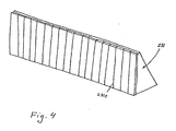
- Fig. 4 One possible design of forming such recesses is indicated in Fig. 4 , in which a piece 231 of the first insulating frame is shown. In the side which is intended to face the window frame side piece, the insulating frame piece 231 is provided with a number of weakening lines 231e in the height direction of the piece 231.
- the weakening lines 231e may e.g. be provided as perforations extending to a predetermined depth in the width direction of the insulating frame piece 231. It is to be understood that a corresponding section of the material of the insulating frame piece 231 is only fastened to the remaining section of the piece 231 along these weakening lines 231e.
- a suitable distance between the weakening lines 231e is chosen such that one or two sections of material between adjacent weakening lines 231e are torn away in order to provide a recess to accommodate the first leg 106a of the mounting bracket 106. It is of course also conceivable to form the insulating frame piece without potential recesses, and to form the recesses manually. Eventually, the insulating frame may be used without recesses altogether, even in the case of mounting brackets situated at the side pieces of the window frame.
- the pieces of the insulating frame or frames may be made from polyurethane foam or any other suitable material.
- the pieces of one insulating frame may e.g. be produced as a coherent string of extruded material that is cut into appropriate lengths.
Abstract
Description
- The present invention relates to a window for installation in an inclined roof surface according to the preamble of claim 1.
- Windows or other roof penetrating structures installed in roof surfaces are particularly exposed to thermal loss. In order to improve the overall insulating properties, insulation of at least a part of the outer side of the window frame has been suggested. In the prior art, this insulation has been carried out in a number of manners.
- For instance,
DE patent publication No. 38 37 377 ,EP 0744512 andWO 98/31896 -
EP patent No. 679773 - In all of the above arrangements, special precautions must normally be taken in order to secure a weathertight transition between the roof window and the surrounding roofing. In most cases, this entails an adaptation of the flashing and cover members, or the provision of customized parts, which render the manufacturing and installation more expensive.
- With this background it is an object of the present invention to provide a window of the kind mentioned in the introduction, in which the installation and utilisation conditions are improved, and which at the same time makes it possible to provide satisfactory insulating properties.
- In the invention, this and further objects are met by the provision of a window according to claim 1.
- By this design, a satisfactory balance has been found between the need for improving the insulating properties and considerations of installation and utilisation of the window. By forming the second leg of both the cover member and the flashing member with a predetermined angle corresponding to the angle of the second side of the insulating frame piece, the position of the window with respect to the plane of the roof may be adjusted, as these second legs may be displaced with respect to each other.
- In an advantageous embodiment, the top portion of each insulating frame piece of said first insulating frame is positioned substantially in the plane of the upper side of the window frame piece. This provides for an optimum enclosure of the frame, which is insulated up to its maximum height.
- In order to secure that humidity that for any reason is gathered under the flashing and/or cover is able to be drained off, the second leg of the flashing member and the second leg of the cover member may be positioned at a distance from the second side of the insulating frame piece of said first insulating frame. This allows for air to circulate in the gap thus formed.
- According to the installation conditions and the desired overall appearance of the window, the predetermined angle may range from 45 to 80°, and is preferably 60-70°.
- In order to improve the insulating properties , a second insulating frame is provide. Each piece of said second insulating frame extends from at least the lower side of the window frame piece substantially up to the bottom portion of the insulating frame piece of said first insulating frame. The insulating effect may be improved even further by a further development of this embodiment, in which a third insulating frame is provided, preferably also a fourth insulating frame.
- In an embodiment, which is particularly advantageous with respect to the installation conditions, a plurality of flashing corner members is provided for connection of adjoining flashing members.
- The water resulting from rain or other precipitation should be able to flow freely along the sides of the window and further out on the underlying roofing. In an embodiment, in which this property is insured in a particularly simple manner, the first leg of the flashing members has a predetermined width.
- The flashing and the cover may be provided as separate items, however, in an embodiment which is particularly advantageous with respect to delivery and installation conditions, the second leg of each flashing member and the second leg of each cover member are connected with each other. This effect is improved even further, if the connection is made integral.
- The material of the insulating frame may in principle be any suitable material possessing good insulating properties. Preferably, the insulating frame is made from polyurethane foam, which is easy to prepare and handle.
- Advantageous embodiments are set forth in the dependent claims.
- In the following the invention will be described in further detail with reference to the schematic drawings, in which
-
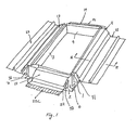
Fig. 1 is an exploded perspective view of a window, -
Fig. 2 is a cross-sectional view, on a larger scale, of the window ofFig. 1 along the line II-II, -
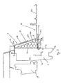
Fig. 3 is a view corresponding toFig. 2 of an embodiment of the window with a second insulating frame according to the invention, and -
Fig. 4 is a perspective view of insulating frames. - The window shown in the drawings comprises a window frame having a plurality of frame pieces. In all windows shown in the drawings, the window is rectangular and the window frame comprises four
frame pieces 1, 2, 3, 4, as shown in the windows ofFigs. 1 and2 , and the right-hand frame piece 101 only is visible inFig. 3 . The window furthermore comprises a window sash, which is openable with respect to the window frame. The right-handsash piece 5 and 105, respectively, is shown inFigs. 2 and3 . In the following, only the right-hand side frame piece of the window frame and the elements associated with this frame piece will be described in further detail. It is noted that this description applies, with any necessary modifications, to the other frame pieces and the elements associated to these pieces. - Referring now to
Figs. 1 and2 , the frame piece 1 has an upper side 1a, a lower side 1b, an outer side 1c and an inner side 1b. A height direction A is defined by a direction extending from the lower side 1b to the upper side 1a, and a width direction B is defined by a direction extending from the inner side 1d to the outer side 1c. The window is secured to the underlying roof structure (not shown) bymounting brackets 6 and 7 positioned at the corners between adjoining frame pieces, i.e. as shown between theframe pieces mounting brackets 6,7 rest on and are secured to the laths and/or rafters of the underlying roof structure. - A set of cover members 11-14 is provided for protection of the window frame against the weathering. The cover member 11 of the right-hand frame piece 1 has a first leg 11a for covering the upper side 1a of the frame piece 1 and a second leg 11b extending at an angle with respect to the first leg 11a and covering a part of the outer side 1c of the frame piece 1.
- In order to provide a weather-tight transition between the window and the surrounding roofing (not shown), a flashing frame is provided. In the window shown, the flashing frame includes four flashing members 21-24. The right-hand flashing member 21 has a first leg 21a lying substantially in the plane of the roof and a second leg 21b extending at an angle with respect to the first leg 21a. The second leg 21b is partly overlapped by the second leg 11b of the corresponding cover member 11. At the intersection between adjoining flashing members, the flashing members may be connected with each other in any suitable manner, e.g. by folding, welding or by any other method. Furthermore, a plurality of flashing corner members may be provided for connection of adjoining flashing members. In order to secure that water gathered at the top of the window is led down along the sides of the window and further down to the roofing below the window, possibly via a
skirt 22c which in a manner known per se is connected with the flashingmember 22, the first leg 21a of the flashing members should have a predetermined width, preferably such a width that corresponds to standard flashing members. This entails that the flashing members protrude a slight distance further out from the window in comparison with windows having standard flashings, where the first and second legs are substantially parallel with each other. - In order to improve the overall insulating properties of the window, a kit of insulating frames is provided. Such a kit may be provided separately, e.g. in a packaging separate from the window, or in connection with the window. As will be described in further detail in the following, the kit according to the invention comprises at least a first insulating frame.
- The first insulating frame includes a plurality of insulating frame pieces. In
Fig. 1 , only the right-hand and left-hand side insulatingframe pieces frame piece 32 are visible. The right-hand side insulatingframe piece 31 has a first side 31a facing the window frame piece 1 and a second side 31b facing the flashing member 21 and the cover member 11. Theinsulating frame piece 31 has a bottom portion 31c having a predetermined maximum width w and positioned substantially in the plane of the first leg 21a of the flashing member 21. In the embodiment shown, theinsulating frame 31 has a substantially triangular cross-section and ends in atop portion 31d substantially in the plane of upper side 1a of the window frame piece 1. The first side 31a should have such a height that a relatively large portion of the window piece is overlapped by the insulating frame piece. In the window shown, the window frame piece 1 is surrounded by insulation over substantially the whole height above themounting bracket 6. Generally, the width between the first side 31a and the second side 31b decreases from the maximum width w in a direction parallel with the height direction A such that the second side 31b forms a predetermined angle a other than perpendicular with the bottom portion 31c. The angle a may suitable lie in the interval of 45-80°, preferably 60-70°, in the window shown approx. 70°. - The second leg 11b of the flashing member 11 and the second leg 21b of the cover member 21 each extends substantially in parallel with the second side 31b of the insulating
frame piece 31. In the window shown, the second leg 21b of the flashing member and the second leg 11b of the cover member are positioned at a distance d from the second side 31b of the insulatingframe piece 31. This makes it possible to let air circulate in the space provided. The second leg 21b of each flashing member 21 and the second leg 11b of each cover member 11 may be connected with each other, e.g. integrally. It is advantageously possible to adjust the position of the flashing member and the cover member in order to accommodate different thicknesses of the roofing and/or the under roof, which may affect the position of the flashing in relation to the window and thus the cover. - In order to insulate also the area of the window frame situated below the plane defined by the respective bottom parts of the frame pieces of the first insulating frame, a second, third and/or fourth insulating frame may be provided as indicated in
Fig. 3 . In the embodiment ofFig. 3 , parts having similar and analogous function as corresponding parts inFigs. 1 and2 are denoted by the same reference numerals to which 100 has been added. - The second insulating frame, represented by its right-
hand member 141, may have any suitable configuration, but is advantageously an insulating frame as defined in Applicant'sEP patent application No. 1061199 A1 . In the embodiment shown, thepiece 141 of the second insulating frame extends from at least the lower side of the window frame piece 101b substantially up to the bottom portion 131c of the insulatingframe piece 131, in the installation situation in question up to the mountingbracket 106. The second insulating frame may have such width that the desired insulating properties below the level of the mounting brackets are attained by the second insulating frame alone. - However, the kit of insulating frames may also incorporate a third and a fourth insulating frame, of which
frame pieces 151 and 161, respectively, are shown inFig. 3 . The respective cross-section of the second, third and fourth insulating frame pieces may as indicated be chosen such that a solid trapezoid shape is obtained. Other shapes are conceivable as well, including those in which spaces are provided in between individual pieces. The outwards facing section of the contour, here represented by the outer side 151b of the third insulating frame piece 151, is chosen such that a good connection with the surroundinginsulation 170 is easily obtained. - The pieces of the insulating frames extend over substantially the entire length of the window frame piece. In case the window frame is secured to the underlying roof structure by means of mounting brackets positioned at the corners, the pieces of the first insulating frame may meet in any kind of joint, e.g. mitred joints. The pieces of the second, third and/or fourth insulating frames may have a length slightly shortened with respect to the corresponding piece of the first insulating frame.
- In the embodiment of
Fig. 3 , the window frame is secured to the underlying roof structure by means of angular mountingbrackets 106 which are attached to the side pieces of the window frame by means of a first leg 106a. In order to accommodate the leg 106a fastened to the side piece of the frame, the pieces of the first insulating frame may, at least at the side pieces, be provided with recesses. One possible design of forming such recesses is indicated inFig. 4 , in which apiece 231 of the first insulating frame is shown. In the side which is intended to face the window frame side piece, the insulatingframe piece 231 is provided with a number ofweakening lines 231e in the height direction of thepiece 231. Theweakening lines 231e may e.g. be provided as perforations extending to a predetermined depth in the width direction of the insulatingframe piece 231. It is to be understood that a corresponding section of the material of the insulatingframe piece 231 is only fastened to the remaining section of thepiece 231 along these weakeninglines 231e. A suitable distance between the weakeninglines 231e is chosen such that one or two sections of material betweenadjacent weakening lines 231e are torn away in order to provide a recess to accommodate the first leg 106a of the mountingbracket 106. It is of course also conceivable to form the insulating frame piece without potential recesses, and to form the recesses manually. Eventually, the insulating frame may be used without recesses altogether, even in the case of mounting brackets situated at the side pieces of the window frame. - The pieces of the insulating frame or frames may be made from polyurethane foam or any other suitable material. The pieces of one insulating frame may e.g. be produced as a coherent string of extruded material that is cut into appropriate lengths.
- The invention should not be regarded as being limited to the embodiment shown, but various modifications and combinations may be carried out within the scope of the claims.
Claims (14)
- A window for installation in an inclined roof surface, comprising
a window frame having a plurality of frame pieces (101), each frame piece having an upper side, a lower side, an inner side and an outer side, a height direction being defined by a direction extending from the lower side to the upper side,
mounting brackets for securing the window frame to the roof,
a set of cover members (111), each cover member having a first leg (111a) for covering the upper side of a respective frame piece and a second leg (111b) extending at an angle with respect to the first leg and covering a part of the outer side of the frame piece (101),
a flashing frame (121) including flashing members, each flashing member having a first leg (121a) lying substantially in the plane of the roof and a second leg (121b) extending at an angle with respect to the first leg, said second leg being at least partly overlapped by the second leg of the corresponding cover member,
a kit of insulating frames (131, 141) consisting of at least two insulating frames each including a plurality of insulating frame pieces extending over substantially the entire length of the window frame pieces, where a first insulating frame (131) of said kit of frames having insulating frame pieces with a first side (131a) facing the window frame piece (101) and a second side (131b) facing the flashing member and/or cover member, characterised in that
each insulating frame piece of said first insulating frame has a bottom portion having a predetermined maximum width and positioned substantially in the plane of the first leg of the flashing member the width between the first side (131a) and the second side (131b) decreasing from said maximum width in the height direction of the insulating frame piece (101) such that the second side (131b) forms a predetermined angle (α) other than perpendicular with the bottom portion (131c), and that
the second leg (121b) of the flashing member and the second leg (111b) of the cover member each extends substantially in parallel with the second side (131b) of the insulating frame piece (131),
and that the second insulating frame (141) of said kit of frames has insulating frame, pieces each extending from at least the lower side (101b) of the window frame piece substantially up to the bottom portion (131c) of the insulating frame piece of said first insulating frame. - A window according to claim 1, in which the top portion of each insulating frame piece (131) of said first insulating frame is positioned substantially in the plane of the upper side of the window frame piece (101).
- A window according to claim 1 or 2, in which the second insulating frame (141) extends from at least the lower side (101b) of the window frame substantially up to the mounting brackets (106).
- A window according to any one of the preceding claims, in which said mounting brackets are angular and in which at least the side pieces of the first insulating frame is provided with recesses in order to accommodate a first leg (106a) of a mounting bracket (106), which first leg(106a)is fastened to the side piece of the frame.
- A window according to claim 4, in which the insulating frame piece (231), in the side facing the window frame side piece, is provided with a number of weakening lines (231e) in the height direction of the insulating frame piece, where a corresponding section of the material of the insulating frame piece (231) is only fastened to the remaining section of the insulating frame piece along these weakening lines, and where one or two sections of material between adjacent weakening lines (231e) may be torn away in order to provide a recess to accommodate the first leg (106a) of the mounting bracket(106)
- A window according to any of the preceding claims, in which the second leg (121b) of he flashing member and the second leg (111b) of the cover member are positioned at a distance from the second side (131b) of the insulating frame piece of said first insulating frame.
- A window according to any one of the preceding claims, in which said predetermined angle (α) is 45-80°, preferably 60-70°.
- A window according to any of the preceding claims, in which a third insulating frame (151) is provided, preferably also a fourth insulating frame (161).
- A window according to any one of the preceding claims, in which a plurality of flashing corner members is provided for connection of adjoining flashing members.
- A window according to any one of the preceding claims, in which the first leg (121a) of the flashing members has a predetermined width.
- A window according to any one of the preceding claims, in which the second leg (121b) of each flashing member and the second leg (111b) of each cover member are connected with each other.
- A window according to claim 11, in which said connection is made integral.
- A window according to any one of the preceding claim, in which the insulating frame is made from polyurethane foam or any other suitable material.
- An inclined roof structure with a window installed therein according to one of the preceeding claims
Priority Applications (2)
| Application Number | Priority Date | Filing Date | Title |
|---|---|---|---|
| PL08101421T PL1925761T3 (en) | 2003-12-30 | 2004-12-23 | Window and insulating frame kit |
| EP08101421A EP1925761B1 (en) | 2003-12-30 | 2004-12-23 | Window and insulating frame kit |
Applications Claiming Priority (3)
| Application Number | Priority Date | Filing Date | Title |
|---|---|---|---|
| EP03388091A EP1550777B1 (en) | 2003-12-30 | 2003-12-30 | Window |
| EP04803065A EP1706557B1 (en) | 2003-12-30 | 2004-12-23 | Window and insulating frame kit |
| EP08101421A EP1925761B1 (en) | 2003-12-30 | 2004-12-23 | Window and insulating frame kit |
Related Parent Applications (2)
| Application Number | Title | Priority Date | Filing Date |
|---|---|---|---|
| EP04803065.4 Division | 2004-12-23 | ||
| EP04803065A Division EP1706557B1 (en) | 2003-12-30 | 2004-12-23 | Window and insulating frame kit |
Publications (2)
| Publication Number | Publication Date |
|---|---|
| EP1925761A1 EP1925761A1 (en) | 2008-05-28 |
| EP1925761B1 true EP1925761B1 (en) | 2011-02-09 |
Family
ID=34560254
Family Applications (3)
| Application Number | Title | Priority Date | Filing Date |
|---|---|---|---|
| EP03388091A Expired - Lifetime EP1550777B1 (en) | 2003-12-30 | 2003-12-30 | Window |
| EP08101421A Not-in-force EP1925761B1 (en) | 2003-12-30 | 2004-12-23 | Window and insulating frame kit |
| EP04803065A Active EP1706557B1 (en) | 2003-12-30 | 2004-12-23 | Window and insulating frame kit |
Family Applications Before (1)
| Application Number | Title | Priority Date | Filing Date |
|---|---|---|---|
| EP03388091A Expired - Lifetime EP1550777B1 (en) | 2003-12-30 | 2003-12-30 | Window |
Family Applications After (1)
| Application Number | Title | Priority Date | Filing Date |
|---|---|---|---|
| EP04803065A Active EP1706557B1 (en) | 2003-12-30 | 2004-12-23 | Window and insulating frame kit |
Country Status (7)
| Country | Link |
|---|---|
| EP (3) | EP1550777B1 (en) |
| CN (1) | CN2782881Y (en) |
| AT (2) | ATE337449T1 (en) |
| DE (2) | DE60307869T2 (en) |
| DK (1) | DK1925761T3 (en) |
| PL (2) | PL1706557T3 (en) |
| WO (1) | WO2005064098A1 (en) |
Families Citing this family (16)
| Publication number | Priority date | Publication date | Assignee | Title |
|---|---|---|---|---|
| EP2273028B1 (en) * | 2005-06-30 | 2015-10-14 | VKR Holding A/S | An insulating frame for a roof window |
| DE102008055744B4 (en) * | 2008-11-04 | 2010-07-29 | Roto Frank Ag | Roof windows, in particular roof windows |
| EP2192248B1 (en) * | 2008-11-26 | 2015-07-15 | VKR Holding A/S | Roof component flashing, a flashing system and a method of flashing |
| DE102009004644A1 (en) * | 2009-01-28 | 2010-07-29 | Roto Frank Ag | Windows, in particular roof windows, with a mounting bracket |
| PL2466032T3 (en) * | 2010-12-17 | 2018-02-28 | Vkr Holding A/S | An insulating member comprising two elements of different material and a method for insulating a window in an inclined roof structure with this insulating member |
| DK177601B1 (en) * | 2013-01-07 | 2013-11-18 | Vkr Holding As | A gutter-like flashing member and a roof structure including such a flashing member |
| DE102014007702A1 (en) | 2014-05-22 | 2015-11-26 | Roto Frank Ag | Deck arrangement for a rooftop and roof with built-in roof windows and a Eindeckanordnung |
| DK179674B1 (en) * | 2015-02-26 | 2019-03-19 | Vkr Holding A/S | Window including a climate-shielding transition assembly |
| DK179827B1 (en) * | 2015-08-04 | 2019-07-17 | Vkr Holding A/S | An insulating member, a roof window and a method for insulating a roof window |
| DK201570503A1 (en) * | 2015-08-04 | 2017-02-27 | Vkr Holding As | Method for packaging a window with frame insulation and a packed window |
| DE102016008467B4 (en) * | 2016-07-12 | 2019-08-29 | Günther-Markus Renz | Manually sliding sliding roof window |
| DK179409B1 (en) * | 2017-05-16 | 2018-06-06 | Vkr Holding As | A flashing assembly and a method for weather proofing a roof window mounted in an inclined roof surface |
| DK179519B1 (en) * | 2017-05-16 | 2019-02-05 | Vkr Holding A/S | A roof window installed in an inclined roof structure with a flashing assembly and a method for weather proofing a roof window |
| EP3594426A1 (en) * | 2018-07-09 | 2020-01-15 | VKR Holding A/S | An under flashing corner element; kits of elements; and a method of flashing a lower part of a roof element |
| EP3656943A1 (en) | 2018-11-20 | 2020-05-27 | VKR Holding A/S | A method of installation of an insulation frame in a roof window, an insulation frame for use in the same and a kit for installation |
| EP3779085B1 (en) * | 2020-02-03 | 2024-01-24 | VKR Holding A/S | A skylight window |
Family Cites Families (7)
| Publication number | Priority date | Publication date | Assignee | Title |
|---|---|---|---|---|
| DE3837377C2 (en) | 1988-11-03 | 1994-10-06 | Reinhard Fuhrmann | Flat roof insulation wedge |
| DE9406932U1 (en) | 1994-04-26 | 1994-06-16 | Roto Frank Ag | Feed box |
| DE19518853A1 (en) | 1995-05-23 | 1996-11-28 | Puren Schaumstoff Gmbh | Insulating part for roof window frames |
| DE19653007A1 (en) * | 1996-12-19 | 1998-06-25 | Markus Kueble | Skylight |
| ATE222982T1 (en) | 1997-01-14 | 2002-09-15 | Vkr Holding As | INSULATION AND INSTALLATION FRAME FOR A SKYLIGHT AND METHOD FOR INSTALLING A SKYLIGHT WITH SUCH FRAME |
| DK199900873A (en) | 1999-06-18 | 2001-04-02 | Vkr Holding As | Insulation frame for a skylight |
| DE20203854U1 (en) * | 2002-03-11 | 2002-07-18 | Schlott Wolfgang | Insulation frame for roof windows |
-
2003
- 2003-12-30 EP EP03388091A patent/EP1550777B1/en not_active Expired - Lifetime
- 2003-12-30 AT AT03388091T patent/ATE337449T1/en not_active IP Right Cessation
- 2003-12-30 DE DE60307869T patent/DE60307869T2/en not_active Expired - Lifetime
-
2004
- 2004-12-23 DE DE602004031388T patent/DE602004031388D1/en active Active
- 2004-12-23 PL PL04803065T patent/PL1706557T3/en unknown
- 2004-12-23 EP EP08101421A patent/EP1925761B1/en not_active Not-in-force
- 2004-12-23 EP EP04803065A patent/EP1706557B1/en active Active
- 2004-12-23 PL PL08101421T patent/PL1925761T3/en unknown
- 2004-12-23 AT AT08101421T patent/ATE498043T1/en not_active IP Right Cessation
- 2004-12-23 DK DK08101421.9T patent/DK1925761T3/en active
- 2004-12-23 WO PCT/DK2004/000915 patent/WO2005064098A1/en active IP Right Grant
- 2004-12-29 CN CNU2004201218725U patent/CN2782881Y/en not_active Expired - Lifetime
Also Published As
| Publication number | Publication date |
|---|---|
| ATE337449T1 (en) | 2006-09-15 |
| DE60307869T2 (en) | 2007-04-12 |
| ATE498043T1 (en) | 2011-02-15 |
| EP1706557A1 (en) | 2006-10-04 |
| EP1550777B1 (en) | 2006-08-23 |
| DK1925761T3 (en) | 2011-05-23 |
| EP1706557B1 (en) | 2008-07-16 |
| PL1925761T3 (en) | 2011-07-29 |
| DE60307869D1 (en) | 2006-10-05 |
| PL1706557T3 (en) | 2009-01-30 |
| EP1550777A1 (en) | 2005-07-06 |
| WO2005064098A1 (en) | 2005-07-14 |
| EP1925761A1 (en) | 2008-05-28 |
| DE602004031388D1 (en) | 2011-03-24 |
| CN2782881Y (en) | 2006-05-24 |
Similar Documents
| Publication | Publication Date | Title |
|---|---|---|
| EP1925761B1 (en) | Window and insulating frame kit | |
| EP1070182B1 (en) | Flashing member and frame for a roof-penetrating building part | |
| HU227050B1 (en) | Insulating frame for skylight window | |
| EP1579093B1 (en) | Flashing member with adaptable corner segments | |
| CZ292664B6 (en) | Flashing member and flashing frame | |
| EP1567732B1 (en) | A flashing device and a method of installing a roof penetrating structure by means of the flashing device | |
| JP4183085B2 (en) | Eaves structure with ventilation function | |
| WO2011044906A1 (en) | A window construction and a method for mounting the window construction | |
| DK179519B1 (en) | A roof window installed in an inclined roof structure with a flashing assembly and a method for weather proofing a roof window | |
| EP3404161B1 (en) | A flashing assembly and a method for weather proofing a roof window mounted in an inclined roof surface | |
| CN1152188C (en) | Frame structure | |
| EP3795771B1 (en) | Skylight window | |
| JPH0311292Y2 (en) | ||
| JP2599080B2 (en) | Keraba gable | |
| JP3147348B2 (en) | Fixing structure of decorative plate for parapet | |
| JP2511639B2 (en) | Building ventilation structure | |
| JP3072231U (en) | Cover of the joint between the building structure and the Kasagi | |
| JP2021143573A (en) | Drainer member and attachment structure for the same | |
| JP2021175848A (en) | Roof structure and cover member | |
| JP3945788B2 (en) | Bay window structure | |
| JPH031932Y2 (en) | ||
| JPH03156063A (en) | Eaves gap cover for roof and sealing plate mounting material | |
| CA2181378A1 (en) | Protective covering for building fascia | |
| JPH0368981B2 (en) | ||
| JPH0341617B2 (en) |
Legal Events
| Date | Code | Title | Description |
|---|---|---|---|
| PUAI | Public reference made under article 153(3) epc to a published international application that has entered the european phase |
Free format text: ORIGINAL CODE: 0009012 |
|
| AC | Divisional application: reference to earlier application |
Ref document number: 1706557 Country of ref document: EP Kind code of ref document: P |
|
| AK | Designated contracting states |
Kind code of ref document: A1 Designated state(s): IS LT PL |
|
| 17P | Request for examination filed |
Effective date: 20081127 |
|
| AKX | Designation fees paid |
Designated state(s): AT BE BG CH CY CZ DE DK EE ES FI FR GB GR HU IE IS IT LI LT LU MC NL PL PT RO SE SI SK TR |
|
| 17Q | First examination report despatched |
Effective date: 20090115 |
|
| GRAP | Despatch of communication of intention to grant a patent |
Free format text: ORIGINAL CODE: EPIDOSNIGR1 |
|
| GRAJ | Information related to disapproval of communication of intention to grant by the applicant or resumption of examination proceedings by the epo deleted |
Free format text: ORIGINAL CODE: EPIDOSDIGR1 |
|
| GRAP | Despatch of communication of intention to grant a patent |
Free format text: ORIGINAL CODE: EPIDOSNIGR1 |
|
| GRAS | Grant fee paid |
Free format text: ORIGINAL CODE: EPIDOSNIGR3 |
|
| GRAA | (expected) grant |
Free format text: ORIGINAL CODE: 0009210 |
|
| AC | Divisional application: reference to earlier application |
Ref document number: 1706557 Country of ref document: EP Kind code of ref document: P |
|
| AK | Designated contracting states |
Kind code of ref document: B1 Designated state(s): AT BE BG CH CY CZ DE DK EE ES FI FR GB GR HU IE IS IT LI LT LU MC NL PL PT RO SE SI SK TR |
|
| REG | Reference to a national code |
Ref country code: GB Ref legal event code: FG4D |
|
| REG | Reference to a national code |
Ref country code: CH Ref legal event code: EP |
|
| REG | Reference to a national code |
Ref country code: IE Ref legal event code: FG4D |
|
| REF | Corresponds to: |
Ref document number: 602004031388 Country of ref document: DE Date of ref document: 20110324 Kind code of ref document: P |
|
| REG | Reference to a national code |
Ref country code: DE Ref legal event code: R096 Ref document number: 602004031388 Country of ref document: DE Effective date: 20110324 |
|
| REG | Reference to a national code |
Ref country code: DK Ref legal event code: T3 |
|
| REG | Reference to a national code |
Ref country code: NL Ref legal event code: VDEP Effective date: 20110209 |
|
| LTIE | Lt: invalidation of european patent or patent extension |
Effective date: 20110209 |
|
| PG25 | Lapsed in a contracting state [announced via postgrant information from national office to epo] |
Ref country code: SE Free format text: LAPSE BECAUSE OF FAILURE TO SUBMIT A TRANSLATION OF THE DESCRIPTION OR TO PAY THE FEE WITHIN THE PRESCRIBED TIME-LIMIT Effective date: 20110209 Ref country code: GR Free format text: LAPSE BECAUSE OF FAILURE TO SUBMIT A TRANSLATION OF THE DESCRIPTION OR TO PAY THE FEE WITHIN THE PRESCRIBED TIME-LIMIT Effective date: 20110510 Ref country code: LT Free format text: LAPSE BECAUSE OF FAILURE TO SUBMIT A TRANSLATION OF THE DESCRIPTION OR TO PAY THE FEE WITHIN THE PRESCRIBED TIME-LIMIT Effective date: 20110209 |
|
| REG | Reference to a national code |
Ref country code: PL Ref legal event code: T3 |
|
| PG25 | Lapsed in a contracting state [announced via postgrant information from national office to epo] |
Ref country code: NL Free format text: LAPSE BECAUSE OF FAILURE TO SUBMIT A TRANSLATION OF THE DESCRIPTION OR TO PAY THE FEE WITHIN THE PRESCRIBED TIME-LIMIT Effective date: 20110209 Ref country code: FI Free format text: LAPSE BECAUSE OF FAILURE TO SUBMIT A TRANSLATION OF THE DESCRIPTION OR TO PAY THE FEE WITHIN THE PRESCRIBED TIME-LIMIT Effective date: 20110209 Ref country code: BG Free format text: LAPSE BECAUSE OF FAILURE TO SUBMIT A TRANSLATION OF THE DESCRIPTION OR TO PAY THE FEE WITHIN THE PRESCRIBED TIME-LIMIT Effective date: 20110509 Ref country code: SI Free format text: LAPSE BECAUSE OF FAILURE TO SUBMIT A TRANSLATION OF THE DESCRIPTION OR TO PAY THE FEE WITHIN THE PRESCRIBED TIME-LIMIT Effective date: 20110209 Ref country code: AT Free format text: LAPSE BECAUSE OF FAILURE TO SUBMIT A TRANSLATION OF THE DESCRIPTION OR TO PAY THE FEE WITHIN THE PRESCRIBED TIME-LIMIT Effective date: 20110209 Ref country code: CY Free format text: LAPSE BECAUSE OF FAILURE TO SUBMIT A TRANSLATION OF THE DESCRIPTION OR TO PAY THE FEE WITHIN THE PRESCRIBED TIME-LIMIT Effective date: 20110209 |
|
| PG25 | Lapsed in a contracting state [announced via postgrant information from national office to epo] |
Ref country code: EE Free format text: LAPSE BECAUSE OF FAILURE TO SUBMIT A TRANSLATION OF THE DESCRIPTION OR TO PAY THE FEE WITHIN THE PRESCRIBED TIME-LIMIT Effective date: 20110209 |
|
| PG25 | Lapsed in a contracting state [announced via postgrant information from national office to epo] |
Ref country code: RO Free format text: LAPSE BECAUSE OF FAILURE TO SUBMIT A TRANSLATION OF THE DESCRIPTION OR TO PAY THE FEE WITHIN THE PRESCRIBED TIME-LIMIT Effective date: 20110209 Ref country code: SK Free format text: LAPSE BECAUSE OF FAILURE TO SUBMIT A TRANSLATION OF THE DESCRIPTION OR TO PAY THE FEE WITHIN THE PRESCRIBED TIME-LIMIT Effective date: 20110209 |
|
| PLBE | No opposition filed within time limit |
Free format text: ORIGINAL CODE: 0009261 |
|
| STAA | Information on the status of an ep patent application or granted ep patent |
Free format text: STATUS: NO OPPOSITION FILED WITHIN TIME LIMIT |
|
| 26N | No opposition filed |
Effective date: 20111110 |
|
| REG | Reference to a national code |
Ref country code: DE Ref legal event code: R097 Ref document number: 602004031388 Country of ref document: DE Effective date: 20111110 |
|
| PG25 | Lapsed in a contracting state [announced via postgrant information from national office to epo] |
Ref country code: IT Free format text: LAPSE BECAUSE OF FAILURE TO SUBMIT A TRANSLATION OF THE DESCRIPTION OR TO PAY THE FEE WITHIN THE PRESCRIBED TIME-LIMIT Effective date: 20110209 |
|
| PG25 | Lapsed in a contracting state [announced via postgrant information from national office to epo] |
Ref country code: MC Free format text: LAPSE BECAUSE OF NON-PAYMENT OF DUE FEES Effective date: 20111231 |
|
| REG | Reference to a national code |
Ref country code: IE Ref legal event code: MM4A |
|
| PG25 | Lapsed in a contracting state [announced via postgrant information from national office to epo] |
Ref country code: IE Free format text: LAPSE BECAUSE OF NON-PAYMENT OF DUE FEES Effective date: 20111223 |
|
| PG25 | Lapsed in a contracting state [announced via postgrant information from national office to epo] |
Ref country code: LU Free format text: LAPSE BECAUSE OF NON-PAYMENT OF DUE FEES Effective date: 20111223 |
|
| PG25 | Lapsed in a contracting state [announced via postgrant information from national office to epo] |
Ref country code: IS Free format text: LAPSE BECAUSE OF FAILURE TO SUBMIT A TRANSLATION OF THE DESCRIPTION OR TO PAY THE FEE WITHIN THE PRESCRIBED TIME-LIMIT Effective date: 20110209 |
|
| PG25 | Lapsed in a contracting state [announced via postgrant information from national office to epo] |
Ref country code: TR Free format text: LAPSE BECAUSE OF FAILURE TO SUBMIT A TRANSLATION OF THE DESCRIPTION OR TO PAY THE FEE WITHIN THE PRESCRIBED TIME-LIMIT Effective date: 20110209 |
|
| PG25 | Lapsed in a contracting state [announced via postgrant information from national office to epo] |
Ref country code: ES Free format text: LAPSE BECAUSE OF FAILURE TO SUBMIT A TRANSLATION OF THE DESCRIPTION OR TO PAY THE FEE WITHIN THE PRESCRIBED TIME-LIMIT Effective date: 20110520 Ref country code: HU Free format text: LAPSE BECAUSE OF FAILURE TO SUBMIT A TRANSLATION OF THE DESCRIPTION OR TO PAY THE FEE WITHIN THE PRESCRIBED TIME-LIMIT Effective date: 20110209 |
|
| PG25 | Lapsed in a contracting state [announced via postgrant information from national office to epo] |
Ref country code: ES Free format text: LAPSE BECAUSE OF FAILURE TO SUBMIT A TRANSLATION OF THE DESCRIPTION OR TO PAY THE FEE WITHIN THE PRESCRIBED TIME-LIMIT Effective date: 20110209 |
|
| PG25 | Lapsed in a contracting state [announced via postgrant information from national office to epo] |
Ref country code: PT Free format text: LAPSE BECAUSE OF FAILURE TO SUBMIT A TRANSLATION OF THE DESCRIPTION OR TO PAY THE FEE WITHIN THE PRESCRIBED TIME-LIMIT Effective date: 20110209 |
|
| REG | Reference to a national code |
Ref country code: FR Ref legal event code: PLFP Year of fee payment: 12 |
|
| REG | Reference to a national code |
Ref country code: FR Ref legal event code: PLFP Year of fee payment: 13 |
|
| REG | Reference to a national code |
Ref country code: FR Ref legal event code: PLFP Year of fee payment: 14 |
|
| PGFP | Annual fee paid to national office [announced via postgrant information from national office to epo] |
Ref country code: DK Payment date: 20171212 Year of fee payment: 14 |
|
| REG | Reference to a national code |
Ref country code: DK Ref legal event code: EBP Effective date: 20181231 |
|
| PG25 | Lapsed in a contracting state [announced via postgrant information from national office to epo] |
Ref country code: DK Free format text: LAPSE BECAUSE OF NON-PAYMENT OF DUE FEES Effective date: 20181231 |
|
| PGFP | Annual fee paid to national office [announced via postgrant information from national office to epo] |
Ref country code: CZ Payment date: 20191126 Year of fee payment: 16 Ref country code: DE Payment date: 20191210 Year of fee payment: 16 |
|
| PGFP | Annual fee paid to national office [announced via postgrant information from national office to epo] |
Ref country code: CH Payment date: 20191213 Year of fee payment: 16 |
|
| PGFP | Annual fee paid to national office [announced via postgrant information from national office to epo] |
Ref country code: GB Payment date: 20191219 Year of fee payment: 16 |
|
| PGFP | Annual fee paid to national office [announced via postgrant information from national office to epo] |
Ref country code: FR Payment date: 20201125 Year of fee payment: 17 |
|
| PGFP | Annual fee paid to national office [announced via postgrant information from national office to epo] |
Ref country code: PL Payment date: 20201118 Year of fee payment: 17 Ref country code: BE Payment date: 20201116 Year of fee payment: 17 |
|
| REG | Reference to a national code |
Ref country code: DE Ref legal event code: R119 Ref document number: 602004031388 Country of ref document: DE |
|
| PG25 | Lapsed in a contracting state [announced via postgrant information from national office to epo] |
Ref country code: CZ Free format text: LAPSE BECAUSE OF NON-PAYMENT OF DUE FEES Effective date: 20201223 |
|
| REG | Reference to a national code |
Ref country code: CH Ref legal event code: PL |
|
| GBPC | Gb: european patent ceased through non-payment of renewal fee |
Effective date: 20201223 |
|
| PG25 | Lapsed in a contracting state [announced via postgrant information from national office to epo] |
Ref country code: LI Free format text: LAPSE BECAUSE OF NON-PAYMENT OF DUE FEES Effective date: 20201231 Ref country code: GB Free format text: LAPSE BECAUSE OF NON-PAYMENT OF DUE FEES Effective date: 20201223 Ref country code: DE Free format text: LAPSE BECAUSE OF NON-PAYMENT OF DUE FEES Effective date: 20210701 Ref country code: CH Free format text: LAPSE BECAUSE OF NON-PAYMENT OF DUE FEES Effective date: 20201231 |
|
| REG | Reference to a national code |
Ref country code: BE Ref legal event code: MM Effective date: 20211231 |
|
| PG25 | Lapsed in a contracting state [announced via postgrant information from national office to epo] |
Ref country code: FR Free format text: LAPSE BECAUSE OF NON-PAYMENT OF DUE FEES Effective date: 20211231 Ref country code: BE Free format text: LAPSE BECAUSE OF NON-PAYMENT OF DUE FEES Effective date: 20211231 |
|
| PG25 | Lapsed in a contracting state [announced via postgrant information from national office to epo] |
Ref country code: PL Free format text: LAPSE BECAUSE OF NON-PAYMENT OF DUE FEES Effective date: 20211223 |