EP1925540A2 - Auxiliary drive for a trailer - Google Patents
Auxiliary drive for a trailer Download PDFInfo
- Publication number
- EP1925540A2 EP1925540A2 EP08004824A EP08004824A EP1925540A2 EP 1925540 A2 EP1925540 A2 EP 1925540A2 EP 08004824 A EP08004824 A EP 08004824A EP 08004824 A EP08004824 A EP 08004824A EP 1925540 A2 EP1925540 A2 EP 1925540A2
- Authority
- EP
- European Patent Office
- Prior art keywords
- drive
- carrier
- auxiliary
- trailer
- movement
- Prior art date
- Legal status (The legal status is an assumption and is not a legal conclusion. Google has not performed a legal analysis and makes no representation as to the accuracy of the status listed.)
- Granted
Links
- 230000033001 locomotion Effects 0.000 claims abstract description 140
- 230000007246 mechanism Effects 0.000 claims abstract description 57
- 230000005540 biological transmission Effects 0.000 claims abstract description 25
- 238000004146 energy storage Methods 0.000 abstract description 20
- 230000000284 resting effect Effects 0.000 abstract 1
- 230000000694 effects Effects 0.000 description 16
- 230000009471 action Effects 0.000 description 7
- 210000000629 knee joint Anatomy 0.000 description 7
- 241001295925 Gegenes Species 0.000 description 5
- 238000006073 displacement reaction Methods 0.000 description 5
- 238000000034 method Methods 0.000 description 5
- 230000008569 process Effects 0.000 description 5
- 230000008859 change Effects 0.000 description 4
- 239000000969 carrier Substances 0.000 description 3
- 230000002441 reversible effect Effects 0.000 description 3
- 210000003127 knee Anatomy 0.000 description 2
- 238000006243 chemical reaction Methods 0.000 description 1
- 238000010586 diagram Methods 0.000 description 1
- 239000012530 fluid Substances 0.000 description 1
- 230000036544 posture Effects 0.000 description 1
- 230000004044 response Effects 0.000 description 1
Images


Classifications
-
- B—PERFORMING OPERATIONS; TRANSPORTING
- B60—VEHICLES IN GENERAL
- B60S—SERVICING, CLEANING, REPAIRING, SUPPORTING, LIFTING, OR MANOEUVRING OF VEHICLES, NOT OTHERWISE PROVIDED FOR
- B60S9/00—Ground-engaging vehicle fittings for supporting, lifting, or manoeuvring the vehicle, wholly or in part, e.g. built-in jacks
- B60S9/14—Ground-engaging vehicle fittings for supporting, lifting, or manoeuvring the vehicle, wholly or in part, e.g. built-in jacks for both lifting and manoeuvring
- B60S9/205—Power driven manoeuvring fittings, e.g. reciprocably driven steppers or rotatably driven cams
- B60S9/21—Power driven manoeuvring fittings, e.g. reciprocably driven steppers or rotatably driven cams comprising a rotatably driven auxiliary wheel or endless track, e.g. driven by ground wheel
- B60S9/215—Power driven manoeuvring fittings, e.g. reciprocably driven steppers or rotatably driven cams comprising a rotatably driven auxiliary wheel or endless track, e.g. driven by ground wheel driven by an auxiliary motor
-
- B—PERFORMING OPERATIONS; TRANSPORTING
- B62—LAND VEHICLES FOR TRAVELLING OTHERWISE THAN ON RAILS
- B62D—MOTOR VEHICLES; TRAILERS
- B62D59/00—Trailers with driven ground wheels or the like
- B62D59/04—Trailers with driven ground wheels or the like driven from propulsion unit on trailer
Definitions
- the invention relates to an auxiliary drive for a trailer, in particular for a caravan.
- Trailers are usually towed by tractors. So it is known that a car can pull a caravan. When the trailer is removed from the tractor, it is usually pushed by hand to the final position.
- trailers are increasingly offered in the caravan area, which can be moved only with difficulty by hand because of their size and thus their weight. Therefore, auxiliary drives have been developed which make it possible to move or turn a trailer with engine assistance even without a tractor.
- An auxiliary drive for a trailer is known in which a frame part is firmly connected to the chassis of the trailer.
- the frame part carries a relative to the frame part movable carrier, of which in turn a drive motor is held with a drivable by the drive motor drive roller.
- a moving mechanism is provided for moving the carrier between a rest position in which the drive roller is separated from a tire of the trailer, and a drive position in which the drive roller is pressed against the tire of the carrier.
- the change in the position of the carrier is done manually by means of a lever which can be attached to the carrier.
- the pivoting of the carrier from the rest position to the drive position is usually in cooperation with a toggle mechanism, which ensures that the carrier in the respective end position, i. the drive or the rest position is locked.
- the carrier is pivoted by means of an actuating lever or a crank. Due to the high forces required to overcome the toggle mechanism, correspondingly large pivot angles are required for an actuating lever. Nevertheless, it can not be prevented that the respective end position of the carrier after overcoming the middle position of the toggle mechanism is achieved only with great force and usually jerky. Not only is this stressful for the operator, it also carries the risk of the operator pinching his fingers. If the carrier is to be pivoted by means of a crank drive, it is necessary for the operator to operate a crank that is usually difficult to reach, for which he must move to the squat position. Due to the gear ratio of crank drives it is difficult for him to clearly recognize the respective end positions. As a result, there is a risk that the drive roller is not pressed with sufficient pressure force on the running surface of the wheel to be driven by the trailer and in the attempt to move the trailer, crazy.
- a wheeled vehicle which is driven by an electric motor via a drive wheel.
- the drive wheel is mounted on a carrier and movable between a drive position and a rest position.
- EP 1 447 312 A1 describes an auxiliary drive for trailers, with two motor-driven drive rollers, which are held by a carrier.
- the carrier is movable relative to the chassis. For this purpose, a drive movement is transmitted via a lever system.
- the invention has for its object to provide an auxiliary drive for a trailer, in which the movement of the carrier between its rest position and the drive position is comfortably possible, so that the operator is particularly protected against unfavorable postures or excessive use of force.
- a moving mechanism for moving the carrier between a rest position in which the drive roller is separated from a wheel of the trailer, and a drive position in which the drive roller is pressed against the wheel of the trailer.
- the movement mechanism has an analogous to the positions of the carrier between a rest position and a drive position movable manual actuating element, such as an actuating lever, whose movement is transmitted via the movement mechanism to the carrier.
- the movement mechanism has an energy store, wherein the energy store can be charged during a first movement section of the manual actuation element, while the energy store is during a second movement section of the manual actuation element is dischargeable to assist the movement of the wearer.
- the second movement section is in the movement process when moving the manual actuating element from the rest position to the drive position.
- the first movement section comprises at least a part of the movement area in which the wearer is still moved freely away from the tire in the direction of the tire or without a hindering force effect.
- the energy store releases the energy stored in it and thereby supports the movement of the carrier, namely in particular when the carrier has to press the drive roller against the running surface of the wheel.
- the released energy can also be used to e.g. lower the maximum force required to overcome a toggle effect.
- the second movement section at least partially comprises the part of the movement in which the drive roller is pressed against the tire.
- the second movement section may also comprise other movement areas, such as, in particular, overcoming a toggle mechanism.
- the first movement section that is to say the movement section in which the energy store is charged or, if it has already been preloaded, continues to be charged in the movement process when the manual actuating element is moved from the drive position into the rest position.
- the energy is stored permanently and stands in the reverse movement, ie when moving the carrier from the rest position to the drive position, again available.
- the movement of the manual control element is divided into two parts: First, the manual control element must be moved with increased force to charge the energy storage. This is not a problem because during the first movement section still no increased forces to overcome the toggle mechanism or for pressing the drive roller against the tire are required.
- the operator can press or pull over the entire path of movement of the manual actuating element with almost constant force.
- the end positions of the manual actuating element he receives the information about the respective end position of the carrier.
- the energy storage device comprises a spring device with e.g. a screw or a leaf spring, which makes it possible to store the energy in a simple manner over a longer period of time without significant losses.
- a spring device with e.g. a screw or a leaf spring, which makes it possible to store the energy in a simple manner over a longer period of time without significant losses.
- the toggle mechanism is movable against the action of the spring means.
- the spring device should advantageously act on the knee of the toggle mechanism.
- the movement mechanism has a moveable cam disk interacting with the energy store (the spring device), such that different cam positions result in different states of charge of the energy store (spring deflection).
- the spring can be tensioned during the first movement section and, with a corresponding design, relaxed in the second movement section, so that the spring assists a corresponding rotation of the cam disk.
- the movement mechanism comprises a transmission mechanism with a variable over the path of movement of the manual actuator transmission effect, such that a certain path of the hand actuator causes different lengths of movement of the carrier, depending on whether the manual control element and the carrier closer to the rest position or closer to the drive position.
- the transmission mechanism allows the "gear ratio" between the movement of the manual actuator and the movement of the carrier to be variable.
- An equally long movement path (displacement or pivoting) of the manual actuating element in this way causes different lengths of movement paths, depending on the area in which this movement path of the manual actuating element is completed.
- an equally long movement path of the manual actuating element in the vicinity of the rest position causes a greater movement path of the carrier than in the vicinity of the drive position.
- the carrier usually only has to be displaced, with the actuating force only having to overcome the unavoidable friction.
- the manual operation force must not only press the drive roller sufficiently against the tread of the tire, but also overcome, for example, a toggle mechanism.
- the transmission mechanism permits different transmission effects, ie different transmission ratios or lever effects
- a slight movement of the manual actuating element can already be sufficient in the vicinity of the rest position, ie in the region in which no high forces are required for moving the carrier to achieve appropriate movement of the wearer.
- a first transfer ratio is formed between the movement of the hand-operated member and the movement of the wearer, such that a given travel of the hand-operated member causes a first travel of the wearer
- a second movement portion is formed a second transmission ratio between the movement of the manual actuating element and the movement of the carrier, such that the determined movement path of the manual actuating element causes a second path of movement of the carrier.
- the second movement section at least partially comprises the part of the movement in which the drive roller is pressed against the tire, and that the second movement path of the carrier is shorter than the first movement path of the carrier.
- the transmission mechanism has a cam track, e.g. has in the form of an eccentric or a sliding guide.
- the auxiliary drive is not equipped with a manual operating element. Rather, the movement mechanism has a servo drive to move the carrier between the rest position and the drive position.
- the servo drive eliminates the need for manual operation.
- the operator can use the e.g. remotely controlled servo drive move the carrier in the respective desired position.
- the servo drive comprises an electric, electro-hydraulic, electromagnetic, hydraulic, hydro-pneumatic or pneumatic actuator on.
- the power supply can be taken over by a battery present in the trailer or by its own power supply.
- a hydraulic actuator and a hydraulic motor can be used which receives pressurized hydraulic fluid from a corresponding pump.
- the servo drive has an electric auxiliary motor, preferably with a transmission.
- the transmission has a spindle drive with a high transmission ratio.
- the spindle drive allows the motor to operate at relatively high speeds but low torque and thus to be relatively small in size.
- the chassis of the trailer on at least two wheels each wheel is assigned a separate drive motor and a separate drive roller.
- the servo drive has only one common auxiliary motor, with the same time both drive motors and both drive rollers, so both carriers between the rest position and the drive position can be moved.
- the auxiliary motor is in this case preferably to be arranged in the middle between the two wheels.
- the direction of movement of the carrier can be varied as desired.
- the carrier is movable substantially radially and / or linearly to the tire of the trailer.
- the drive roller can be pivoted to the tread of the tire.
- it is pivotable in a pivot plane, wherein the pivot plane is either perpendicular to an axis of rotation of the tire, the axis of rotation itself includes, or is at an angle to a plane comprising the axis of rotation.
- a locking device is provided for locking the carrier relative to the frame part at least in the drive position. This ensures that the drive roller is pressed with the required pressure force against the tread of the tire.
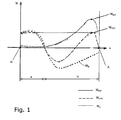
- Fig. 1 shows several torque curves for explaining a first principle of action.
- a manual actuator e.g. an actuating lever in response to the pivot angle ⁇ act.
- the torque curve is shown as a solid line, which usually acts on the actuating lever, when the lever is pivoted by the operator from the rest position R to the drive position A.
- the operator only has to apply low forces, since only a small amount of torque is required.
- the required torque M IST increases sharply, on the one hand to overcome, for example, the middle or zero position of a toggle mechanism and on the other hand to generate a sufficiently large pressure force with which the drive roller is pressed against the wheel of the trailer. After overcoming the maximum, the torque then drops to zero, because the actuating lever stops in its end position (drive position A).
- an energy storage is connected to the actuating lever, which is charged in a first movement section a by the pivoting of the actuating lever.
- the first movement section a therefore represents a certain pivoting angle ⁇ lying in the vicinity of the rest position R.
- a second movement section b adjoins, during which the energy store discharges again and therefore supports the further rotational movement of the actuating lever.
- the torque acting through the energy storage is represented as a dotted line M E.
- the torque M E is positive, so that the energy storage is charged, while the torque curve M E in the second movement section b in the negative region, so that the energy storage itself contributes to the torque effect and supports the movement of the actuating lever.
- the torque M OPT is again in the positive range, so that the operator can easily move the operating lever into the drive position.
- Fig. 1 shows the torque curves only as an example to explain the principle.
- the optimized torque M OPT it may be desirable for the optimized torque M OPT never to become negative, so that the operator must always press the operating lever in one direction only and not have to hold in the opposite direction.
- the energy content of the energy store during loading and unloading - neglected any friction losses - must be the same, which in Fig. 1 not fully expressed.
- a bias of the energy storage is taken into account.
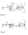
- Fig. 2 schematically shows an auxiliary drive for a trailer.
- the trailer has a chassis 1, usually carried by one or two axles becomes.
- On the axles wheels are mounted in a known manner, in Fig. 2 a tire of a wheel 2 is shown in fragmentary form.
- the auxiliary drive has a rigidly connected to the chassis 1 frame part, which may of course also be the chassis 1 itself in the frame part. It is only crucial that the auxiliary drive can be supported on the chassis 1 and accordingly there is a rigid connection to the chassis 1.
- a carrier 3 is held movable.
- the carrier has a slot 4 which slides over a pin 5.
- the pin 5 is rigidly connected to the chassis 1 and holds in this way the carrier.
- a drive roller 6 is rotatably supported, which in turn is driven by a drive motor, not shown.
- the drive motor may e.g. be switched on and off via a remote control or by appropriate wiring.
- Fig. 2 The embodiment of Fig. 2 is shown only schematically.
- the carrier 3, together with the drive motor and the drive roller in the example in the EP 0 827 898 A1 or the EP 1 203 713 B1 be constructed described manner.
- Fig. 2 only the principle of action should be presented.
- the drive roller 6 is separated from the wheel 2.
- the drive roller 6 is located together with the carrier 3 in an intermediate position between the rest position and drive position.
- Fig. 3 shown the same auxiliary drive, but in the drive position in which the drive roller 6 presses against the wheel 2.
- the position of the carrier 3 with the drive roller 6 and the drive motor, not shown, is changed by means of an actuating lever 7 serving as a manual actuating element.
- the operating lever 7 may consist of the in Fig. 2 shown intermediate position in the Fig. 3 shown drive position or be moved to a rest position not shown.
- the actuating lever 7 is part of a movement mechanism, which also has a cam 8 coupled to the lever, a push rod 9 and a leaf spring 10 serving as energy storage.
- the actuating lever 7 is pivotable about an axis 11 together with the cam 8.
- the leaf spring 10 in relation to the rest position R from Fig. 2 more relaxed and thus saves less energy.
- the leaf spring 10 Upon retraction of the carrier 3, however, by pivoting the actuating lever 7, the leaf spring 10 is deflected stronger due to the shape of the cam 8 and takes the in Fig. 2 shown position.
- the leaf spring 10 stores energy.
- the operator must accordingly exert an increased force on the operating lever 7 in order to generate the required torque.
- the energy remains stored in the leaf spring 10 until the operator again pivots the operating lever 7 in the opposite direction to move the carrier 3 to the driving position.
- the leaf spring 10 outputs the stored energy and generates on the cam 8, a torque that is converted into a force that supports the movement of the carrier 3, so that the force to be applied by the operator on the operating lever 7 is lower.
- the cam 8 is given a spiral outer contour in order to remove the force action point between the leaf spring 10 and the cam 8 with respect to its distance and its position from the axis 11 and to achieve a change in the effective torque.
- the carrier 3 can also be moved in any other way by means of a linear guide or about a pivot axis (arranged vertically or horizontally). However, this has no effect on the invention. So it is easily possible that in the FIGS. 2 and 3 shown support 3 instead of linearly pivoted about the pin 5 about a fixed vertical or horizontal axis by means of the push rod 9.
- Fig. 4 indicates in an analogous manner Fig. 1 the torque curve, wherein the solid line represents the torque M IST , which would occur if the movement mechanism would have no energy storage in the form of the leaf spring 10.
- the dotted line M E shows that the torque resulting from the energy stored in the leaf spring 10, while with M OPT the torque applied by the operator to the operating lever 7 by his hand force is shown.
- Fig. 4 - as Fig. 1 - only an exemplary qualitative representation.
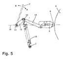
- Fig. 5 an embodiment is shown in which the carrier 3 with the drive roller 2 substantially in connection with the FIGS. 2 and 3 described carrier 3 corresponds.
- the movement mechanism used in this embodiment also has the actuating lever 7 pivotable about the axis 11. With the actuating lever 7, a first link 12 is fixedly connected, which is connected via a knee joint 13 to a second link 14. The second link 14 then leads to the carrier 3 and moves it in the required manner.
- the drive roller 6 is just before its drive position A. However, it does not touch the tread of the tire 2 yet. Rather, the operating lever 7 would have to be pressed further in the direction of the arrow A, so that the knee joint 13 about its zero position (angle between first link 12 and second link 14 is 180 °; Kniehebeltot Vietnamese) is pushed through. Only when the knee joint 13 is below a reference line 16, the drive roller 6 reaches its drive position. Of course, further pivoting of the knee joint 13 must be avoided by a suitable stop.
- the toggle dead center with spring 15 thus also serves to reliably detect the end position (rest position).
- the movement of the knee joint 13 beyond the reference line 16 is supported by the prestressed coil spring 15. This makes it easier for the operator to not only press the knee joint 13 by its zero position, but at the same time to provide the required contact pressure for the drive roller 6 against the tire 2.
- the coil spring 15 When swinging back the operating lever 7 to move the carrier 3 in its rest position R, the coil spring 15, however, is stretched and can store in this way the required energy.
- the coil spring 15 is able to hold the energy over a longer period of time (days, months) and release it only when needed.
- Fig. 6 an embodiment is shown in which the moving mechanism instead of an energy storage device has a transmission mechanism, the transmission effect is variable in dependence on the pivotal position of the serving as a manual operating element operating lever.
- a guide member 17 is fixedly connected to the actuating lever 7, which is also pivotable about the axis 11.
- the guide element 17 preferably carries a roller 18 which is movable along a curve guide 19 connected to the carrier 3. Instead of the cam guide 19 and a closed link guide can be selected.
- the roller 18 also pulls back the carrier 3 when the operating lever 7 is pivoted back into the rest position R, so that the drive roller 6 is separated from the tire 2 becomes.
- the carrier 3 can also be withdrawn by a spring device from the drive position to the rest position.
- cam guide 19 has different radii of curvature. This makes it possible that in a first movement section, in which the operator does not yet have to apply large forces, a relatively rapid movement of the carrier 3 achieved, while in the area in which the operator would normally apply a high operating force, by designing the Curve guide 19 larger pivoting paths of the actuating lever 7 only cause minor displacement or pivoting paths of the carrier 3. In this way, it is possible to change the transmission effect or the transmission ratio of the movement mechanism during the pivoting of the actuating lever 7 - depending on its absolute position.
- Fig. 7 shows the associated torque curves, where M IST again the torque is shown, which would occur if the movement mechanism would not be configured in the inventive way, while M OPT shows the dashed line the improved, ie equalized torque curve. It can be seen that the maximum torque at M OPT is significantly below the previously occurring maximum torque of the curve M actual .
- FIG. 9 show an embodiment of the invention, wherein Fig. 9 an excerpt from Fig. 8 is.
- a servo drive 20 is arranged, which is held by a cross member also serving as a torque arm 21.
- Fig. 9 shows, the servo drive 20 to an electric assist motor 22 which rotatably drives a Anschwenkstange 24 via a gear 23.
- the auxiliary engine 22 and the transmission 23 may form a motor-gear unit.
- the direction of rotation of the auxiliary motor 22 is reversible, so that the Anschwenkstange 24 can be rotated in both directions.
- the Anschwenkstange 24 is guided on both sides outwards to the wheels 2, so that there the respective associated carrier 3 can be pivoted between its rest position and its drive position.
- the Anschwenkstange 24 can be mounted parallel to the cross member 1, but also within the cross member 21.
- a servo drive 25 may be provided, which is mounted only on one side of the chassis 1 and its rotation still on the Anschwenkstange 24 to the opposite carrier of the other wheel 2 is transmitted. It is also possible that each carrier 3 is assigned a single servo drive 25 to pivot the carrier 3 between the rest position and the drive position.
- Fig. 10 shows as a variant of an embodiment of the invention, in which the servo drive is formed by a motor-gear unit 26 which is held on the chassis 1 and a spindle 27 rotatably drives. With the help of the spindle 27, the carrier 3 is linearly reciprocated between its rest position and its drive position.
- FIG. 11 An embodiment of the invention is in Fig. 11 and as a detail enlargement in Fig. 12 shown.
- a held or supported by the chassis 1 servo drive 28 drives - designed as a motor-gear unit - on both sides réelleckende Anschwenkspindeln 29 and 29 'at.
- Each spindle 29, 29 ' is connected in each case via a lever 30a and via a parallel guide 30 with a carrier 3, which can be displaced parallel by the parallel guide 30 relative to the chassis 1 accordingly.
- the servo drive 28 rotates the Anschwenkspindeln 29 and 29 ', on which the levers 30a move in a correspondingly guided manner.
- the carriers 3 are displaced parallel outwards in each case.
- the drive roller 6 When the drive roller 6 has reached the running surface of the wheel 2, it must be further pressed against the wheel 2 in order to achieve a sufficient friction effect can. Due to the parallel guide 30, however, the drive roller 6 is moved not only radially to the wheel 2, but also axially, whereby in the contact surface between the drive roller 6 and the running surface of the wheel 2 an erasing effect occurs, which can damage the tread.
- a slot 32 is formed in the carrier 3, in which the parallel guide 30 engages.
- Fig. 12 shows, is a belonging to the parallel guide 30 pin 33 initially in a rear portion of the slot 32.
- An axial displacement of the carrier 3 together with the drive roller 6 does not take place. Rather, the carrier 3 and the drive roller 6 are only attracted radially in the direction of the wheel 2 until they have reached the drive position.
- Servo drives so far only auxiliary electric motors have been described.
- servo drives are provided in which the required movement of the carrier is achieved by means of an actuator.
- electric, electro-hydraulic, electromagnetic, hydraulic, hydro-pneumatic or pneumatic actuators are suitable.
- a pneumatic actuator may e.g. be operated by a conventional camping compressor, which otherwise for filling air mattresses, etc. is used. The compressor must be connected to the pneumatic actuator only if the position of the carrier 3 is to be changed.
- a locking device is provided with which at least the drive position of the carrier, but preferably also the rest position of the carrier can be securely held.
- locking means are latch, locking devices or toggle mechanisms, such as from the EP 0 827 898 A1 known.
- the carrier in almost any way between the rest position and the drive position.
- the carrier can also be pivoted laterally, radially or axially about arbitrarily arranged axes. In this way, it is possible that the carrier is parked in its rest position in a protected area below or within the landing gear, where it is housed protected in the normal process of the trailer with a tractor without being able to take damage.
- various forms of movement such as pivoting or linear displacement can be combined with each other to achieve the desired path of movement of the wearer.
- An arresting device can be provided for locking the carrier relative to the frame part at least in the drive position.
Abstract
Description
Die Erfindung betrifft einen Hilfsantrieb für einen Anhänger, insbesondere für einen Wohnwagen.The invention relates to an auxiliary drive for a trailer, in particular for a caravan.
Anhänger werden üblicherweise von Zugmaschinen gezogen. So ist es bekannt, dass ein PKW einen Wohnwagen ziehen kann. Wenn der Anhänger von der Zugmaschine abgenommen ist, wird er üblicherweise von Hand in die endgültige Position geschoben. Jedoch werden heutzutage zunehmend Anhänger im Wohnwagenbereich angeboten, die aufgrund ihrer Größe und damit ihres Gewichts nur noch unter Mühen von Hand verschoben werden können. Daher wurden Hilfsantriebe entwickelt, die es ermöglichen, auch ohne Zugmaschine einen Anhänger mit Motorunterstützung zu verschieben bzw. zu drehen.Trailers are usually towed by tractors. So it is known that a car can pull a caravan. When the trailer is removed from the tractor, it is usually pushed by hand to the final position. However, nowadays trailers are increasingly offered in the caravan area, which can be moved only with difficulty by hand because of their size and thus their weight. Therefore, auxiliary drives have been developed which make it possible to move or turn a trailer with engine assistance even without a tractor.
Aus der
In der
Das Verschwenken des Trägers aus der Ruheposition in die Antriebsposition erfolgt meist in Zusammenwirken mit einem Kniehebelmechanismus, der sicherstellt, dass der Träger in der jeweiligen Endstellung, d.h. der Antriebs- oder der Ruheposition arretiert ist.The pivoting of the carrier from the rest position to the drive position is usually in cooperation with a toggle mechanism, which ensures that the carrier in the respective end position, i. the drive or the rest position is locked.
Der Träger wird mit Hilfe eines Betätigungshebels oder einer Kurbel verschwenkt. Aufgrund der zum Überwinden des Kniehebelmechanismus erforderlichen hohen Kräfte sind entsprechend große Schwenkwinkel für einen Betätigungshebel erforderlich. Trotzdem lässt es sich nicht verhindern, dass die jeweilige Endlage des Trägers nach Überwinden der Mittelstellung des Kniehebelmechanismus nur mit großem Krafteinsatz und meist ruckartig erreicht wird. Dies ist für den Bediener nicht nur anstrengend, sondern birgt auch die Gefahr in sich, dass der Bediener seine Finger einklemmt. Wenn der Träger mit Hilfe eines Kurbelantriebs verschwenkt werden soll, ist es erforderlich, dass der Bediener eine meist schlecht erreichbare Kurbel betätigt, wozu er sich in die Hockstellung begeben muss. Aufgrund des Übersetzungsverhältnisses bei Kurbelantrieben ist es für ihn dabei schwierig, die jeweiligen Endstellungen klar zu erkennen. Dadurch besteht die Gefahr, dass die Antriebswalze nicht mit ausreichender Druckkraft an die Lauffläche des von ihr anzutreibenden Rads des Anhängers angedrückt wird und bei dem Versuch, den Anhänger zu verfahren, durchdreht.The carrier is pivoted by means of an actuating lever or a crank. Due to the high forces required to overcome the toggle mechanism, correspondingly large pivot angles are required for an actuating lever. Nevertheless, it can not be prevented that the respective end position of the carrier after overcoming the middle position of the toggle mechanism is achieved only with great force and usually jerky. Not only is this stressful for the operator, it also carries the risk of the operator pinching his fingers. If the carrier is to be pivoted by means of a crank drive, it is necessary for the operator to operate a crank that is usually difficult to reach, for which he must move to the squat position. Due to the gear ratio of crank drives it is difficult for him to clearly recognize the respective end positions. As a result, there is a risk that the drive roller is not pressed with sufficient pressure force on the running surface of the wheel to be driven by the trailer and in the attempt to move the trailer, crazy.
Aus der
In der
Der Erfindung liegt die Aufgabe zugrunde, einen Hilfsantrieb für einen Anhänger anzugeben, bei dem das Bewegen des Trägers zwischen seiner Ruheposition und der Antriebsposition komfortabel möglich ist, sodass der Bediener insbesondere vor ungünstigen Körperhaltungen oder übermäßigem Krafteinsatz bewahrt wird.The invention has for its object to provide an auxiliary drive for a trailer, in which the movement of the carrier between its rest position and the drive position is comfortably possible, so that the operator is particularly protected against unfavorable postures or excessive use of force.
Die Aufgabe wird erfindungsgemäß durch einen Hilfsantrieb für einen Anhänger gemäß einem der Patentansprüche 1 oder 2 gelöst.The object is achieved by an auxiliary drive for a trailer according to one of the
Bei einem Hilfsantrieb ist ein Bewegungsmechanismus vorgesehen, zum Bewegen des Trägers zwischen einer Ruheposition, in der die Antriebswalze von einem Rad des Anhängers getrennt ist, und einer Antriebsposition, in der die Antriebswalze gegen das Rad des Anhängers gedrückt wird. Der Bewegungsmechanismus weist ein analog zu den Positionen des Trägers zwischen einer Ruheposition und einer Antriebsposition bewegbares Handbetätigungselement, wie z.B. einen Betätigungshebel, auf, dessen Bewegung über den Bewegungsmechanismus auf den Träger übertragen wird. Erfindungsgemäß weist der Bewegungsmechanismus einen Energiespeicher auf, wobei der Energiespeicher während eines ersten Bewegungsabschnitts des Handbetätigungselements aufladbar ist, während der Energiespeicher während eines zweiten Bewegungsabschnitts des Handbetätigungselements entladbar ist, um die Bewegung des Trägers zu unterstützen. Dabei liegt der zweite Bewegungsabschnitt in dem Bewegungsvorgang beim Bewegen des Handbetätigungselements aus der Ruheposition in die Antriebsposition.In an auxiliary drive, a moving mechanism is provided for moving the carrier between a rest position in which the drive roller is separated from a wheel of the trailer, and a drive position in which the drive roller is pressed against the wheel of the trailer. The movement mechanism has an analogous to the positions of the carrier between a rest position and a drive position movable manual actuating element, such as an actuating lever, whose movement is transmitted via the movement mechanism to the carrier. According to the invention, the movement mechanism has an energy store, wherein the energy store can be charged during a first movement section of the manual actuation element, while the energy store is during a second movement section of the manual actuation element is dischargeable to assist the movement of the wearer. In this case, the second movement section is in the movement process when moving the manual actuating element from the rest position to the drive position.
Es ist somit möglich, dass der Bediener während des ersten Bewegungsabschnitts das Handbetätigungselement mit größerer Kraft betätigt als es zum Bewegen des Trägers alleine erforderlich wäre. Der erste Bewegungsabschnitt umfasst dementsprechend wenigstens einen Teil des Bewegungsbereichs, in dem der Träger noch frei in Richtung des Reifens oder ohne hindernde Kraftwirkung von dem Reifen weg bewegt wird.It is thus possible for the operator, during the first movement section, to operate the manual operating element with a greater force than would be required to move the carrier alone. Accordingly, the first movement section comprises at least a part of the movement area in which the wearer is still moved freely away from the tire in the direction of the tire or without a hindering force effect.
In dem zweiten Bewegungsabschnitt hingegen gibt der Energiespeicher die in ihm gespeicherte Energie ab und unterstützt dadurch die Bewegung des Trägers, nämlich insbesondere dann, wenn der Träger die Antriebswalze gegen die Lauffläche des Rads drücken muss. Ebenso kann die frei werdende Energie auch genutzt werden, um z.B. die zum Überwinden eines Kniehebeleffekts erforderliche Maximalkraft abzusenken.In the second movement section, however, the energy store releases the energy stored in it and thereby supports the movement of the carrier, namely in particular when the carrier has to press the drive roller against the running surface of the wheel. Likewise, the released energy can also be used to e.g. lower the maximum force required to overcome a toggle effect.
Auf diese Weise ist es möglich, die vom Bediener aufzubringende Betätigungskraft zu vergleichmäßigen bzw. bisher insbesondere bei Kniehebelmechanismen auftretende Spitzenkräfte zu mindern. Der Bediener muss nicht - wie bisher - den Bedienhebel zunächst über einen gewissen Bereich ohne großen Widerstand bewegen, um anschließend mit sehr hoher Kraft den Kniehebelmechanismus zu überwinden. Vielmehr kann er mit gleichmäßiger Betätigungskraft den Bedienhebel (Handbetätigungselement) aus der Ruheposition in die Antriebsposition bewegen.In this way, it is possible to even out the actuation force to be applied by the operator or to reduce peak forces that have hitherto occurred, especially in the case of toggle lever mechanisms. The operator does not have to - as before - move the operating lever over a certain range without much resistance in order to then overcome the toggle mechanism with very high force. Rather, he can move the operating lever (manual control element) from the rest position to the drive position with uniform operating force.
Vorzugsweise umfasst daher der zweite Bewegungsabschnitt wenigstens teilweise den Teil der Bewegung, bei dem die Antriebswalze gegen den Reifen gedrückt wird. Selbstverständlich kann der zweite Bewegungsabschnitt auch andere Bewegungsbereiche, wie insbesondere das Überwinden eines Kniehebelmechanismus, umfassen.Preferably, therefore, the second movement section at least partially comprises the part of the movement in which the drive roller is pressed against the tire. Of course, the second movement section may also comprise other movement areas, such as, in particular, overcoming a toggle mechanism.
Bei einem Hilfsantrieb liegt der erste Bewegungsabschnitt, also der Bewegungsabschnitt, bei dem der Energiespeicher aufgeladen bzw. - sofern er bereits vorgeladen ist - weiter aufgeladen wird, in dem Bewegungsvorgang beim Bewegen des Handbetätigungselements aus der Antriebsposition in die Ruheposition. Das bedeutet, dass der Energiespeicher dann aufgeladen wird, wenn der Träger von dem Reifen wegbewegt wird, um in seine Ruheposition zu gelangen. Die Energie wird dauerhaft gespeichert und steht bei der umgekehrten Bewegung, also beim Bewegen des Trägers aus der Ruheposition in die Antriebsposition, wieder zur Verfügung.In the case of an auxiliary drive, the first movement section, that is to say the movement section in which the energy store is charged or, if it has already been preloaded, continues to be charged in the movement process when the manual actuating element is moved from the drive position into the rest position. This means that the energy storage is then charged when the carrier is moved away from the tire to reach its rest position. The energy is stored permanently and stands in the reverse movement, ie when moving the carrier from the rest position to the drive position, again available.
Bei einer anderen Ausführungsform liegt der erste Bewegungsabschnitt in dem Bewegungsvorgang beim Bewegen des Handbetätigungselements aus der Ruheposition in die Antriebsposition, jedoch vor dem zweiten Bewegungsabschnitt, sodass das Handbetätigungselement beim Bewegen aus der Ruheposition in die Antriebsposition zuerst den ersten Bewegungsabschnitt und danach den zweiten Bewegungsabschnitt passiert. Bei dieser Variante wird die Bewegung des Handbetätigungselements zweigeteilt: Zunächst muss das Handbetätigungselement mit erhöhter Kraft bewegt werden, um den Energiespeicher aufzuladen. Dies ist unproblematisch, weil während des ersten Bewegungsabschnitts noch keine erhöhten Kräfte zum Überwinden des Kniehebelmechanismus oder zum Andrücken der Antriebswalze gegen den Reifen erforderlich sind. Wenn jedoch bei der weiteren Bewegung des Handbetätigungselements vom Bediener bei bisher bekannten Hilfsantrieben die erhöhte Bedienkraft abverlangt würde, um den Kniehebel zu überwinden oder die Antriebswalze an den Reifen anzudrücken, entlädt sich jetzt erfindungsgemäß der Energiespeicher und bewirkt eine Kraft, die der Bedienkraft überlagert wird und sie dadurch unterstützt. Dementsprechend kann der Bediener mit im Vergleich zum Stand der Technik geringerer Kraft drücken.In another embodiment, the first movement portion in the moving operation when moving the manual operation member from the rest position to the drive position, but before the second movement portion, so that the manual operation element when moving from the rest position to the drive position first passes the first movement section and then the second movement section. In this variant, the movement of the manual control element is divided into two parts: First, the manual control element must be moved with increased force to charge the energy storage. This is not a problem because during the first movement section still no increased forces to overcome the toggle mechanism or for pressing the drive roller against the tire are required. However, if in the further movement of the manual actuator by the operator in previously known auxiliary drives, the increased operating force would be required to overcome the toggle or press the drive roller to the tire, discharges now according to the invention, the energy storage and causes a force that is superimposed on the operator and she supports it. Accordingly, the operator can press with less force compared to the prior art.
Bei entsprechender Auslegung des Bewegungsmechanismus ist es möglich, dass der Bediener über den gesamten Bewegungsweg des Handbetätigungselements mit nahezu konstanter Kraft drücken bzw. ziehen kann. Durch die Endstellungen des Handbetätigungselements erhält er die Information über die jeweilige Endstellung des Trägers. Eine Rückmeldung über das Überwinden des Kniehebelmechanismus oder das Andrücken der Antriebswalze gegen den Reifen erhält der Bediener jedoch dann nicht, wenn die bisher auftretenden erhöhten Reaktionskräfte durch den Energiespeicher vollständig kompensiert werden.With an appropriate design of the movement mechanism, it is possible that the operator can press or pull over the entire path of movement of the manual actuating element with almost constant force. Through the end positions of the manual actuating element he receives the information about the respective end position of the carrier. A feedback on the overcoming of the toggle mechanism or the pressing of the drive roller against the tire, however, the operator does not receive when the previously occurring increased reaction forces are completely compensated by the energy storage.
Vorzugsweise weist der Energiespeicher eine Federeinrichtung mit z.B. einer Schrauben- oder einer Blattfeder auf, die es ermöglicht, die Energie in einfacher Weise auch über einen längeren Zeitraum ohne nennenswerte Verluste zu speichern.Preferably, the energy storage device comprises a spring device with e.g. a screw or a leaf spring, which makes it possible to store the energy in a simple manner over a longer period of time without significant losses.
Wenn der Bewegungsmechanismus einen Kniehebelmechanismus aufweist, ist es vorteilhaft, wenn der Kniehebelmechanismus gegen die Wirkung der Federeinrichtung bewegbar ist. Die Federeinrichtung sollte dabei vorteilhafterweise am Knie des Kniehebelmechanismus wirken.When the moving mechanism has a toggle mechanism, it is advantageous if the toggle mechanism is movable against the action of the spring means. The spring device should advantageously act on the knee of the toggle mechanism.
Bei einer anderen Ausführungsform weist der Bewegungsmechanismus eine mit dem Energiespeicher (der Federeinrichtung) zusammen wirkende, bewegbare Kurvenscheibe auf, derart, dass unterschiedliche Kurvenscheiben-Stellungen unterschiedliche Ladezustände des Energiespeichers (Federauslenkung) bewirken. Dadurch kann mit Hilfe der Kurvenscheibe die Feder während des ersten Bewegungsabschnitts gespannt und - bei entsprechender Gestaltung - in dem zweiten Bewegungsabschnitt entspannt werden, sodass die Feder eine entsprechende Drehung der Kurvenscheibe unterstützt.In another embodiment, the movement mechanism has a moveable cam disk interacting with the energy store (the spring device), such that different cam positions result in different states of charge of the energy store (spring deflection). As a result, with the aid of the cam disk, the spring can be tensioned during the first movement section and, with a corresponding design, relaxed in the second movement section, so that the spring assists a corresponding rotation of the cam disk.
Be einer Variante weist der Bewegungsmechanismus einen Übertragungsmechanismus auf, mit einer über den Bewegungsweg des Handbetätigungselements veränderlichen Übertragungswirkung, derart, dass ein bestimmter Bewegungsweg des Handbetätigungselements unterschiedlich lange Bewegungswege des Trägers bewirkt, je nachdem, ob sich das Handbetätigungselement und der Träger näher bei der Ruheposition oder näher bei der Antriebsposition befinden.In a variant, the movement mechanism comprises a transmission mechanism with a variable over the path of movement of the manual actuator transmission effect, such that a certain path of the hand actuator causes different lengths of movement of the carrier, depending on whether the manual control element and the carrier closer to the rest position or closer to the drive position.
Der Übertragungsmechanismus ermöglicht es, dass das "Übersetzungsverhältnis" zwischen der Bewegung des Handbetätigungselements und der Bewegung des Trägers veränderlich ist. Ein gleich langer Bewegungsweg (Verschieben oder Verschwenken) des Handbetätigungselements bewirkt auf diese Weise unterschiedlich lange Bewegungswege, je nachdem, in welchem Bereich dieser Bewegungsweg des Handbetätigungselements vollzogen wird.The transmission mechanism allows the "gear ratio" between the movement of the manual actuator and the movement of the carrier to be variable. An equally long movement path (displacement or pivoting) of the manual actuating element in this way causes different lengths of movement paths, depending on the area in which this movement path of the manual actuating element is completed.
Besonders vorteilhaft ist es, wenn ein gleich langer Bewegungsweg des Handbetätigungselements in der Nähe der Ruheposition einen größeren Bewegungsweg des Trägers bewirkt als in der Nähe der Antriebsposition. Im Bereich der Ruheposition nämlich muss der Träger üblicherweise nur verschoben werden, wobei die Betätigungskraft lediglich die nicht zu vermeidende Reibung überwinden muss. In der Nähe der Antriebsposition hingegen muss die Handbetätigungskraft nicht nur die Antriebswalze in ausreichendem Maße gegen die Lauffläche des Reifens drücken, sondern z.B. auch einen Kniehebelmechanismus überwinden. Dadurch, dass der Übertragungsmechanismus unterschiedliche Übertragungswirkungen, d.h. unterschiedliche Übersetzungsverhältnisse bzw. Hebelwirkungen ermöglicht, kann in der Nähe der Ruheposition, also in dem Bereich, in dem keine hohen Kräfte zum Bewegen des Trägers erforderlich sind, bereits eine geringe Bewegung des Handbetätigungselements ausreichen, um eine entsprechende Bewegung des Trägers zu erreichen. In der Nähe der Antriebsposition hingegen ist es zur Vergleichmäßigung der Betätigungskraft für den Bediener anzustreben, dass der Träger bei entsprechend gleichem Bewegungsweg des Handbetätigungselements eine geringere, insbesondere kürzere Bewegung vollzieht, wodurch die auf das Handbetätigungselement rückwirkenden Kräfte geringer werden.It is particularly advantageous if an equally long movement path of the manual actuating element in the vicinity of the rest position causes a greater movement path of the carrier than in the vicinity of the drive position. In the area of the rest position, the carrier usually only has to be displaced, with the actuating force only having to overcome the unavoidable friction. In the vicinity of the drive position, on the other hand, the manual operation force must not only press the drive roller sufficiently against the tread of the tire, but also overcome, for example, a toggle mechanism. By virtue of the fact that the transmission mechanism permits different transmission effects, ie different transmission ratios or lever effects, a slight movement of the manual actuating element can already be sufficient in the vicinity of the rest position, ie in the region in which no high forces are required for moving the carrier to achieve appropriate movement of the wearer. In the vicinity of the drive position, however, it is desirable to equalize the operating force for the operator that the carrier in accordance with the same path of movement of the manual actuating element performs a smaller, in particular shorter movement, whereby the forces acting on the manual actuating element are reduced.
Bei einer Ausführungsform wird beim Bewegen des Handbetätigungselements aus der Ruheposition in die Antriebsposition in einem ersten Bewegungsabschnitt ein erstes Übertragungsverhältnis zwischen der Bewegung des Handbetätigungselements und der Bewegung des Trägers gebildet, derart, dass ein bestimmter Bewegungsweg des Handbetätigungselements einen ersten Bewegungsweg des Trägers bewirkt, wobei in einem zweiten Bewegungsabschnitt ein zweites Übertragungsverhältnis zwischen der Bewegung des Handbetätigungselements und der Bewegung des Trägers gebildet wird, derart, dass der bestimmte Bewegungsweg des Handbetätigungselements einen zweiten Bewegungsweg des Trägers bewirkt. Diese Definition bestätigt das oben bereits Vorgetragene, wonach bei gleichen Bewegungswegen des Handbetätigungselements (allerdings aus verschiedenen Ausgangsstellungen heraus) unterschiedliche Bewegungswege des Trägers erreicht werden.In one embodiment, as the hand-operated member is moved from the rest position to the drive position in a first movement portion, a first transfer ratio is formed between the movement of the hand-operated member and the movement of the wearer, such that a given travel of the hand-operated member causes a first travel of the wearer, in FIG a second movement portion is formed a second transmission ratio between the movement of the manual actuating element and the movement of the carrier, such that the determined movement path of the manual actuating element causes a second path of movement of the carrier. This definition confirms what has already been said above, according to which different movement paths of the wearer are achieved with the same movement paths of the manual actuation element (but from different initial positions).
Dabei ist es vorteilhaft, dass der zweite Bewegungsabschnitt wenigstens teilweise den Teil der Bewegung umfasst, bei dem die Antriebswalze gegen den Reifen gedrückt wird, und dass der zweite Bewegungsweg des Trägers kürzer als der erste Bewegungsweg des Trägers ist.In this case, it is advantageous that the second movement section at least partially comprises the part of the movement in which the drive roller is pressed against the tire, and that the second movement path of the carrier is shorter than the first movement path of the carrier.
Um die gewünschte Veränderung des Übertragungsverhältnisses der Bewegung zu erreichen, ist es von besonderem Vorteil, wenn der Übertragungsmechanismus eine Kurvenführung, z.B. in Form eines Exzenters oder einer Kulissenführung aufweist.In order to achieve the desired change in the transmission ratio of the movement, it is particularly advantageous if the transmission mechanism has a cam track, e.g. has in the form of an eccentric or a sliding guide.
Bei in den Ansprüchen 1 und 2 definierten Varianten ist der Hilfsantrieb nicht mit einem Handbetätigungselement ausgestattet. Vielmehr weist der Bewegungsmechanismus einen Servoantrieb auf, um den Träger zwischen der Ruheposition und der Antriebsposition zu bewegen.In the variants defined in
Durch den Servoantrieb wird eine manuelle Betätigung überflüssig. Der Bediener kann mit Hilfe des z.B. fernsteuerbaren Servoantriebs den Träger in die jeweils gewünschte Position verfahren.The servo drive eliminates the need for manual operation. The operator can use the e.g. remotely controlled servo drive move the carrier in the respective desired position.
Vorzugsweise weist der Servoantrieb ein elektrisches, elektrohydraulisches, elektromagnetisches, hydraulisches, hydro-pneumatisches oder pneumatisches Stellglied auf. Die Energieversorgung kann durch eine in dem Anhänger vorhandene Batterie oder durch eine eigene Energieversorgung übernommen werden. Z.B. ist es dabei möglich, das pneumatische Stellglied mit Hilfe einer elektrischen Camping-Luftpumpe zu betreiben, die ansonsten für andere Zwecke eingesetzt wird. Nur dann, wenn der Bediener den Hilfsantrieb benötigt, wird die elektrisch betriebene Luftpumpe zum Aktivieren des pneumatischen Stellglieds betätigt.Preferably, the servo drive comprises an electric, electro-hydraulic, electromagnetic, hydraulic, hydro-pneumatic or pneumatic actuator on. The power supply can be taken over by a battery present in the trailer or by its own power supply. For example, it is possible to operate the pneumatic actuator using an electric camping air pump, which is otherwise used for other purposes. Only when the operator needs the auxiliary drive, the electrically operated air pump is actuated to activate the pneumatic actuator.
Als hydraulisches Stellglied kann auch ein Hydromotor verwendet werden, der unter Druck stehende Hydraulikflüssigkeit von einer entsprechenden Pumpe erhält.As a hydraulic actuator and a hydraulic motor can be used which receives pressurized hydraulic fluid from a corresponding pump.
Besonders vorteilhaft ist es, wenn der Servoantrieb einen elektrischen Hilfsmotor, vorzugsweise mit einem Getriebe, aufweist.It is particularly advantageous if the servo drive has an electric auxiliary motor, preferably with a transmission.
Damit der Hilfsmotor entsprechend klein dimensioniert werden kann, ist es vorteilhaft, wenn das Getriebe einen Spindeltrieb mit hohem Übersetzungsverhältnis aufweist. Der Spindeltrieb ermöglicht es, dass der Motor mit verhältnismäßig hohen Drehzahlen aber niedrigem Drehmoment arbeiten kann und so relativ klein zu dimensionieren ist.So that the auxiliary motor can be dimensioned correspondingly small, it is advantageous if the transmission has a spindle drive with a high transmission ratio. The spindle drive allows the motor to operate at relatively high speeds but low torque and thus to be relatively small in size.
Bei einer besonders vorteilhaften Ausführungsform weist das Fahrgestell des Anhängers wenigstens zwei Räder auf, wobei jedem Rad ein eigener Antriebsmotor und eine eigene Antriebswalze zugeordnet ist. Dabei ist es von Vorteil, wenn der Servoantrieb nur einen gemeinsamen Hilfsmotor aufweist, mit dem gleichzeitig beide Antriebsmotoren und beide Antriebswalzen, also beide Träger zwischen der Ruheposition und der Antriebsposition bewegt werden können. Der Hilfsmotor ist in diesem Fall vorzugsweise in der Mitte zwischen den beiden Rädern anzuordnen.In a particularly advantageous embodiment, the chassis of the trailer on at least two wheels, each wheel is assigned a separate drive motor and a separate drive roller. It is advantageous if the servo drive has only one common auxiliary motor, with the same time both drive motors and both drive rollers, so both carriers between the rest position and the drive position can be moved. The auxiliary motor is in this case preferably to be arranged in the middle between the two wheels.
Die Bewegungsrichtung des Trägers kann beliebig variiert werden. Insbesondere ist es vorteilhaft, wenn der Träger im Wesentlichen radial und/oder linear zu dem Reifen des Anhängers bewegbar ist.The direction of movement of the carrier can be varied as desired. In particular, it is advantageous if the carrier is movable substantially radially and / or linearly to the tire of the trailer.
Dabei kann die Antriebswalze an die Lauffläche des Reifens herangeschwenkt werden. Vorzugsweise ist sie dabei in einer Schwenkebene anschwenkbar, wobei die Schwenkebene entweder senkrecht zu einer Drehachse des Reifens steht, die Drehachse selbst umfasst, oder in einem Winkel zu einer die Drehachse umfassenden Ebene steht.In this case, the drive roller can be pivoted to the tread of the tire. Preferably, it is pivotable in a pivot plane, wherein the pivot plane is either perpendicular to an axis of rotation of the tire, the axis of rotation itself includes, or is at an angle to a plane comprising the axis of rotation.
Weiterhin ist es von Vorteil, wenn eine Arretiereinrichtung vorgesehen ist, zum Arretieren des Trägers relativ zu dem Rahmenteil wenigstens in der Antriebsposition. Dadurch ist sichergestellt, dass die Antriebswalze mit der erforderlichen Druckkraft gegen die Lauffläche des Reifens gedrückt wird.Furthermore, it is advantageous if a locking device is provided for locking the carrier relative to the frame part at least in the drive position. This ensures that the drive roller is pressed with the required pressure force against the tread of the tire.
Diese und weitere vorteilhafte Merkmale der Erfindung werden nachfolgend unter Zuhilfenahme der begleitenden Figuren näher erläutert. Es zeigen:
-
Fig. 1 einen exemplarischen Drehmomentenverlauf zum Erläutern der Erfindung; -
Fig. 2 schematisch eine Ausführungsform mit einem Hilfsantrieb in einer Zwischenstellung zwischen Ruheposition und Antriebsposition; -
Fig. 3 den Hilfsantrieb ausFig. 2 in Antriebsposition; -
Fig. 4 ein Drehmomentenschaubild zur Erläuterung des Hilfsantriebs vonFig. 2 ;und 3 -
Fig. 5 eine schematische Darstellung eines Hilfsantriebs in einer zweiten Ausführungsform; -
Fig. 6 eine schematische Darstellung des Hilfsantriebs in einer dritten Ausführungsform; -
Fig. 7 einen Drehmomentenverlauf zur Erläuterung des Hilfsantriebs vonFig. 6 ; -
Fig. 8 einen schematischen Aufbau eines Hilfsantriebs nach einer vierten Ausführungsform; -
Fig. 9 eine Ausschnittsvergrößerung zu dem Hilfsantrieb vonFig. 8 ; -
Fig. 10 einen schematischen Aufbau eines Hilfsantriebs nach einer fünften Ausführungsform; -
Fig. 11 einen schematischen Aufbau eines Hilfsantriebs nach einer sechsten Ausführungsform; und -
Fig. 12 eine Ausschnittsvergrößerung zuFig. 11 .
-
Fig. 1 an exemplary torque curve for explaining the invention; -
Fig. 2 schematically an embodiment with an auxiliary drive in an intermediate position between the rest position and drive position; -
Fig. 3 the auxiliary driveFig. 2 in drive position; -
Fig. 4 a torque diagram for explaining the auxiliary drive ofFIGS. 2 and 3 ; -
Fig. 5 a schematic representation of an auxiliary drive in a second embodiment; -
Fig. 6 a schematic representation of the auxiliary drive in a third embodiment; -
Fig. 7 a torque curve for explaining the auxiliary drive ofFig. 6 ; -
Fig. 8 a schematic structure of an auxiliary drive according to a fourth embodiment; -
Fig. 9 an enlarged detail to the auxiliary drive ofFig. 8 ; -
Fig. 10 a schematic structure of an auxiliary drive according to a fifth embodiment; -
Fig. 11 a schematic structure of an auxiliary drive according to a sixth embodiment; and -
Fig. 12 an enlarged detail tooFig. 11 ,
Dargestellt sind die Verläufe von Drehmomenten, die an einem Handbetätigungselement, z.B. einem Betätigungshebel in Abhängigkeit von dessen Schwenkwinkel α wirken. Der Betätigungshebel ist zwischen einer Ruheposition R (Schwenkwinkel α = 0) und einer Antriebsposition A (Schwenkwinkel α = max) in bekannter Weise verschwenkbar.Shown are the curves of torques applied to a manual actuator, e.g. an actuating lever in response to the pivot angle α act. The actuating lever is pivotable between a rest position R (pivot angle α = 0) and a drive position A (pivot angle α = max) in a known manner.
Mit MIST ist als durchgezogene Linie der Drehmomentverlauf dargestellt, der üblicherweise an dem Betätigungshebel wirkt, wenn der Hebel vom Bediener aus der Ruheposition R in die Antriebsposition A verschwenkt wird. Dabei muss der Bediener zunächst nur geringe Kräfte aufbringen, da auch nur ein geringes Drehmoment erforderlich ist. Kurz vor der Antriebsposition A jedoch steigt das erforderliche Drehmoment MIST stark an, um einerseits z.B. die Mittel- bzw. Nullstellung eines Kniehebelmechanismus zu überwinden und andererseits eine ausreichend große Andrückkraft zu erzeugen, mit der die Antriebswalze gegen das Rad des Anhängers angedrückt wird. Nach Überwinden des Maximums fällt das Drehmoment dann zu Null ab, weil der Betätigungshebel in seiner Endstellung (Antriebsposition A) stehen bleibt.With M IST the torque curve is shown as a solid line, which usually acts on the actuating lever, when the lever is pivoted by the operator from the rest position R to the drive position A. At first, the operator only has to apply low forces, since only a small amount of torque is required. Shortly before the drive position A, however, the required torque M IST increases sharply, on the one hand to overcome, for example, the middle or zero position of a toggle mechanism and on the other hand to generate a sufficiently large pressure force with which the drive roller is pressed against the wheel of the trailer. After overcoming the maximum, the torque then drops to zero, because the actuating lever stops in its end position (drive position A).
Nun wird mit dem Betätigungshebel auch ein Energiespeicher verbunden, der in einem ersten Bewegungsabschnitt a durch das Verschwenken des Betätigungshebels aufgeladen wird. Der erste Bewegungsabschnitt a stellt daher einen gewissen, in der Nähe der Ruheposition R liegenden Schwenkwinkel α dar. Danach schließt sich ein zweiter Bewegungsabschnitt b an, während dem sich der Energiespeicher wieder entlädt und daher die weitere Drehbewegung des Betätigungshebels unterstützt.Now, an energy storage is connected to the actuating lever, which is charged in a first movement section a by the pivoting of the actuating lever. The first movement section a therefore represents a certain pivoting angle α lying in the vicinity of the rest position R. Thereafter, a second movement section b adjoins, during which the energy store discharges again and therefore supports the further rotational movement of the actuating lever.
Das durch den Energiespeicher wirkende Drehmoment ist als gepunktete Linie ME darstellt. Im ersten Bewegungsabschnitt a ist das Drehmoment ME positiv, sodass der Energiespeicher aufgeladen wird, während die Drehmomentkurve ME im zweiten Bewegungsabschnitt b im negativen Bereich verläuft, sodass der Energiespeicher selbst zur Drehmomentwirkung beiträgt und die Bewegung des Betätigungshebels unterstützt.The torque acting through the energy storage is represented as a dotted line M E. In the first movement section a, the torque M E is positive, so that the energy storage is charged, while the torque curve M E in the second movement section b in the negative region, so that the energy storage itself contributes to the torque effect and supports the movement of the actuating lever.
Durch Überlagerung des zum Andrücken der Andrückwalze erforderlichen Drehmoments MIST mit dem durch den Energiespeicher wirkenden Drehmoment ME ergibt sich der optimierte Drehmomentverlauf MOPT, der als gestrichelte Linie in
In dem darauf folgenden zweiten Bereich des zweiten Bewegungsabschnitts b verläuft das Drehmoment MOPT wieder im positiven Bereich, sodass der Bediener den Bedienhebel leicht in die Antriebsposition bewegen kann.In the subsequent second area of the second movement section b, the torque M OPT is again in the positive range, so that the operator can easily move the operating lever into the drive position.
Es ist in
Das anhand von
Der Hilfsantrieb weist einen starr mit dem Fahrgestell 1 verbundenen Rahmenteil auf, wobei es sich bei dem Rahmenteil selbstverständlich auch um das Fahrgestell 1 selbst handeln kann. Entscheidend ist lediglich, dass der Hilfsantrieb sich an dem Fahrgestell 1 abstützen kann und dementsprechend eine starre Verbindung zum Fahrgestell 1 besteht.The auxiliary drive has a rigidly connected to the
Relativ zu dem Rahmenteil/Fahrgestell 1 ist ein Träger 3 bewegbar gehalten. In dem gezeigten Beispiel weist der Träger ein Langloch 4 auf, das über einem Zapfen 5 gleitet. Der Zapfen 5 ist starr mit dem Fahrgestell 1 verbunden und hält auf diese Weise den Träger 3.Relative to the frame part /
Von dem Träger 3 wird eine Antriebswalze 6 drehbar gehalten, die wiederum von einem nicht dargestellten Antriebsmotor angetrieben wird. Um die Antriebswalze 6 in Drehbewegung zu versetzen, kann der Antriebsmotor z.B. über eine Fernsteuerung oder durch entsprechende Verdrahtung ein- und ausgeschaltet werden.From the
Das Ausführungsbeispiel von
Gemäß der Darstellung von
Zum Vergleich ist in
Die Stellung des Trägers 3 mit der Antriebswalze 6 und dem nicht dargestellten Antriebsmotor wird mit Hilfe eines als Handbetätigungselement dienenden Betätigungshebels 7 verändert. Der Betätigungshebel 7 kann aus der in
Der Betätigungshebel 7 ist Bestandteil eines Bewegungsmechanismus, der außerdem eine mit dem Hebel gekoppelte Kurvenscheibe 8, eine Schubstange 9 und eine als Energiespeicher dienende Blattfeder 10 aufweist. Der Betätigungshebel 7 ist zusammen mit der Kurvenscheibe 8 um eine Achse 11 verschwenkbar.The
Aus dem Vergleich der
Durch geeignete Wahl der Relativlage der Blattfeder 10 zu der Achse 11 und Gestaltung des Kraftwirkungspunktes zwischen der Blattfeder 10 und der Kurvenscheibe 8 ist es möglich, dass ein Drehmoment zwischen der Kurvenscheibe 8 und der Blattfeder 10 übertragen wird. Insbesondere kann durch die Blattfeder 10 eine Kraft auf die Kurvenscheibe 8 ausgeübt werden, deren Vektor nicht die Achse 11 schneidet. Dementsprechend erzeugt die Blattfeder 10 ein Drehmoment um die Achse 11.By a suitable choice of the relative position of the
Bei der in
Je nach Ausführungsform kann es auch zweckmäßig sein, dass die Kurvenscheibe 8 eine spiralförmige Außenkontur erhält, um den Kraftwirkungspunkt zwischen der Blattfeder 10 und der Kurvenscheibe 8 hinsichtlich seines Abstands und seiner Lage von der Achse 11 zu entfernen und eine Änderung des wirkenden Drehmoments zu erreichen.Depending on the embodiment, it may also be expedient that the
Wie bereits gesagt, kann der Träger 3 auch in beliebiger anderer Weise mit Hilfe einer Linearführung oder um eine Schwenkachse (vertikal oder horizontal angeordnet) bewegt werden. Dies hat auf die Erfindung jedoch keine Auswirkung. So ist es ohne Weiteres möglich, dass der in den
In
Der bei dieser Ausführungsform verwendete Bewegungsmechanismus weist ebenfalls den um die Achse 11 verschwenkbaren Betätigungshebel 7 auf. Mit dem Betätigungshebel 7 ist ein erster Lenker 12 fest verbunden, der über ein Kniegelenk 13 an einen zweiten Lenker 14 angeschlossen ist. Der zweite Lenker 14 führt dann zu dem Träger 3 und bewegt ihn in der erforderlichen Weise.The movement mechanism used in this embodiment also has the
An dem Kniegelenk 13 greift eine als Energiespeicher dienende Schraubenfeder 15 an, die an dem Fahrgestell 1 abgestützt ist.At the knee joint 13 engages acting as an energy
Bei der in
Die Bewegung des Kniegelenks 13 über die Bezugslinie 16 hinaus wird durch die vorgespannte Schraubenfeder 15 unterstützt. Damit wird es dem Bediener erleichtert, nicht nur das Kniegelenk 13 durch seine Nullstellung zu drücken, sondern gleichzeitig auch die erforderliche Anpresskraft für die Antriebswalze 6 gegen den Reifen 2 bereitzustellen.The movement of the knee joint 13 beyond the
Beim Rückverschwenken des Betätigungshebels 7, um den Träger 3 in seine Ruheposition R zu bewegen, wird die Schraubenfeder 15 hingegen gespannt und kann auf diese Weise die erforderliche Energie speichern. Die Schraubenfeder 15 ist in der Lage, die Energie auch über einen längeren Zeitraum (Tage, Monate) zu halten und erst bei Bedarf wieder abzugeben.When swinging back the operating
In
Für diesen Zweck ist mit dem Betätigungshebel 7 ein Führungselement 17 fest verbunden, das ebenfalls um die Achse 11 verschwenkbar ist.For this purpose, a
Das Führungselement 17 trägt vorzugsweise eine Laufrolle 18, die entlang einer mit dem Träger 3 verbundenen Kurvenführung 19 bewegbar ist. Anstelle der Kurvenführung 19 kann auch eine geschlossene Kulissenführung gewählt werden.The
Beim Verschwenken des Betätigungshebels 7 in die Antriebsposition A wird auch das Führungselement 17 verschwenkt, sodass die Laufrolle 18 gegen die Kurvenführung 19 drückt und dadurch den Träger 3 zusammen mit der Antriebswalze 6 gegen den Reifen 2 drückt.When pivoting the operating
Sofern die Kurvenführung 19 als Kulissenführung ausgestaltet ist, zieht die Laufrolle 18 beim Zurückschwenken des Betätigungshebels 7 in die Ruhestellung R den Träger 3 ebenfalls zurück, sodass die Antriebswalze 6 von dem Reifen 2 getrennt wird. Alternativ dazu kann der Träger 3 auch durch eine Federeinrichtung aus der Antriebsposition in die Ruheposition zurückgezogen werden.If the
Anstelle der gezeigten Laufrolle 18 und der Kurvenführung 19 ist es selbstverständlich ohne weiteres möglich, mit Hilfe von Nocken oder Exzentern ähnliche Wirkungen zu erreichen.Instead of the illustrated
Von besonderem Vorteil ist es, wenn die Kurvenführung 19 unterschiedliche Krümmungsradien aufweist. Dadurch ist es möglich, dass in einem ersten Bewegungsabschnitt, in dem der Bediener noch keine großen Kräfte aufbringen muss, eine relativ zügige Bewegung des Trägers 3 erreicht, während in dem Bereich, in dem der Bediener normalerweise eine hohe Bedienkraft aufbringen müsste, durch Gestaltung der Kurvenführung 19 größere Schwenkwege des Betätigungshebels 7 lediglich kleinere Verschiebe- bzw. Schwenkwege des Trägers 3 bewirken. Auf diese Weise ist es möglich, die Übertragungswirkung bzw. das Übersetzungsverhältnis des Bewegungsmechanismus während des Verschwenkens des Betätigungshebels 7 - in Abhängigkeit von dessen Absolutstellung - zu verändern.It is particularly advantageous if the
Die
An dem Fahrgestell 1 sind zwei Räder drehend gehalten, die jeweils ein Rad 2 tragen.On the
Zwischen den Rädern 2 ist ein Servoantrieb 20 angeordnet, der von einem auch als Drehmomentstütze dienenden Querträger 21 gehalten ist.Between the
Wie
Die Anschwenkstange 24 wird auf beiden Seiten nach außen zu den Rädern 2 geführt, sodass dort der jeweils zugeordnete Träger 3 zwischen seiner Ruheposition und seiner Antriebsposition verschwenkt werden kann. Die Anschwenkstange 24 kann parallel zu dem Querträger 1, aber auch innerhalb des Querträgers 21 angebracht werden.The
Anstelle des Servoantriebs 20, der etwa in der Mitte zwischen den beiden Rädern 2 angeordnet ist, kann auch ein Servoantrieb 25 vorgesehen sein, der nur auf einer Seite des Fahrwerks 1 angebracht ist und dessen Drehbewegung trotzdem über die Anschwenkstange 24 auch zu dem gegenüberliegenden Träger 3 des anderen Rads 2 übertragen wird. Ebenso ist es möglich, dass jedem Träger 3 ein einzelner Servoantrieb 25 zugeordnet wird, um den Träger 3 zwischen der Ruheposition und der Antriebsposition zu verschwenken.Instead of the
Eine Ausführungsform der Erfindung ist in
Ein von dem Fahrwerk 1 gehaltener bzw. abgestützter Servoantrieb 28 treibt - als Motor-Getriebe-Einheit ausgebildet - sich nach beiden Seiten ersteckende Anschwenkspindeln 29 und 29' an. Jede Spindel 29, 29' ist jeweils über einen Hebel 30a und über eine Parallelführung 30 mit einem Träger 3 verbunden, der entsprechend durch die Parallelführung 30 relativ zu dem Fahrwerk 1 parallel verschoben werden kann. Auf dem Träger 3 ist auch jeweils ein Antriebsmotor 31 vorgesehen. Der Servoantrieb 28 dreht die Anschwenkspindeln 29 und 29', auf denen sich die Hebel 30a in entsprechend geführter Weise bewegen. Dadurch werden, eine entsprechende Drehrichtung der Spindeln 29, 29' vorausgesetzt, die Träger 3 jeweils parallel nach außen verschoben.A held or supported by the
Durch die Parallelverschiebung des Trägers 3 wird die Antriebswalze 6 gegen das Rad 2 gedrückt. Durch die Symmetrie des Aufbaus erfolgt die Bewegung der beiden Träger 3 gleichzeitig. Bei einer umgekehrten Drehbewegung des Servoantriebs 28 ziehen die Anschwenkspindeln 29. 29' die Träger 3 gleichzeitig parallel nach innen, sodass die Träger in ihre Ruheposition gelangen können.Due to the parallel displacement of the
Wenn die Antriebswalze 6 die Lauffläche des Rads 2 erreicht hat, muss sie weiter gegen das Rad 2 gedrückt werden, um eine ausreichende Reibwirkung erzielen zu können. Aufgrund der Parallelführung 30 wird jedoch die Antriebswalze 6 nicht nur radial zu dem Rad 2, sondern auch axial bewegt, wodurch in der Berührfläche zwischen der Antriebswalze 6 und der Lauffläche des Rads 2 ein Radiereffekt auftritt, der die Lauffläche schädigen kann.When the
Zur Vermeidung dieses Radiereffekts ist in dem Träger 3 ein Langloch 32 ausgebildet, in den die Parallelführung 30 eingreift. Wie
Als Servoantriebe wurden bisher lediglich elektrische Hilfsmotoren beschrieben. Bei den in den Figuren nicht dargestellten Varianten der Erfindung sind jedoch Servoantriebe vorgesehen, bei denen die erforderliche Bewegung des Trägers mit Hilfe eines Stellglieds erreicht wird. Dabei eignen sich elektrische, elektrohydraulische, elektromagnetische, hydraulische, hydro-pneumatische oder pneumatische Stellglieder. Ein pneumatisches Stellglied kann z.B. durch einen üblichen Camping-Kompressor betrieben werden, welcher sonst zum Füllen von Luftmatratzen u.ä. verwendet wird. Der Kompressor muss nur dann an das pneumatische Stellglied angeschlossen werden, wenn die Position des Trägers 3 zu verändern ist.Servo drives so far only auxiliary electric motors have been described. In the variants of the invention not shown in the figures, however, servo drives are provided in which the required movement of the carrier is achieved by means of an actuator. In this case, electric, electro-hydraulic, electromagnetic, hydraulic, hydro-pneumatic or pneumatic actuators are suitable. A pneumatic actuator may e.g. be operated by a conventional camping compressor, which otherwise for filling air mattresses, etc. is used. The compressor must be connected to the pneumatic actuator only if the position of the
Weiterhin ist es zweckmäßig, wenn eine Arretiervorrichtung vorgesehen ist, mit der zumindest die Antriebsposition des Trägers, vorzugsweise aber auch die Ruheposition des Trägers sicher gehalten werden kann. Als Arretiereinrichtung eignen sich Riegel, Rasteinrichtungen oder Kniehebelmechanismen, wie z.B. aus der
Wie oben bereits beschrieben, ist es durch die Erfindung möglich, den Träger in nahezu beliebiger Weise zwischen der Ruheposition und der Antriebsposition zu bewegen. Außer einer linearen Bewegung kann der Träger auch seitlich, radial oder axial um beliebig angeordnete Achsen verschwenkt werden. Auf diese Weise ist es möglich, dass der Träger in seiner Ruheposition in einem geschützten Bereich unterhalb oder innerhalb des Fahrwerks geparkt wird, wo er beim normalen Verfahren des Anhängers mit einer Zugmaschine geschützt untergebracht ist, ohne Schaden nehmen zu können. Selbstverständlich können auch verschiedene Bewegungsformen wie Verschwenken oder Linearverschieben miteinander kombiniert werden, um den gewünschten Bewegungsweg des Trägers zu erreichen.As already described above, it is possible by the invention to move the carrier in almost any way between the rest position and the drive position. In addition to a linear movement, the carrier can also be pivoted laterally, radially or axially about arbitrarily arranged axes. In this way, it is possible that the carrier is parked in its rest position in a protected area below or within the landing gear, where it is housed protected in the normal process of the trailer with a tractor without being able to take damage. Of course, various forms of movement such as pivoting or linear displacement can be combined with each other to achieve the desired path of movement of the wearer.
Eine Variante zeigt einen Hilfsantrieb für einen Anhänger, mit
- einem starr mit einem Fahrgestell des Anhängers verbundenen Rahmenteil;
- einem relativ zu dem Rahmenteil bewegbaren Träger;
- einem von dem Träger gehaltenen Antriebsmotor;
- einer an dem Träger gelagerten, von dem Antriebsmotor antreibbaren Antriebswalze; und mit
- einem Bewegungsmechanismus zum Bewegen des Trägers zwischen einer Ruheposition, in der die Antriebswalze von einem Rad des Anhängers getrennt ist, und einer Antriebsposition, in der die Antriebswalze gegen das Rad des Anhängers gedrückt wird; wobei
- der Bewegungsmechanismus ein analog zu den Positionen des Trägers zwischen einer Ruheposition und einer Antriebsposition bewegbares Handbetätigungselement aufweist, dessen Bewegung über den Bewegungsmechanismus auf den Träger übertragen wird;
- der Bewegungsmechanismus einen Energiespeicher und wenigstens einen Kniehebelmechanismus aufweist;
- der Energiespeicher während eines ersten Bewegungsabschnitts des Handbetätigungselements aufladbar ist;
- während eines zweiten Bewegungsabschnitts des Handbetätigungselements der Kniehebelmechanismus überwindbar und gleichzeitig der Energiespeicher entladbar ist, zum Unterstützen der Bewegung des Trägers und zum Überwinden des Kniehebeleffekts; und wobei
- der zweite Bewegungsabschnitt in dem Bewegungsvorgang beim Bewegen des Handbetätigungselements aus der Ruheposition in die Antriebsposition liegt.
Der zweite Bewegungsabschnitt umfasst wenigstens teilweise den Teil der Bewegung, bei dem die Antriebswalze gegen das Rad gedrückt wird.
Der erste Bewegungsabschnitt kann in dem Bewegungsvorgang beim Bewegen des Handbetätigungselements aus der Antriebsposition in die Ruheposition liegen.
Der erste Bewegungsabschnitt kann in dem Bewegungsvorgang beim Bewegen des Handbetätigungselements aus der Ruheposition in die Antriebsposition liegen, jedoch vor dem zweiten Bewegungsabschnitt, derart, dass das Handbetätigungselement beim Bewegen aus der Ruheposition in die Antriebsposition zuerst den ersten Bewegungsabschnitt und danach den zweiten Bewegungsabschnitt passiert.
Der Energiespeicher kann eine Federeinrichtung aufweisen.
Der Bewegungsmechanismus kann eine mit dem Energiespeicher zusammenwirkende, bewegbare Kurvenscheibe aufweisen, derart, dass unterschiedliche Kurvenscheiben-Stellungen unterschiedliche Ladezustände des Energiespeichers bewirken.
Der Kniehebelmechanismus kann gegen die Wirkung einer am Knie des Kniehebelmechanismus angreifenden Feder bewegbar sein.
Eine andere Variante umfasst einen Hilfsantrieb für einen Anhänger, mit - einem starr mit einem Fahrgestell des Anhängers verbundenen Rahmenteil;
- einem relativ zu dem Rahmenteil bewegbaren Träger;
- einem von dem Träger gehaltenen Antriebsmotor;
- einer an dem Träger gelagerten, von dem Antriebsmotor antreibbaren Antriebswalze; und mit
- einem Bewegungsmechanismus zum Bewegen des Trägers zwischen einer Ruheposition, in der die Antriebswalze von einem Rad des Anhängers getrennt ist, und einer Antriebsposition, in der die Antriebswalze gegen das Rad des Anhängers gedrückt wird; wobei
- der Bewegungsmechanismus ein analog zu den Positionen des Trägers zwischen einer Ruheposition und einer Antriebsposition bewegbares Handbetätigungselement aufweist, dessen Bewegung über den Bewegungsmechanismus auf den Träger übertragen wird;
- der Bewegungsmechanismus einen Übertragungsmechanismus aufweist, mit einer über den Bewegungsweg des Handbetätigungselements veränderlichen Übertragungswirkung, derart, dass ein bestimmter Bewegungsweg des Handbetätigungselements unterschiedlich lange Bewegungswege des Trägers bewirkt, je nach dem, ob sich das Handbetätigungselement und der Träger näher bei der Ruheposition oder näher bei der Antriebsposition befinden; und wobei
- ein gleich langer Bewegungsweg des Handbetätigungselements in der Nähe der Ruheposition einen größeren Bewegungsweg des Trägers bewirkt als in der Nähe der Antriebsposition.
Beim Bewegen des Handbetätigungselements aus der Ruheposition in die Antriebsposition in einem ersten Bewegungsabschnitt kann ein erstes Übertragungsverhältnis zwischen der Bewegung des Handbetätigungselements und der Bewegung des Trägers gebildet werden, derart, dass ein bestimmter Bewegungsweg des Handbetätigungselements einen ersten Bewegungsweg des Trägers bewirkt, wobei in einem zweiten Bewegungsabschnitt ein zweites Übertragungsverhältnis zwischen der Bewegung des Handbetätigungselements und der Bewegung des Trägers gebildet wird, derart, dass der bestimmte Bewegungsweg des Handbetätigungselements einen zweiten Bewegungsweg des Trägers bewirkt.
Der zweite Bewegungsabschnitt kann wenigstens teilweise den Teil der Bewegung umfassen, bei dem die Antriebswalze gegen das Rad gedrückt wird.
Der zweite Bewegungsweg des Trägers kann kürzer als der erste Bewegungsweg des Trägers sein.
Der Übertragungsmechanismus kann eine Kurvenführung aufweisen.
Die Kurvenführung kann einen Exzenter aufweisen.
Der Träger kann im Wesentlichen radial zu dem Rad des Anhängers bewegbar sein.
Der Träger kann linear bewegbar sein.
Die Antriebswalze kann an die Lauffläche des Rads heranschwenkbar sein.
Die Antriebswalze kann in einer Schwenkebene an die Lauffläche des Rads heranschwenkbar sein, wobei die Schwenkebene - senkrecht zu einer Drehachse des Rads steht,
- die Drehachse umfasst, oder
- in einem Winkel zu einer die Drehachse umfassenden Ebene steht.
- a rigidly connected to a chassis of the trailer frame part;
- a carrier movable relative to the frame member;
- a drive motor held by the carrier;
- a drive roller mounted on the carrier and drivable by the drive motor; and with
- a moving mechanism for moving the carrier between a rest position in which the drive roller is separated from a wheel of the trailer, and a drive position in which the drive roller is pressed against the wheel of the trailer; in which
- the movement mechanism has a hand-operated element movable analogously to the positions of the carrier between a rest position and a drive position, the movement of which is transmitted to the carrier via the movement mechanism;
- the movement mechanism has an energy store and at least one toggle mechanism;
- the energy store can be charged during a first movement section of the manual actuating element;
- during a second movement section of the hand-operated element, the toggle mechanism can be overcome and, at the same time, the energy store can be discharged, in order to assist the movement of the carrier and to overcome the toggle effect; and where
- the second movement section in the movement process when moving the manual actuating element from the rest position is in the drive position.
The second movement section at least partially comprises the part of the movement in which the drive roller is pressed against the wheel.
The first movement section may be in the movement process when moving the manual actuating element from the drive position to the rest position.
The first movement portion may be in the moving operation when moving the manual operating member from the rest position to the drive position, but before the second movement portion, such that the manual operating element when moving from the rest position to the drive position first passes the first movement section and then the second movement section.
The energy store may have a spring device.
The movement mechanism can have a movable cam that interacts with the energy store, such that different cam positions result in different states of charge of the energy store.
The toggle mechanism may be movable against the action of a spring acting on the knee of the toggle mechanism.
Another variant includes an auxiliary drive for a trailer, with - a rigidly connected to a chassis of the trailer frame part;
- a carrier movable relative to the frame member;
- a drive motor held by the carrier;
- a drive roller mounted on the carrier and drivable by the drive motor; and with
- a moving mechanism for moving the carrier between a rest position in which the drive roller is separated from a wheel of the trailer, and a drive position in which the drive roller is pressed against the wheel of the trailer; in which
- the movement mechanism has a hand-operated element movable analogously to the positions of the carrier between a rest position and a drive position, the movement of which is transmitted to the carrier via the movement mechanism;
- the movement mechanism has a transmission mechanism with a variable over the path of movement of the manual actuator transmission effect, such that a certain path of the hand actuator causes different lengths of movement of the carrier, depending on whether the manual actuator and the carrier closer to the rest position or closer to the Drive position are; and where
- an equally long path of movement of the manual actuating element in the vicinity of the rest position causes a greater path of movement of the carrier than in the vicinity of the drive position.
When moving the manual actuating element from the rest position to the drive position in a first movement section, a first transmission ratio between the movement of the manual actuating element and the movement of the carrier can be formed, such that a certain movement path of the manual actuating element causes a first movement path of the carrier, wherein in a second Movement portion is formed a second transmission ratio between the movement of the manual actuating element and the movement of the carrier, such that the determined movement path of the manual actuating element causes a second path of movement of the carrier.
The second movement section may at least partially comprise the part of the movement in which the drive roller is pressed against the wheel.
The second path of travel of the carrier may be shorter than the first path of travel of the carrier.
The transmission mechanism may have a curved guide.
The cam guide may have an eccentric.
The carrier may be substantially radially movable with respect to the wheel of the trailer.
The carrier can be linearly movable.
The drive roller can be pivoted to the running surface of the wheel.
The drive roller can be pivoted in a pivoting plane to the running surface of the wheel, wherein the pivoting plane - is perpendicular to a rotation axis of the wheel,
- includes the axis of rotation, or
- is at an angle to a plane comprising the axis of rotation.
Eine Arretiereinrichtung kann vorgesehen sein, zum Arretieren des Trägers relativ zu dem Rahmenteil wenigstens in der Antriebsposition.An arresting device can be provided for locking the carrier relative to the frame part at least in the drive position.
Claims (17)
Applications Claiming Priority (3)
| Application Number | Priority Date | Filing Date | Title |
|---|---|---|---|
| DE102004058738A DE102004058738A1 (en) | 2004-12-06 | 2004-12-06 | Auxiliary drive for a trailer |
| EP05813675A EP1836085B2 (en) | 2004-12-06 | 2005-12-05 | Servodrive for a trailer |
| EP07014829A EP1842754A3 (en) | 2004-12-06 | 2005-12-05 | Auxiliary drive for a trailer |
Related Parent Applications (3)
| Application Number | Title | Priority Date | Filing Date |
|---|---|---|---|
| EP05813675.5 Division | 2005-12-05 | ||
| EP07014829A Division EP1842754A3 (en) | 2004-12-06 | 2005-12-05 | Auxiliary drive for a trailer |
| EP07014829.1 Division | 2007-07-27 |
Publications (4)
| Publication Number | Publication Date |
|---|---|
| EP1925540A2 true EP1925540A2 (en) | 2008-05-28 |
| EP1925540A3 EP1925540A3 (en) | 2008-06-04 |
| EP1925540B1 EP1925540B1 (en) | 2009-06-03 |
| EP1925540B2 EP1925540B2 (en) | 2011-11-23 |
Family
ID=36441728
Family Applications (3)
| Application Number | Title | Priority Date | Filing Date |
|---|---|---|---|
| EP07014829A Withdrawn EP1842754A3 (en) | 2004-12-06 | 2005-12-05 | Auxiliary drive for a trailer |
| EP05813675A Active EP1836085B2 (en) | 2004-12-06 | 2005-12-05 | Servodrive for a trailer |
| EP08004824A Active EP1925540B2 (en) | 2004-12-06 | 2005-12-05 | Auxiliary drive for a trailer |
Family Applications Before (2)
| Application Number | Title | Priority Date | Filing Date |
|---|---|---|---|
| EP07014829A Withdrawn EP1842754A3 (en) | 2004-12-06 | 2005-12-05 | Auxiliary drive for a trailer |
| EP05813675A Active EP1836085B2 (en) | 2004-12-06 | 2005-12-05 | Servodrive for a trailer |
Country Status (7)
| Country | Link |
|---|---|
| US (1) | US20080029997A1 (en) |
| EP (3) | EP1842754A3 (en) |
| AT (1) | ATE432866T1 (en) |
| AU (2) | AU2005313534B2 (en) |
| DE (3) | DE102004058738A1 (en) |
| DK (1) | DK1925540T4 (en) |
| WO (1) | WO2006061177A1 (en) |
Cited By (5)
| Publication number | Priority date | Publication date | Assignee | Title |
|---|---|---|---|---|
| DE202012006089U1 (en) | 2012-05-29 | 2012-07-12 | Truma Gerätetechnik GmbH & Co. KG | Trailer maneuvering system with remote control |
| EP2570336A2 (en) | 2009-12-18 | 2013-03-20 | Carman Enterprise Co., Ltd. | Auxiliary drive unit for a trailer |
| EP2669153A1 (en) | 2012-05-29 | 2013-12-04 | Truma Gerätetechnik GmbH & Co. KG | Device for stabilising a manoeuvring system for a trailer |
| EP2455276B1 (en) | 2008-06-25 | 2018-07-18 | Alois Kober GmbH | Auxiliary drive |
| DE102019132698A1 (en) * | 2019-12-02 | 2021-06-02 | Max Riedel | Device for temporarily converting a multi-wheeled motor vehicle driven by an internal combustion engine to an electric drive |
Families Citing this family (27)
| Publication number | Priority date | Publication date | Assignee | Title |
|---|---|---|---|---|
| CN100579313C (en) * | 2002-10-18 | 2010-01-06 | 卡耐特无线有限公司 | Apparatus and method for extending the coverage area of a licensed wireless communication system using an unlicensed wireless communication system |
| US7303056B2 (en) | 2004-12-09 | 2007-12-04 | General Motors Corporation | Magnetorheological device and system and method for using the same |
| EP1714859B2 (en) † | 2005-04-18 | 2012-04-18 | Truma Gerätetechnik GmbH & Co. KG | Compact auxiliary drive for a trailer |
| DE202009005416U1 (en) | 2008-06-25 | 2009-06-10 | Al-Ko Kober Ag | auxiliary drive |
| DK2138386T3 (en) | 2008-06-27 | 2011-09-12 | Truma Geraetetechnik Gmbh & Co | Holding device for a rating device |
| DE202009005185U1 (en) | 2009-08-26 | 2011-01-20 | Al-Ko Kober Ag | auxiliary drive |
| DE202010000176U1 (en) | 2010-02-12 | 2011-06-30 | AL-KO Kober AG, 89359 | remote control |
| DE202010005650U1 (en) | 2010-06-16 | 2011-10-13 | Al-Ko Kober Ag | Auxiliary propulsion |
| EP2409903B1 (en) | 2010-07-22 | 2016-12-28 | Truma Gerätetechnik GmbH & Co. KG | Fully integrated battery and charging devices of a manoeuvring system for trailers |
| DE202010008600U1 (en) | 2010-09-21 | 2011-12-27 | Al-Ko Kober Ag | Auxiliary propulsion |
| DE102011012089B4 (en) | 2011-02-23 | 2013-03-21 | Truma Gerätetechnik GmbH & Co. KG | Maneuvering system for a multi-axle trailer and a corresponding procedure |
| DK2508397T3 (en) | 2011-04-06 | 2016-07-04 | Truma Gerätetechnik Gmbh & Co Kg | Drive roller for a rating drive |
| DE102013108258A1 (en) | 2013-08-01 | 2015-02-05 | Truma Gerätetechnik GmbH & Co. KG | Drive system for a Fahrzeugfahrzeugrangierantriebantrieb |
| US9862361B2 (en) * | 2015-08-20 | 2018-01-09 | Darren Betz | Parking assistance system |
| DE202016101279U1 (en) | 2016-03-08 | 2017-06-09 | Alois Kober Gmbh | drive unit |
| AU201712794S (en) | 2016-11-23 | 2017-05-23 | Dometic Sweden Ab | Ventilation and air conditioning apparatus |
| US10710654B2 (en) * | 2017-01-10 | 2020-07-14 | New Heights, Llc | Hydraulic drive system |
| EP3379222B1 (en) | 2017-03-22 | 2020-12-30 | Methode Electronics Malta Ltd. | Magnetoelastic based sensor assembly |
| ES2690893A1 (en) * | 2017-05-22 | 2018-11-22 | Victor JIMÉNEZ GONZÁLEZ | Auxiliary drive system for heavy machinery. (Machine-translation by Google Translate, not legally binding) |
| DE112018005883T5 (en) | 2017-11-16 | 2020-07-30 | Dometic Sweden Ab | AIR-CONDITIONING DEVICE FOR MOTORHOMES |
| EP3758959A4 (en) | 2018-02-27 | 2022-03-09 | Methode Electronics, Inc. | Towing systems and methods using magnetic field sensing |
| US11221262B2 (en) | 2018-02-27 | 2022-01-11 | Methode Electronics, Inc. | Towing systems and methods using magnetic field sensing |
| US11084342B2 (en) | 2018-02-27 | 2021-08-10 | Methode Electronics, Inc. | Towing systems and methods using magnetic field sensing |
| US11491832B2 (en) | 2018-02-27 | 2022-11-08 | Methode Electronics, Inc. | Towing systems and methods using magnetic field sensing |
| US11014417B2 (en) | 2018-02-27 | 2021-05-25 | Methode Electronics, Inc. | Towing systems and methods using magnetic field sensing |
| US11135882B2 (en) | 2018-02-27 | 2021-10-05 | Methode Electronics, Inc. | Towing systems and methods using magnetic field sensing |
| USD905217S1 (en) | 2018-09-05 | 2020-12-15 | Dometic Sweden Ab | Air conditioning apparatus |
Citations (4)
| Publication number | Priority date | Publication date | Assignee | Title |
|---|---|---|---|---|
| DE3532993A1 (en) | 1984-09-18 | 1986-03-27 | Armin Bichwil Geiger | Wheeled vehicle |
| EP0827898A1 (en) | 1996-09-04 | 1998-03-11 | Carver plc | Apparatus for moving vehicles such as trailers and trolleys |
| EP1203713A2 (en) | 2000-09-04 | 2002-05-08 | Reich KG | Auxiliary drive for a trailer |
| EP1447312A1 (en) | 2003-02-13 | 2004-08-18 | Reich KG | Manoeuvring device for non-driven vehicles |
Family Cites Families (9)
| Publication number | Priority date | Publication date | Assignee | Title |
|---|---|---|---|---|
| GB1009775A (en) | 1963-09-20 | 1965-11-10 | Coal Industry Patents Ltd | Rotary cutting heads for mining machines |
| GB1231180A (en) * | 1967-12-30 | 1971-05-12 | ||
| US3779328A (en) * | 1972-06-30 | 1973-12-18 | J Wollenburg | Trailer maneuvering mechanism |
| US3826324A (en) * | 1972-10-26 | 1974-07-30 | D Stevens | Trailer mover |
| US4676330A (en) * | 1985-04-12 | 1987-06-30 | Roberts Jerry G | Auxiliary propulsion system on trailer |
| US4974695A (en) * | 1987-07-17 | 1990-12-04 | Politte Emmett L | Reverse drive mechanism for a motorcycle |
| US6273205B1 (en) * | 2000-09-13 | 2001-08-14 | Shui-Te Tsai | Power clutch mechanism of scooter |
| GB0101356D0 (en) | 2001-01-19 | 2001-03-07 | Carver Plc | Apparatus for moving vehicles such as caravans and trailers |
| DE20213534U1 (en) * | 2002-08-29 | 2004-03-04 | Truma Gerätetechnik GmbH & Co. KG | Auxiliary drive for externally moved vehicles, especially trailers |
-
2004
- 2004-12-06 DE DE102004058738A patent/DE102004058738A1/en active Pending
-
2005
- 2005-12-05 AT AT08004824T patent/ATE432866T1/en not_active IP Right Cessation
- 2005-12-05 EP EP07014829A patent/EP1842754A3/en not_active Withdrawn
- 2005-12-05 WO PCT/EP2005/013024 patent/WO2006061177A1/en active IP Right Grant
- 2005-12-05 AU AU2005313534A patent/AU2005313534B2/en active Active
- 2005-12-05 DK DK08004824.2T patent/DK1925540T4/en active
- 2005-12-05 EP EP05813675A patent/EP1836085B2/en active Active
- 2005-12-05 US US11/792,499 patent/US20080029997A1/en not_active Abandoned
- 2005-12-05 DE DE502005002707T patent/DE502005002707D1/en active Active
- 2005-12-05 EP EP08004824A patent/EP1925540B2/en active Active
- 2005-12-05 DE DE502005007440T patent/DE502005007440D1/en active Active
-
2009
- 2009-12-24 AU AU2009251181A patent/AU2009251181A1/en not_active Abandoned
Patent Citations (5)
| Publication number | Priority date | Publication date | Assignee | Title |
|---|---|---|---|---|
| DE3532993A1 (en) | 1984-09-18 | 1986-03-27 | Armin Bichwil Geiger | Wheeled vehicle |
| EP0827898A1 (en) | 1996-09-04 | 1998-03-11 | Carver plc | Apparatus for moving vehicles such as trailers and trolleys |
| EP1203713A2 (en) | 2000-09-04 | 2002-05-08 | Reich KG | Auxiliary drive for a trailer |
| EP1203713B1 (en) | 2000-09-04 | 2004-08-04 | Reich KG | Auxiliary drive for a trailer |
| EP1447312A1 (en) | 2003-02-13 | 2004-08-18 | Reich KG | Manoeuvring device for non-driven vehicles |
Cited By (8)
| Publication number | Priority date | Publication date | Assignee | Title |
|---|---|---|---|---|
| EP2455276B1 (en) | 2008-06-25 | 2018-07-18 | Alois Kober GmbH | Auxiliary drive |
| EP2455275B1 (en) | 2008-06-25 | 2020-09-16 | Alois Kober GmbH | Auxiliary drive |
| EP2570336A2 (en) | 2009-12-18 | 2013-03-20 | Carman Enterprise Co., Ltd. | Auxiliary drive unit for a trailer |
| DE202012006089U1 (en) | 2012-05-29 | 2012-07-12 | Truma Gerätetechnik GmbH & Co. KG | Trailer maneuvering system with remote control |
| EP2669124A1 (en) | 2012-05-29 | 2013-12-04 | Truma Gerätetechnik GmbH & Co. KG | Trailer shunting system with remote control |
| EP2669153A1 (en) | 2012-05-29 | 2013-12-04 | Truma Gerätetechnik GmbH & Co. KG | Device for stabilising a manoeuvring system for a trailer |
| DE102012010551A1 (en) | 2012-05-29 | 2013-12-05 | Truma Gerätetechnik GmbH & Co. KG | Trailer maneuvering system with remote control |
| DE102019132698A1 (en) * | 2019-12-02 | 2021-06-02 | Max Riedel | Device for temporarily converting a multi-wheeled motor vehicle driven by an internal combustion engine to an electric drive |
Also Published As
| Publication number | Publication date |
|---|---|
| EP1925540B1 (en) | 2009-06-03 |
| WO2006061177A1 (en) | 2006-06-15 |
| EP1925540B2 (en) | 2011-11-23 |
| US20080029997A1 (en) | 2008-02-07 |
| DE102004058738A1 (en) | 2006-06-08 |
| AU2005313534A1 (en) | 2006-06-15 |
| DE502005007440D1 (en) | 2009-07-16 |
| DK1925540T4 (en) | 2012-01-02 |
| AU2005313534B2 (en) | 2010-05-20 |
| EP1836085A1 (en) | 2007-09-26 |
| DE502005002707D1 (en) | 2008-03-13 |
| EP1925540A3 (en) | 2008-06-04 |
| EP1836085B1 (en) | 2008-01-23 |
| EP1842754A2 (en) | 2007-10-10 |
| AU2009251181A1 (en) | 2010-01-21 |
| ATE432866T1 (en) | 2009-06-15 |
| EP1842754A3 (en) | 2008-03-05 |
| DK1925540T3 (en) | 2009-07-20 |
| EP1836085B2 (en) | 2010-07-28 |
Similar Documents
| Publication | Publication Date | Title |
|---|---|---|
| EP1836085B2 (en) | Servodrive for a trailer | |
| EP1375219B1 (en) | Roller blind for rear window with liftable storage box | |
| EP2675416B1 (en) | Auxiliary roller | |
| EP2925654B1 (en) | Device for catching a cabin in a lift assembly | |
| EP1759131A1 (en) | Actuator device for actuating a locking mechanism | |
| EP2840056B1 (en) | Battery operated work vehicle, in particular industrial truck | |
| EP1809503B1 (en) | Sunroof device for motor vehicles | |
| EP3828104B1 (en) | Drive unit for a tilting-lifting device | |
| EP1243466B1 (en) | Securing of container during transport | |
| EP1507057A2 (en) | Pivotable sliding door | |
| EP1386532A1 (en) | Device for wrapping of articles | |
| DE102009059881A1 (en) | Door unit for car, has coupling unit transferred from closed state to open state by applying corresponding breakaway force to door wing and retaining open state in accordance with movement of door wing | |
| DE2507168A1 (en) | ROTATING SEAT CONTROL UNIT | |
| EP2942303B1 (en) | Coiling device for label dispenser | |
| AT411743B (en) | EXTENDABLE LOADING FLOOR | |
| DE102010043207A1 (en) | Trailer for train, has lifting device adjusted for adaptation to different large loads along longitudinal direction of trailer, where lifting device raises and lowers load arranged in loading area | |
| DE202010017832U1 (en) | Auxiliary drive unit for a trailer | |
| DE102012014302A1 (en) | Door actuator | |
| EP1848603A1 (en) | Hard top | |
| WO2020053022A1 (en) | Brake cylinder comprising a locking device for mechanical brake force locking | |
| EP1545808A1 (en) | Bending machine | |
| DE3723144A1 (en) | INTERMEDIATE WHEEL MECHANISM | |
| DE202015100460U1 (en) | Golf Caddy | |
| EP3858659A1 (en) | Seat bracket for a vehicle; method for operating a pivotable seat bracket of a vehicle; method for retrofitting or removing a vehicle seat with a pivoting function | |
| DE102007054001B4 (en) | Adjusting device for a vehicle component |
Legal Events
| Date | Code | Title | Description |
|---|---|---|---|
| PUAI | Public reference made under article 153(3) epc to a published international application that has entered the european phase |
Free format text: ORIGINAL CODE: 0009012 |
|
| PUAL | Search report despatched |
Free format text: ORIGINAL CODE: 0009013 |
|
| AC | Divisional application: reference to earlier application |
Ref document number: 1836085 Country of ref document: EP Kind code of ref document: P Ref document number: 1842754 Country of ref document: EP Kind code of ref document: P |
|
| AK | Designated contracting states |
Kind code of ref document: A2 Designated state(s): AT BE BG CH CY CZ DE DK EE ES FI FR GB GR HU IE IS IT LI LT LU LV MC NL PL PT RO SE SI SK TR |
|
| AX | Request for extension of the european patent |
Extension state: AL BA HR MK RS |
|
| AK | Designated contracting states |
Kind code of ref document: A3 Designated state(s): AT BE BG CH CY CZ DE DK EE ES FI FR GB GR HU IE IS IT LI LT LU LV MC NL PL PT RO SE SI SK TR |
|
| AX | Request for extension of the european patent |
Extension state: AL BA HR MK RS |
|
| RIN1 | Information on inventor provided before grant (corrected) |
Inventor name: MUELLER, JOERG Inventor name: WICKELMAIER, PETER Inventor name: SCHULZ, AXEL Inventor name: BRUNNHUBER, HANS-GEORG Inventor name: FECHNER, MICHAEL Inventor name: BRANDTNER, JOSEF Inventor name: ACHATZ, DIETER |
|
| 17P | Request for examination filed |
Effective date: 20080709 |
|
| GRAP | Despatch of communication of intention to grant a patent |
Free format text: ORIGINAL CODE: EPIDOSNIGR1 |
|
| AKX | Designation fees paid |
Designated state(s): AT BE BG CH CY CZ DE DK EE ES FI FR GB GR HU IE IS IT LI LT LU LV MC NL PL PT RO SE SI SK TR |
|
| GRAS | Grant fee paid |
Free format text: ORIGINAL CODE: EPIDOSNIGR3 |
|
| GRAA | (expected) grant |
Free format text: ORIGINAL CODE: 0009210 |
|
| RIN1 | Information on inventor provided before grant (corrected) |
Inventor name: FECHNER, MICHAEL Inventor name: ACHATZ, DIETER Inventor name: WICKELMAIER, PETER Inventor name: BRANDTNER, JOSEF Inventor name: MUELLER, JOERG Inventor name: SCHULZ, AXEL Inventor name: BRUNNHUBER, HANS-GEORG |
|
| AC | Divisional application: reference to earlier application |
Ref document number: 1836085 Country of ref document: EP Kind code of ref document: P Ref document number: 1842754 Country of ref document: EP Kind code of ref document: P |
|
| AK | Designated contracting states |
Kind code of ref document: B1 Designated state(s): AT BE BG CH CY CZ DE DK EE ES FI FR GB GR HU IE IS IT LI LT LU LV MC NL PL PT RO SE SI SK TR |
|
| REG | Reference to a national code |
Ref country code: GB Ref legal event code: FG4D Free format text: NOT ENGLISH |
|
| REG | Reference to a national code |
Ref country code: CH Ref legal event code: EP |
|
| REG | Reference to a national code |
Ref country code: IE Ref legal event code: FG4D Free format text: LANGUAGE OF EP DOCUMENT: GERMAN |
|
| REF | Corresponds to: |
Ref document number: 502005007440 Country of ref document: DE Date of ref document: 20090716 Kind code of ref document: P |
|
| REG | Reference to a national code |
Ref country code: DK Ref legal event code: T3 |
|
| PG25 | Lapsed in a contracting state [announced via postgrant information from national office to epo] |
Ref country code: LT Free format text: LAPSE BECAUSE OF FAILURE TO SUBMIT A TRANSLATION OF THE DESCRIPTION OR TO PAY THE FEE WITHIN THE PRESCRIBED TIME-LIMIT Effective date: 20090603 |
|
| PG25 | Lapsed in a contracting state [announced via postgrant information from national office to epo] |
Ref country code: SI Free format text: LAPSE BECAUSE OF FAILURE TO SUBMIT A TRANSLATION OF THE DESCRIPTION OR TO PAY THE FEE WITHIN THE PRESCRIBED TIME-LIMIT Effective date: 20090603 Ref country code: SE Free format text: LAPSE BECAUSE OF FAILURE TO SUBMIT A TRANSLATION OF THE DESCRIPTION OR TO PAY THE FEE WITHIN THE PRESCRIBED TIME-LIMIT Effective date: 20090903 Ref country code: PL Free format text: LAPSE BECAUSE OF FAILURE TO SUBMIT A TRANSLATION OF THE DESCRIPTION OR TO PAY THE FEE WITHIN THE PRESCRIBED TIME-LIMIT Effective date: 20090603 Ref country code: LV Free format text: LAPSE BECAUSE OF FAILURE TO SUBMIT A TRANSLATION OF THE DESCRIPTION OR TO PAY THE FEE WITHIN THE PRESCRIBED TIME-LIMIT Effective date: 20090603 |
|
| REG | Reference to a national code |
Ref country code: IE Ref legal event code: FD4D |
|
| PG25 | Lapsed in a contracting state [announced via postgrant information from national office to epo] |
Ref country code: EE Free format text: LAPSE BECAUSE OF FAILURE TO SUBMIT A TRANSLATION OF THE DESCRIPTION OR TO PAY THE FEE WITHIN THE PRESCRIBED TIME-LIMIT Effective date: 20090603 Ref country code: IS Free format text: LAPSE BECAUSE OF FAILURE TO SUBMIT A TRANSLATION OF THE DESCRIPTION OR TO PAY THE FEE WITHIN THE PRESCRIBED TIME-LIMIT Effective date: 20091003 Ref country code: CZ Free format text: LAPSE BECAUSE OF FAILURE TO SUBMIT A TRANSLATION OF THE DESCRIPTION OR TO PAY THE FEE WITHIN THE PRESCRIBED TIME-LIMIT Effective date: 20090603 Ref country code: IE Free format text: LAPSE BECAUSE OF FAILURE TO SUBMIT A TRANSLATION OF THE DESCRIPTION OR TO PAY THE FEE WITHIN THE PRESCRIBED TIME-LIMIT Effective date: 20090603 Ref country code: ES Free format text: LAPSE BECAUSE OF FAILURE TO SUBMIT A TRANSLATION OF THE DESCRIPTION OR TO PAY THE FEE WITHIN THE PRESCRIBED TIME-LIMIT Effective date: 20090914 Ref country code: RO Free format text: LAPSE BECAUSE OF FAILURE TO SUBMIT A TRANSLATION OF THE DESCRIPTION OR TO PAY THE FEE WITHIN THE PRESCRIBED TIME-LIMIT Effective date: 20090603 |
|
| PG25 | Lapsed in a contracting state [announced via postgrant information from national office to epo] |
Ref country code: SK Free format text: LAPSE BECAUSE OF FAILURE TO SUBMIT A TRANSLATION OF THE DESCRIPTION OR TO PAY THE FEE WITHIN THE PRESCRIBED TIME-LIMIT Effective date: 20090603 |
|
| PLBI | Opposition filed |
Free format text: ORIGINAL CODE: 0009260 |
|
| PG25 | Lapsed in a contracting state [announced via postgrant information from national office to epo] |
Ref country code: PT Free format text: LAPSE BECAUSE OF FAILURE TO SUBMIT A TRANSLATION OF THE DESCRIPTION OR TO PAY THE FEE WITHIN THE PRESCRIBED TIME-LIMIT Effective date: 20091003 Ref country code: BG Free format text: LAPSE BECAUSE OF FAILURE TO SUBMIT A TRANSLATION OF THE DESCRIPTION OR TO PAY THE FEE WITHIN THE PRESCRIBED TIME-LIMIT Effective date: 20090903 |
|
| PLAX | Notice of opposition and request to file observation + time limit sent |
Free format text: ORIGINAL CODE: EPIDOSNOBS2 |
|
| 26 | Opposition filed |
Opponent name: AL-KO KOBER AG Effective date: 20100301 |
|
| BERE | Be: lapsed |
Owner name: TRUMA GERATETECHNIK G.M.B.H. & CO. KG Effective date: 20091231 |
|
| PG25 | Lapsed in a contracting state [announced via postgrant information from national office to epo] |
Ref country code: MC Free format text: LAPSE BECAUSE OF NON-PAYMENT OF DUE FEES Effective date: 20100701 |
|
| REG | Reference to a national code |
Ref country code: CH Ref legal event code: PL |
|
| PLAF | Information modified related to communication of a notice of opposition and request to file observations + time limit |
Free format text: ORIGINAL CODE: EPIDOSCOBS2 |
|
| PG25 | Lapsed in a contracting state [announced via postgrant information from national office to epo] |
Ref country code: CH Free format text: LAPSE BECAUSE OF NON-PAYMENT OF DUE FEES Effective date: 20091231 Ref country code: BE Free format text: LAPSE BECAUSE OF NON-PAYMENT OF DUE FEES Effective date: 20091231 Ref country code: LI Free format text: LAPSE BECAUSE OF NON-PAYMENT OF DUE FEES Effective date: 20091231 Ref country code: GR Free format text: LAPSE BECAUSE OF FAILURE TO SUBMIT A TRANSLATION OF THE DESCRIPTION OR TO PAY THE FEE WITHIN THE PRESCRIBED TIME-LIMIT Effective date: 20090904 |
|
| PLBB | Reply of patent proprietor to notice(s) of opposition received |
Free format text: ORIGINAL CODE: EPIDOSNOBS3 |
|
| PLBP | Opposition withdrawn |
Free format text: ORIGINAL CODE: 0009264 |
|
| PG25 | Lapsed in a contracting state [announced via postgrant information from national office to epo] |
Ref country code: FI Free format text: LAPSE BECAUSE OF FAILURE TO SUBMIT A TRANSLATION OF THE DESCRIPTION OR TO PAY THE FEE WITHIN THE PRESCRIBED TIME-LIMIT Effective date: 20090603 |
|
| PG25 | Lapsed in a contracting state [announced via postgrant information from national office to epo] |
Ref country code: IT Free format text: LAPSE BECAUSE OF FAILURE TO SUBMIT A TRANSLATION OF THE DESCRIPTION OR TO PAY THE FEE WITHIN THE PRESCRIBED TIME-LIMIT Effective date: 20090603 |
|
| PG25 | Lapsed in a contracting state [announced via postgrant information from national office to epo] |
Ref country code: LU Free format text: LAPSE BECAUSE OF NON-PAYMENT OF DUE FEES Effective date: 20091205 |
|
| PG25 | Lapsed in a contracting state [announced via postgrant information from national office to epo] |
Ref country code: AT Free format text: LAPSE BECAUSE OF NON-PAYMENT OF DUE FEES Effective date: 20091205 |
|
| PG25 | Lapsed in a contracting state [announced via postgrant information from national office to epo] |
Ref country code: HU Free format text: LAPSE BECAUSE OF FAILURE TO SUBMIT A TRANSLATION OF THE DESCRIPTION OR TO PAY THE FEE WITHIN THE PRESCRIBED TIME-LIMIT Effective date: 20091204 |
|
| PG25 | Lapsed in a contracting state [announced via postgrant information from national office to epo] |
Ref country code: TR Free format text: LAPSE BECAUSE OF FAILURE TO SUBMIT A TRANSLATION OF THE DESCRIPTION OR TO PAY THE FEE WITHIN THE PRESCRIBED TIME-LIMIT Effective date: 20090603 |
|
| PG25 | Lapsed in a contracting state [announced via postgrant information from national office to epo] |
Ref country code: CY Free format text: LAPSE BECAUSE OF FAILURE TO SUBMIT A TRANSLATION OF THE DESCRIPTION OR TO PAY THE FEE WITHIN THE PRESCRIBED TIME-LIMIT Effective date: 20090603 |
|
| PUAH | Patent maintained in amended form |
Free format text: ORIGINAL CODE: 0009272 |
|
| STAA | Information on the status of an ep patent application or granted ep patent |
Free format text: STATUS: PATENT MAINTAINED AS AMENDED |
|
| 27A | Patent maintained in amended form |
Effective date: 20111123 |
|
| AK | Designated contracting states |
Kind code of ref document: B2 Designated state(s): AT BE BG CH CY CZ DE DK EE ES FI FR GB GR HU IE IS IT LI LT LU LV MC NL PL PT RO SE SI SK TR |
|
| REG | Reference to a national code |
Ref country code: DK Ref legal event code: T4 |
|
| REG | Reference to a national code |
Ref country code: DE Ref legal event code: R102 Ref document number: 502005007440 Country of ref document: DE Effective date: 20111123 |
|
| REG | Reference to a national code |
Ref country code: NL Ref legal event code: T3 |
|
| PG25 | Lapsed in a contracting state [announced via postgrant information from national office to epo] |
Ref country code: LV Free format text: LAPSE BECAUSE OF FAILURE TO SUBMIT A TRANSLATION OF THE DESCRIPTION OR TO PAY THE FEE WITHIN THE PRESCRIBED TIME-LIMIT Effective date: 20111123 |
|
| REG | Reference to a national code |
Ref country code: DE Ref legal event code: R082 Ref document number: 502005007440 Country of ref document: DE Representative=s name: PRINZ & PARTNER PATENTANWAELTE RECHTSANWAELTE, DE Ref country code: DE Ref legal event code: R082 Ref document number: 502005007440 Country of ref document: DE Representative=s name: PRINZ & PARTNER MBB PATENTANWAELTE RECHTSANWAE, DE |
|
| REG | Reference to a national code |
Ref country code: FR Ref legal event code: PLFP Year of fee payment: 11 |
|
| REG | Reference to a national code |
Ref country code: FR Ref legal event code: PLFP Year of fee payment: 12 |
|
| REG | Reference to a national code |
Ref country code: FR Ref legal event code: PLFP Year of fee payment: 13 |
|
| PGFP | Annual fee paid to national office [announced via postgrant information from national office to epo] |
Ref country code: NL Payment date: 20221222 Year of fee payment: 18 Ref country code: DK Payment date: 20221223 Year of fee payment: 18 |
|
| PGFP | Annual fee paid to national office [announced via postgrant information from national office to epo] |
Ref country code: DE Payment date: 20221222 Year of fee payment: 18 |
|
| P01 | Opt-out of the competence of the unified patent court (upc) registered |
Effective date: 20230514 |
|
| PGFP | Annual fee paid to national office [announced via postgrant information from national office to epo] |
Ref country code: GB Payment date: 20231220 Year of fee payment: 19 |
|
| PGFP | Annual fee paid to national office [announced via postgrant information from national office to epo] |
Ref country code: FR Payment date: 20231221 Year of fee payment: 19 |